1
Installation
& Start-up Instructions
PY1P, PY2P
Single Packaged Gas Heating/
Electric Cooling Units
NOTE:
Read the entire instruction manual before starting the insta]lation.
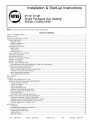
TABLE
SAFETY
CONSIDERATIONS
INTRODUCTION
RECEIVING
OF CONTENTS
.....................................................................................................................................................................................
2
..........................................................................................................................................................................................................
AND
INSTALLATION
3
..........................................................................................................................................................................
3
CHECK EQUIPMENT
............................................................................................................................................................................................
IDENTIFY
UNIT ................................................................................................................................................................................................
INSPECT
SHIPMENT ........................................................................................................................................................................................
3
3
3
INSTALLATION
................................................................................................................................................................................................
PROVIDE
UNIT SUPPORT ...................................................................................................................................................................................
3
3
ROOF
SLAB
CURB ......................................................................................................................................................................................................
MOUNT ...................................................................................................................................................................................................
3
3
GROUND
MOUNT ............................................................................................................................................................................................
FIELD FABRICATE
DUCTWORK
.......................................................................................................................................................................
3
3
PROVIDE
CLEARANCES
......................................................................................................................................................................................
RIG AND PLACE UNIT .........................................................................................................................................................................................
6
8
CONNECT
INSTALL
INSTALL
CONDENSATE
DRAIN ......................................................................................................................................................................
FLUE HOOD ..........................................................................................................................................................................................
GAS PIPING ..........................................................................................................................................................................................
8
8
9
INSTALL
DUCT
CONNECTIONS
......................................................................................................................................................................
12
CONFIGURING
UNITS FOR DOWNFLOW
(VERTICAL)
DISCHARGE
................................................................................................
INSTALL
ELECTRICAL
CONNECTIONS
........................................................................................................................................................
12
14
HIGH-VOLTAGE
CONNECTIONS
...............................................................................................................................................................
SPECIAL
PROCEDURES
FOR 208-V OPERATION
...................................................................................................................................
CONTROL
VOLTAGE
CONNECTIONS
......................................................................................................................................................
14
15
15
HEAT ANTICIPATOR
SE'FflNG
TRANSFORMER
PROTECTION
15
15
PRE-START-UP
START-UP
..................................................................................................................................................................
...................................................................................................................................................................
..........................................................................................................................................................................................................
16
...................................................................................................................................................................................................................
18
CHECK FOR REFRIGERANT
LEAKS ...............................................................................................................................................................
START-UP
HEATING
AND MAKE ADJUSTMENTS
.....................................................................................................................................
18
18
CHECK
CHECK
HEATING
CONTROL
......................................................................................................................................................................
GAS INPUT .......................................................................................................................................................................................
18
22
ADJUST
CHECK
GAS INPUT ......................................................................................................................................................................................
BURNER
FLAME .............................................................................................................................................................................
22
23
AIRFLOW
RISE ......................................................................................................................................................
23
HEATING
SEQUENCE
OF OPERATION
.....................................................................................................................................................
LIMIT SWITCHES
...........................................................................................................................................................................................
23
23
AUXILIARY
LIMFF SWITCH (ROLLOUT)
.................................................................................................................................................
START-UP
COOLING
AND MAKE ADJUSTMENTS
.....................................................................................................................................
24
24
CHECKING
CHECKING
INDOOR
COOLING
AND TEMPERATURE
COOLING
CONTROL
OPERATION
AND ADJUSTING
REFRIGERANT
AIRFLOW
SEQUENCE
AND AIRFLOW
.......................................................................................................................................
CHARGE ......................................................................................................................
ADJUSTMENTS
OF OPERATION
24
24
.............................................................................................................................
25
....................................................................................................................................................
25
MAINTENANCE
........................................................................................................................................................................................................
AIR FILTER .....................................................................................................................................................................................................
EVAPORATOR
BLOWER
AND MOTOR ....................................................................................................................................................
26
28
28
FLUE GAS PASSAGEWAYS
.........................................................................................................................................................................
COMBUSTION-AIR
BLOWER ......................................................................................................................................................................
30
30
LIMIT SWITCH ...............................................................................................................................................................................................
BURNER
IGNITION ........................................................................................................................................................................................
31
31
Form:
IM-PY1P-03
Cancels:
IM-PY1P-02
Printed in U.S.A.
11-02
Catalog No.
53PY-1P15
MAIN
.............................................................................................................................................................................................
31
CONDENSER
CONDENSATE
CONDENSER
BURNERS
COIL, EVAPORATOR
COIL, AND
DRAIN PAN ..........................................................................................................................................................................
FAN ..........................................................................................................................................................................................
33
33
ELECTRICAL
REFRIGERANT
CONTROLS
CIRCUIT
34
35
AND WIRING ..................................................................................................................................................
...............................................................................................................................................................................
GAS INPUT ......................................................................................................................................................................................................
EVAPORATOR
AIRFLOW
.............................................................................................................................................................................
35
35
METERING
35
LIQUID
DEVICE
LINE
TROUBLESHOOTING
START-UP
NOTE
ACUTROL
STRAINER
DEVICE
.............................................................................................................................................
..............................................................................................................................................................................
35
...............................................................................................................................................................................................
35
............................................................................................................................................................................................
35
CHECKLIST
TO INSTALLER
Before
User's Manual and Replacement
or structures
under construction.
the installation,
Guide
READ
THESE
are left with the unit after
INSTRUCTIONS
installation.
CAREFULLY
The furnace
AND COMPLETELY.
is NOT to be used for temporary
Also,
make sure the
heating
of buildings
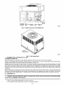
A99338
Fig. 1--Unit
PYIP and PY2P
(Low NOx Model Available)
SAFETY
installation
qualified
and servicing
personnel
Untrained
of air*conditioning
should
personnel
install,
can perform
repair,
equipment
or service
basic maintenance
service personnel.
When working on air-conditioning
other safety precautions
that may apply.
Follow
all safety
all brazing
codes.
Wear safety
glasses
CONSIDERATIONS
can be hazardous
air*conditioning
functions
of cleaning
equipment,
and work gloves.
clue to system
pressure
and electrical
components.
Only
trained
and
equipment.
coils and filters.
observe
precautions
Use quenching
All other
in the literature,
cloth for unbrazing
operations
should
tags, and labels
operations.
Have
be performed
attached
by trained
to the unit, and
fire extinguisher
available
for
operations.
WARNING:
Improper installation, adjustment, alteration, service, maintenance, or use can cause carbon monoxide
poisoning, fire, or an explosion which can result in personal injury or unit damage. Consult a qualified installer, service
agency, or gas supplier for information or assistance. The qualified installer or agency must use only factory-authorized kits
or accessories when modifying this product.
A
WARNING:
Before performing service or maintenance operations on unit, turn off gas supply to unit. Then turn off unit
main power switch and install lockout tag, Electrical shock or explosion could cause serious injury or death.
Recognize
safety information.
for personal injury.
Understand
identifies
or death.
the signal
words
This is the safety-alert
DANGER,
WARNING,
symbolz_x.
CAUTION,
When
you see this symbol
and NOTE.
These
words
in instructions
are used with
or manuals,
be alert to the potential
the safety*alert
symbol.
DANGER
the most serious hazards which will result in serious injury or death. WARNING
signifies a hazard which could result in serious injury
CAUTION
is used to identify unsafe practices which would result in minor personal injury or product and property damage. NOTE is
used to highlight
suggestions
which
will result
in enhanced
installation,
....
reliability,
2==.
or operation.
These instructions cover minimum requirements and conform to existing national standards and safety codes. In some instances, these instructions
exceed certain local codes and ordinances, especially those that may not have kept up with changing residential construction practices. We require
these instructions as a minimum for a safe installation.
INTRODUCTION
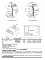
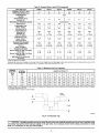
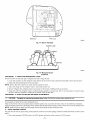
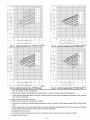
The PYIP and PY2P units (See Fig. I) are fully self-contained, combination Category 1 gas heating/electric cooling units designed for outdoor
installation (See Fig. 2 and 3 for unit dimensions). All unit sizes have return and discharge openings for both horizontal and downflow
configurations, and are factory shipped with all downflow duct openings covered. Units may be installed either on a rooftop, a cement slab, or
directly on the grounst if local codes permit (See Fig. 4 for roof curb dimensions).
Models with an N in the thirteenth position of the model number are dedicated Low NO×units designed for California installations.
These models meet the California maximum oxides of nitrogen (NOx) emissions requirements of 40 nanograms/joule
factory and must be installed in California Air Quality Management Districts where a Low NO× rule exists.
or less as shipped from the
RECEIVING AND INSTALLATION
PROCEDURE
A.
I--CHECK
IDENTIFY
EQUIPMENT
UNIT
The unit model number and serial number are stamped on unit identification plate. Check this information against shipping papers and job data.
Verify unit voltage and amperage requirements listed on unit rating plate agree with power supply provided to unit.
B. INSPECT SHIPMENT
inspect for shipping damage while Emitis still on shipping pallet. If unit appears to be damaged or is torn loose from its anchorage, have it examined
by transportation inspectors before removal. Forward claim papers directly to transportation company. Manufacturer is not responsible for any
damage incurred in transit.
Check all items against shipping list. immediately notify the nearest distributor if any item is missing.
To prevent loss or damage, leave all parts in original packages until installation.
C.
INSTALLATION
1. Remove
unit from
unit. if the wood
2. Position
shipping
carton.
the lifting
bracket
assembly
3. Place each of the 4 metal
4. Thread
lifting
bracket
a. Open lever
lever
5. Tighten
the tension
6. Attach
field-supplied
tension
buckle
lifting
point
9. Lift unit. When
PROCEDURE
A.
in the composite
accessory
roofing,
straps
from damaging
the
does not twist.
pan.
of unit as follows:
of sufficient
To release
strapping,
squeeze
must
strength
to hole in the lifting bracket
or hook
center
be secure
safety
brackets
at the 4 rigging
latch,
in the rigging
brackets.
lift lever,
and pull
webbing
outward.
holds.
(See Fig. 7B).
DO NOT
attach
the safety
straps
to the
of gravity.
over the roof curb, remove
the 2 safety
straps.
Lower
the equipment
onto the roof curb.
SUPPORT
improperly
Curb
roof curb in accordance
and flashing.
IMPORTANT:
Ductwork
The gasketing
applied
should
SLAB
gasketing
be level to within
for additional
information
with instructions
must be attached
shipped
with curb (See Fig. 4 for roof curb dimensions),
of the unit to the roof curb is critical
can also result
insulation,
cant strips,
for a watertight
seal. Install
gasketing
material
supplied
with the roof curb.
in air leaks and poor unit performance.
1/4 in. This is necessary
for unit drain
to function
properly.
Refer to accessory
roof curb installation
instructions
as required.
MOUNT
GROUND
for condensate
PROCEDURE
all ducts
The slab should be flush on the compressor
sides of the unit (See Fig. 6). Do not secure
MOUNT
The unit may be installed
Secure
install
to curb.
Place the unit on a solid, level concrete pad that is a minimum of 4 in. thick with 2 in. above grade.
end of the unit (to allow condensate
drain installation)
and should extend 2 in. on the three remaining
the unit to the slab except when required
by local codes.
C.
the rigging
from damage.
in Fig. 7A.
buckle.
to the clevis
over the unit's
UNIT
Be sure the strap
unit
ROOFCURB
install
B.
directly
bar to prevent
to protect
unit taut.
in tension
or hook
unit is directly
2--PROVIDE
as shown
until it is taut. Lifting
clevis
holds
perimeter
length
type).
buckle
7. Attach the 2 safety straps directly
lifting brackets (See Fig. 7B).
8. Position
into the rigging
buckle
to lock strap
skid on the unit as a spreader
bar of sufficient
the base of the unit.
bottom
(ratchet
tension
through
down
around
around
buckle
through
c. Pull strapping
top shipping
use a spreader
lifting brackets
strapping
of tension
b. Feed strapping
d. Snap
Leave
skid is not available,
either
on a slab or placed
directly
on the ground
if local codes
permit.
Place the unit on level ground
prepared
with gravel
discharge.
3--FIELD
FABRICATE
to roof curb and building
DUCTWORK
structure
on vertical
discharge
units. Do not connect
ductwork
to unit. For horizontal
is provided with flanges on the horizontal
openings.
Installation
of flexible duct connector is recommensted
to prevent
and/or noise to structure. All ductwork should be secured to the flanges, insulate and weatherproof
all external ductwork,
with counter flashing and mastic in accordance
with applicable
codes.
....
3___
applications,
unit
transmission
of vibration
joints, and roof openings
BLOCKOFF
PANELON0180NL/_
\
\
SUPPLT
DUCT
0PENIN6
[15.83]
RETUR_
DUCT
OPENING
I
I
/
EVAP_ C01L _
TOP VIEW
[3_48]
--
249_6
--550.5
149_6
REAR VIEW
REQUIRED CLEAP_,NCE TO COMGUSTIBLE
MATL,
REQUIRED
TOP OF UNIT ...................................................................................
DUCT S DE OF UNIT .........................................................................
SIDE OPPOSITE DUCTS ................................................................
BOTTOM OF UN T .............................................................................
ELECTRIC
HEAT PANEL .................................................................
iNCHES [mm]
1400
3556]
2.00 508
1400
3558]
0.50 127
3600 [9t4 4]
CLEARANCE F0N OPERATION AND SERVICING
EVAR CO_L ACCESS SIDE ............................................................
POWER ENTRY SIDE ....................................................................
iNCHES [mm]
36.00 9140
36001914
0l
(EXCEPT FOR NEe REQUIREMENTS)
UNIT TOP .......................................................................................
S DE OPPOS TE DUCTS ..............................................................
DUCT PANEL .................................................................................
48.00
3600
1200
[1219.2
[9 40
[304 8]
*
NEC. REQUIRED CLEARANCES.
*MINIMUM
DISTANCES:
IF UNIT iS PLACED LESS THAN 1200 [304 8] PROM
WALL SYSTEM, THEN SYSTEM PERFORMANCE
MAYBE COMPROMISE
_NCHES mm]
BETWEEN
UN TS, POWER ENTRY S DE ....................................
4200
10668
UNIT AND UNGROUNDED
SURFACES,
POWER ENTRY SIDE 3600 [91401
UNIT AND BLOCK OR CONCRETE
WALLS AND OTHER
GROUNDED
SURFACES,
POWER ENTRY SIDE .........................
4206 [1066 8]
Note: Wire Grilles are a field installed
option.
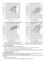
LEGEND
CG- Center of Gravity
COND- Coi_densor
EVAP_ Evaporator
NEC -National
Electrical
Code
REQrD- Required
NOTE:Dimensions are in in [mm]
I193_
[4700]
--1163
[4.58]
t
I
42 7
[h_B]
_72
/J,
,
50
[0.20]
4
[2_85]
122_3
[482B]
_31.0
[32.72]
LEFT
,
L_COMPRES_OR, BLO_ER_ GAS SECTION
& ELECTRICAL ACCESS PANEL
--326_5
FRONT VIEW
SIDE VIEW
RIGHT SIDE VIEW
C00055
CENTER OF GRAVITY
ELECTRICAL
UNIT
PYtPO18040
PY1 P824040/860
PY1 P930040/860
PY1 P936060/890
PY1 P942060/890
PY2P824040/060
PY2P930040/860
PY2P936060/890
CHARACTERISTICS
208/230-1-60
208/230-1-60
208/230-I-60,
208/230-3-60
208/230-1-60, 208/230-3-60, 460-3-60
208/230-1-60, 208/230-3-60, 460-3-60
208/230-1-60
208/230-I-60,
208/230-3-60
208/230-1-60, 208/230-3-60, 460-3-60
UNIT WEIGHT
Ib
249.0
280.0
280.0
320.0
355.0
290.0
313.0
321.0
Fig. 2--PYIP018-042
Ducts
passing
through
if a plenum
return
A minimum
clearance
an unconditioned
is used on a vertical
is not required
space
must be insulated
unit, the return
around
ductwork.
should
Cabinet
UNIT HEIGHT IN. (MM)
"A"
k9
113.2
127.3
127.3
145.1
161.4
131.5
142.0
145.6
35.02
35.02
35.02
37.02
35.02
37.02
39.02
35.02
(889.5)
(889.5)
(889.5)
(940.3)
(889.5)
(940.3)
(991.1)
(889.5)
20.0
22.5
21.5
22.5
21.5
22.0
22.0
22.0
X
(508.0)
(571.5)
(548.1)
(571.5)
(548.1)
(558.8)
(558.8)
(558.8)
IN. {aM)
Y
14.0 (355.6)
13.0 (330.2)
13.75 (349.3)
14.0 (355.6)
13.5 (342.9)
14.5 (368.3)
15.3 (387.4)
15.3 (387.4)
15.0
15.0
15.0
13.0
13.0
16.0
17.6
16.5
and PY2P024_036 Unit Dimensions
and covered
be ducted
return-air
....
4 ....
with a vapor
barrier.
through
the roof deck
static
shall not exceed
to comply
with applicable
-.25 in. wg.
fire codes.
Z
(381.0)
(381.0)
(381.0)
(330.2)
(330.2)
(406.4)
(447.0)
(419.1)
li
tttil
j
lllLL
402T0
•
[15i_3]
SUPPLY
DUCT
1
FURN
JCT
NING
L
OPENING
3512
[13 83]
[3.48]
4066
[16 01]
"
T
COND
Y
EVAP
COIL _
1
3473
[13 67]
TOP VIEW
[ 13.83]
REARVIEW
REQUIRED CLEARANCE TO COMBUSTIBLE MATL.
REQUIRED CLEARANCE FOR OPERATION AND SERVICING
INCHES
14.00
2.00
14.00
0.50
36.00
TOP OF UNIT ...................................................................................
DUCT SIDE OF UNIT .........................................................................
SIDE OPPOSITE DUCTS ................................................................
BOTTOM OF UNIT .............................................................................
FLUE PANEL ....................................................................................
[mm]
[355.6]
[50.8]
[355.6]
[12.7]
[914.4]
EVAP. COIL ACCESS SIDE ............................................................
POWER ENTRY SIDE ....................................................................
(EXCEPT FOR NEC REQUIREMENTS)
UNIT TOP .......................................................................................
SIDE OPPOSITE DUCTS ..............................................................
DUCT PANEL .................................................................................
INCHES [mini
36.00 [914.0]
36.00 {914.0]
48.00 [1219.2]
36.00 [914.0[
12.00 [304.8] *
NED. REQUIRED CLEARANCES.
INCHES
BETWEEN UNITS, POWER ENTRY SIDE .................................... 42.00
UNIT AND UNGROUNDED SURFACES, POWER ENTRY SIDE .36.00
UNIT AND BLOCK OR CONCRETE WALLS AND OTHER
GROUNDED SURFACES, POWER ENTRY SIDE ......................... 42.00
[mm]
[1066.8]
[914.0]
*MINIMUM DISTANCES: IF UNIT IS PLACED LESS THAN 12.00 [304.8] FROM
WALL SYSTEM, THEN SYSTEM PERFORMANCE
MAYBE COMPROMISE.
Note:
[1066.8]
Wire Grilles are a field installed
option.
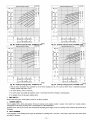
LEGEND
CG- Centerof Gravity
COND- Condensor
EVAP- Evaporator
NEC- NationalElectricalCode
REQ'D- Required
1193.9
[47 00]
1090B
[4294]
NOTE:Dimensionsare in in. [ram]
--115.4
[454]
t
\
T ] 141111 llllll
/ !Jlttt
[I
6_]
_3290
_;2
1123 I
[44 22]
PY1 P048090/115/130
PY1 P060090/115/130
PY2P042060/090
PY2P048090/115/139
PY2P060090/115/139
ELECTRICAL
208-230/1/60,
208/230-1-60,
208/230-1-60,
208/230-1-60,
208/230-1-60,
FLUE HOOD
_OMPRES_OR,
BLOWER, GAS SECTION
& ELECTRICAL ACCESS PANEL
[1295]
4
[285]
122L3
[48.2_]
LEFT SIDEVIEW
UNIT
it tttl
[5.61]
FRONTVIEW
CHARACTERISTICS
208/230-3-60,
2081230-3-60,
208/230-3-60,
208/230-3-60,
208/230-3-60,
460-3-60
460-3-60
460-3-60
460-3-60
460-3-60
Fig. 3--PYIP048-060
UNIT WEIGHT
Ib
415
450
382
421
468
k9
188.6
204.5
173.3
191.0
212.3
RIGHTSIDE VIEW
UNIT HEIGHT
"A"
and PY2P042-060
38.98
38.98
38.98
38.98
42.98
CENTER
IN. (MM)
(990.2)
(990.2)
(990.2)
(990.2)
(1091.1)
X
22 (558.5)
22 (558.5)
23.0 (584.2)
21.5 (546.1)
23.5 (596.9)
Unit Dimensions
C00056
OF GRAVITY
IN. (MM}
Y
16 (406.4)
16 (406.4)
16.3 (412.8)
16.6 (422.1)
16.3 (412.8)
Z
17 (432.0)
17 (432.0)
16.6 (421.6)
18.0 (457.2)
17.6 (447.0)
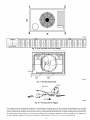
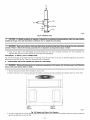
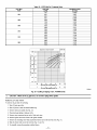
Roof
Curb
for Small
Cabinet
Roof
Note A: When unit mounting screw is used,
retainer bracket must also be used.
Curb
for Large
Cabinet
Note A: When unit mounting screw is used,
retainer bracket must also be used.
,
\
R/A
/
\
\
/
S/A
\\\
insulated
deck
\
"_-_Gssket
Gasket
pan
outer
ductareund_
/
_
around
edge
\
\x
COOO76
UNIT SIZE
PYIP018-042
PYIP048-060
ODS CATALOG
PY2P024-036
PY2P042-060
NUMBER
A
B
C
D
iN. (aM)
IN. (MM)
IN. (MM)
IN. (MM)
CPRFCURB006A00
8 (203)
11(279)
161/2 (419)
28-3/4
CPRFCURB007A00
14 (356)
11(279)
161/2 (419)
28-3/4
CPRFCURB008A00
8 (203)
16 3/16 (411)
17 3/8 (441)
40-1/4
(1022)
CPRFCURB009A00
14 (356)
16 3/16 (411)
17 3/8 (441)
40-1/4
(1022)
(730)
(730)
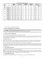
NOTES:
1. Ro_ curb mustbe setup Drunitbeinginstalled.
2.
3.
4.
5.
6.
7.
8.
g.
Seal strip must be applied, as required, to unit being installed.
Dimensions in ( ) are in millimeters.
Roof curb is made of f6-gage steel.
Table lists only the dimensions, per part number, that have changed.
Attach ductwork to curb (flanges of duct rest on curb).
Insulated panels: 1-in. thick fiberglass 1 Ib density.
Dimensions are in inches.
When unit mounting screw is used (see Note At, a retainer bracket must be used as well. This bracket must also be used when required by code for hurricane or seismic
conditions. This bracket is available through Micromefl.
Fig.
PROCEDURE
4---PROVIDE
4--Roof
Curb
Dimensions
CLEARANCES
The required minimum operating and service clearances are shown in Fig. 2 and 3. Adequate combustion, ventilation and condenser air must be
provided in accordance with section 5.3, Air for Combustion and Ventilation, of the National Fuel Gas Code ANSI (American National Standards
institute) Z223.1 or spplicable provisions of local building code. In Canada, follow sections 7.2, 7.3, or 7.4 or CardCGA. (Canadian Gas
Association) B149 Installation Codes or applicable provisions of local building code.
CAUTION: Do not restrict condenser airflow. An air restriction at either the outdoor*air inlet or the fan discharge can
be detrimental to compressor life.
....
6__.
1
2
!
Y
©
Z
3
X
C00070
CORNER #
1
2
3
4
TOTAL WEIGHT
018
47.3
44.8
77.2
79.7
249
024
53.2
50.4
86.8
89.6
280
PYIP
036
59.7
56.5
97.3
106.5
320
030
53.2
50.4
86.8
89.6
280
PY2P
042
67.5
63.9
110.1
113.6
355
Fig. 5--PYIP
048
78.9
74.7
128.7
132.8
415
060
85.5
81.0
139.5
144.0
450
024
55.1
52.2
89.9
92.8
290
030
59.5
56.3
97.0
100.2
313
036
61.0
57.8
99.5
102.7
321
042
72.6
68.8
118.4
122.2
382
048
80.0
75.8
130.5
134.7
421
060
88.9
84.2
145.1
149.8
468
and PY2P Unit Corner Weights
I
EVAP.
COIL
COND.
COIL
C99014
Fig. 6--Slab
Mounting Details
HOOK
FEED
C99067
Fig. 7A--Threading
Bolt for Rigging
The condenser fan pulls air through the condenser coil and discharges it through the top cover. Be sure that the fan discharge does not recirculate
to the condenser coil. Do not locate the unit in either a corner or under an overhead obstruction. The minimum clearance under a partial overhang
(such as a normal house overhang) is 48-in. above the unit top. The maximum horizontal extension of a partial overhang must not exceed 48-in..
Do not place the unit where water, ice, or snow from an overhang or roof will damage or flood the unit. Do not install the unit on carpeting, tile,
or other combustible materials. The unit may be installed on wood flooring or on Class A, B, or C roof covering materials.
....
7 ....
C99015
MAXIMUM WEIGHT
SIZE
A
I
kg
in.
B
I
mm
I
mm
JNIT PYIP
018
271
123.2
20.0
508.0
14.0
355.6
024
302
137.3
22.5
571.5
13.0
330.2
030
302
137.3
21.5
546.1
13.75
349.3
036
342
155.1
22.5
571.5
14.0
355.6
042
377
171.4
21.5
546.1
13.5
342.9
048
437
198.6
22.0
558.5
17.0
432.0
060
472
214.5
22.0
558.5
17.0
432.0
INIT PY2P
024
312
142
22.0
558.5
14.50
368.3
030
335
152
22.0
558.5
15.30
388.6
036
343
156
22.0
558.5
15.30
388.6
042
404
183
23.0
584.2
16.3
414.0
048
443
201
21.5
546.1
16.3
414.0
060
490
222
23.5
596.9
16.3
414.3
PROCEDURE
5--RIG
CAUTION:
Use spreader
AND
When
PLACE
installing
UNIT
Fig. 7B--Suggested
the unit
bars or crate top when rigging
on a rooftop,
be sure
Rigging
the roof will support
the unit. The units must be rigged
the additional
for lifting (See Fig. 6). Refer to Table
weight.
1 and 2 for operating
weight.
Use extreme caution
to prevent
damage
when moving the unit. Unit must remain in an upright position
during all rigging
and moving
operations.The
unit must be level within I/4" for proper condensate
drainage; therefore, the ground-level
pad or accessory
roof curb must be level
before setting the unit in place. When a field-fabricated
support is used, be sure that the support is level and properly supports the unit. Lifting
point should be directly over the center of gravity
PROCEDURE
6--CONNECT
CONDENSATE
NOTE:
When
installing
Models PYIP and PY2P
and 3 for location).
Condensate
water
condensate
dispose
for the unit.
DRAIN
drain connection
be sure to comply
with local codes
of condensate
water through
a 3/4 in. NPT fitting which
directly
the roof
installations
can be drained
onto
in rooftop
and restrictions,
exits through the compressor
(where
permitted)
or onto
access
a gravel
panel
apron
(See Fig. 2
in ground-level
installations.
Install a field-supplied
condensate
trap at end of condensate
connection
to ensure proper drainage. Make sure that the outlet of the
trap is at least 1 in. lower than the drain pan condensate
connection
to prevent the pan from overflowing
(See Fig. 8). Prime the trap with water.
When
using
a gravel
apron,
make sure
it slopes
away
from the unit,
if the installation
requires draining the condensate
water away from the unit, install a 2-in. trap at the condensate
connection
to ensure proper
drainage (See Fig. 8). Make sure that the outlet of the trap is at least I in. lower than the drainpan
condensate
connection.
This prevents the pan
fi'om overflowing.
Prime the trap with water, Connect a drain tube - using a minimum
of 3/4-in. PVC or 3/4-in. copper pipe (all field-supplied)
- at the outlet end
of the 2-in. trap. Do not undersize
the tube. Pitch the drain tube downward
at a slope of at least 1-in. for every 10 fl of horizontal
run. Be sure
to check the drain tube for leaks.
PROCEDURE
The flue hood
assembly
NOTE:
7--INSTALL
assembly
FLUE
is shipped
HOOD
screwed
to the coil panel
in the indoor
blower
compartment.
Remove
the service
access
panel
to locate
the
(See Fig. 31).
Dedicated
low NO× models
These models
factory.
meet the California
NOTE:
NO× requirements
Low
MUST
maximum
apply
be installed
oxides
in California
of nitrogen
only to natural
Air Quality
(NO×) emissions
Management
requirements
Districts
where
a Low
of 40 nanograms/joule
NO× rule
exists.
or less as shipped
from the
gas installations.
A
CAUTION: The venting system is designed to ensure proper venting. The flue hood assembly must be installed as
indicated in this section of the unit installation instructions.
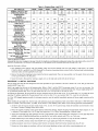
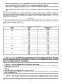
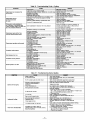
Table l--Physical
NOMINAL
CAPACITY
Data--Unit
PYIP
018040
024040
024060
030040
030060
036060
036090
042060
(ton)
1½
2
2
2½
2½
3
3
3½
(lb.)
249
280
280
280
280
320
320
355
042090
3½
355
4.4
4.4
5.7
5.7
UNIT SIZE PYIP
OPERATING WEIGHT
COMPRESSORS
Quantity
Reciprocating
1
REFRIGERANT (R-22)
Quantity (lb.)
REFRIGERANT METERING
Orifice ID (in.)
2.6
3.5
3.5
3.65
3.65
.034
.034
.034
.034
.034
.032
.032
.034
.034
1-.17
6.1
1...17
9.1
1.-17
9.1
1.-17
9.1
1_.17
9.1
1..,17
10.9
1...17
10.9
1.-17
9.1
1.-17
9.1
2000
22
2400
22
2400
22
2400
22
2400
22
3000
22
1/8 (825)
1/8 (825)
1/8 (825)
1/8 (825)
¼ (1100)
3000
22
¼ (1100)
3000
22
1/8 (825)
3000
22
¼ (1100)
¼ (1100)
2-.15
3.1
2.-15
3.1
2.-15
3.1
2,-15
3.1
2.,.15
3.1
3..,15
3.1
3...15
3.1
4...15
3.1
4.-15
3.1
600
10x10
1/4 (875)
800
10x10
114 (1075)
800
10 x 10
114 (1075)
1200
11x10
1/2 (1075)
1200
11 x 10
112 (1075)
1400
11 x 10
3_ (1075)
1400
11 x 10
3_ (1075)
2.-45
2.-50
2...45
2...50
2.-38
2.-46
2,-45
2,-50
2.,.38
2._46
2..,38
2...46
3...38
3-.46
2.-38
2.-46
3,..38
3.-46
20 x 20
20 x 20
20 X 20
20 x 20
20 X 20
20 X 24
20X24
20x24
20 x 24
Acutrol
DEVICE
CONDENSER COIL
Rows...Fins/in.
Face Area (sq ft)
CONDENSER FAN
Nominal Cfm
Diameter (in.)
Motor Hp (Rpm)
EVAPORATOR COIL
Rows...Fins/in.
Face Area (sq ft)
EVAPORATOR BLOWER
Nominal Airflow (Cfm)
Size (in.)
Motor HP (Rpm)
FURNACE SECTION*
Burner Orifice No. (Qty_.Drill Size)
Natural Gas
Burner Orifice No. (Qty_.Drill Size)
Propane Gas
RETURN-AIR FILTERS (in.)t
Throwaway
Device
TM
1000
1000
10x10
10x10
1/4 (1o75) 1/4 (1075)
* Based on aRitude of 0 to 2000 ft.
t Required filter sizes shown are based on the larger of the ARI (Air Conditioning and Refrigeration Institute) rated cooling airflow or the heating
if/minute for throwaway type or 450 ft/minute for high-capacity type. Air filter pressure drop for non-standard filters must not exceed 0.08 in. wg.
install
the flue hood
ai_ow
velocity of 300
as follows:
i. This installation must conform with local building codes and with the National Fuel Gas Code (NFGC), ANSI Z223.1 (in Canada,
CAN/CGA B i49. I, and B 149.2) or NFPA (National Fire Protection Association) latest revision. Refer to Provincial and local plumbing or
wastewater codes and other applicable local codes.
2. Remove flue hood #am shipping location (inside the blower compartment).
in vent cap with holes in the flue panel.
3. Secure
flue hood
PROCEDURE
to flue panel by inserting
8--INSTALL
a single
screw
Place vent cap assembly over flue panel. Orient screw holes
on the right side and the left side of the hood.
GAS PIPING
The gas supply pipe enters the unit through the access hole provided. The gas connection to the unit is made to the i/2-in. FPT gas inlet on the
manual shutoff or gas valve.
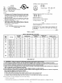
install a gas supply line that runs to the heating section, Refer to Table 3 and the NFGC for gas pipe sizing. Do not use cast-iron pipe, It is
recommended that a black iron pipe is used. Check the local utility for recommendations concerning existing lines. Size gas supply piping for 0.5
in. wg maximum pressure drop. Never use pipe smaller than the 1/2-in. FPT gas inlet on the unit gas valve.
For natural gas applications, the gas pressure at unit gas connection must not be less than 4.0 in. wg or greater than 13 in. wg while the unit is
operating. For propane applications, the gas pressure must not be less than 7.0 in. wg or greater than 13 in. wg at the unit connection.
An i/8-in. NPT plugged tapping, accessible for test gage connection, must be installed immediately
gas valve.
upstream of the gas supply connection to the
When installing the gas supply line, observe local codes pertaining to gas pipe installations. Refer to the NFGC ANSI Z223.1-1988 NFPA latest
edition (in Canada, CAN/CGA B149. I, (2)-M86). in the absence of local building codes, adhere to the following pertinent recommendations:
i. Avoid low spots in long runs of pipe. Grade all pipe I/4 in. in every
Use risers to connect to heating section and to meter.
2. Protect
all segments
a minimum
of piping
of one hanger
system
every
against
physical
and thermal
6 ft. For pipe sizes larger
than
15 ft to prevent
damage_
Support
I/2 in., follow
traps.
Grade all horizontal
all piping
with appropriate
recommendations
of national
runs downward
to risers.
straps,
etc. Use
hangers,
codes.
3. Apply joint compound (pipe dope) sparingly and only to male threads of joint when making pipe connections. Use only pipe dope that is
resistant to action of liquefied petroleum gases as specified by local and/or national codes. Never use Teflon tupe.
4. Install sediment trap in riser leading to heating section (See Fig. 9). This drip leg functions as a trap for dirt and condensate.
5. Install
an accessible,
6. Install
ground-joint
7. Pressure-test
external,
union
manual
main
close to heating
all gas piping in accordance
shutoff
section
valve
in gas supply
between
unit manual
pipe within
shutoff
6 ft of heating
and external
manual
section.
main shut-off
valve.
with local and national plumbing and gas codes before connecting piping to unit.
....
9 ....
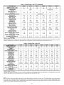
Table 1--Physical
UNIT SIZE PYIP
NOMINAL
CAPACITY
Data--Unit
PYIP (Continued)
048090
048115
048130
(ton)
4
4
4
5
5
5
(lb.)
415
415
415
450
450
450
OPERATING WEIGHT
COMPRESSORS
Quantity
060115
Scroll
1
REFRIGERANT (R-22)
Quantity (lb.)
REFRIGERANT METERING
Orifice ID (in.)
060090
060139
Reciprocating
1
6.0
6.0
6.0
8.0
8.0
8.0
.032
.032
.032
.030
.030
.030
1._17
12.3
1...17
12.3
1...17
12.3
2._17
12.3
2...17
12.3
2...17
12.3
3600
22
3600
22
3606
22
3600
22
3600
22
V, (1100)
3600
22
¼ (1100)
I/, (1100)
¼ (1100)
3._15
4.7
3._15
4.7
3.-15
4.7
4-.15
4.7
4_,15
4.7
1600
11 X 10
3/4 (1075)
1600
11X 10
3/4 (1075)
1600
11X10
3/4 (1075)
2000
11X10
1.0 (1075)
2000
11 X 10
1.0 (1075)
2000
11 X 10
1.0 (1075)
3...38
3._46
3...33
3-.42
3...31
3.-41
3.-38
3-.46
3_.33
3...42
3...31
3...41
24 X 30
24 X 30
24 X 30
24 X 30
Acut rol Device
DEVICE
CONDENSER COIL
Rows.-Fins/in.
Face Area (sq ft)
CONDENSER FAN
Nominal Cfm
Diameter (in.)
Motor Hp (Rpm)
EVAPORATOR COIL
Rows._Fins/in.
Face Area (sq ft)
EVAPORATOR BLOWER
Nominal Airflow (Cfm)
Size (in=)
Motor Hp (Rpm)
FURNACE SECTION*
Burner Orifice No. (Qty._Drill Size)
Natural Gas
Burner Orifice No. (Qty._Drill Size)
Propane Gas
RETURN-AIR FILTERS (in.)1"
Throwaway
¼ (1100)
V, (1100)
4...15
4.7
24X30
24 X 30
* Based on altitude of 0 to 2000 ft.
Required filter sizes shown are based on the larger of the ARI (Air Conditioning and Refrigeration Instffute) rated cooling airflow or the heating
ft/minute for throwaway type or 450 ftlminute for high-capacity type. Air filter pressure drop for non-standard filters must not exceed 0.08 in. wg.
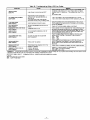
Table 2iphysical
UNIT SIZE PY2P
NOMINAL CAPACITY (ton)
OPERATING WEIGHT (lb.)
COMPRESSORS
Quantity
REFRIGERANT
(R-221
Quantity (lb.)
REFRIGERANT
METERING DEVICE
Orifice ID fin.)
CONDENSER COIL
Rows...Fins/in.
Face Area (sq ft)
CONDENSER FAN
Nominal Cfm
Diameter (in.)
Motor Hp {Rpm)
EVAPORATOR COIL
Rows...Fins/in.
Face Area (sq ft)
EVAPORATOR
BLOWER
Nominal Airflow (Cfm)
Size (in.)
Motor Hp {Rpm)
FURNACE SECTION*
Burner Orifice NO. (Qty...Drgl Size)
Natural Gas
Burner Orifice NO. (Qty...Drgl Size)
Propane Gas
RETURN*AIR FILTERS (in.)_
Throwaway
624040
2
290
024060
2
290
DataiUnit
630046
2½
313
airflow velocity of 300
PY2P
030060
2½
313
036060
3
321
636096
3
321
042060
3½
382
042090
3½
382
Scroll
1
3.7
3.7
4.4
4.4
5.2
5.2
6.4
6.4
.034
.034
.030
.030
.032
.032
.034
.034
1...17
10.8
1...17
10.8
1...17
12.7
1...17
12.7
2._17
g.f
2...17
9.1
2...17
12.3
2...17
12.3
2350
22
1/8 (825)
2350
22
i/8 (825)
2350
22
1/8 (825)
2350
22
118 (825)
2350
22
1_ (825)
2350
22
1/8 (825)
3300
22
im (825)
3300
22
1/8 (825)
3...15
3.1
3...15
3.1
3...15
3.1
3...15
3.1
3...15
3.7
3...15
3.7
3...15
4.7
3...15
4.7
800
10X10
iN (1075)
800
10X10
1/4(1075)
1000
10Xf0
114 (1075)
1000
i0X10
1_ (1075)
1200
11X10
1/2(1075)
1200
11X10
i/2 (1075)
1400
11X10
3/4 (1075)
1400
11Xf0
314 (1075)
2...44
2...50
2...38
2...46
2...44
2...50
2...38
2...46
2._38
2...46
3...36
3...46
2...38
2...46
3...38
3...46
20X20
20X20
20X20
20X20
20X24
20X24
24X30
24X30
* Based on altitude of 0 1o 2000 ft.
Required filter sizes shown are based on the larger of the ARI (Air Conditioning and Refrigeration institute)
ft/minute for high-capacity type. Air filter pressure drop for non-standard filters must not exceed 0.08 in. wg.
rated cooling airflow or the heating
airflow velocity of 300
NOTE: Pressure test the gas supply system after the gas supply piping is connected to the gas valve. The supply piping must be disconnected
from the gas valve during the testing of the piping systems when test pressure is in excess of 0,5 psig. Pressure test the gas supply piping system
at pressures equal to or less than 0.5 psig. The unit heating section must be isolated from the gas piping system by closing the external main manual
shutoff valve and slightly opening the ground-joint union.
.... I0 ....
Table
UNIT SIZE PY2P
NOMINAL
CAPACITY
2iphysical
DataiUnit
PY2P
(Continued)
048090
048115
048130
060090
060115
(ton)
4
4
4
5
5
5
(lb.)
421
421
421
468
468
468
8.1
8.1
8.1
OPERATING WEIGHT
COMPRESSORS
Quantity
060130
Scroll
1
REFRIGERANT (R-22)
Quantity (lb.)
8.3
8,3
8,3
.034
,034
.034
,032
.032
.032
CONDENSER COIL
Rows...Fins/in.
Face Area (sq ft)
2_.17
2_,17
2._17
2...17
2,,.17
2._17
12.3
12.3
12.3
16.4
16,4
16.4
CONDENSER FAN
Nominal Cfm
Diameter (in.)
Motor Hp (Rpm)
3300
22
3300
22
3300
22
3300
22
3300
22
3300
22
¼ (1100)
1/, (1100)
¼ (1100)
¼ (1100)
1/, (1100)
¼ (1100)
EVAPORATOR COIL
Rows...Fins/in.
Face Area (sq ft)
4,,.15
4.7
4..,15
4.7
4._15
4.7
4...15
4.7
4.,.15
4.7
4_.15
4.7
EVAPORATOR B LOWER
Nominal Airflow (Cfm)
Size (in.)
Motor Hp (Rpm)
1600
11 X 10
1600
11 X 10
1600
11 X 10
1750
11 X 10
1750
11 X 10
1750
11 X 10
3/4 (1075)
3/4 (1075)
3/4 (1075)
1.0 (1075)
1.0 (1075)
1.0 (1075)
3-.38
3_.46
3.,,33
3._42
3._31
3._41
3_,38
3_.46
3,-33
3...42
3_.31
3_.41
24 X 30
24 X 30
24 X 30
24 X 30
24 X 30
24 X 30
REFRIGERANT
METERING
Orifice
FURNACE
DEVICE
Acutrol Device
ID (in.)
SECTION*
Burner Orifice No.
Natural
Burner Orifice No.
Propane
(Qty._Drill
Gas
(Qty._Drill
Gas
Size)
Size)
RETURN-AIR FILTERS (in.)1"
Throwaway
* Based on a_titudeof 0 to 2000 ft.
t Required filter sizes shown are based on the larger of the ARI (Air Conditioning and Refrigeration Institute) rated cooling airflow or the heating airflow velocity of 300
if/minute for high-capacity type. Air filter pressure drop for non-standard filters must not exceed 0.06 in. wg.
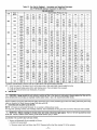
Table
3--Maximum
Gas
Flow
Capacity*
NOMINAL
IRON PIPE,
SIZE
(IN.)
INTERNAL
DIAMETER
LENGTH OF PIPE, FT t
(IN.)
10
20
30
40
50
60
70
80
90
100
125
150
175
200
'/2
.622
175
120
97
82
73
66
61
57
53
50
44
40
--
--
_/,
.824
360
250
200
170
151
138
125
118
110
103
93
84
77
72
1
1,049
680
465
375
320
285
260
240
220
205
195
175
160
145
135
1'/,
1,380
1400
950
770
600
580
530
490
460
430
400
360
325
300
280
1'/2
1,610
2100
1460
1180
990
900
810
750
690
650
620
550
500
460
430
* Capacity of pipe in cuft of gas per br for gas pressure of 0.5 psig or less. Pressure drop of 0.5-in. wg (based on a 0.60 specific gravity gas). Refer to Table C-4, National
Fire Protection Association NFPA 54.
t This length includes an ordinary
number of fittings.
TRAP
OUTLET
1" rain.
2" rain,
COOOOg
Fig. 8iCondensate
Trap
CAUTION:
Unstable operation may occur when the gas valve and manifold assembly are forced out of position while
connecting improperly*routed rigid gas piping to the gas valve. Use a backup wrench when making connection to avoid
strain on, or distortion of, the gas control piping.
.....]i .........
IN
TEE
I
3-MIN
I
C99020
Fig. 9--Sediment
Trap
CAUTION: If a flexible conductor is required or allowed by the authority having jurisdiction,
installed at the gas valve and shall extend a minimum of 2 in. outside the unit casing.
black iron pipe shall be
WARNING:
Never use a match or other open flame when checking for gas leaks. Never purge gas line into combustion
chamber. Failure to follow this warning could result in an explosion causing serious injury or death.
8. Check for gas leaks at the field-installed and factoryqnstalled
gas lines after all piping connections
soap-and-water solution (or method specified by local codes and/or regulations).
PROCEDURE
9--INSTALL
have been completed.
DUCT CONNECTIONS
The unit has duct flanges on the supply- and return-air openings on the side and bottom of the unit. For downshot applications,
connects to the roof curb (See Fig. 2 and 3 for connections sizes and locations).
A.
CONFIGURING
Use
UNITS FOR DOWNFLOW
(VERTICAL)
the ductwork
DISCHARGE
WARNING:
Before performing service or maintenance
shock could cause serious injury or death.
operations on the system, turn off main power to unit. Electrical
I. Open all electrical disconnects before starting any service work.
2. Remove return duct cover located on duct panel by breaking connecting tabs with screwdriver
and a hammer (See Fig. 10A & 10B).
o
/
•
o
;UPPLY
DUCT
OPENING
RETURN
DUCT
OPENING
C99011
3. To remove
supply
duct cover, break
Fig. 10A Supply and Return Duct Opening
fi'ont and right side connecting
tabs with a screwdriver
and left side tabs (See Fig. 10A & 10B).
.... 12....
and a hammer.
Push louver
down to break rear
DUCT COVERS REMOVED
C99012
Fig. lOB---Vertical
4. If unit ductwork
z_
CAUTION:
is to be attached
Collect
to vertical
ALL screws
opening
that were
flanges
removed.
Duct Cover Removed
on the unit composite
Do not leave
screws
base 0ackstand
on rooftop
applications
as permanent
only),
do so at this time.
damage
to the roof may
occur,
5. It is recommensted that the unit base insulation around the perimeter of the vertical return-air opening be secured to the unit base with
aluminum tape. Applicable local codes may require aluminum tape to prevent exposed fiberglass.
6. Cover both horizontal duct openings with the duct covers fi'om the accessory duct cover kit. Ensure opening is air- and watertight.
7. After completing unit conversion, perform all safety checks and power up unit.
NOTE: The design and installation of the duct system must be in accordance with the standards of the NFPA for installation of nonresidenceqype
air conditioning and ventilating systems, NFPA 90A or residence*type, NFPA 90B; and/or local codes and ordinances.
Adhere to the following criteria when selecting, sizing, and installing the duct system:
1. Units are shipped for horizontal duct installation (by removing duct covers).
2. Select and size ductwork, supply*air registers, and return*air grilles according
Constitioning Engineers (ASHRAE) recommendations.
to American
Society of Heating, Refrigeration
3. Use flexible transition between rigid ductwork and unit to prevent transmission
duct flanges. Use suitable gaskets to ensure weathertight and airtight seal.
of vibration. The transition may be screwed or bolted to
4. All units must have field*supplied filters or accessory filter rack installed in the return*air side of the unit. Recommended
are shown in Tables 1 and 2.
and Air
sizes for filters
5. Size all ductwork for maximum required airflow (either heating or cooling) for unit being installed. Avoid abrupt duct size increases or
decreases or performance may be affected.
6. Adequately insulate and weatherproof all ductwork located outdoors, insulate ducts passing through unconditioned space, and use vapor
barrier in accordance with latest issue of Sheet Metal and Air Conditioning Conlractors National Association (SMACNA) and Air
Conditioning Contractors of America (ACCA) minimum installation standards for heating and air conditioning systems. Secure all ducts
to building structure.
7. Flash, weatherproof, and vibration-isolate
all openings in building structure in accordance with local codes and good building practices.
.... 13....
PROCEDURE
10--INSTALL
ELECTRICAL
CONNECTIONS
WARNING:
The unit cabinet must have an uninterrupted, unbroken electrical ground to minimize the possibility of
serious injury if an electrical fault should occur. This ground may consist of an electrical wire connected to the unit ground
lug in the control compartment, or conduit approved for electrical ground when installed in accordance with NEC (National
Electrical Code) ANSI/NFPA (latest edition) and local electrical codes. In Canada, follow Canadian Electrical Code CSA
(Canadian Standards Association) C22.1 and local electrical codes. Failure to adhere to this warning could result in serious
injury or death.
A
CAUTION: Failure to follow these precautions could result in damage to the unit being installed:
1. Make all electrical connections in accordance with NEC ANSI/NFPA (latest edition) and local electrical codes governing
such wiring, in Canada, all electrical connections must be in accordance with CSA standard C22.1 Canadian Electrical
Code Part 1 and applicable local codes. Refer to unit wiring diagram.
2. Use only copper conductor for connections between field-supplied electrical disconnect switch and unit. DO NOT USE ALUMINUM
WIRE.
3. Be sure that high-voltage power to unit is within operating voltage range indicated on unit rating plate.
4. Do not damage internal components when drilling through any panel to mount electrical hardware, conduit, etc. On 3-phase units,
ensure phases are balanced within 2 percent. Consult local power company for correction of improper voltage and/or phase
imbalance.
A.
HIGH-VOLTAGE
CONNECTIONS
The unit must have a separate electrical service with a field-supplied, waterproof, disconnect switch mounted at, or within sight from, the unit.
Refer to the unit rating plate for maximum fuse/circuit breaker size and minimum circuit amps (ampacity) for wire sizing (See Tables 4 and 5 for
electrical data).
The field*supplied disconnect switch box may be mounted on the unit over the high-voltage inlet hole when the standard power and low-voltage
entry points are used (See Fig. 2 and 3 for acceptable locution).
See unit wiring label and Fig. 11 for reference when making high voltage connections. Proceed as follows to complete the high-voltage connections
to the unit.
m
HIGHVOLTAGE
r-
-
-
-
POWER
LEADS
(SEE
UNIT
WIRING 4¢cLABEL)
_-
--_-FIELD-SUPPLIED
FUSED DISCONNECT
GND
CONTROL
BOX
OLOW-VOLTAGE
POWER LEADS(SEE UNIT
_
O- _G_RN_(G_)
_
(TTHy_
IRcMAOL_
TAT
O-
WIRING LABEL)
_O-
SPLICE BOX
C99018
Fig. 11--High-
and Control-Voltage
Connections
Single phase units:
I. Run the high*voltage (LI, L2) and ground leads into the control box.
2. Connect ground lead to chassis ground connection.
3. Connect LI to pressure lug connection I 1 of the compressor contactor.
4. Connect L2 to pressure lug connection 23 of the compressor contactor.
Three-phase
units:
I. Run the high-voltage (LI, L2, L3) and ground leads into the control box.
2. Connect ground lead to chassis ground connection.
3. Locate the black and yellow wires connected to the lines side of the contactor.
4. Connect field LI to black wire on connection
11 of the compressor
5. Connect field wire L2 to yellow wire on connection
contactor.
13 of the compressor
.... 14....
contactor.
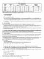
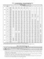
Table4--Electrical
UNIT
SIZE
PYIP
VOLTAGE
RANGE
V-PH-HZ
Data--Unit
COMPRESSOR
Min
Max
PYIP
OUTDOOR FAN
MOTOR
INDOOR FAN
MOTOR
FLA
MCA
Max Fuse or
C_ Bkr
RLA
LRA
FLA
POWER SUPPLY
018
208/230-1-60
187
253
9.0
45.0
0.8
1.8
13.9
20
024
208/230-1-60
187
253
12.8
61.0
0.8
2,0
18.8
30
208/230-1-60
187
253
14.4
73.0
0.8
2,0
20.8
30
208/230-3-60
187
253
12.6
68.0
2,0
13.2
20
208/230-1-60
187
253
13.0
81.0
0.8
1.6
3.6
24.0
35
208/230-3-60
187
253
9.0
78.0
1.6
3.6
16.5
25
460-3-60
414
506
4.5
40.0
0.9
1.9
8.4
15
208/230-1-60
187
253
18.6
105.0
1.6
3.8
27.5
45
208/230-3-60
187
253
10.7
85.0
1.6
3.8
18.8
25
460-3-60
414
506
5.3
42.0
0.9
2,0
9.5
15
208/230-1-60
197
253
25.3
131.0
1.6
3.8
37.0
60
208/230-3-60
187
253
13.5
108.0
1.6
3.8
22.3
35
460-3-60
414
506
6.7
47.5
0.9
2,0
11.3
15
208/230-1-60
187
253
28.9
147.0
1.6
6.2
43.9
60
208/230-3-60
187
253
18.6
125.0
1.6
6.2
31.1
45
460-3-60
414
506
8.5
66.5
0.9
3.2
14.7
20
030
036
042
848
060
6. Connect field wire L3 to Blue wire from compressor.
B.
SPECIAL PROCEDURES
FOR 208-V OPERATION
z_x WARNING:
Before making any wiring changes, make sure the gas supply is switched off first. Then switch off the power
supply to the unit and install lockout tag, Electrical shock can cause serious injury or death,
C.
CONTROL
VOLTAGE
CONNECTIONS
Do not use any type of power-stealing
Use
no, 18 American
thermostat
Wire
insulated
STANDARD
(35 C minimum)
knockout
installer's
packet
hole located
(included
Run the low-voltage
five
18-gage
leads through
with operation
between
leads
E.
from the thermostat,
wires leaving
hole in bottom
insulated
may result.
(35 C minimum)
wires to make the control
more than 100 fi from the unit (as measured
voltage
along the control
voltage
connections
wires),
between
the
use no. 16 AWG
of control
to the control
grommet
through
box. These
the leads are long enough
access
in the knockout
panel
opening.
(See Fig. 2 and 3). Remove
Provide
a drip loop before
the inlet hole, and into unit low-voltage
low-voltage
connection
to be muted
into the low-voltage
box and make low-voltage
splice
leads can be identified
connections
the rubber
running
grommet
wire through
from the
panel.
box.
by the colors red, green, yellow,
splice box (located
below right side of control
(See Fig. 11). Secure
all cut wires,
heating
Set the heat anticipator,
brown,
box).
and
Route
so that they do not interfere
themmstat
SETTING
heat anticipator
the W and R terminals
may be changed
TRANSFORMER
The trans[brmer
control
adjacent
of unit.
NOTE:
For thermostat
will result in improper
setting
problems
wires.
in the flue panel
HEAT ANTICIPATOR
The room
color-coded,
is located
with unit) and install
(See Fig. 11). Ensure
D.
Unit control
CONNECTION
Remove
white
(AWG)
and the unit, if the thermostat
color-coded,
Locate
Gage
thermostat.
selection
operation,
slightly
must be properly
to determine
adjusted
the exact required
to ensure
proper
performance.
using an ammeter
setting.
purposes, use 0.18 amp for the approximate
required setting. Failure to make a proper heat anticipator
adjustment
discomfort
to the occupants of the conditioned
space, and inefficient
energy utilization;
however, the required
to provide
a greater
degree
of comfort
for a particular
installation.
PROTECTION
is of the energy-limiting
type. It is set to withstand
a 30-sec.
.... 15....
overload
or shorted
secondary
condition.
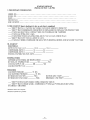
EXAMPLE: Supply voltage is 460-3-60.
FLA
-- Full Load Amps
l_
LIP_I_US
LRA
-- LockedLEGEND
RotorAmps
MCA
-- Minimum Circuit Amps
MOCP -- Maximum Overcurrent Protection
RLA
-- Rated Load Amps
CKT BKR -- Circuit Breaker
A
(_
= 137"1
3
= 457
NOTES:
1. In compliance with NEC (National Electrical Code) requirements
for multimotor and combination load equipment (refer to NEC
Articles 430 and 440), the overcurrent protective device for the
unit shall be Power Supply fuse. Canadian units may be
fuse or circuit breaker.
2. Minimum wire size is based on 60 C copper wire. If other than
60 C wire is used, or if length exceeds wire length in table,
determine size from NEC.
3. Unbalanced
3-Phase Supply Voltage
Never operate a motor where a phase imbalance in supply voltage is greater than 2%. Use the following formula to determine
the percentage of voltage imbalance.
Determine maximum deviation from average voltage.
(AB) 457 452=5v
(BC) 464 457=7v
(AC) 457 455=2v
Maximum deviation is 7 v.
Determine percent of voltage imbalance.
7
% Voltage Imbalance = 100 x -457
= 1.53%
This amount of phase imbalance
maximum allowable 2%.
% Voltage imbalance
= 100 x
AC = 455 v
AB=452V
Average Voltage = 452 + 464 + 455
3
BC = 464 v
B C
max voltage deviation from average voltage
average voltage
is satisfactory
as it is below the
iMPORTANT:
If the supply voltage phase imbalance
is
more than 2%, contact your local electric utility company
immediately.
C99024
Table 4iLegend
Table 5iElectrical
UNIT
SIZE
PY2P
024
030
036
042
048
060
VOLTAGE
RANGE
DataiUnit
COMPRESSOR
V-PH-HZ
PY2P
OUTDOOR FAN
MOTOR
INDOOR FAN
MOTOR
POWER SUPPLY
Min
Max
RLA
LIRA
FLA
FLA
MCA
Max Fuse or
Ckt Bkr
208/23(_1-60
187
253
10.9
54.0
0.9
2.0
15.7
25
208/230-1-60
187
253
13.5
73.0
0.8
2.1
19.8
30
208/230-3-60
187
253
9.0
63.0
0.8
2.1
14.2
20
208/230-1-60
187
253
16.7
97.0
0.8
3.6
25.3
40
208/230-3-60
187
253
11.2
75.0
0.8
3.6
18.4
25
460-3-60
414
506
5.4
37.5
1.9
9.6
15
208/230-1-60
187
253
17.9
104.0
0.9
1.6
4.1
28.1
45
208/23(_3-60
187
253
12.4
88.0
1.6
4.1
21.2
30
460-3-60
414
506
6.1
44.0
0.9
2.0
10.5
208/230-1-60
187
253
23.4
126.0
1.5
4.1
34.9
45
208/230-3-60
187
253
13.0
93.0
1.5
4.1
21.9
30
460-3-60
414
506
6.4
46.5
0.9
1.9
10.8
15
208/230-1-60
187
253
28.8
169.0
1.6
6.2
43.8
60
208/230-3-60
187
253
17.3
123.0
1.6
6.2
29.4
45
460-3-60
414
506
9.0
62.0
0.9
3.2
15.4
20
15
PRE-START*UP
WARNING:
Failure to observe the following warnings could result in serious injury:
1. Follow recognized safety practices and wear protective goggles when checking or servicing refrigerant system.
2. Do not operate compressor or provide any electric power to unit unless compressor terminal cover is in place and secured.
3. Do not remove compressor terminal cover until all electrical sources are disconnected.
4. Relieve and recover all refrigerant from system before touching or disturbing anything inside terminal box if refrigerant
leak is suspected around compressor terminals.
5. Never attempt to repair soldered connection while refrigerant system is under pressure.
6. Do not use torch to remove any component. System contains oil and refrigerant under pressure. To remove a component,
wear protective goggles and proceed as follows:
a. Shut off gas supply and then electrical power to unit,
b. Relieve and recover all refrigerant from system using both high- and low-pressure ports,
c, Cut component connecting tubing with tubing cutter and remove component from unit.
d. Carefully unsweat remaining tubing stubs when necessary, Oil can ignite when exposed to torch flame,
Proceed as follows to inspect and prepare the unit for initial startup:
I. Remove
access
2. Read and follow
panel.
instructions
on all WARNING,
CAUTION,
and INFORMATION
.... 16....
labels attached
to, or shipped
with, unit.
EXAMPLE: Supply voltage is 460-3_60,
A
FLA
-- Full Load Amps
LRA
-- Locked Rotor Amps
b
MCA -- Minimum Circuit Amps
MOCP -- Maximum Overcurrent Protection
RLA
-- Rated Load Amps
CKT BKR -- Circuit Breaker
LEGEND
"@
C
(_
% Voltage imbalance
AB = 452 v
AC = 455 v
118
NOTES:
1. In compliance with NEC (National Electrical Code) requirements
for multimotor and combination load equipment (refer to NEC
Articles 430 and 440), the overcurrent protective device for the
unit shall be Power Supply fuse. Canadian units may be
fuse or circuit breaker.
2. Minimum wire size is based on 60 C copper wire. If other than
60 C wire is used, or if length exceeds wire length in table,
determine size from NEC.
3. Unbalanced
3-Phase Supply Voltage
Never operate a motor where a phase imbalance in supply voltage is greater than 2%. Use the following formula to determine
the percentage of voltage imbalance.
= 100 x
a
Average Voltage = 452 + 464 + 455
3
BC = 464 v
= 1371
3
= 457
Determine maximum deviation from average voltage.
(AB) 457 452=5v
(B0) 464 457=7v
(AC) 457 455=2v
Maximum deviation is 7 v,
Determine percent of voltage imbalance.
% Voltage Imbalance = fog x
!
457
= 1.53%
This amount of phase imbalance
maximum allowable 2%.
max voltage deviation from average voltage
average voltage
is satisfactory
as it is below the
3
IMPORTANT: If the supply voltage phase imbalance is J
more than 2%, contact your local electric utility company J
immediately.
J
C99024
Table 5--Legend
3. Make the following inspections:
a. Inspect for shipping and handling damages such as broken lines, loose parts, disconnected
wires, etc.
b. inspect for oil at all refrigerant tubing connections and on unit base. Detecting oil generally indicates a refrigerant leak.
c. Leak test all refrigerant tubing connections using electronic leak detector, halide torch, or liquid-soap solution. If a refrigerant leak is
detected, see the Checkjbr Re[Hgerant Leaks section.
d. inspect all field- and factory-wiring
connections. Be sure that connections are completed and tight.
e. Ensure wires do not contact refrigerant tubing or sharp sheet metal edges.
fi Inspect coil fins. If damaged during shipping and handling, carefully straighten fins with a fin comb.
4. Verify the following conditions:
CAUTION:
Do not purge gas supply into the combustion chamber. Do not use a match or other open flame to check
for gas leaks. Failure to follow this warning could result in an explosion causing serious injury or death.
a. Make sure gas line is free of air. Before lighting the unit for the first time, perform the following with the gas valve in the "OFF'"
position: if the gas supply pipe was net purged before connecting the unit, it will be full of air. It is recommended that the ground joint
union be loosened, and the supply line be allowed to purge until the odor of gas is detected. Never purge gas lines into a combustion
chamber, immediately upon detection of gas odor, retighten the union. Allow 5 minutes to elapse, then light unit.
b. Make sure that condenser-fan blade is correctly positioned in fan orifice. Leading edge of condenser-fan
maximum from fan orifice venturi.
blade should be 1/2 in.
c. Ensure fan hub is I/8 in. maximum from motor housing (See Fig. 12).
1
MOTOR AND FAN HUB
MOTOR SHAFT
C99009
Fig. 12--Fan
Blade Clearance
d. Make sure that air filter(s) is in place.
e. Make sure that condensate drain trap is filled with water to ensure proper drainage.
fi Make sure that all tools and miscellaneous
loose parts have been removed.
.........
17.........
©
\
\,
MANIFOLD
PIPE PLUG
C99019
Fig. 13--Burner
Assembly
BURNER FLAME
BURNER
f
_F)ANIFOLD
C99021
Fig. 14---Monoport
START*UP
PROCEDURE
1--CHECK
FOR REFRIGERANT
Burner
LEAKS
Proceed as follows to locate and repair a refi'igerant leak and to charge the unit:
I. Locate leak and make sure that refrigerant system pressure has been relieved and reclaimed from both high- and low-pressure ports.
2. Repair leak following Refrigerant Service procedures.
NOTE:
Install a filter drier whenever the system has been opened for repair.
3. Add a small charge of R-22 refi'igemnt vapor to system and leak-test unit.
4. Recover refrigerant from refrigerant system and evacuate to 500 microns if additional leaks are not found.
5. Charge unit with R-22 refrigerant, using a volumetric-charging cylinder or accurate scale. Rq[er to unit ratingplure[br
Be sure to add extra refi-igerant to compensate for internal volume of filter drier.
PROCEDURE
2--START*UP HEATING AND MAKE ADJUSTMENTS
z_
CAUTION:
Complete the required procedures given in the Pre-Start-Up
required charge.
section before starting the unit.
Do not jumper any safety devices when operating the unit.
Make sure that burner orifices are properly aligned. Unstable operation may occur when the burner orifices in the manifold are misaligned.
Follow the lighting instructions on the heating section operation label (located inside the burner or blower access door) to start the heating section.
NOTE: Make sure that gas supply has been purged, and that all gas piping has been checked for leaks.
A. CHECK HEATING CONTROL
Start and check the unit for proper heating control operation as follows (see furnace lighting instructions located inside burner or blower access
panel):
I. Place room thermostat
SYSTEM switch in the HEAT position and the fan switch is placed in AUTO. position.
.... 18---
W43 ELK
FIELD
OFM
SUPPLY
EQUIP
GND
POWER
COMP
SCHEMATIC
208/230q +60
IFM
Wt5YEL
COOUNGFANLOG_C
G
ENERGIZED
_
G
DE.ENERGIZED
IDM
HEATING FAN LOGIC
SECONDARY
24V
ENERGIZED
DE.ENERGiZED
W46 BRN
d
CR
W13 ELK
i
I
24VSPLICE
BOX
BR
W39 RED
IGC
J2
_
WlgWHT
_W2O
I
°AUTO
_COO
YI
TCI
I
I
_To
_AN
"(N?
GRN
C_5
W21 RED
BLU
RS
BLU_#SEE
I
_}
I
@
I
I
_,_,
MSV
GVR
HF
W35 SRA _
I I
I I
FIELD-THERMOSTAT
v_o
YEL
@
NOTE #5
vl0
_IAMESEN
YEL K? i _
I
I
I
I
COMMON
W3OBRN
DISCONNECT
PERN£C
UNIT COMPONENT ARRANGEMENT
LEGEND
OUTDOOR
FAN
SECTION
AHA
EQUEP
SECTION
_ECTION
CQM£RESSORINDOOR
FAN
_
Lh
©
COMP
C 8
R
LARGECHASSISLOC
-
AdjuStabM Heat
Anticipator
BR
- B_ower Relay
C
-^ Contactor
CAP
-- Capacitor
COMPCompressor Motor
CR
- Combustion Relay
CS
- Centrifugal Switch
EQUIPEquipment
FS
- FMme Sensor
FU
- Fuse
GND
- Ground
GV
- Gas VMve
GVR
- Gas Valve Relay
HS
- Hail Effect Sensor
HV
- High VoYage
TRAN - Transformer
t
- Ignitor
tDM
- tnd_tced-D_af[ Motor
tFC
- indoor-Fan Contacto_
tFM
- indoor-Fan Motor
tGC
- integrated Gas Unit
Controller
LI
- Line
LS
- Limlt Switch
LS1
- Limlt Switch
MGV
- Main Gas Valve
NEC
-
OFM
QT
RS
SEN
SW
TRAN
/
k
_
-
Field Spllce
_
Terminal (Marked)
O
Terminal (Unmarked)
•
Spli_
_
--
Nationa_ Electrical
Code
Outdoor-Fan Motor
OuadrupleTerminal
Rollout Switch
Sensor
Switch
Transformer
Sptice (Marked)
Factory Wiring
Field Control Wiring
--
-
--
Field Power Widng
Accessory OF
Optional Wiring
TO _ndlcate Common
Potengal Only, Not
to Represent Wiring
NOTES:
1 If any of the original wires fomJshed am replaced, they must be
replaced with type 90 degree C wire Or its equivalent¸
See pdce pages for thermostat and subbases
Use 75 degree C cop er conductors for field installation
41 For high speed IFM, _sconnect RED _re from IGC terminal BM
and connect BLK w_re from IEM For medium speed, disconnect
RED wire from IGC terminal SM and connect BLU wire from IFM
C00057
Fig. 15---208/230-1-60
Wiring Diagram, Units PYIP and PY2P
.... 19....
W43 BLK
W6YEL
BLK_,..
YEL
_RN
e._P_
W8 BLK
OFM
L_
(06!) ON_Y)
L__
W58
(SEE
NOTE
BcJ
_
_t4)_
WE£YEL
B_J4¢WI_T
W64YEL
W15YEL
COOLING
COMP
_
IFM
OAPI[)ORYE
_RIMA_ v
W14 B K
FJ_t,JLOGIC
i
_,
+ T%
G
G
ENR_IZF_ DEENERGrzED
HEATIN_
I
W
YEL
CA_ 3
_BR
QT
_ _RNyE_L_
TN,_NI
FAN LOGIC
,
I
BFt
W
ENERG[ZE_
2z-V
IDM
W46 BRN
BR
DE ENERGIZED
OR
I
_J_
O
BR
I
I I
I I
J I
_
W_3 ELK
24V SPLICE BOX
_g
r
I
WIgWIIT
_2_ GRN
RED
IGC
_L_
IQ
L
/
r
_
W21 RED
BLU
<N?
i
°_TO
vi0
v10
_GV
_F
W35GRA_
FL_E SEN
FAN
G
ON
F_ELD-THENM_-AT
W_J BRN
LEGEND
AHA
U NIT COMPONENT ARRANGEMENT
OU_OORFAN
S_¢TION
E_UIF
OOMFRE$$OR
$E¢_ON
¢
SECTION
BR
C
CAP
CO'_P
CR
CS
E_PFS
FU
GND
GV
GVR
HS
HV
TP_N
I
13M
I--C
I--M
IGC
LI
LS
LS_
MGV
[]
R
3A_8E_TION
D[SGCf_NECT
FERNE0
- Adjustable Heat
A,_iJ¢ootor
- Bo_er R_lzy
- Cenf_oto,
- t.tapacitor
- _mp_'esscr Motor
- f._oml_stio_ Reay
- t.tenfyit_g_Swi#h
Equipraert
- Flame Se_so"
- FLSe
- G'curd
- Gas Valve
- GasValveRelay
- Hall EPeot _e_scr
- H;ghVo;ta=ge
T_r_rra_"
- _itO"
- _duced-Dt_ff. _o#r
- r'd¢o'-F_l _nf_ot_"
- r'd¢o'-F_l IVo_r
- _
,ate4clGas Unit
f.ten_lL'-"
- Lhe
- Lb_it _'v_itch
- Li,ait _.'_it_h
- Wain Gas V_ve
NEG
-
OFIV
QT
R_
SEN
SW
TRAN
-
Nat:onz Ele¢_cal
Code
Outdco,---a,_IVo#r
QuzdrupeTer,t_i_al
Rolout_'wi_¢h
L*ierscr
_'v_itch
Tr_nslonrer
Field _plies
0
Ter,t_iral_Marked_
0
Ter,t_iral_Unmarked}
•
Splice
_
--
Spliee(IVarked)
F_c_ry Wirin£
Field _*3ertrolWidng
--
--
-
Field Pc_rWidng
_SSO ry or
O*_Jo_alWirir_
TO ndi_.4_ Cen'_or
PO_Otal Only, Not
to Repr'=,.sent
Widng
NO=ES:
t. f any of the=orgi'_alwires fJrn shed a_ rep aced, _ey "nJstbe
_placed w;th _,pe 90 deg_e C w_ or i_ equivaler t
2. 8e_=pri_ p_J_ for them_o_L_ and _udba_e_.
;or high _ed
IF'C, _'!sr_re_
RE_ w!_ _'n IGC _='mi_al BM
8_d _r_
BLK '_ir_ {1_1_iFM. For i_d!Ul_ •,_,_d_ d!sr_r_i
_ED _'_ _n_ IGC termiral BV and r,_lln_'_ _LU wi_ fl_m I;V.
CO005B
Fig. 1_208!230-3-60
Wiring Diagram, Units PYIP and PY2P
_0_
ENEPGIZED
DE=ENERG[ZF_
]
"o
_OFF
HEAT
W13 3LK
24VSPLICE BOX
I
W3_ RED
_
I_
_
WIgWIIT
I
I
_HEAT
°AUTO
r
I
W2CGRN
/
F
,
_
_IRED
I
_D
Vl0
@
vl_)
MGV
VV35 GRA_
_CC'O
TCIAtj_YI
I
_ON
FIELB-_ EF{r,4OSTAT
FL_JE _EN
•
I
I
COMMON
VV30BRN
IJNIT OOMFON ENT ARRANGEMENT
OUTL30,OP
F&_
[]
E(_JIP
GNI_ I
_E0_ON
r_OMS0MP
1 _
30MP
¢
,3
[]
R
GAS_E_f_ON
AHA
-
BR
C
f.'.&P
COICP
CR
-
EQUPFS
FU
eND
GV
GVR
HS
HV
TRAN
'
DM
FC
FM
GO
-
L1
LS
LSI
ICGV
-
AdjLsf_ble "-eat
Ardicip_r
Blowe, Relay
_3ortabor
Capacitor
Compre_so"I¢o_r
CombJSfionRel._f
Ce_tri%£al Switc_
EqL prcent
Flame Senser
Fuse
GroJnO
Gas V_ ve
Gas V_ve Relay
Hal =_fl,actSenso,
Hi8_ Volt,_.ge
Tr_nsl_rmer
Ignitor
IndL_-3rafl
"*40tot
Indoor-Fan Cor'ta_or
Indoor-Fan "*_otor
Intege_ec_G_s U_it
Control er
Line
Lin'tSwitcl
Liter Switcl
"._ahGasValve
LEGEND
NEC
-
OF'*_ QT
RS
SEN SW
TF_AN / k
_
_)
Field Splice
Terrcnal {M_rked)
0
Termnal {_t_a,_e_)
•
Splice
_
--
Na_Joral Electr:ca
Cede
O_oor=Fan "*_otor
f2Jad'L pie Terr¢ na
RolIoLt SwItC_
Sensor
Switc_
T'ans_r,t_e,
Splios _'*_arl_.'
Fa_ory Wid,_g
Field Control WP_lg
--
--
- Field Pov_rWP_g
Accessory er
Opt:on_ _,_ld_g
T¢ I,ldi_eOo,'an'on
F_te,l_J_ Or';v_Not
toReprese_tWP_g
NOTES:
If ally ¢f tile _rigi='alw rss fu_nislled a_e =_e?la6eL-,
th_y n_us["_8
_I$_3NNECT
PERNEC
S_ _d_ pa_s _ ther'r_stat am" s_bbases
41 Fcr higl_ s __'_1 IFM, _r,_r
RE_ w!_ _'n
_
_ED v_'e fmn_ I_C t_rmiral BV
IGO _='mi_al BM _nd r_nn_
BLU _i=_ "ram IFM
000059
Fig, 17_460-3-60
Wiring Diagram, Units PYIP and PY2P
--2]--
HEATING
INPUT
{BTUH)*
Table 6_Heating Inputs
GAS SUPPLY PRESSURE
0N. WG)
Natural
Pr_panof
NUMBER
OF
ORIFICES
MANIFOLD
PRESSURE
(IN. WG)
Min
Max
M[n
Msx
13.0
1&0
1&0
1&0
1&0
4,0
13.0
Natural
3.5
4,0
13.0
3.5
3,5
4,0
13.0
3.5
3,4
4,0
13.0
3.5
3,7
4,0
13.0
3.5
3,5
40,000
2
4,0
60,000
2
4,0
90,000
3
4,0
115,000
3
4,0
130,000
3
4,0
* When a unit is converted to propane, diff_rem size erifice_ must be used. See separate, _acural-te-propa_e _nver_ie_
kit inslructions.
B_e_ on altitutJes from sea level to 2000 ff above sea level. For alti|utJes above 2000 ft, reduce input rating € gercem for earA_ additional
_at_atJa, _rom 2000 _ above sea level te ,;500 ff above sea level, _erate file unit J0 percet_t.
Propanof
3,5
7000 _l aPove sea level. In
2, Set the heating tompem_
control of the thermostat
above morn tompemtum,
3, The indueed-dr_,ff'c motor
will
s[urt.
4, Afier a call for healing, the moJn burner should light within 5 sen, If the burners do not light, them is a 22-scc, delay before another 5-sec,
W. If the burners still do not light, this sequence is repeated, If the burners, do not light within 15 minutes from the inltio] call for heat, them
is a lockout, To m_t the control, break the 24-v power to W.
5, The evaporator fan _vill _'n on 45 sac. afl_-r the flame has been established. The evaporator fan will mm off 45 see. afl_-r the thermostat
has been astlsfied,
B.
CHECK GAS INPUT
Check gas input said tnanifbld pressure afier unit start-up (See Table 6). If adjustment is required proceed as fbllows:
•
The rated gas inputs shown in Table 6 are for altitudes from sea level to 2000 fl above sea level, These inputs are based on natural gas with
a heating value of 1050 B_'fL s at 0.65 specific gravib,, or propane gas with a heating value of 2500 Bta/ff s at 1,5 _cclfic gravity.
•
For elevations above 2000 fl, reduce input 4 pameat for each 1000 fL above sea level,
•
When the gas supply being used has a dlffereat heating value or specific gravity, refer m national and local codes, or contact your distributor
to d_tenulne the reqtm_zd orifice size,
z_
CAUTION: These units are designed to consume the rated gas inputs using the fixed orifices at specified
pressures as shown in Table 6, DO NOT REDRILL THE ORIFICES UNDER ANY CIRCUMSTANCES.
C.
manifold
ADJUST GAS INPUT
The gas input to the unit is determined by measuring the gas flow ut the meter or by measuring the manifold pressure, Measuring the gas flow
at the meter is recommended for natural gas units, The manifold pressure must be measured to determine the input of propane gas units,
MEASURE GAS FLOW (NATURAL GAS UNITS}
Minor adjustment to the gas flow can be made by changing the mmfifold pressure. The manifold pressure must be maintained between 3,4 and
3,6 in, wg, If lurger adjustments oa'ere.tired, change main burner orifices fbllowlng the recommendations of national and local codes,
NOTE: All other applimlecs that use the same meter must be _m'ned off whoa gas flow is measured at the meter.
Proceed as follows:
1, Turn off gas supply to tmlt,
2, Remove pipe plug on manifold (See Fig, 13) and connect mmlomcter. Turn on gas supply to unit,
3, Record number of seconds for gas meter test dial to make one revolution.
4, Divide number of seconds in Sto_ 3 into 3600 (number of seconds in one hour).
5, Multiply result of Ste9 4 1_, the number ofcu
fl shown for one revolution
of test dial to obtain en fi of gas flow per hour,
6, Multiply result of Nto_ 5 by Btu heudng value of gas to obtain total measured input in Btuh. Compare thls value _%4thhealing input shown
in Table 6 (Consult the local gas suppller if the healing value of gas is not known),
EXAMPLE: Assume that the size of test dial is 1 cufL one revolution takas 32 see,, and the healing value of the gas is 1050 Bta/ft s, Proceed as
follows:
1, 32 sac, to complete one revolution,
2, 3600 + 32 = 112,5,
3, 112.5xl
112.Sf13ofgasflow/hr.
4, 112.5 x 1050 = 118,125 B_h input,
If the desired gas input is 115,000 Bmh, only a minor change in the mo:nlfold pressure is required,
Ob_rve
manifold pressure said proceed as follows to adjust gas input:
_2_
Table
7--Air
Delivery(Cfm)
atlndicatedTemperatureRise
TEMPERATURE
and Rated
Heating
Input
HEATING
INPUT
(BTUH)
20
25
30
35
40
45
50
55
60
55
70
40,000
1500
1200
1000
857
750
867
600
545
500
--
--
60,000
2250
1800
1500
1286
1125
1000
900
818
750
892
--
80,000
--
--
2250
1929
1688
1500
1350
1227
1125
1038
964
115,000
--
--
--
2464
2156
1917
1725
1588
1438
1327
1232
130,000
--
--
--
2788
2438
2167
1050
1773
1825
1500
--
NOTE: Dashed areas de net {all within the 8pproved temperature
].
R_movc
cover
sarew
over
regulator
adjusttrz3nt
RISE _F
rise range of the uNt.
screw
on
gas
vslvc,
2. Turn regulator adjustment sarerv clockwise to increase gas input, or turn regulator adjustment sarew counterelocknvlse to dearease input,
Manifold pressure must bc betwcan 3,4 and 3,6 in, wg, Uusafc operation of the trait may result if manifold pressure is outside this range,
Personal injury or unit damage may result,
z_ WARNING:
Unsafe operation of the unit may result if manifold pressure is outside this range, Serious
or unit damage may result.
injury, death
3. Replace cover screw cap on gas valve.
4. Turn off"gas supply to unit. Remove manometer
leaks.
MEASURE MANIFOLD PRESSURE
(PROPANE
from pressure tap and replace pipe plug on gas valve, Turn on gas to tmlt sad check for
UNITS)
The main burner ofificas on a propszae gas trait are sized for the trait rated input whea the m,q_ifbld Wessure reading matehas the level _ecified
in Table 6,
Precced as follows to adjust gas input on a propsaae gas trait:
1. Turn off gas to malt.
2. Remove plpe plug on manifold, and connee't manometer
(See Fig, 13).
3. Turn on gas to mat.
4. Remove cover screw over regttlator adjustment screw on gas valve,
5. Adjust regulator adjustmeat screw to the correct manifold pressure, as _ccified in Table 6, Turn adjusting screw alockwise to increase
manifold pressure, or aun adjusting screw counterelock3vlse to decrease manifold, pressure,
6. Replace cover screw.
7. Turn off gas to mat. Remove manometer from pressure tap. Replace pipe plug on gas valve, then turn on gas to mat, Check for leaks.
D.
CHECK BURNER FLAME
With burner anecss ps:nal removed, ob_rve the mat heating operation. Watch the bm'ner flamas to see if they sac light blue sad soft in appearance,
sad that the flamas arc approximately the same f_ canh burner, Preps:he will have blue flame with yellow tips (Sec Fig, 14), Refer to the
Maintenance see'danfor information on 1miner removal,
E,
AIRFLOW
AND TEMPERATURE
RISE
The heating see'dan for each size mat is designed and aPtTmvcd for heating opemtlon within the temparature-rlse
plate,
range stsrnpcd on the mat radng
Table 7 shows the approved temperature rise range for each heating input, and the _ dellverg cfm at various temperature rises, The heating
opemfian _flow must preduee a temparature rise that fhlls within the approved range.
Refbr to Indoor Airflow and Airflow A4iustments see'dan to adjust heating airflow whea reqtul'ed.
F,
HEATING SEQUENCE
(Sec Fig. 15-17 s:nd tm_t ,_g
OF OPERATION
label),
On a call for heuting, tt,_'minal "W" of the thermostat is energized, starting the indueed-draft motor, When the h011.-offect sensor on the
induced-draft motor _nsas that it has reached the reqtfired _ecd, the burner sequence begins, This rime'don is performed by the integrated gas
control (IGC). The evaporator-fan motor is cnargJzed 45 scc, after flame is established. When the thermostat is satisfied s:nd "W" is deanergJzed,
the burnars stop firing and the evaporator-fan motor shuts off after a 45-see. tlmc-off delay.
An LED (light-emi_g
diode) indicator is provided on the control bom'd,to monitor operation. The control board is locuted by removing the burner
aecass panel. Dung normal operation, the LED is contlnueusly on (See Table 8 for error codes).
G,
LIMIT SWITCHES
Normally closed, limit sv¢iteh (LS) completes the control clrcult through the thermostat R clrcult. Should the leaving-sir temparature rise above
the maximum allowable temparature, the lhnit switeh opens s:nd the R control clrmtit "breaks." Any interruption in the R control elrertit instantly
closes the gas valve s:nd stops gas flow to the burners s:nd pilot. The blower motor continues to nm tmtll LS resets,
When the _ tompem_
at the limit swlteh drops to the low- tomperature setting of the limit sv¢iteh, the switeh closes s:nd completes the R cantml
cirealt. The electric-spark ignltion _stom cyclas and the tmlt retm'ns to normal heutSng operation.
Table 8_LED
Indications
ERROR CODE
LED INDICATION
Normal Operation
Hardware Failure
Fan On/Off Delay Modified
Limit Switch Fault
Flame Sense Fault
Four Consecutive Limit Switch Faults
Ignition Lockout Fault
Induced-Draft:Motor Fault
Rollout Switch Fault
Internal Control Fault
Temporary lock-out (1 hr)
On
Off
1 Flash
2 Flushes
3 Flushes
4 Flushes
5 Flushes
6 Flushes
7 Flushes
8 Flushes
9 Flushes
NOTES:
Therl_
is a 3-SI_C.
p_use
_e_el_
error
_e
displays.
2. If more than one error o_de exists, all applicable error o_d_ will be _isplayed
3. This chart is Oln lhe wi_ng diagram located inside the bLimer access panel.
q.
HI
AUXILIARY
in i_lJmefi_l
seQiJetloO
LIMIT SWITCH (ROLLOUT)
The funedon of the switeh is to elosc the main gas valve in the eveat of flame rollout. The swlteh is located above the main burners, When the
tomperaatre at the auxiliary swltch reaches the maximum allowable temperature, the R control cirmtit trips, elosing the gas valve and stopping gas
flow to the burners. The indoor (evaporator) fan motor (IFM) and induced draft motor continue to run until sv¢itoh is reset, The IGC LED will
display FAULT CODE 7,
PROCEDURE
_START-UP
COOLING AND MAKE ADJUSTMENTS
CAUTION: Complete the required procedures given in the Pro-Start-Up section before starting the unit,
Do not jumper any safety devices when operating the unit,
Do not operate the compressor when the outdoor temperature is below 40°F (unless accessory low-ambient kit is installed).
Do not rapid-cycle the compressor, Allow 5 minutes between "on" cycles to prevent compressor damage,
A.
CHECKING
COOLING CONTROL OPERATION
Start and check the unit for proper cooling control operation as follows:
1, Plaec room thermostat SYSTEM swlteh in OFF position. Observe that blower motor starts whet FAN swlteh is placed in ON position end
shuts do'vla when FAN switch is placed in AUTO. position.
2, Place SYSTEM swlteh in COOL position and FAN switch in AUTO. position. Set cooling control below room temperature. Observethat
eomprossor, eondeuser fan, and evaporator blower motors,start. Observe that eooling cycle shuts do;viawhen control setting is satisfied, The
evaporator fen will eontlnue to run for 30 see,
3, _rYben llSing +31 aUtoichengCOVer room thermostat, place both SYSTEM end FAN swltchas in AUTO, positions, Ob_rve that tmlt operates
in Heating mode when temperature eontrol is set to "call for heating" (above room temperature) and operates in Cooling mode whet
temperature control is set to "call for cooling" (below room tomperattun),
I
IMPORTANT:
2larea-phasc, seroU compressor _.mha (PYIP048 end PY'2P030-060) are dJl'_,Ctionioriented, These lellts I'_lllStbc checked
to ensure proper compressor 3iphasc
power lead orientation, If not con'ectod within 5 minutes, the intern01 protector shuts off the
compres_r. The 3-phase power leads to the _.mltmust be reversed to correct rotation, When V.mling hackwmxis, scroll compressors emit
elevated noise levels, and the differ,,_ncc boavecn compressor sue'don end di_hasgc preasuras may be dren'_tically lower then noN.
BI
CHECKING
AND ADJUSTING
REFRIGERANT
CHARGE
The refrigerant system is fiflly charged with R-22 refrlgemnt, tested, and factory-se23ed,
NOTE: Adjustment of the refrigerant charge is not required _.mlaas the unit is sm_pcetod of nat having the proper R122 charge,
A superheat charging chart is a_,_hed to the outside of the ser'_qec access penal. The chart includes the required suction line tomperattun at given
suction line preasuras and outdoor ambient tompera_aras,
An accurate superheat, thermocouplc- or thermlstor-type thermometer, a sling psychrometer, end a gauge menifbld are required when using the
superheat ch_ing
method for evaluating the tmlt eha:rgc, Do not use mercury or small dial-type Nermometers because Nay are not adequateJbr
thL_ type 6J'mea_rement,
A
CAUTION: When evaluating the refrigerant charge, an indicated adjustment to the specified factory charge must
always be very minimal, If a substantial adjustment is indicated, an abnormal condition exists somewhere in the cooling
system, such as insufficient airflow across either coil or both coils,
Proeecd as follows:
1, Remove caps from low- end high-pressure
servica fittings,
2, Using hoses with valve eoro d.eprassora, aRach low- end high-prassum
24_
gauge hoses to low- and high-prossum _rvice
fittings, raspcefivaly.
3.Startunitin Cooling
mode
andla'tanitrtmlmtilsystem
pressures
stabilize.
4. Measure
oaldreanrd the following:
a, €_ltdoor ambieat-_
temperature (_'F db),
b. Evaporator inlet-_
temperature (_F wb).
e, Suction-tube temperature (_F) at low-side sarv'iec fit_g.
d. Suction (low-side) pressure (psig).
5. Using "Conling Charging Charts," onmpare outdeor-_
opara_g sue'don line temperature (S_ Fit, 18-30).
tempar_--,Jture(°F db) wlth the suction llaaepressure (psig) to deton'nlaae desirad system
6. Compare actual suction-tube temperature with desired suetlon-tubc temperature, Using a tolcro_oc of ± 3_F, add refrlgemnt if antw.1
temperature is more than 3_F higher tlw_ proper suction-tube temperaau'e, or remove refrigerant if antw.1 temperature is more than 3_F lower
tlwaa reqtfirad suction-tube temperature.
NOTE:
C.
If the problem causing the inaeonmte readings is a refrigerant leak, refbr to the CheckJbr
Refrigerant Leal_ s_tion.
INDOOR AIRFLOW AND AIRFLOW ADJUSTMENTS
A
CAUTION: For cooling operation, the recommended airflow is 350 to 450 elm for each 12,000 Btuh of rated cooling
capacity. For heating operation, the airflow must produce a temperature rise that falls within the range stamped on the unit
rating plate.
Table 7 shows the temperature rise at various airflow rates. Tables 1] and 13 show both heating and eonling airflows ut various external static
pressures. Refer to these tables to deton'nlaae the _flow for the Wstom being installed (See Tables 14 and 15 for ",vetcoil pressure drop),
NOTE: Be sure that all supply- and return-air grilles are open, free from obstructions, mad adjusted properly,
WARNING:
Before changing blower speed, shut off gas supply. Then disconnect electrical power to the unit and install
lockout tag, Electrical shock or explosion can cause serious injury or death.
Airflow con be changed by changing the lead connections of the blower motor,
Unit PY]P two- or thr_-spccd
speed.
motors. (except size 030) m'e factory wired for low _ced operation, Unit PY]P030
is fantox3, wired for medium
All PY2P traits are faetox3' w'h'ed for low _ced and may need to be wired for medium or high _ced in the field.
FOR 2081230V
For color and.ingon the 2081230V motor leads, see Table 9,
Table
9-Color
Coding
for 208f230-V
Motor
Leads
3-SPEED
2-SPEED
black = high speed
black = high speed
blue = medium
speed
red = low speed
rod = low speed
To change the sp_d of the blower motor (BM), remove the fan motor speed leg leed from the blower relay (BR). This w'ire is attached to tt,mninal
BM of the integrated gas control (IGC) board for single- and 3-phase traits. To change the _ccd, remove and replace with lead for desired blower
motor sp_d. Insulate _he removed lead _o avoid contact wi_h chassL_ parts,
FOR 460-V GE MOTORS
For color anding on the 460-'¢ GE motor leads, see Table 10.
Table
lf)-Color
Coding
for 460-V
GE Motor
Leads
3*SPEED
2-SPEED
black = high speed
block = high speed
violet = jumper
blue = jumper
orange = medium speed
red = low speed
red = low speed
To clxange the speed of the blower motor (BM), remove fan motor sp_d lead from the blower relay (BR) and replane xv'iththe leed for the desired
blower motor speed, The motor _ced leed is attached to ton'nlaaal BM of the integrated gas eonb'ol (IGC) board. For low mad medium _ccds, black
must be connected to the jumper wire. [nsulaee removed lead end ¢o avoid contact wieh chassL_parts', To sclce't high speed on 460-v GE motors,
separate the black (female quiak connee't - QC - from the jumper lead (male quiak connee't - QC) mad connect the black lead to the BR. Insulate
_hejumper R_avoid contact with arty chassL_ parts,
D.
COOLING SEQUENCE
OF OPERATION
With the room thermostat SYSTEM swlteh in the COOL position mad the FAN swlteh in the AUTO, position, the eonling sequence of operation
is as follows:
--25--
1,When
theroom
temperature
risas
toapointthatisslightly
above
thecooling
euntTol s_g
of the thermostat, the thermostat completes the
circuit bo_vecn thermostat t_mrhnal R to terminals Y mid G, These completed cira_ulmthrough the thermostat:
2, The nonually open eontaets of cnraglz_ eontac_rur (C) close and complcCm the elxcult through compros_r
(outdoor) fan motor (OFM), Both motors, start instantly.
motor (COMP) to eonden_r
3, The set of normally open eontacets of energized r_,lay BM close end eompletc the eircult through evaporator blawra (indoor) fen motor
(rF_t),
NOTE: Ounc the eomprassur has sturted oaadthen stopped, it should not be sturted again uatll 5 mlnutes have elapsed. The cooling cyalc remains
"on" tmtll the room temperature drops to a point that is slightly below the cooling control setting of the room thermostat. At this point, the
thermostat "breaks" the elrault bc_'_,ecn thermostat terminal R to _rmlmJs Y end G. These open circuits doenragize eontae'mr coil C. The eondeuscr
mad eomprossur motors, stop. Afire" a 30-see. delay, the blower motor stops. The unit is in a "standby" condition, woJting for the next "call fbr
cooling" fi'om the room thermostat.
MAINTENANCE
To ensure continuing high performance mad to minimize the possibility of pt_nnatuse equipment fMlum, periodic m0Jntenanec must be performed
on this equipment. This eombluatlon heatlng/cooling unit should be inspected at lcust once each year by a qualified set'dec person. To t_'oublashoot
cooling or heating of units, refer to Tables 16-18.
NOTE: Consult your local dealer about the availability ofa maintma0aaec cont:meL
Table
14_PY1PWet
UNIT SIZE
PYIP
Coil Pressure
AIRFLOW
(CFM)
500
018
024
030
036
042
048
060
Drop
PRESSURE DROP
0n. wG)
0.049
600
9.070
700
0.095
700
0.077
600
0.100
900
0.127
900
0.085
1000
0.060
1100
0.097
1100
0.064
1200
0.100
1300
0.177
1300
0.103
1400
0.120
1500
0.138
1500
0.065
1600
0.100
1700
0.113
1900
0.105
2000
0.120
2100
0.132
z_& WARNING:
The ability to properly perform maintenance on this equipment requires certain expertise, mechanical
skills, tools, and equipment. If you do not possess these, do not attempt to perform any maintenance on this equipment other
than those procedures recommended in the User's Manual. FAILURE TO HEED THIS WARNING COULD RESULT IN SERIOUS
INJURY AND POSSIBLE DAMAGE TO THIS EQUIPMENT.
z_ WARNING:
Failure to follow these warnings could result in serious injury:
1, First, turn Off gas supply to the unit, Then turn off electrical power to the unit and install lockout tag before performing any
maintenance or service on the unit.
2. Use extreme caution when removing panels and parts. As with any mechanical equipment, personal injury can result from sharp
edges, etc.
3. Never place anything combustible either on, or in contact with, the unit.
4. Should overheating occur or the gas supply fail to shut off, turn off external main manual gas valve to the unit. Then shut off electrical
supply and install lockout tag.
z_
CAUTION:
to disconnection
Errors made when reconnecting
when servicing,
The mJnlmum malnteaenec
requirements
wires may cause improper and dangerous operation. Label all wires prior
fbr this cquigrncnt arc as follows:
_6--
Table 11--Dry Coil Air Delivery* - Horizontal Downflow Discharge Unit PYIP018*060 (Deduct 10 percent for 208 Volts)
230 AND 460 VOLT
Unit
Motor
Speed
Low
618
Med
High
Low
624
Med
High
Low
630
Med
High
Low
636
Med
High
Low
642
Med
High
Low
648
Med
High
Low
660
Med
High
External Static Pressure (in. wg)
0.4
0.5
0.6
0.0
0.1
0.2
03
Watts
227
212
196
177
165
153
.....
Cfm
1082
1016
929
796
668
428
.....
Watts
0.7
0.8
0.9
1.0
...........
Cfm
...........
Watts
Cfm
287
1270
275
1179
266
1054
253
932
242
780
234
633
226
372
....
....
Watts
280
275
270
267
264
262
260
....
Cfm
950
880
825
750
670
580
400
....
Watts
380
375
365
360
355
350
344
335
312
--
--
Cfm
1220
1150
1090
1025
970
860
760
620
450
--
--
Watts
Cfm
485
1475
475
1440
470
1350
460
1275
455
1200
445
1125
437
1025
430
925
415
750
385
400
---
Watts
280
275
270
267
264
262
260
....
Cfm
950
880
825
750
670
580
400
....
Watts
380
375
365
360
355
350
344
335
312
--
--
Cfm
1220
1150
1090
1025
970
860
760
620
450
--
--
Watts
Cfm
485
1475
475
1440
470
1350
460
1275
455
1200
445
1125
437
1025
430
925
415
750
385
400
----
Watts
576
566
556
536
512
497
481
466
450
435
Cfm
1430
1403
1365
1263
1157
1068
973
900
827
704
--
Watts
680
671
660
624
604
620
602
558
534
512
496
Cfm
1720
1630
1538
1439
1346
1267
1167
1126
1018
858
781
Watts
Cfm
810
1800
800
1745
790
1660
782
1600
766
1547
742
1465
723
1360
709
1270
688
1163
661
967
627
876
Watts
--
675
660
650
640
630
620
610
595
580
--
Cfm
--
1454
1387
1326
1275
1204
1142
1081
995
918
--
Watts
--
886
855
825
795
778
765
750
735
718
700
Cfm
--
1515
1458
1406
1350
1285
1224
1163
1091
1013
932
Watts
Cfm
---
---
---
1000
1551
950
1488
925
1424
910
1360
890
1296
875
1233
855
1148
833
1071
Watts
--
727
712
700
688
666
644
622
595
569
--
Cfm
--
1678
1639
1600
1561
1500
1440
1379
1289
1198
--
Watts
--
853
836
821
807
782
756
730
699
667
640
Cfm
--
1914
1870
1825
1780
1711
1642
1573
1470
1367
1270
Watts
Cfm
---
979
2150
959
2100
943
2050
927
2000
897
1922
868
1845
838
1767
802
1600
766
1535
730
1419
Watts
1033
949
864
836
822
808
772
737
705
674
642
Cfm
2105
2057
2009
1943
1909
1876
1823
1770
1698
1627
1531
Watts
1084
1054
1024
994
971
955
928
897
867
835
803
Cfm
2318
2248
2179
2110
2058
2000
1932
1885
1829
1740
1638
Watts
Cfm
---
---
1184
2349
1152
2278
1120
2207
1102
2124
1084
2041
1056
2000
1029
1960
997
1853
965
1745
* Air delivery values are without air filter and are for dry coil (See Table 14-PY1 P Wet Coil Pressure Drop).
NOTE: Deduct field-supplied
air filter pressure
drop and wet coil pressure drop to obtain external static pressure
Table 12--Filter
UNIT SIZE
0'18,024, 030
036
042, 048, 060
FILTER
20X20X1
20X24X1
24X30X1
SIZE
500
0.05
600
0.07
700
0.08
800
0.10
900
0.12
0.00
1000
0.13
0.10
1100
0.14
0.11
available for ducting.
Pressure Drop (In. wg)
1200
0.15
0.13
0.07
1300
CFM
1400 1500
1600
1700
1800
1900
2000
2100
2200
2300
0.14
0.08
0.15
0.09
0.11
0.12
0.13
0.14
0.15
0.16
0.17
0.18
0.16
0.10
1. Inspect air filter(s) each month. Clean or replace when necessary. Certain geographical locations may require more frequent inspections.
2. Inspect indoor coil, outdoor coil, drain pan, and condensate drain each cooling season for cleanliness. Clean at least once per heating /
cooling season or more often if needed.
3. Inspect blower motor and wheel for cleanliness at the beginning of each heating and cooling season. Clean when necessary. Forfirst heating
and cooling season, inspect blower wheel bi-monthly to determine proper cleaning frequency.
4. Check electrical connections for tightness and controls for proper operation each heating and cooling season. Service when necessary.
5. Ensure wires are not contacting refrigerant tubes or sharp sheet metal edges.
.....27 ....
Table 13_Dry Coil Air Delivery* - Horizontal and Downfiow Discharge Unit PY2P024-060 (Deduct 10 percent for 208 Volta)
230 AND 460 VOLT
Unit
Motor
Spucd
Low
624
Mud
High
Low
630
Mud
High
Low
036
Mud
High
Low
642
Mud
Low
048
Mud
0.2
0.3
WatI8
281
282
281
278
276
Cfm
Low
Mud
High
0.7
0.8
0.9
1.0
......
899
826
757
691
619
WatI8
I
I
I
375
370
363
357
352
I
I
I
Cfm
I
I
I
969
897
824
744
649
I
I
......
I
466
994
457
913
444
826
431
730
423
620
---
....
Watts
Cfrn
.....
.....
WatI8
246
244
243
241
Cfrn
982
860
806
736
.......
Watt_
343
339
336
332
326
322
317
Cfm
1233
1170
1109
1036
953
855
754
....
441
1202
432
1111
421
1021
410
929
400
826
---
---
.......
Watts
Cfrn
....
....
WatI8
--
470
456
445
430
415
399
3_4
--
--
--
Grin
--
1463
1406
1344
1273
1186
1091
983
--
--
--
Watt8
--
--
614
601
487
471
455
436
422
--
--
Cfrn
--
--
1497
1426
1346
1255
1152
1042
929
--
--
Watts
Cfrn
---
---
---
646
1491
636
1412
626
1325
614
1226
602
1120
589
1003
---
----
WatI8
643
625
614
605
693
674
649
616
485
454
Cfrn
1626
1614
1579
1532
1476
1421
1361
1295
1216
1120
--
Watts
....
726
695
661
625
591
561
540
Cfrn
....
1731
1672
1610
1541
1468
1345
1193
790
1699
766
1602
742
1494
713
1367
--
.......
.......
Watt_
614
586
577
572
566
556
539
517
491
--
Cfrn
1591
1549
1516
1490
1460
1421
1372
1312
1242
--
--
Watt_
776
756
736
719
699
676
650
623
596
572
555
Cfrn
1854
1837
1804
1759
1705
1643
1577
1506
1440
1375
1315
896
1958
862
1879
829
1797
800
1709
775
1615
752
1514
726
1408
Watt_
Cfrn
High
660
0.1
Watt_
Cfrn
High
Exi:umal Static Prossuru (in. wq)
0.4
0.5
0.6
0.0
....
....
WatI8
834
813
782
746
712
680
652
626
--
--
--
Cfrn
2018
1955
1896
1840
1781
1717
1646
1568
--
--
--
WatI8
941
889
851
822
797
772
745
714
679
639
--
Cfm
2379
2233
2124
2036
1964
1892
1814
1727
1628
1511
--
WatI8
Cfrn
---
---
960
2497
949
2224
920
2075
883
1988
845
1915
812
1831
783
1721
753
1586
---
* Air deliveryvalL_esare without_ir rltar _nd _re for dry coil (See Table 15 FtY2PWet Coil FtreS_L_r_
Drob table).
NOTE: DetJL_ct
feltJ-s_bblied _ir ritar pressuretJropanti _et c_il proselytedrop to obtak_external sta_c pressure available for d_cting.
5, (;hock and inspect
7, Check flue hood
E, AIR FILTER
heating
section
and remove
bofbm
eanh heating
any obs_ruetlous,
,_
CAUTION:
Never
same
dimensional
size and type as originally
operate
season,
Clan
the unit without
a suitable
installed
(See
F.
EVAPORATOR
All motors
For longer
BLOWER
ore permo:anndy
llfo, operating
economy,
AND
adjust
when necessaly.
air filter in the return-air
Tables
Inspect _ fllto_s) at least once each month and r.-'plaee (thmwaway4ypo)
sedan
or whenever
the filto_o) becomes
clogged, with dust and/or fi_t,
NOTE:
_d
if necessary,
duct system,
1 and 2 for recommended
or el_
(cleanable-_2pe)
Always
replace
the filter with the
filter sizes),
at least twice during
each heating
and cooling
MOTOR
lubricated,
Do not a_tompt
and continuing
efficieaey,
to lubricate
clean
those motors.,
ancuranlated
d:iYt and grease
from tho blower
wheel
and motor
annually,
,_
WARNING:
Before cleaning the blower motor and wheel, disconnect gas supply, Then turn off and tag electrical power
to the unit, Failure to adhere to this warning could cause sedous injury or death,
CLEANING
THE BLOWER MOTOR AND WHEEL
1, Remove mad disassemble blower as_mbly
a, Remove tmlt access panel.
as follows:
b. Diseannoct motor lead from blower relay (BM). DiNonnoet
yellow lead from terminal L2 ofth¢
contactor.
758
110
689
lOC
3 621
_8_
£0
I I I I I I
II
I I I I
I I I I I I
I I I I I I
I I I I_'_
I_,'_q
I I
I I I I I D
I I I I I I
III
I I I
Ip_l _4_rl
I I I I
I I III
L
IIIIII
'I_U"T
'
IIIIII
II
I I II
_n483
mm
mm
c_70
LU
Z
52
115
4B
105
41
95
35
ILI
.
.
A_III I_"_lld_.,
I L,,,_T i i
'_11
III
I I I L._
I_t'-I
I_"
75
65
24
18
55
45
13
7
110
68E
100
Pn
9O
s
85 29
I L,,4''_
FIllJ1"T_e"
I
I I I I I I
I I I I I I
II
I I I I
II
I I I I
I I I I 1_4_"
125
-
758
<
2
q
I
q
I.
"1 I
48_
_70
z
t_
I I
"11
IJfll
II
Jfl
I III
I I
I I
80
90
I
27
I
32
II
II
s
tn
_345
[/1
50
_345
en
275
40
276
40
•
30
30
30
I
I
I
I
I
4
10
16
21
SUCTION LINE TEMPERATURE('C?
Fig, 18_Cooling
?5S
110
589
100
80
90
30
I
27
I
32
I
Charging Chart, PYIPOl@ UnIL_ °°°46
OUTDOOR
115
_
i i i i i i
88_
75E
TENP
IIIIII
95
i i i*--i
85 29
_o IIIIII
,rl
l_l_i._i
s
IIIIII
_l
_483
_70
_
o
_
I I I I I
I I I I I
II
I I I
II
I I I
I
I
I
I
I
I
I
I
65
?S
55
45
60
i Chart,
I.%
PYIPO24.
Unit._ 00042
OUTDOOR
JEcMp
_"
115
46
95
85
35
29
I I I I I I
I I
I I I I I I
II II II II II II
33
II
. N
_n 4Be inTO
13
7
z41
z
"[.,,_
"q I
_L,a
o IIIIII
illlllll
18
24
I_I_L_I
I_'*_"f L
I I l.s_q
I J_'q I I
I I Ill.*
LINE TEMPERATURE
I
I
I
10
15
21
LINE TEMPERATURE ("C?
1O0
110
46
I I I I I_.,_
50
SUCTION
I
4
SUCTION
l_ooli_
_621
m
40
13
I I II
ll-ii -
I I
II I I
IIII
-I
IIII
_
I
_
55
_s
_
13
?
z
C_
345
m50
278
40
27E
40
30
30
30
I
I
4
8UCT[0N
Fig, 20_Cooling
50
LINE
I
10
I
16
70
('F)
I
21
LINE
TEMPERATURE
('C)
Charging Chart
80
90
30
I
27
I
32
I
I
4
S0
LINE
I
10
SUCTION LINE
PYIP@3@ Units
60
TEMPERATURE . )
I
I
16
21
TEMPERATURE
80
90
I
27
I
32
DC)
Fill, 21_--Cooling Charging Chart, PYIP@3@ Unit._°°°4€
c, (_ all lmlts, remove bfowcr assembly from lmlt. Remove 3crow3seeming 5lower to blower par'titian _:nd31idaassembly out. Be carafttl
not to tear instflatian in blower compartmem,
& gusura proper r-v,
asscrnbly by marking blower whecl and motor in rcladan to blower housing bafbro disputably,
c, Lousan sakqc_s)
that samwo3whecl to motor 3haft, Rcrnovc sc_'cws that secure motor motmt braekots to housing, and 31ida motor and
motor mount am of housing,
2. gornovc oald clean blower whecl a3 follows:
a, Eusum proper massornbly by marking wheal orientation,
b. Lift wheal from housing. When hmldling and/ur olcaning blower wheal, be sum not to disturb balance weights (dlps) on blowor wheal
VaIlaS,
o, Romovc caked.-an d_t from wheal and housing with a brush, Remora lint and/or dirt acmmaulatlous from whecl oaldhousing with vac_urn
eleanor, using sor_ Nawh _tachmanL Rornova grease and off with mild 3olvant.
d. R¢as_mbla
wheal into housing,
c, Rea33ornblc motor into housing. Be sure satsorow3 arc tlghtan¢d on motor shaft fiats and not on round part of shafL
£ gein3_l
tmlt acec33 panel.
I2_-
75_
110
_!
] 00
3UTDOgR
90
/55
11C
_ S89
10C
TENP
, C
105
46
41
_5
2_
I I I I I I I I I I I I I L.,,"_,."
IIIIIIII
_
o
_48
_c_
IIIIJ_'l_ll
I I I I I I I I I I I _,.,,"T I I_._ "_
° iiiiii"
s
IIIIII
_70
LJ
Z
I
I
I
I
U
I
I
I
I
I
I
I
I
I
I
I
I
I
I
I
I
i
i
i
i
f,'-i
i
L_,*,,T
i
£ s2o,,T9c
_.
24
I
I
I
I
''''-_'_''''_'_,._..-
_s
_
I
I
I
I
55
13
zt5
7
I_"_1
I I I
I I I
I I I
I I I I _
I I I I_*"l
I
I I _'-I
I I I
I I I I I I L._
_ _51X_sc
=_4_3 _/c
_71, _Eo
u
L]4'. dsc
c°50
271
40
3O
5C
2_0
4C
30
50
70
80
90
I
3o
I
I
4
LINE
I
10
('F)
I
21
I
27
I
32
I
-1
SUCTION
LINE TEMPERATURE
I
16
• 22--Coolin
65S
343
4
Su$'rlO_
("C)
Chart, PYIPO42 Unit_ °°°€5
lC
13
LINETE_APE_TURE
23_Coolin
21
_C)
PYIP048
2(
32
Units0°°°€7
100
IIIIIIII
.....
_ °_sa'sc
11111111
.--,
m
_0
I I I I I I I I
I_,,.,'_ S5
,.f'- i
[
_,
:i
I I I I I II
I
I I I
IJl
¢@
I
I
I I
I
I I
I
I
I [
tr'
:;_
I
I
I I
I
I I
I
I
I I
I
I
I I
I
I I
I_
I
I [
11111111
iJl
13
_
11 .,..........
c_
"14
_ SG
-[_ 345 m 50
2[8
40
20#
30
30
I
J
bO
I
4
SUCTION
Fig. 24_Cooling
3, Restore dec_eal
G.
SO
tO
_ LI HE TEMP_RA-UREI
"
'0
'6
(_F)
21
I
2/
LINE TEM PER_T... _ E (:O)
Charging
I
32
-1
4
lC
15
21
2(
32
SUCTIO _,LINETE,dp_=&t_TUr_E
_O)
0000€8
Fig. 25_Cooling
Chart, PYIPO6O Units
Charging Chart, PY2PO24 UnitsC°_°€9
power to trait. Start tmlt and check for proper blower rotation and motor speeds dud_g heating and cooling cTdes.
FLUE GAS PASSAGEWAYS
To inspect the flue collector box and upper areas of the heat cx&anger:
1, Remove the combustion blower wheel oa_dmotor assembly aeaoNJng to directions in the Comb_'ti_.n,,lir
Blower section,
2, Remove the 3 screws holding the blower housing to the flue collector box cover (See Fig, 31-34),
3, Remove the 12 screws holding the flue collector box cover (See Fig. 33-34) to the heat exchanger assembly, Inspect the heat exchangers..
4, Clean all sttrfaecs, as required, using a wlre brush.
H.
COMBUSTION-AIR
BLOWER
Clean perlod&ally to assure proper airflow and heating efficiency, In.._ee't blower wheel every fhll oaadperiodically during the heating season, For
the first heating season, in..gee't blower wheel hi-monthly to de'u,_nine proper cleaning frequeac T.
To in_ect blower wheel, remove draft hood assembly. Shine a flashlight into opening to in_ect
wheel as follows:
wheel. If cleaning is required, remove motor and
1, Remove unit access panel (See Fig. 32).
2, Remove the 7 sere'_vs that attach indu,eed-dmft motor rnotmtlng plate to blower housing (See Fig. 33).
--3(_-
F
°°° iiiiii
I I I I I I
_
i
!_
I
I I
I
339
10C
32C
9C
I
i l llll
I
I
I I
I
I
I
I I
I
:1
_
I
I.
l_ , _
_
I
I_
_
-_
I
III
X_
I
[
,,
I
d
2#_
30
20/
30
20]
3C
I
30
g CTION L_NET
30
30
I
-1
I
t.
S_CTION
_1_0_TURE';_
I
I
I
10
16
2_
LNE ]]EMFERA-URE
(_8_
I
2#
I
32
• 26_Coolin
I
g
IN
Er# PERATURE
I
lC
I
13
I_g)
I
21
I
2r
I
32
_U_-=TION LINE TE _lP E _t_TURE _C)
PY2P030 Units_ooo46n
f302_ 30HZ CHARGIN G CHART
63_
_UCT _N
I
-1
PY2P036 Unit_ °°°_
:JT_'_
_30
IIIII
i:::::
IIIIII
iiiiii
g
IIIIII
olIIIII
IIIIII
_
_b
13
"_b
13
IIIIII
s30iiiiii
m30
30
20/
30
I
30
I
-1
_#'_CTI 0 N L_NETO _1_0 t_TURE(_.F)_
I
I
I
I
t.
10
16
2_
$_CTION ¸ LNE 33EMFERA-URE
(_
Fig, 2_ooling
30
30
I
2#
I
32
C00052
Fig, 29_Cooling
Charging Chart, PY2P042 Units
Charging Chart, PY2P048 Unit_ °°°53
3. Slide the motor and blower wheel _sembl), out of the blower housing (See Fig, 33), Clean the blower wheel, If additional cleaning is
requlzed, eantinue with Steps 4 and 5.
4. To remove
blower,
remove
2 setscrews.
5. To remove motor and cooling fan _sembly, remove 4 serervs that hold blower housing to rnotmtlng plate.
6. To reinstoXl, reverse the proec,.dure ouOined above,
I.
LIMIT SWITCH
Remove _.mltaeceas p_zael, Limit swlteh is located on the blower pm'tition.
J.
BURNER IGNITION
Unit is ec!ulpped with a dh'eeL spark ignition 100 percent lockout system. Ignition module is located in the eantrel box, Module eantalns a
self:diagnostic LED, D_._g servicing, refer to label d.Jagxm_ for LED interpretation,
If lockout occurs, unit may be reset by either momantoMly interrupting power supply to _.mftor by turning selector swlteh to OFF position at the
thermostat,
K.
MAIN BURNERS
At the beg:inning of each heating season, inspee't for de'_ioradan
_;ad adjust, if ueees_x3,.
or blockage due to eorrosian or other ea_qos, Obse_'e the maka burner flames
m3]m
Table
15_PY2P
UNIT SIZE
PY2P
Wet
Coil Pressure
024
030
036
042
048
060
PRESSURE DROP
(iN. wG)
700
9.0535
300
9.037
900
9.123
900
9.0337
1000
9.033
1100
9.150
1100
0.034
1200
0.100
1300
0.177
1300
0.099
1400
0.177
1500
0.204
1500
0.199
1600
0.137
1700
0.156
1900
0.105
2000
0.120
2100
0.132
(06Cl 80HZ C_AR,31_ G CHAR T
ooi
481
II I II 1
IIIIII
I I I I I I
:i
IIIIII
_[0
II I
I
'
II
I II
I
I I
I
I
2/I
80
2Ci
80
¢'_
I I
/C
jr_
I
t.
S_C-ION
Fig, 38_Cooling
CAUTION:
When servicing
I
I
10
_6
L NE ]]EMFERA-URE
8S
80
I
2t"
I
35
._F)
I
2_
(_8_
Charging Chart, PY2P060 Units
gas train, do not hit or plug orifice spuds,
REMOVAL OF GAS TRAIN
To remove the gas _Mn for servicing:
1, Shut off man gas valve,
2, Shut offpower
to ttult and install lockout tag,
3, Remove unit access panel (See Fig. 32).
4, Di_onneet
gas piping at unit gas valve,
5, Remove _6_s connected to gas valve. Mark each wire.
6, Remove ignitor and sensor wires at the ignitor module.
7, Remove the mounting semw that attaches the burner rack to the unlt base (See Fig. 31).
8, Slide the burner reek out of the unit (S_ Fig, 31 and 34).
9, To reinstall, reverse the procedure
24
III I'1
80
I
-1
;JT_:,-_=
IIIIII
g_" 5"80
-._ _.°
z_
Drop
AIRFLOW
(CFM}
outlined above.
--32_
C00054
INDUCED
DRAFT MOTOR MOUNT
! ij
ff
ROLL(JUT
VENTHOOD FLUE_
\
SWITCH
INSHIPPING COLLECTORBLOWER BURNER MOUNTING
LOCATION BOX
HOUSING RACK
SCREW
C990)2
Fig. 31--Blower
Housing and Flue Collector
Box
FRONT
ACCESS PANEL
C990g'1
L CONDENSER COIL, EVAPORATOR
CONDENSATE DRAIN PAN
Fig. 32--Unit
COIL, AND
Access Panel
Inspect the condenser coil, cwapomtor coil, and condensate dv,dn pan at least onec each your or more o&en if necessary,
The coils am easily elaancd when dry; therefore, inspect and cleaa the coils either bulbre or after each cooling sea_n.
including weeds and slvabs, that interfere with the airflow through the eonden_r coil.
Remove all obsmlcfious,
Straighten bent fins v¢ith a fin comb, If eoate4 with diet or lint, clean the coils v¢ith a vacuum elaancr, using the soft brush attachment, Be eamftfl
not to bend the flus, If coated v¢ith oil or grease, cl¢_n the coils v¢ith a mild detorgcnt-and.-wator solution. Rinse coils with clear water, using a
garden hose. Be careful not to _lash water on motors., insulation, wiring, or air filtoffs), For best results, spray condenser coil flns from inside
to outside the trail. (_intmlts vdth _:a outer and inner eonden_r coil, be sure to elc_:a between the coils, Be sure to flush all diet and debris from
the unit b_,
Inspect the drain pan and condensate dv,dn line when inspecting the enils. Cl¢_n the drain pan and condensate dmJn by mmovlng all fbreign matter
from the pan. Flush the pan and drain tube ",,iqthclear wtuar. Do not _lash water on the insulation, motor, wiring, or _ filtoffs), If the drain tube
is restricted, elaar it W'ith a "plumbers snake" or s_
probe device, Ensure that the au.'xillary drain port above the dv,dn tube is also clear
M. CONDENSER FAN
A
CAUTION: Keepthec_ndenserfanfreefr_ma___bstructi_nst_ensurepr_perc___ing_perati_n-Neverp_aceartic_es
on top of the unit. Damage to unit may result.
1. Remove 6 screws holding eondeusar grille and motor to top cover,
2. Turn motor/_'illa
assembly upside dmvn on top cover to expose the fan blade,
m3.'_-
BLOWER
HOUSING
2 SETSCREWS
(HIDDEN)
C990_5
Fig, 33_Removal
of Motor and Blower Wheel
C990_8
Fig. 34_Bunner
Reck Removed
3, rnspce't the fan blades for creeks or bends,
4, If fan needs to be removed, loosen the setscrew an_t slide the fan off the motor shaft,
5, When roplaelng fan blade, position blade so the hub is 1/8 in, away from the motor en_t (1/8 in. of motor shaft ,still be visible. See Fig. ] 2).
6, Ensure that sek_cmw engages the flat area on the motor shall whoa tightening.
N.
7, Rcplaec grille,
ELECTRICAL CONTROLS
AND WIRING
In@cot s_d cheek the electrical enntmls s_d ,_vi_g saanually. Be s_re _o _urn <yf the gas s_*pply, aa_dthen dte electrical power to the _*ni_.
Remove access psaael to locate all the eleettleal eonta'ols sad "sfixing.Cheek all eleetrleal eonneetlons for tightness, Tighten all scrmv eonneetlons,
If any smok T or burned ennneetlons are noticed, disassemble the ennneetlon, clean all the psfts, restrip the ",_ en_t an4 reassemble the conneetion
properly an_t securely.
After inspcetlng the electrical enntmls sad w'Mng, mplaee the aeeass psaacl, Stoa'tthe _.mlt,sad obse_'e at least one enmpleto heating cycle sad one
complete enollng cycle to ensure proper operation, If diserepancias are observed in either or both operating eyclas, or if a suspected malfime'don
has oeeun'ed, cheek each elecCtrleal component with the proper electrical instrenaeatation. Refer to the _.mit wing label when making these
checkouts,
m3a_--
NOTE: Refer to the heating and/or anollng sequence of operation in this publieatlan
O,
REFRIGERANT
as an aid in de'_nlning
tTmpar eantml operation
CIRCUIT
Annually inspect oN refrlgevant tubing conneetious and the lmit base for oil ananmuiatious,
Detecting oil ganerally indicates a refrigerant leak,
Z]X WARNING:
System under pressure, Relieve pressure and recover all refrigerant before system repair or final unit
disposal to avoid serious injury or death, Use all service ports and open all flow-control devices, including solenoid valves.
If oi1 is detanted or if low cooling performance is suspected, leak-test oll refrigerant tubing using an clcetTonie leak-deteator,
liquid/soap solution. If a refrigerant leak is detected, refer to the ChechJbr Refi'igerant I_al_" section.
If no refrigerant leaks are fbund and low anollng performance
P,
is s_pceted,
refL_rto the ChecMng and Adju_.ting ReJkigerant Charge scetSan,
GAS INPUT
The gas input does not require checking unless imtTmpar heating performance
Q,
halide torch, or
EVAPORATOR
is s_pceted.
If a problem exists, refer to the Start-Up section.
AIRFLOW
The heating and/or cooling _flow does not require ehec_ng _.mlessimproper pefformanec is suspected, ffa problem eM_'ts,t_ s_re that all supplyand ret_mt-air grilles are open and fi'ee f!'om obstractions, and that the air filter i_"clean, Vv_an nceas_.13, , refL_rto the Indoor Airflow and Airflow
Ad_tTnents section to cheek the system airflow.
R.
METERING
DEVICE--
ACUTROL DEVICE
metering de,Bee is a fixed orifice and is located in the header to the evaporator coil.
S,
LIQUID LINE STRAINER
The llqmd llne st_'uiner (to protect metering de,Bee) is made of wlre mesh mad located in the liltuid line on the inlet side of the metering de,Bee,
TROUBLESHOOTING
Use the Troubleshooting
(h_ides (See Tables 16-18) if problems occur with these units,
START-UP CHECKLIST
Use the Start-Up Checklis't to ensure proper st0xt-up procedures are fi)llowcd.
m35m
Table
l_Troubleshooting
SYMPTOM
Compressor a.d
will .or start.
conde,set
Guide_Cooling
CAUSE
Power Failure
Fuse bl_vn or ci_it
breaker tripped
[_sfe_ive thenllostat, contacter, B3ns_rmer_ or c_lntrol relay
Insu_cient lille voltage
Incorrecl or _aulty wiring
Themlostat setSn_j too high
Faul_ wiring or loose _nnectiens
in Compressor circuit
Conlpres_or motor b_rned Out, seized, or il_ternal
overload open
E)sfective run,start capacitor, overload, Start relay
fa.
Compressor will i1ot
start b,t co,denser
fan runs.
One leg of 3-priase power deed
Three-phas_
scroll compressor
(W1 P048 a.d PY2Pg30-g60 only)
makes excessive noise, and there may
be a low pressure differe.tial.
Scroll ¢ompreasor is rotating in the wron_ direction
Ft_sfrigeralnt overcha_e
E_sfe_ive _lllpressot
Insu_cient lii_e vol_age
Blocked ¢_ndenser
[_sfe_ive run_sta_ capachor, overload or s_rt _l_y
[_sfe_ive _enllostat
Faul_ _i_denser-fan
nlot_r or _pacitor
_e_'iction
in refrigerant s_tem
[_ir_, air 61tot
Unit _i_der_ized for loed
Them_osta_ _et too low
Low re_gerant charge
LeakiTlg _lves in _._lllpressot
Air in S'?stern
Condenser c_ildirtyor restricted
Bir_jairfilter
Birh'c_ndenser c_il
Rsfrioerant overcha_ed
Air in S'?s:em
Condenser airresWictedor airshor_-cycling
Low re_gemnt charge
Compressor valvesleaking
ResB'icUonin liquid
tube
High rieat load
Conlpres_o r valves leaking
Refrigerant overcharged
[_it?j air filter
Low re_er_nt
charge
Metering device or low side restricted
Insu_cient evaporator airfl_rw
Tempemtore too lew in condiSoned area
O_door ambient below 40°F
Field4nsL_lled fiber<lrier resb'icted
Compressor cycles (other than
normally satisfying thermostat),
Compressor
Excessive
opiates
co,tin,o_sly.
head pressure.
Head pressure
too low.
Excessive s_ctio_1 pressure.
S_ction
or undercha_le
prese;tzr_ too low,
Table 17--Troubleshootin,
SYMPTOM
CAUSE
Wa_r in gas line
NO power to _Jmace
NO 2€-v pa_er Supply to conWol circuit
E_n1_r_ will _1ot i_lit_,
Mi_wired or Ioo_._econl3e_ion$
B_rned-out hem anticipator in
thermostat
Brekel_ triermc_tat wire
Misali_ned
NO
gas
i_
b_rners
[_ir_j air filter
Gas inp_ to _rnace
Inadequate
healing.
too low
Unit _l_de_ized [or application
Restricted air_ow
Blower speed too low
Limit switch _cles
Poor _]ame characteristics.
Correctthe direcgonsf r(_ationby reversingthe
3_phase power leads to the unit.Sh_t d_
unit
_o all_ pressures_o equalize.
Recover _rigerai_t,
eva_ale Sys_m, and recha_leto
capacities
shO_l_ oi_nameplate.
Replace and d_rmii_e caLise.
D_rmine cause ai_dcorrect.
D_rmine cause ai_dcorrect.
D_rmine cause ai_dreplace.
Replace [hen1_ostat.
Replace.
Loca_e re_iric[@oi_
ai_dremove.
Replace 61tot.
Decease Io3det i_oease uni__ize.
Reset thermostat.
Loca_e leak,repair,
and recha_e.
Replace _nlpressot.
Recover _rigerant_eva_ale S'fs_m_ and recha_e.
Clean coilor remove resiric_ion.
Replace 61tot.
Clean coil.
Recover excess _igerant.
Recover _rigerant_eva_ale S'fs_m_ and recha_e.
D_rmine cause ai_dcorrect.
Check forleak_,repair,
and rechar_'ie.
Replace _nlpressot.
Remove re_iric[@oi_.
Check _r source ai_delimii_ale.
Replace _nlpressot.
Recover excess _i_erant.
Replace Fi_er.
Check forleak_,repair,
and recha_e.
Remove source sf restriction.
Increaseairquantity.
Check _i_er replaceifnecessary.
Reset thermostat.
Install
low_ambientki_.
Replace.
Guid_Heating
REMEDY
Drain. Install drip leg.
Check power s_egly _ses, wiring, or circ_i_ breaker.
Check Wans?ormer.
NOTE: Some tmnsformens have ir_emal overc_rrent
prete_ion that requires a cooI<lo_l_ period to rese:.
Check all wirin 9 and wirenut connections
Replace thermostat.
spark ele_n_des
main
REMEDY
Call power company.
Replace _se or reset circuit breaker.
Replace c_nlponerit.
D_rnline
Cause al_d correct.
Check wirin_j diagram and rewire correctly.
Lower triermost_ s_il_g below room tenlperat_re.
Check wirin_j and repair Or replace.
D_rmine
caLise
Replace _nlpressot.
D_rnline
Cause al_d replace.
Replace _se or reset circuit breaker.
D_rmine
caLise.
main bunnePa
Incomplete r_rnbus_ioln results in:
Aldeh_le odors, carbon monoxide, sooting
flame, floating flame
m36_
Run con_inui?j check. Replace wire if neceasar_,.
Check flanle i_ni_on and sense electrege pasitionil_.
P_j_st as necessan/.
.Check _as line for air. P_q_e as necet, sary.
NOTE: After p_rg_ng _as line of air, _it
at least 5 minules f_r any
gas to dissipate before a:temp_ing to ligh: unit.
2. Check gas valve.
Clean or replace _il_eras necest, ar_,.
Check gas pressure at manifold match with that on
_ni_ nameplate.
Replace wi_ri proper _ni_ or add additional unit.
Clean or replace _il_er. Remove any restriction.
Use fasl_r speed tap if available, Or install abema_e
t*t_o_eF.
Check €oration of ble_er, _hermosL'_t heat anticipator settings,
temperature rise of _mit. _just
as neceasar_,.
1 .Tighten all screwa around burner c_mpartmect.
2. Cracked heat exchanger. Replace.
3. Unit overtired. Reduce inp_: (change orifices or
adlust gas line Or manifold pret,s_re).
€. Check burner alignment.
Table
18_Troubleshooting
Guide_LED
CAUSE
SYMPTOM
Error
Codes
REMEDY
Check _-amp fLise OI_IGC*. bower to _l_it, 24 v ci_i_ breaker, and
trai_sfonlle_ Llni[s withe_ _ 24 v circuit bre_er h_ve an internal
overio_d in _e 24 v trans_rmer. I_the overload trips, _llow 10 mil__e_
for a_r_illa_ic reset.
Hardwa_ failure,
(LED OFFI
LOSSof power to control modLile (IGC)*.
Fan OH/OFF
(LED{FLASHI
High limit _itori pee=_s 0uring rieet
exchanger warm-up period he.re _a=_-o=_
delay expires.
Limit switori opens withil_ triree minutes
after blewer_o_ del_f timil_;i in Heatin;i mode.
Ensure _l_it is fired on rats; ensure tsmperat_re rise is correct.
Ensure _l_it's extsn_l st._tic DressLire is within _bDlica_ien _Llidelil_eS.
Limit switch faults.
(LED 2 flashes)
High temperature
Check _e operabon Of trie indoor (ev,_peretor_ fan motor. Ensure
that trie s_ppl_ir
temberetLire ri_ is in _r:_'_rd_nOS with the range
Ol_ the unit nanleptsts.
Flame _nse fault,
(LED 3 flashes)
4 consecative limit switch faaltc.
The IGC* sel_sed flame that shetlld net be
present.
delay modilied
(LED 4 flashes)
limit _itori
is Open.
Inadeq_at_ airflow _ unit
Ignition Iockoat.
(LED 5 flashes)
Ul_it UnS_C_Ss_Ily
15 nlin_es.
led_ced-draft
motor fault
(LED 6 flashes)
IGC bees n_ sense triat induced_l_
m_er is eberatinG.*
Rollout switch fault,
(LED 7 flashes)
RolIo_ swil_h has opened.
Rollout control fault.
(LED g flashes)
_icrobroce_,sor has sensed _n error in the
se[tware or riardware.
Temporary
sot'tware
(LED 9 flashes)
lOCk o_t.
Etsctric_l
a_ill_d
i_nitioin for
interference
Reset Linit. I_ problem bersists, replace control board.
Check operation of i=_deor(evaperetor_ bn motor _nd Ihet supel_ir
temper_Jre
rise _rees witri Pal_e on unit n_meDla_e il_rm_tion.
Check i_nitor _nd fl_me sensor electrede sDacil_, gaps, etc. El_SLire
that _l_me sense al_d igl_ition wires _re DreDerly tsrrnin_tsd. Veri_
that unit is obtaining _ro_er amount of _s.
Check for proper voltage. If motor is ebera_ing, check the speed
sensor plu_[l_C Tenllinal J2 COnl_e_ion. Proper connection:
_IN 1 Wh_e
_IN 2
Red
_IN 3 ¸ BI_Ck.
FtolleLIt switch will _Litom_celly
reset, b_ IGO* will cor_inLle to lockout unit. Check gas v_lve operation. Ensure that inducedrdra_
blower wheel is properly secured to nloter sh_. Re_t _l_it at Linit
discennecL
If error code is inet deared
by reset'ring u=_itpower, replace the IGC*.
Reset 2_-vI to _lntrol board or t_m thermostat
then on 3gain. F_lt will _tem_tically
reset itself in one (1) hour.
impeding IGC software
* WARNINGz_
: I_trie IGC must be replaced, be sL_reto _round yourself to dissipats any electrical criarge trim may be prese_
is sensitive to static electricity _nd m_y be d_rnaged if trie necessary precautions are net _ken.
IMFtORTANT: Refar to Table17
_re_btssheotingGuide
LEGEND
IOC I Ints_ratsd Gas Unit Col_troller
LED I Li_ri_Ernitting Diode
He_ngforadditienaltroLtsleshootil_an_lysis.
I37I
off,
before riandling =_ewc_=_trolboard. The IGC
START-UP CHECKLIST
(Remove and Store in Job File)
L PRELIMINARY
INFORMATION
MODEL
NO:
SERIAL
NO: ..............................................................................................................................................................
DATE:
.............................................................................................................................................................
........................................................................................................................................................................
TECTqNTCTAN: ...........................................................................................................................................................
JOB LOCATION:
...........................................................................................................................................................
II. PRE-START-UP
0nsert checkmark in box as each item is completed)
VER]_'Y THAT ALL PACKING MATE:RIALS _AVE BEEN REMOVE:D FROM LINTT
VER]_'Y THAT CONDENSATE CONNECTION ZS INSTALLED PE:R1NSTALLATZON 1NSTRUCTZONS
CT-TECKALL ELECTRICAL CONNECTZONS AND T_:RMINALS FOR TZGHTNESS
CT-TECKGAS PIPING FOR LEAKS
__
CT-TECKTHAT INDOOR (_7VAPORATOR) AIR FTLTE:RZS CLEAN AND IN PLACE
VERT?Y THAT L_ITT INSTALLATION ZS LE:VEL
CT-TECKFAN WHEEL PROPELLER FOR LOCATION IN HOUSING ORTFICE AND SETSCREW TZG_TNESS
rli. START-UP
ELECTRICAL
SUPPLY VOLTAGE L1-L2
COMPRESSOR AMPS L1
COMPRESSOR AMPS L1
L2-L3
U2
Y52
L3-L1
L3
L3
INDOOR (EJCAPORATOR) FAN AMPS
TENIPERATURES
OUTDOOR
(CONDENSER)
AIR TEMPERATURE:
RETURN-ATR
TEMPERATURE:
DB
COOLTNG SUPPLY ATR:
DB
GAS HEAT
SUPPLY
DB
WB
WB
ATR:
PRESSURES
GAS INLET
PRESSURE
GAS MANTFOLD
IN, WG
PRESSURE
IN, WG
RE:FRTGER ANT SUCTION
PSIG
RE:FRTGER ANT DZSCTSARGE
SUCTTON LINE TEMP*
PSIG
DISCHARGE
VER]qZY REYRTGE:RANT
CHARGE
USING
__
VER]qZY THAT 3-PHASE
1N CORRECT
DIRECTION.
SCROLL
COMPRESSOR
* M_a._llr'_| a sll_,'fi_n ae'ot tt_ ¢_mp_sscr"
M_a._ur,xl a IJculd lin_ l_av:ag Ca_._as_-
CHARGJNG
LTNE TEMP+
TABLES
(PYI P048 and P'¥'2P030-060)
IS ROTATING
-39-
Form:
IM-PY1P-03
Cancels:
IM-PY1P-O2
Printed in U.S.A,
2002
Payne Heating & Cooling
11-02
Page 40
Catalog No. 53PY-1P15