1
™
Evolution Series E9000
Motor Control Centers
Application Guide
imagination at work
Evolution Series E9000 Motor Control Centers
General – Section A
Product Features
Design Features ..............................................................................................1-4
NEMA Class of Diagrams and Wiring................................................................5
Codes and Standards ..............................................................................................6
Short-Circuit Considerations ................................................................................7
Fuse Classification ....................................................................................................8
Environmental Considerations ............................................................................8
Structure – Section B
Enclosure Types ..........................................................................................................1
Indoor Enclosures................................................................................................1-13
Outdoor Enclosures ................................................................................................14
Options ..................................................................................................................15-16
Bus Selection..............................................................................................................17
Mains, Feeders, Incoming Lines – Section C
Mains
Fused Switch Mains ..........................................................................................1
Circuit Breaker Mains ........................................................................................2
Feeders
Fused Switch Feeders ......................................................................................3
Circuit Breaker Feeders....................................................................................4
Options for Mains and Feeders ......................................................................4-5
Incoming Line Terminations..................................................................................6
Automatic Transfer Switches................................................................................7
Transitions......................................................................................................................7
Starters – Section D
General ............................................................................................................................1
Selection Tables
Circuit Breaker Type......................................................................................2-4
Fused Switch Type ........................................................................................5-9
Starter Options ..................................................................................................10-11
Product Information ........................................................................................12-14
Miscellaneous Units – Section E
Operator and Metering Panels ............................................................................1
Relay Panels..................................................................................................................1
Mounting Plates......................................................................................................2-3
Lighting and Distribution Panelboards ............................................................4
Distribution Transformers
Three-Phase Transformers ............................................................................5
Single-Phase Transformers............................................................................6
Power Factor Correction Capacitors ............................................................7-8
Programmable Logic Control (PLC) – Section F
General........................................................................................................................1-2
Selection Application ................................................................................................3
Distributed I/O..............................................................................................................4
GE Fanuc Field Control ............................................................................................5
Genius® I/O System ..............................................................................................6-8
Connections ..................................................................................................................9
Solid-State Drives & Starters – Section G
Adjustable Frequency AC Drives ....................................................................1-2
Adjustable Speed Drives
Motor Application Data....................................................................................3
How to Select Drives ....................................................................................3-4
AF-600 FP & AF-650GP Series................................................................4-10
Space Height and Assembly ..............................................................11-12
Solid-State Starters
Overview of ASTAT®-CD Plus & ASTAT®-IBP ..........................................13
Features and Benefits....................................................................................14
Types and Ratings ..........................................................................................15
General Specifications ..................................................................................16
I/O Wiring ............................................................................................................17
Operating Modes..............................................................................................18
ASTAT-IBP Plus Lockout ................................................................................19
Standard Reduced-Voltage,
Nonreversing with Primary Disconnect ........................................20-22
Components –® Section H
Mag-Break Motor Circuit Protectors................................................................1
Spectra RMS – Mag-Break Motor Circuit Protectors..................................2
Spectra RMS Molded Case Switches ................................................................3
Heavy Duty Fusible Disconnects........................................................................4
HPC High Pressure
Contact Switches ..............................................................5
®
Power Break II Insulated Case Circuit Breakers ........................................6
Spectra RMS™® and THED/TEDL Circuit Breakers ........................................7
Ground Break Systems
Model BGFL............................................................................................................8
Type GFM Ground Fault System..................................................................9
300-Line Motor Starters ................................................................................10-12
C-2000™ Control Relays ......................................................................................13
CR120B Machine Tool and Industrial Relays..............................................14
CR104P Pilot Devices ............................................................................................15
Solid-State Motor Winding Heater ..................................................................16
POWER LEADER™ EPM..........................................................................................17
POWER LEADER™ PQM ........................................................................................18
POWER LEADER™ Modbus Concentrator ....................................................19
Three-Phase Voltage Monitors ..................................................................20-22
High-Resistance Ground ......................................................................................23
Motor Protection Relay LM10 ....................................................................24-25
MS2000CNT Input-Output Module ..................................................................26
Transient Voltage Surge Suppressors............................................................27
Application Data – Section J
Approximate Motor Full-Load Current Ratings ............................................1
Mag-Break Magnetic Circuit Breaker Trip Set Positions ..........................2
Thermal-Magnetic Trip Ratings for Motor Circuits ....................................3
Overload Heater Tables
For Ther-Mag Controllers ................................................................................4
For Mag-Break Controllers ........................................................................5-9
Overload Relays................................................................................................10
For Fused Controllers ..............................................................................11-12
Starter Fuse Selection ....................................................................................13-14
Control Transformer Fusing................................................................................15
Heat Loss Considerations ....................................................................................15
Motor Load..................................................................................................................16
Non-Motor Loads..............................................................................................16-19
Publication References ..................................................................................20-21
Electrical Data ....................................................................................................22-23
Drawings & Testing – Section K
E9000 MCC Unit Numbering System............................................................1-3
Paint-Finish....................................................................................................................4
Packing and Storage ................................................................................................4
Standard Commercial Tests and Inspection ............................................5-6
Typical Circuits – Section L
FVNR Size 1-4 ..........................................................................................................1-2
FVNR Size 5-6 ..........................................................................................................3-4
FVR Size 1-4 ..................................................................................................................5
RVAT Size 2-6 ................................................................................................................6
2S2W-C.T., V.T., C.H. Size 1-4 ..................................................................................7
2S1W-C.T., V.T., C.H. Size 1-4 ..................................................................................8
2S-PW Size 1-5 ............................................................................................................9
Wye-Delta Open Transition ................................................................................10
Wye-Delta Closed Transition ............................................................................11
Distribution Transformers....................................................................................12
Single-Phase Panelboard ....................................................................................13
Three-Phase Panelboard......................................................................................14
FVNR with PLC ..........................................................................................................15
FVR with PLC ..............................................................................................................15
RVNR-AT with PLC....................................................................................................16
2S2W with PLC ..........................................................................................................17
Solid-State Starter- ASTAT CD ............................................................................18
Solid-State Starter - IBP ........................................................................................19
AF-600 FP & AF-650 GP Variable Speed Drive....................................20-21
High-Resistance Ground ......................................................................................22
LM10 ..............................................................................................................................23
Specifications – Section M
MCC 600 Volts and Below..................................................................................1-3
Evolution Series E9000 Motor Control Centers
The General Electric Evolution Series™ motor control centers
provide safe and flexible centralizing motor starters and
related control equipment. It permits combination motor
control units, feeder tap units, distribution transformers,
lighting panels, interlocking relays, programmable control,
metering and other miscellaneous devices to be contained
in a single floor-mounted structural assembly fed from a
common enclosed main bus.
GE motor control centers are constructed of standardized
heavy gauge vertical sections housing vertical and horizontal
buses, wiring channels and compartmented control units.
Shipping splits are bolted together to form a single line-up
assembly. Units are mounted and wired in accordance with
the wiring class specified. The entire center may be powered
by incoming line connection at a single point. Where possible,
motor control centers bear UL section and unit labels.
The purpose of this publication is to simplify the selection of
GE motor control centers. The following logic flow chart lists
basic items which must be considered for each application.
PRODUCT FEATURES
NEMA CLASS
APPLICABLE CODES
ENVIRONMENTAL REQUIREMENTS
SYSTEM VOLTAGE AND SHORT CIRCUIT RATING
BUS TYPE AND CAPACITY
ENCLOSURE TYPE AND CONSTRUCTION
INCOMING LINE TERMINATION AND MAINS
STARTERS
FEEDERS
SPECIAL FEATURES REQUIRED
SPECIAL CIRCUIT AND WIRING REQUIREMENTS
Evolution Series E9000 Motor Control Centers
General
Product Features
A
Design Features
Design flexibility, performance, personnel and equipment
protection, ease of maintenance and installation are all contained in the Evolution Series. Evolution Series features, such
as separate wiring troughs, split-type terminal boards, isolated
bus, drawout starter units, operating mechanisms, and provisions for starter interchangeability, are designed for a high
level of reliability, safety and convenience.
These steel-enclosed control centers can be joined together
to centralize and protect the most complex systems of
industrial auxiliary drives, or the simplest of fan- or pumpmotor controls. As the need arises, additional sections can
be added to an existing lineup.
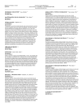
Clear Lexan barriers located in front of the main horizontal bus isolate
the bus from the top horizontal wireway. Maintenance personnel
can easily gain entrance to the top horizontal wireway of the control
center without danger of contact with a live bus.
An incoming-line terminal compartment can be located at the top or
bottom of a vertical section to allow cable termination with minimum
bending. The standard 600-ampere incoming line terminal compartment shown is furnished with mechanical type lugs. Other
incoming line terminal compartments are available for main bus
ampacities up to 2500 amperes.
Device bracket mounts 30mm pilot devices in Evolution Series.
Bracket swings open to allow easy access to unit components, wiring
and terminal blocks. Fully insulated – does not require grounding.
A polyester-reinforced “sandwich” insulates
and isolates the vertical bus and helps prevent
the spread of faults from starter and feeder
units to vertical or horizontal bus. Small stab
openings provide effective isolation. 65kA
short circuit bracing is standard for
Evolution Series MCC.
Plug-in stabs are rated 250A and 600A. The 250A stab connections
shown are made with copper unit power stabs which are under double
spring pressure and engage the vertical bus to provide positive contact.
All combination starters and feeder units of plug-in construction
utilize a positive guidance system.
High density two-piece, pull-apart control terminal boards feature
up to 18 points in 12” high units. External and internal unit connections are made on opposite sides, allowing the unit to be withdrawn
without disconnecting control wiring. Accommodates up to (2) #12
AWG wires with ring, fork or bare terminations. Rated 30 Amps, 600
Vac. Meets NEC Article 430.74.
New doors mounted on the case feature a removable hinge pin
providing easy door removal and accurate alignment.
A1
Evolution Series E9000 Motor Control Centers
General
A
Product Features
Design Features
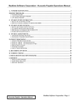
Large isolated wire trough provides a 4" x 11"
area to “lay in” wire and make control and
load connections. A separate removable door,
adjacent to drawout units, makes wiring
installation and inspection easy. The door
can be opened without disturbing adjacent
unit doors. 8" x 11" wire troughs are available
For flexibility, standard Size 1 and Size 2 FVNR starters are interchangeable in the same 12” high space unit. This design allows
quick, easy field changes when modifications are desired after
installation. Front accessible quarter-turn latches provide for ease
of securing and withdrawal of all plug-in units.
with 24" wide enclosures.
Units can be withdrawn to a disconnected
position and padlocked for maintenance.
A paint finish is applied to all un-plated steel parts. The powder
coating process withstands 1000 Hr. salt spray tests and provides
lasting protection.
An interlock release system is provided so that – if it becomes necessary for maintenance purposes – the disconnect may be closed
with the door open. A by-pass is provided to allow opening the door
with the disconnect closed. Only qualified personnel familiar with
the equipment should use the interlock release and by-pass features.
(Option) A vertical bus shutter mechanism can be supplied which
covers the vertical bus stab area when a plug-in starter or feeder is
withdrawn. Cap plugs are standard to close unused stab openings.
The vertically mounted integral handle can be locked in the OFF
position with up to three padlocks. A drilling pattern is furnished,
allowing the handle to be modified for locking in the ON position
with a single padlock. This modification should only be made after
the user determines it is desirable to lock the disconnect in the ON
position. Padlock to have maximum 3⁄8 ” shackle.
A2
(Option) Vertical Ground Bus and Unit Stab. Vertical copper ground
bus allows direct grounding of unit saddles to the equipment
ground bus. A unit ground bus stab engages the vertical ground
bus before the unit power stabs engage the vertical bus. A load
ground lug is available for customer cable grounding. Termination
points are located at the rear of the bucket, next to starter.
Evolution Series E9000 Motor Control Centers
General
Product Features
A
Design Features
E9000 MCC can be spliced onto existing 7700 Line, 8000 Line and
Spectra MCC for 1200A (supplied with 2" bars) and below. Horizontal
bus location in E9000 matches the existing bus location.
An optional snap-in steel barrier in the wireway provides added
isolation for low voltage signal wiring between units.
New oversized laser-engraved unit nameplates on 12” units and
larger feature 1 to 9 lines of up to 20 characters 0.18” high or 4
lines of up to 10 characters 0.30” high. Nameplates use Microsoft®
Windows® Arial font. Custom non-English characters are an option.
Lift up handle design to allow full access to fuses and CB rating
plug. Postion indication ON-TRIP-OFF.
Easily removable plastic knock-outs are provided in the vertical
wireway ladder assembly to allow routing of field wiring into units.
(Option) Motor terminal blocks can be supplied in Size 1 & 2 to
allow disconnecting motor wires when removing a unit. NEMA Type
BT wiring.
S-5 FVNR circuit breaker combination can be provided in 36”,
allowing two size 5 units in one section.
All case side wireways are roll-formed to provide a 1/2” lip for cross
wiring to rest on, thus preventing skinned insulation.
A3
Evolution Series E9000 Motor Control Centers
General
A
Product Features
Design Features
Drawing Software
Windows™-based Engineering Drawing System creates highquality detailed front, top, bottom and side views as well as
specific device information.
Size 1 FVNR Starter
50% smaller (1/2X)
NEMA rated compact C-2000 starter with 100VA CPT with up
to a quantity of three 22mm C-2000 pilot devices.
Horizontal Handles
Horizontal handles are standard on 6” 150A and 12” 250A
feeder breakers to optimize space. Optional vertical handles
are available, but they affect unit height.
Wire and Cable
Standard control and power wire includes flame-retardant,
(VW-1) moisture-heat-and oil-resistant thermoplastic insulation
rated 600 volts, with stranded copper conductors, types
MTW and THW.
Standard colors are:
Red – AC Control
Blue – DC Control
Black – AC/DC Power
Green – Ground
White – Neutral
Optional wiring available includes SIS heat-resistant synthetic
rubber-covered switchboard wire and XHHW flame-retardant
cross-linked synthetic polymer, both rated 600 volts with
stranded copper conductors, and a VW-1 flame rating (no PVC).
Note: Not all colors are available with optional wiring.
Nameplates
Unit service designation nameplates are furnished when
specified. Nameplates can be supplied as blanks suitable for
field engraving, or engraved at the factory.
Plug-in Stabs
The 600A stab shown uses a two-step engagement with vertical bus for low insertion/withdrawal force. Line side cables
crimped directly into spring reinforced tin-plated copper
stabs. No hidden line side cable in rear of units. Tapered
glass polyester stab mounting base gives positive plug-in
alignment with vertical bus.
The standard unit service designation nameplate is of 2-ply
thermoplastic material, black face with white core, 2 5/32" x 3
1/2", fastened with non-corrosive nylon clips. Plated steel
screws are available as an option.
Nameplates are engraved with white letters on a black
background using the Arial typeface found in Microsoft
Office applications. Standard nameplates carry up to nine
lines of .18" high characters (20 characters per line maximum) OR up to four lines of .30" characters (10 characters
per line maximum).
Six-inch units and the F-frame circuit breaker come with a
1"x 3" nameplate that accommodates up to three lines of
.18" characters with a maximum of 19 characters on lines 1
and 3 and 15 characters on line 2.
A4
Evolution Series E9000 Motor Control Centers
General
NEMA Class of Diagrams and Wiring
Motor control centers are classified by NEMA as
follows:
Examples of custom drawings are:
• Special identifications for electrical devices
• Special terminal numbering designations
• Special sizes of drawings
A
NEMA Class I Definition①
Class I motor control centers consist essentially of a mechanical
grouping of combination motor control, feeder tap and/or other
units arranged in a convenient assembly. They include connections from the common horizontal power bus to the units.
The drawings supplied by the manufacturer shall convey the
same information as drawings provided with Class I and II
motor control centers, additionally modified as specified by
the user.
They do not include interwiring or interlocking between
units or to remotely mounted devices, nor do they include
control system engineering.
When to Specify Class I
Specify NEMA Class I control centers for independently operated
motors requiring no interlocking or other interconnection
between units.
Diagrams of the individual units only are supplied.
NEMA Class II Definition①
Class II motor control centers consist of a grouping of
combination motor control, feeder tap and/or other units
designed to form a COMPLETE CONTROL SYSTEM. They
include the necessary electrical interlocking and interwiring
between units and interlocking provisions to remotely
mounted devices in addition to the connections from the
horizontal common power bus to the units.
The control manufacturer shall provide a suitable diagram
to illustrate operation of the control associated with the
motor control center.
NEMA Class IS and IIS Definition①
Class IS and IIS motor control centers shall be the same as
Class I and II motor control centers except custom drawings
shall be provided in lieu of standard drawings.
① From NEMA Standard 18-2001.
When to Specify Class II
When factory interconnections are desired to provide such
functions as sequencing and other interlocking or interconnection, the control centers required are NEMA Class II.
When to Specify Class IS and IIS
When custom drawings are desired to show special device
identification, special terminal numbering, or special diagram
size, etc. the control centers required are Class IS or IIS.
Wiring Type
The NEMA classes are sub-divided into A, B and C depending
on the type wiring furnished, with type B further having type
B-D for customer load wiring direct to the device and B-T for
customer wiring to a load TB (size 1 and 2 starters).
Note: For feeders and large starters, customer must wire direct to unit device terminals.
Note: In addition to NEMA prescribed wiring types, GE offers a NEMA 1A Modified MCC.
This type of MCC will be supplied without wiring and without control diagrams. GE can
mount low voltage control devices on the pilot device bracket and supply terminal
boards. This would be considered on OEM product.
Wiring Features by NEMA Classification
Type of Power or Control Termination Furnished
Pull-apart and numbered control terminal boards on unit starter–Sizes 1, 2, 3 and 4
Stationary and numbered control terminal boards on unit starter – Sizes 5, 6 and 7
Pull-apart and numbered power terminal boards on unit starter –Sizes 1 and 2.
(On Type A wiring: Same type of numbered terminals on starter itself for Sizes 1, 2, 3 and 4)
Numbered terminals on starter itself for power connection with no power terminal boards – Sizes, 5, 6 and 7
Stationary master terminal boards (Top, bottom or rear of section)
For control – Sizes 1 thru 5 / For power – Sizes 1 thru 3
Unit terminal boards for feeder tap units and distribution panels
Starter-unit-mounted pilot devices internally wired to starter – Sizes 1 thru 7
Terminal board points for remote devices (Excluding extra tie points)
Master terminal-board wiring connections
Factory-wired interconnections between units in the same motor control center
Type of Drawings Furnished
Outline and summary sheet (Schedule of units)
Unit elementary wiring diagrams showing numbered terminal points (Terminal boards
not furnished on Type A)
Unit elementary wiring diagrams showing numbered terminal points and interconnections
to other units and/or to the first level of remote devices
Schedule of wires to master terminal blocks
Custom drawings as specified by user
A
No
No
Class I
B
C
Yes Yes
Yes Yes
A
No
No
Class IS
B
C
Yes Yes
Yes Yes
Class II Class IIS
B
C
B C
Yes Yes Yes Yes
Yes Yes Yes Yes
No
Yes
Yes
Yes
Yes
Yes
No
Yes
Yes
Yes
Yes
Yes
Yes
Yes
Yes Yes Yes
Yes Yes Yes
No
No
Yes
No
No
No
No
No
Yes
Yes
No
No
Yes
No
Yes
Yes
Yes
No
No
No
Yes
No
No
No
No
No
Yes
Yes
No
No
Yes
No
Yes
Yes
Yes
No
No
No
Yes
Yes
No
Yes
Yes
No
Yes
Yes
Yes
Yes
No
No
Yes
Yes
No
Yes
Yes
Yes
Yes
Yes
Yes
Yes
Yes
Yes
Yes Yes
Yes
Yes
Yes
Yes
Yes
Yes
Yes
Yes
Yes Yes
No
No
No
No
No
No
No
Yes
No
No
No
Yes
No
No
Yes
No
Yes
Yes
Yes
No
No
Yes
Yes
No
Yes Yes
No Yes
Yes Yes
Yes
No
Yes
Yes
Yes
Yes
A computerized manufacturing process necessitates that the E9000 Line motor control center standard unit numbering system be followed to identify the section and location
of each unit. This is explained in detail in application data (Section J). It greatly simplifies wire tracing of interconnection wires, and is beneficial to the application of programmable control. The Outline and Summary drawing furnished with the equipment cross references the unit numbers and customer unit designations when specified.
A5
Evolution Series E9000 Motor Control Centers
General
A
Codes and Standards
Section Label
Motor control centers are manufactured to NEMA standard ICS 182001 and are eligible to receive the Underwriters Laboratories listing
mark under standard UL 845. Vertical sections and units which have
been listed with UL will bear the UL/cUL listing mark (see right for
examples). Since vertical sections and units are listed independently,
it is possible to have combinations of listed and non-listed sections
and units within the same control center. Sections and units which
will be shipped with the UL listing mark are identified in the appropriate sections of this publication.
The National Electrical Code covers installation of electric conductors
and equipment for installations identified in the NEC Article 90. The
NEC is not intended as a design specification and acceptance of an
installed motor control center by a local code authority is dependent
on factors independent of the equipment as shipped from the factory.
In general, equipment which bears the UL listing mark can be
installed to meet the NEC. Where 100 percent UL listed equipment
is mandatory or there are other special code requirements refer to
the factory for verification.
The NEC defines several types of control circuits and the over-current
protection required for each type. The following paragraphs provide
a general reference to the NEC Article applicable for the more
common control circuits.
NEC Articles 430.72(a) and (b) cover motor control circuits tapped
from the load side of a motor branch-circuit short-circuit protective
device (unit disconnect). Control circuit conductors from such a
tapped control circuit shall be protected in accordance with NEC
Table 430.72(b), which lists the maximum fuse or circuit breaker
rating vs. conductor size.
Motor control circuits other than such tapped control circuits (common
control transformers or external power source) shall be protected
against overcurrent in accordance with Section 725.12 or 725.35, as
applicable, for the type power source and field wiring conductor sizes.
Where a motor control circuit transformer is provided, the transformer should be protected in accordance with NEC Article 430.72(c).
Transformers other than motor control circuit transformers should
be protected in accordance with NEC Article 450.3(b).
A6
UL #E33752, Vol. 1, Sec. 5.
Unit Label
Evolution Series E9000 Motor Control Centers
General
Short Circuit Considerations
All ratings in this publication are RMS symmetrical amperes
Short-Circuit Current Ratings
The NEMA Motor Control Center Standard ICS 18-2001 defines
the short-circuit rating of a motor control center as follows:
“The motor control center short-circuit rating shall be the
maximum available rms symmetrical current in amperes
permissible at its line terminals. It shall be computed as the
sum of the short-circuit current contributions of the motors
connected to the motor control center and the maximum
available current, including all other short-circuit current
contributions of the supply system at the point of connection
to the motor control center.”
Motor Control Center Bus
trol center and sized per NEC A or 240 for horizontal bus
protection. Wherever located, it must have an interrupting
rating equal to or greater than the available short-circuit
current at the point of its connection to the system. If located
at the control center, this value would be the system available
short-circuit current, Is (Fig. 1).
A motor control center should be protected for all types of
faults from low-level arcing ground faults to bolted threephase faults which can develop the full available short-circuit
current. Line-to-line and line-to-ground arcing faults (often
produced by contaminated atmospheres, foreign materials,
etc.) can be appreciably lower in magnitude than the available
short-circuit current and must be assumed not to be selfextinguishing. Even low-level arching faults are capable of
releasing tremendous energy at the point of fault and can
be highly destructive.
A SPECTRA (MOLDED CASE SWITCH) OR A NON-AUTOMATIC
INSULATED CASE CIRCUIT BREAKER MUST BE PROPERLY
COORDINATED WITH UP STREAM PROTECTIVE DEVICES.
Fig. 1
Figure 1 illustrates simply the basis of determining the available short-circuit current. The individual short-circuit current
ratings of the main bus extensions, combination-controller
units and feeder-tap units must equal or exceed available
short-circuit current.
Is is the short-circuit current available from the system at the
point where the motor control center is connected. Im is the
short-circuit current contribution of the motors connected to
the motor control center. If exact information is lacking, the
motor contribution can be estimated at four times (4X) the
continuous-current rating of the main horizontal bus. Isc is
the available short-circuit current to be used as the basis for
selection. Thus: Isc = Is + Im.
High available short-circuit currents of modern distribution
systems require special consideration so that equipment
may be operated within its rating. The cost and operational
acceptability of the following should be carefully considered:
1. Use load-center distribution systems with smaller transformers which limit the available short-circuit current.
2. Use a current-limiting busway, reactors or higher-impedance
transformers to reduce the available short-circuit current.
3. Use current-limiting fuses, current-limiting breakers, or
breakers with limiters, in all combination starters and
feeders in the control centers.
Main Protective Devices
A motor control center requires adequate overcurrent and
short-circuit protection. This is the function of the main protective device. It may be located in or remote from the con-
For full protection against all levels of arcing faults on
grounded systems, a ground-fault relay is recommended.
The ground-fault system is a protective means that responds
to phase-to-ground current, but is not affected by phase-tophase current. It is used to protect motor control centers
from extensive damage, which can be caused by phase-toground arcing faults.
Fuses are single-pole interrupters. An arcing fault may not
necessarily be cleared by a single-pole interruption, as the
fault can be back-fed from the other energized phases. This
reduces the fault current, increasing the blowing time of the
energized fuses. Because of this delay, severe equipment
damage may occur. Single-phasing is eliminated with fastacting three-pole fused interrupter switches which open
when a single fuse blows.
An electrically operated HPC switch with single-phase detector
will meet the three-phase disconnection (single-phase
protection) recommendations for a main protective device.
When switches without a three-phase trip are used, an ITI
BGFL ground-fault protection scheme is particularly recommended since damaging arcing faults almost always involve
ground. It should operate the trip device on the closest
line-side three-phase disconnect.
Main Horizontal Bus and Vertical Bus Extensions
The standard bus short-circuit withstand rating is 65 kAIC
symmetrical amperes. Also available optionally is 100,000
rms symmetrical amperes. The bus rating must equal or
exceed the available short-circuit current. Refer to Structure
(Section B) for ratings.
A7
A
Evolution Series E9000 Motor Control Centers
General
A
Combination Motor Control Units
The short-circuit rating of a combination controller is based
on tests with rated short-circuit current available at the line
terminal of the control center and at rated voltage.
The short-circuit rating must equal or exceed the available
short-circuit current. Refer to Starters (Section D) for ratings.
Feeder Tap Units
All feeder tap units must have a short-circuit rating which
equals or exceeds the available short-circuit current. Refer
to Feeders (Section C) for ratings.
Fuse Classification
UL classifications are the most definitive method of determining
fuse characteristics, and are used in this publication. Use UL
fuse “Class” when specifying type of fuse.
UL classifications used in motor control centers are:
A. Class R – current-limiting type fuses with reject mounting
features. Class R fuses are sub-divided into Classes RK-1 and
RK-5, depending on maximum peak let-through currents.
RK fuses are rated 600 amperes maximum and 250 volts
or 600 volts.
B. Class J-TD – are more current limiting than RKs and due to
their unique dimensions have an inherent rejection feature.
Ratings are 600 amperes maximum, 600 volts. (Time delay
Class J-TD fuse may limit component damage under fault.)
C. Class L – are current limiting and due to their unique
mounting dimensions have an inherent rejection feature.
Ratings are 601 amperes minimum, 600 volts.
Fuses marked with “Time-Delay,” “Dual-Element” or similar
designations are time-delay type fuses and will generally
carry 500 percent rated amperes for 10 seconds, thus allowing
a smaller rated fuse to be used in most starter applications.
UL listed combination motor starter units used with Class H,
K-1 or K-5 fuses are short-circuit rated 5kA for NEMA size 1, 2
and 3 starters, and 10kA for larger starters. Higher short-circuit
ratings require rejection type fuses. See Fuse Classifications
table below for short-circuit ratings.
Fuses that are mechanically interchangeable may not be
electrically equivalent. Refer to the fuse manufacturer for
interrupting rating and current-limiting characteristics.
Fuse Classifications
Characteristic➀
Ampere Range
Voltage Ratings
Interrupting
Rating RMS
Symmetrical Amperes
Current-Limiting
UL Standard
Class J-TD Class R Class L
0-600
0-600 601-6000
600
250
600
600
200K
200K
200K
Yes
Yes
Yes
① Check fuse manufacturers for specific fuse characteristics
A8
Environmental Considerations
The standard E9000 motor control center is designed for
operation in a clean, indoor environment having a 40°C
maximum ambient temperature.
The nominal minimum temperature for storage is -40°C and
for operation, -20°C. Motor control center space heaters are
recommended whenever temperature conditions below 0°C
will exist. Where extreme cold temperatures are to be encountered for long periods of time. It is recommended that the
motor control center be installed in heated rooms or enclosures.
For ambient temperatures above 40°C, special consideration
must be given to the need for ventilation, ambient-compensated breakers and overload relays, special wire insulation
and oversized control transformers. Ambient compensated
overloads provide essentially constant trip setting as the
control ambient varies.
For indoor environments subject to falling liquids, NEMA 2
dripproof enclosures are recommended. If water spray and
splashing are to be encountered, NEMA 2 construction should
also be used. Space heaters may be desirable to prevent
condensation on internal parts.
For outdoor installations, NEMA 3R non-walk-in weatherproof
enclosures are required. Thermostatically controlled space
heaters and ambient-compensated breakers and overload
relays should be considered for these applications. Provisions
for heating and cooling the entire outdoor enclosure are also
available. Standard NEMA 3R construction is suitable for wind
velocities up to 75 mph. Beyond this, up to 130 mph, specially
reinforced enclosures are available through SEPS. This special
design is also necessary if the NEMA 3R enclosure has to withstand seismic conditions, including seismic Zone 4 applications.
E9000 motor control center is available for earthquake conditions.
It can satisfactorily withstand a force of 5 g’s, 1 to 100 Hz, input
at its floor sills simultaneously in all three orthogonal axes, and
is rated for UBC/C Seismic Zone 4 installation. It is IBC-2003 rated.
For dusty atmospheres, semi-dust-tight NEMA 1 gasketed or
NEMA 12 construction are recommended.
The altitude limit for the standard electro-mechanical motor
control center design is 6000 feet. Applications above this
should be referred to the Company for recommendations.
Some solid-state components are only rated to 3300 feet
and may reduce the altitude limit of the motor control center.
Fungus-proofing of organic materials is inherent. Keeping equipment dry and above the dew-point is the best way of avoiding
fungus-growth, and the use of space heaters is recommended
for this purpose. Heaters should be energized if the motor control
center is to be stored for any length of time. Where export crating
is involved, terminals for connection of an external source of
space heater power can be provided on the outside of the crate.
Evolution Series E9000 Motor Control Centers
Structure
NEMA Enclosure Types
E9000 Indoor Enclosure
Type 1 – General Purpose, Indoor
Intended for use indoors, primarily to prevent accidental
contact of personnel with the enclosed equipment, in areas
where unusual service conditions do not exist. In addition,
they provide protection against falling dirt.
GE motor control centers are made up of standardized vertical
sections housing vertical and horizontal bus, wiring channels
and compartmented control units. Sections may be bolted
together to form a single panel assembly powered by line
connection at a single point. Normal shipping split is three
sections maximum.
Type 1 – Gasketed – Semi Dust-tight, Indoor
Intended to cushion doors and mitigate vibration.
Type 2 – Drip-proof, Indoor
Intended for use indoors to protect the enclosed equipment
against falling noncorrosive liquids and falling dirt. These
enclosures have provision for drainage. Dripshields on top of
the motor control center and neoprene closed-cell gasketing
afford protection from falling and splashing liquids. They are
not water-tight.
Type 3R – Rain-proof, Outdoor
Intended for use outdoors to protect the enclosed equipment
against rain. They are not dust-proof, snow-proof nor sleetproof (ice-proof).
Type 12 – Industrial Use – Dust-tight and Drip-tight, Indoor
Intended for use indoors to protect the enclosed equipment
against fibers, flyings, lint, dust and dirt, and light splashing,
seepage, dripping and external condensation of noncorrosive
liquids.
Standard NEMA 1 or NEMA 1 (Gasketed) Enclosures
Standard finish is light-gray ANSI 61 over a phosphate rust
inhibitor. All unpainted parts are zinc-chromate electroplated
or galvanized. Enclosures are furnished with bolt-on rear
covers. Hinged rear doors are available as an option. Pan-type
doors utilize quarter-turn fasteners. Gasketed doors, cover
plates, and operating handles are available as an option.
Two heavy-duty 3" by 1 1/2", 12-gauge floor sills and 1/4"
structural lifting lugs are included. Open bottom is standard.
NEMA 2 Drip-proof Construction
Similar to NEMA 12 gasketed construction except with catch
pan-type dripshield on top and with open bottom. Dripshield
extends four inches beyond front of motor control center.
Standard finish: light gray ANSI 61. Furnished with removable
conduit cover plates unless otherwise specified.
NEMA 12
Similar to NEMA 1 gasketed construction except that bottom
plates are furnished and all removable plates are gasketed.
B1
B
Evolution Series E9000 Motor Control Centers
Structure
Indoor Enclosures
Front Elevation & Mounting Locations (13", 20", 22" & 25" Deep Sections)
B
B2
Evolution Series E9000 Motor Control Centers
Structure
Indoor Enclosures
Side Elevations 13" Deep Section 600A to 1200A Main Bus
B
Side Elevations 20" Deep Section 600A to 1200A Main Bus
B3
Evolution Series E9000 Motor Control Centers
Structure
Indoor Enclosures
Side Elevations 25" Deep Back-to-Back Section 1200A Main Bus
B
Side Elevations 22" Deep Section 1600A to 2500A Main Bus
B4
Evolution Series E9000 Motor Control Centers
Structure
Indoor Enclosures
Side Elevations 25" Deep Back-to-Back Section 1600A to 2500A Main Bus
B
Top Conduit Entry (13", 20", 22" & 25" Deep Sections)
B5
Evolution Series E9000 Motor Control Centers
Structure
Indoor Enclosures
Bottom Conduit Entry 13" Deep Section
B
Bottom Conduit Entry 20" Deep Section
B6
Evolution Series E9000 Motor Control Centers
Structure
Indoor Enclosures
Bottom Conduit Entry 22" Deep Section
B
Bottom Conduit Entry 25" Deep Section
B7
Evolution Series E9000 Motor Control Centers
Structure
Indoor Enclosures
Elevation and Mounting 30" Deep Section 600A to 1200A Main Bus
B
Top Conduit Entry 30" Deep Section
B8
Evolution Series E9000 Motor Control Centers
Structure
Indoor Enclosures
Bottom Conduit Entry 30" Deep Section
B
Details for Auto Transformer
B9
Evolution Series E9000 Motor Control Centers
Structure
Indoor Enclosures
Drip Pan — Nema II 13" Deep Section
B
Drip Pan — Nema II 20", 22", 30" Deep Sections
Drip Pan — Nema II 25" Deep Section Back-to-Back
B10
Evolution Series E9000 Motor Control Centers
Structure
Indoor Enclosures
Type C Master Terminal
B
Used for L and U Shaped Motor Control Center Arrangements
B11
Evolution Series E9000 Motor Control Centers
Structure
Indoor Enclosures
Incoming Line Terminations
B
B12
Evolution Series E9000 Motor Control Centers
Structure
Indoor Enclosures
B
B13
Evolution Series E9000 Motor Control Centers
Structure
Outdoor Enclosures
B
UL Listed Type 3R Non-Walk-In Enclosure (Standard)
The standard NEMA 3R enclosure consists of a specially
constructed MCC section with a mating framework which
supports the roof and extended front. The basic design is
similar to switchboard construction. The smaller footprint
will permit a broader usage than the optional NEMA 3R
construction. Meets Seismic Zone 4.
B14
• Three-point door latch
• 90° door with wind stop
• Reinforced roof
• Crane lifting
• 2° roof pitch
• Shipped via flatbed truck
• 3" floor sills
Evolution Series E9000 Motor Control Centers
Structure
Indoor Enclosures
Options
Extra Width Vertical Wireway
24" wide sections can be furnished with 8" wide vertical
wireway and door.
Space Heaters
Space heaters are used to prevent moisture condensation on
the inside of the motor control center. One heater (62.5 watts
at 120 volts AC) is installed in the bottom of each vertical
section. UL requires space heaters be controlled by a thermostat. One thermostat can control up to 14 heaters and is
located in the top horizontal wireway.
B
A terminal board for connecting an external 120-volt power
source is standard. The terminal board is located in the top
horizontal wireway adjacent to the thermostat(s). This is
recommended since it permits the space heaters to be energized
even when the motor control center itself is deenergized. If
export crating is involved, the space heater circuit can be
wired to an external plug for energizing the heaters during
shipment and storage.
When specified, space heater power can be provided from
within the motor control center. Include the required distribution
transformer with primary and secondary protection in the
motor control center.
An enclosed foreign voltage disconnect switch is available
as an option.
Bottom Plates
Plates bolt on to the bottom of each motor control center
section. They may be removed to facilitate installing conduit.
Extended Height Pull Box (Top Hat)
A pull box can be mounted on top of a vertical section when
specified. The standard height is 12 inches; 6-, 18-, and 24"
heights are also available. Top, front, and end covers are
removable for access.
Rodent Barriers
Metal plates bolted to the bottom of each end section to close
the opening between the front and rear floor sills. Not required
if the floor sills will be removed or imbedded in concrete.
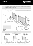
Indoor enclosure, exploded view
Motor Control Center Construction
Major Structural Components Side Sheets,
L-H & R-H
0.075"
Vertical Bus Mounting Channels
0.090"
Case Sills, Front/Rear, Top/Bottom
(13 Gauge)
Top Horizontal Channel
Lifting Channel (Top)
0.187"
Channel Sills, Front/Rear
0.105" (12 Gauge)
Enclosing Covers/Panels
Rear Covers, 13" & 30" Deep
0.075" (14 Gauge)
Rear Covers, 20" & 22" Deep
0.060" (16 Gauge)
Endplates
0.060" (16 Gauge)
Top Conduit Covers
0.060"
Bottomplates
0.060"
Vertical Wiretrough Door
0.060"
Other Steel
Unit Barrier Shelves
0.063"
Unit Cover Doors
0.075"
Unit Saddles
0.090"
B15
Evolution Series E9000 Motor Control Centers
Structure
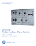
Center of Gravity
Indoor Enclosures
Note that bolt down locations for sections with seismic bracing
change from center of structure (left to right), to four corners
with .635 clearance holes for 1/2" bolts.
Y
20"
Z
X
B
Mounting Requirements for Seismic NEMA 3R with
Optional Heavy Base
ARC
WELD
91.5"
ARC WELD ALL FOUR
CORNERS (3/16" BEAD)
NEMA 3R
END VIEW
FRONT VIEW
DOWN
NEMA 3R
FRONT VIEW
6" CHANNEL
ANCHORED
10" MIN.
WELD
TION
MIN. 8" H BEAM
ANCHORED FRONT
AND REAR
40" OR LESS
6" MIN.
WELD
10" MIN.
WELD
CEMENT PAD
ARC WELD DOWN LENGTH OF NEMA 3R EVERY 40" OR LESS
FOR 130MPH WINDS AND 2.25G SHOCK (LENGTH & DEPTH PER OUTLINE)
Note:
Seismic Zone 4 testing was performed using 1/2"-13 Grade 5 bolts, torqued to
70 foot-pounds, located in each of the four corners in each section.
Estimated shipping weights per section
Sections
Lbs
Kg
90"H x 20"W Indoor Nema 1 & 12
600
272
90"H x 20"W Indoor Back-to-Back Nema 1 & 13
700
318
90"H x 20"W Outdoor Nema 3R
725
329
B16
For a uniformly loaded 90" high x 20" deep lineup,
center of gravity is:
X =
Y =
Z =
OR:
Z =
Z =
Z =
center of lineup
46 1/2" above bottom of floor sill
8" in from front (front-mounted devices 20" deep)
10" in from front (back-to-back construction)
5" in from front (13" deep)
8 1/2" in from front (22" deep)
11" in from front (25" NEMA 3R)
Typical variations due to uneven loads:
X = ± 5"
Y = ± 1"
Z = ± .5"
Evolution Series E9000 Motor Control Centers
Structure
Bus Selection
All continuous-current rating selections or recommendations
are based on the motor control center being located in a
maximum 40° C (104°F) ambient. Refer to General (Section A)
for other environmental considerations.
Main Horizontal Bus
The size of motor control center main bus and cables feeding
the main bus is based on the current-carrying capacity
required for motors plus other connected loads.
The capacity required for motors can be taken as 125 percent
of the full-load rating of the largest motor plus 100 percent
of the full-load rating of all other motors to be operated at the
same time. Modified requirements resulting from duty-cycle
or demand factor can be taken into account.
The current-carrying capacity required for other connected
loads should be computed on the basis of 100 percent of
the sum of individual loads except where a demand factor
can properly be applied to reduce this total. Consideration
should be given to future requirements.
Vertical Bus Extensions
Vertical bus is available in 30" wide enclosures maximum.
The maximum vertical bus loading is calculated as follows:
80 percent of the feeder trip or fuse clip rating, plus 100
percent of the starter full load amps, plus 25 percent of the
largest motor full load amps. This total cannot exceed the
vertical bus rating. Tin plated copper vertical bus is standard,
with silver plating as an option.
Neutral Bus
Neutral lugs will be provided as applicable. Neutral bus is
normally sized at 50 percent of the main bus ampacity.
Ground Bus
NEC requires a ground bus in multisection motor control
centers. 300 ampere Cu ground bus will meet minimum size
requirements for main busses rated through 2000 amperes.
A clearance hole for 3/8" hardware is provided in each section.
The default for incoming ground termination is (3) #2-1/0 for
300A ground bus and (3) 1/0-500 kcmil for 600A ground bus.
Ground bar comes with 6 predrilled holes for ground
connectors.
Options
The following UL listed options are available:
• Shutter mechanism for vertical bus stab openings.
• Fully-insulated main horizontal bus.
• Silver plated horizontal and vertical bus.
• Silver plated ground bus.
Bus Systems/Selection
Short-Circuit Rating in RMS
Symmetrical Amperes–(kA)
65
100
Continuous CurrentÄ
Rating Amperes
Material
Cu
600
800
1200
1600À
2000À
2500ÀÂ
X
X
X
X
X
X
X
X
300Á
600/850Ã
X
X
X
Neutral
300
600
800
1200
1250
X
X
X
X
X
X
X
X
X
X
Horizontal Ground
300
600
X
X
X
X
1/4" x 1"
1/4" X 2"
Vertical Grounds
150
X
X
1/8" x 1"
MCC Bus
Main Horizontal
Vertical
UL
Notes
X
X
X
X
X
X
X
X
X
X
1/4" x 2" Bus
3/8" x 2" Bus
1/2" x 2" Bus
(2) 1/2" x 2" Bus
(2) 1/2" x 2" Bus
(2) 1/2" x 2" Bus
X
X
X
3/8" x 3/4"
3/8" x 1 1/2"
All values shown based on 1200A/sq.in. density rating. Alternate density ratings are available; if required, consult factory.
À
Á
Â
Ã
Ä
Requires a 22" deep section.
Will not except 600A stabs.
Provided with fans.
1200A horizontal or higher.
Bus ratings based on UL Temperature Rise testing.
B17
B
Evolution Series E9000 Motor Control Centers
Mains, Feeders, Incoming Lines
Mains
General
Main units consist of an externally operable circuit disconnect,
either a fusible switch or a circuit breaker. Sizes by ampere
rating, short-circuit rating, type construction and space units
required are given in the accompanying lists.
Normally, thermal magnetic circuit breakers or fuses are
necessary for main protection. The short-circuit interrupting
rating depends on the type disconnect furnished. Select a
main unit for which the interrupting rating equals or exceeds
the maximum available fault current.
For reverse-fed circuit breakers, refer to factory for details.
Fused Switch Mains
Interrupting Rating
RMS Amps
Amperes
(In thousands)À
Volts
240
480
600
Fusible Switches
200
100
100
100
400 MCS 100
100
100
600 MCS 100
100
100
High Pressure Contact Switch
800
100
100
100
1200
100
100
100
1600
100
100
100
2500
100
100
100
Construction
StabIn
BoltIn
X
UL
Space
Units Listed
Notes
X
X
2
4
4
X
X
X
Ã
Ã
X
X
X
6
6
6
X
X
X
X
6
X
Á
Á
Â
Â
C
À With Class J, R and L fuses.
Á Requires a 24" wide by 20” deep section. Full depth of enclosure is required.
 Requires 30" wide by 30" deep section. Must be NEMA 1 Construction, 80% rated only.
à Class J fuse is 3X.
Refer to specific breaker publications for time-current characteristics and programmable options for the various types
of circuit breakers. A list of these publications is given in
Application Data (Section J).
Service Entrance
UL listed main units containing only circuit breakers or fused
switches may be UL classified as suitable for service entrance.
If a single disconnect is furnished as a disconnect for all
load circuits the unit will be marked “Main”.
In order for the units to be classified as suitable for service
entrance, the incoming phase conductors must connect
directly to the disconnect device line terminals or to a UL
listed main line terminal assembly.
A grounding electrode conductor terminal connector sized in
accordance with the circuit ampacity is furnished in one
section. Three-phase, four-wire systems include a neutral
bonding jumper for grounding the neutral conductor during
installation. Ground fault protection is required for disconnects 1000A and above for solidly grounded wye services,
where phase-to-ground is more than 150 volts (NEC 230.95).
Main Metering/Lugs
Line side CTs can be provided in the main compartment for
use with a metering unit. This option in some cases will add
space.
If crimp type lugs are required, a bus assembly is fabricated
to provide a landing pad for these terminals. This extends
the space required for the main and must be factory
installed. Size will be the same as NEMA lug option.
C1
Evolution Series E9000 Motor Control Centers
Mains, Feeders, Incoming Lines
Mains
Circuit Breaker Mains – Standard Selection
CB
Type
240V
Spectra Thermal Magnetic
150
SEL/SEP
65/100
250
SFL/SFP
65/100
600
SGL/SGP
65/100
1200
SKL
65
Power Break® Insulated-Case MicroVersaTrip
800
SSF/SHF
65
1200
SSF/SHF
65
1600
SSF/SHF
65/100
2000
SSF/SHF
65/100
2500
SSF/SHF
65/100
800
SSD
65
1600
SSD
65
2000
SSD
65
Conventional, Thermal Magnetic
150
THED
30
Limiter Assisted, Thermal Magnetic
100
THEDL
–
Amperes
C
IC (kA)
480V
600V
65/100
65/100
65/100
65
25/25
25/25
65/65
42
65
65
65/100
65/100
65/100
65
65
65
42
42
42/65
42/65
42/65
42
42
42
25
–
StabIn
BoltIn
Space
Units
UL (X)
Listed
X
1
11⁄2
2
3.5
X
X
X
X
ÀÄ
T/B
T/B
T/B
T/B
X
X
X
6 (24W)
6 (24W)
6 (30W)
6 (30W)
6 (36W)
6 (30W)
6 (30W)
6 (30W)
X
X
X
X
X
–
–
–
Á
Á
Â
ÂÅ
ÂÅ
ÅƳ
ÂÅƳ
ÂÅƳ
T/B
T/B
T/B
T/B
T/B
T/B
T/B
T/B
18
X
11⁄2
X
T/B
100
X
1
X
T/B
X
X
X
X
X
X
X
X
Notes
Entry
Top/Bot
À When a size 6 or 7 starter is in the motor control center lineup, use a 1200 ampere MicroVersaTrip circuit breaker as a main.
Á Requires special section 90" high, 24" wide, 20" deep
 Requires special section 90" high, 30" wide, 30" deep.
à Requires full 20" depth of enclosure; rear is not available for back-to-back construction.
Ä Main breaker must be mounted at top of the section and requires full 20" depth of enclosure.
Å Requires special section 90" high, 30" wide, 30" deep. When section is on the left, allow for a 5" spacer to permit unit doors on the right to open.
Æ For UL or service entrance labels provide main breaker in switchboard construction.
³ Consult factory for availability.
Data subject to change without notice
Ground-Fault Protection of Equipment per NEC
Each main or feeder disconnect rated 1000 amperes or more
and installed on a solidly grounded wye electrical system of
more than 150 volts to ground, but not exceeding 600 volts
phase-to-phase, shall be provided with ground-fault protection
of equipment.
Exception No 1: The above is not required if the disconnect
is for a continuous industrial process where a non-orderly
shutdown will introduce additional or increased hazards.
Exception No 2: The above is not required for fire pumps.
Exception No 3: The above is not required if ground-fault
protection is provided ahead of the equipment.
Note: The above is paraphrased from NEC section 215.10, 215.95 and 240.13.
C2
Evolution Series E9000 Motor Control Centers
Mains, Feeders, Incoming Lines
Feeders
Feeder units consist of an externally operable circuit disconnect, either a fusible switch or a circuit breaker. Thermal
magnetic circuit breakers are required unless the feeder
supplies a critical circuit, such as a fire pump controller.
Select the fuse or circuit breaker trip rating based on the
feeder circuit continuous current rating in accordance with
the NEC. Feeder unit short-circuit interruption ratings must
equal or exceed the available short-circuit currents.
C
Fused Switch Feeders
Interrupting Rating
RMS Amps
Construction
Amperes
(In thousands)À
Stab- BoltVolts
240
480
600
In
In
Fusible Switches
30
100
100
100
X
30/30
100
100
100
X
60
100
100
100
X
60/60
100
100
100
X
100
100
100
100
X
100/30
100
100
100
X
100/60
100
100
100
X
100/100 100
100
100
X
200
100
100
100
X
400 MCS 100
100
100
X
600 MCS 100
100
100
X
THPR High Pressure Contact Switch
800
100
100
100
X
1200
100
100
100
X
100
X
1600Ã
100
100
Space
UL
Units Listed
À
(X)
1
1
1
1
1.5
1.5
1.5
1.5
2
3
3
X
X
X
X
X
X
X
X
X
X
X
6
6
6
X
X
–
Notes
Á
Á
Â
Â
Â
À Top/bottom entry.
Á Dual or twin feeder units.
 Requires a 24" wide by 20" deep section. Full depth of enclosure is required.
à Requires a 30" wide by 20" deep section. Full depth of enclosure is required.
C3
Evolution Series E9000 Motor Control Centers
Mains, Feeders, Incoming Lines
Feeders
Circuit Breaker Feeders – Standard Selection
Amperes
C
CB
Type
Spectra Thermal Magnetic
100
SEL/SEP
100/100
SEL/SEP
150
SEL/SEP
150/150
SEL/SEP
250
SFL/SFP
250/250
SFL/SFP
600
SGL/SGP
1200
SKL
Conventional, Thermal Magnetic
100
THED
150
THED
240V
IC (kA)
480V
600V
StabIn
65/100
65/100
65/100
65/100
65/100
65/100
65/100
65
65/100
65/100
65/100
65/100
65/100
65/100
65/100
65
25/25
25/25
25/25
25/25
25/25
25/25
65/65
42
X
X
X
X
X
X
X
30
30
25
25
18
18
X
X
BoltIn
Space
Units
UL (X)
Listed
X
1/2
1
1/2
1 1/2
1
2
2
3.5
X
X
X
X
X
X
X
X
1/2
1
X
X
Notes
Entry
Top/Bot
Á
Á
ÂÃ
À
T/B
T/B
T/B
T/B
T/B
T/B
T/B
T
T/B
T/B
À When feeder unit accessories are required such as shunt trip, AUX switch, UV release, etc., unit height must be a minimum of 1 space.
Á 1X units are available with horizontal handle.
 Requires full depth of enclosure; (20" deep minimum).
à Feeder units 1000A and over should have ground fault sensing on three-phase, four-wire systems where line to ground voltage is more than 150V.
Options for Mains and Feeders
Accessories for Spectra Molded Case Circuit Breakers
Breaker Type
Bell Alarm
All Spectra
Left Pole
Shunt TripÀ
or Undervoltage Release
Left Pole
Aux. SwitchÁ
Total # of Accessories
Right Pole
Aux. Switch & Bell Alarm Plus 1 other
Accessories for Power Break
Breaker Type
SSF, SHF
Bell Alarm
Switch
UL
Auxiliary
Switch
ULÂÃ
Shunt
Trip
UL
Undervoltage
Release
UL
À Shunt trip requires aux. switch (G&K) or bell alarm (E&F) for continuous operation.
Á Aux. switch available @ 240V max only.
 600V AC aux. switches are not UL Listed.
à Maximum number of SPDT aux. switch elements is 10 when shunt trip is used, 12 without shunt.
Ä UVR and blown fuse trip cannot be installed simultaneously.
C4
Blown Fuse
Trip
UL
Electrical
Operator
UL
Total No. of
Accessories
AllÄ
Evolution Series E9000 Motor Control Centers
Mains, Feeders, Incoming Lines
Options for Mains and Feeders
Terminals for Field Wiring Mains and Feeders
Will Accept WireÁ
AWG/kcmilÀ
Material
Terminal Size
Switches
30A QMW
60A QMW
14-8
14-2
12-2
14-1/0
12-1/0
(1) 6-250
(1) 2-350Â
100A QMW
200A QMW
400A MCS (Molded Case Switch)
(2) 6-500
Cu-Al
Cu
Al
Cu
Al
Cu-Al
Cu-Al
Cu-Al
Cu-Al
Cu-Al
Cu-Al
300-750
300-800
Cu
Al
12-3/0
8-350
6-600
2/0-500
3/0-500
300-750
250-400
14-8
13-3
6-2/0
4-2/0
2-3/0
1/0-300
Cu-Al
Cu-Al
Cu-Al
Cu-Al
Cu-Al
Cu-Al
Cu-Al
Cu-Al
Cu-Al
Cu
Al
Cu-Al
Cu-Al
(1) 8-600
(1) 8-600
(1) 4-500Â
600A MCS (Molded Case Switch)
HPC Switch
800-1600A
Circuit Breakers
SE150 15-150A
1 lug
SF250 70-225A
1 lug
SG600
1 lug
125-600A
2 lugs
SK1200
3 lugs (800A)
300-1200A
3 lugs
4 lugs
THED
15-30A
THEDL (100A Max) 35-60A
70-110A
70-110A
125-150A
Ground Lug
À Conductor #1 and smaller may be noted 60/75°C. Conductors #0 and larger must
be rated 75°C.
Á Conductor sizes based on 1/Ph unless otherwise indicated.
 Feeders.
Accessories for Fused Switches
Switch Rating
30
60
100
200
400
600
1 NO
UL
UL
UL
UL
UL
UL
Auxiliary Contacts
1 NC
2 NO
UL
UL
UL
UL
UL
UL
UL
UL
UL
UL
UL
UL
1 N0, 1 NC
UL
UL
UL
UL
UL
UL
Note: Aux. contacts listed above are shown with fused switch in the open position.
Accessories for High Pressure Contact Switches
• Integral ground fault with three-phase sensor adjustable
pick-up, adjustable time-delay, test function, mechanical
ground fault indicator.
• Integral ground fault with three-phase sensor and relay
only (without test function, without indicator).
• Integrally mounted three-phase current sensor and 120
volt AC electric trip only, for use with ITI BGFL relay and
monitor panel.
• Blown fuse protection (480 volts max.)
• 1,2,3 or 4 SPDT auxiliary switches rate 6 amperes, 240
volts AC.
C
Key Interlocking
Provisions for key interlocking can be provided on all circuit
breakers over 250A and fusible switches over 100A. The
standard key lock is by Superior Lock Corporation. However,
coordination with Kirk key locking will be supplied if necessary.
The following information is required when lock coordination
is to be provided with other up-stream or down-stream
devices remote from the motor control center:
PURCHASED BY ________________________________
ULTIMATE USER ________________________________
DESTINATION __________________________________
LOCK MANUFACTURER __________________________
LOCK NUMBER_________________________________
PURCHASE ORDER NUMBER______________________
Note: Minimum 24" high units are required for key interlocking. UL listed option.
Ground Fault Protection
Two types of UL listed ground fault protection can be provided as
an option with feeder and main circuit breakers. A shunt trip device
is required in the circuit breaker to trip the breaker if a ground fault
should occur. ITI BGFL ground break protective relaying is recommended
for main breaker application. Model #252 ground fault relaying is
recommended for most feeder applications. See Components
(Section H) for description of both ground fault relay types. A minimum of 12" additional space height is required in addition to the
standard space height shown for each main feeder unit.
A separate 120-volt source for the shunt trip circuit will decrease
the additional space required.
Refer to page J19 for application help.
C5
Evolution Series E9000 Motor Control Centers
Mains, Feeders, Incoming Lines
Incoming Line Terminations
The following cable terminal compartments are commonly
specified for use in motor control center construction where
the main AC power disconnect is located upstream of the
motor control center.
For other custom cable termination arrangements refer to
Company. The number of cables indicated must not be
exceeded to maintain the short-circuit rating.
C
MLO Space in inches /
Incoming Line Cable Vertical Space Available
Assemblies
Top
Bottom
18/66
18/66
600A Std. LugÃÄ
24/54
24/54
30/48
18/66
600A NEMA LugÁ
30/48
24/60
24/54
800A/1200A
24/60
24/54
GE Std. LugÀÃ
30/54
24/54
30/48Å
800A/1200A NEMA
Lug
36/58
36/42
1600A NEMA Lug
72/0
72/0
2000A NEMA LugÁÃ 72/0
72/0
2500A NEMA LugÁÃ 72/0
72/0
Cable Range Per
Cables/lug Cables/phase
NEMA BendingÆ
Minimum Top Feed
Width &
Conduit Space
Depth
(Fig.1)
2
3
2
3
1
1
1
4
3
4
1
1
1
1
1
20"x13"
20"x13"
20"x13"
20"x13"
20"x13"
20"x13"
20"x13"
20"x13"
20"x13"
20"x13"
24"x13"
24"x13"
30"x30"
30"x30"
36"x30"
2
3
2
3
2
2
2
4
3
4
4
4
8
8
10
#2-350 kcmil
#6-300 kcmil
#2-600 kcmil
#2-500 kcmil
#2-600 kcmil
#2-350 kcmil
#2-600 kcmil
#2-500 kcmil
#2-600 kcmil
#2-600 kcmil
500-750kcmil
500-1000kcmil
500-1000kcmil
500-1000kcmil
500-1000kcmil
5"x13.7" A-B
5"x13.7" A-B
5"x13.7" A-B
5"x13.7" A-B
5"x13.7" A-B
5"x13.7" A-B
5"x13.7" A-B
5"x13.7" A-B
5"x13.7" A-B
5"x13.7" A-B
5"x13.7" A-B
5"x13.7" A-B
13"x17.7" A-C
13"x27.6" A-C
13"x27.6" A-C
À Space shown above is for 20" deep design 800A to 1200A MLO.
Á Burndy type YA crimp lugs is available as an option. Crimp Lugs require NEMA drilling and NEMA Lug spacing.
 Mechanical compression Cu/Al Lugs furnished for 75°C cable.
à Cu/Al standard. Copper only lugs are available as an option. These may affect number of cables per lug.
Ä NEMA wire bending rules reduce cable size if entry is from the side.
Å 13" deep requires full section no vertical bus.
Æ Lug cable range may be larger than the NEMA bending allows above.
Fig. 1
A
B
C
Busway Entrances
GE motor control centers include provisions for connecting
GE busways. Busways must be braced for maximum available
short circuit current. Minimum enclosure sizes for busway
are shown in the adjacent table. Refer to the factory for
other type busway. Include busway requisition number
when ordering Motor Control Center.
Spectra Series Busway
Entry
Top
Bottom
Top
Bottom
Top
Bottom
Pull Box Enclosure Size
12"
–
12"
–
12"
–
30"W x 22"D
30"W x 22"D
30"W x 22"D
30"W x 22"D
36"W x 22"D
36"W x 22"D
Std
1600
1600
2000
2000
2500
2500
Max. Busway Ampacity
Cu
Al
1000A/IN2
Std
750A/IN2
1500
1350
1000
1500
1350
1000
2000
2000
2000
2000
2000
2000
2500
2500
2500
2500
2500
2500
Note: Bus bars must be phased front-to-rear in 24" width enclosure. Bottom entry
requires full section. For busway, refer to factory.
C6
Evolution Series E9000 Motor Control Centers
Mains, Feeders, Incoming Lines
DS
Automatic Transfer Switches
GE motor control centers may be furnished with GE Zenith
transfer switches. The switch is mounted in a separate unit
and cable-connected to the motor control center bus.
Manual control, pushbuttons, pilot lights and switches may
be door-or bracket-mounted within the unit. Up-stream
overcurrent protection must be provided for each power
source. The unit can be UL listed if all components are listed
for use in motor control center equipments.
The following features apply to ZTSD open-type switches
which are UL listed through 480 volts and CSA listed through
600VAC. For specific ratings and additional optional features
refer to GE Zenith.
GE Zenith ZTSD Utility to Generator time delay MX 250
Module Standard Features:
6P
A3
Microprocessor activated test switch (momentary)
Aux Contact - closed in emergency (Source 2)
Additional available up to 10, must be specified
Aux Contact - closed in normal (Source 1)
Additional available up to 10, must be specified
Exerciser no load timer
A4
CDT
Disconnect Switch for source voltage to transfer
power panel, 600A to 1200A only
DT
Time Delay from Neutral Switch position to Source
1 on retransfer
DW
Time Delay from Neutral Switch position to Source
2 on retransfer
E
Engine Start Relay
EL/P
Event Log of last 16 events
K/P
Frequency Indication on the controller
LNP
Center-off position LCD-Indicator
L1,2,3,4 LED lights, Source 1&2 position, Source 1&2 available
P1
Engine Start Timer (adj. To 6 sec.)
R50
In Phase monitor between Normal (Source 1) and
Emergency (Source 2) to allow transfer
S13P
Microprocessor activated commit/no commit on
transferring to Emergency (Source 2) (with
enable/disable settings)
T
Retransfer to Normal (Source1) adjustable time delay
U
Engine stop / cool down timer
V1
Voltage imbalance between phases (3 phase only)
W
Adjustable time delay on transfer to Emergency
(Source2)
YEN
Bypass transfer timers function (soft key switch in
microprocessor )
Withstand Current Ratings (WCR) for Automatic Transfer SwitchesÀ
Minimum
MCC Space UnitsÁ
3
3
3
3
3
3
3
6
6
6
MCC Enclosure
Widths (In Inches)
24
24
24
24
24
24
24
30
30
30
Switch Rating (Amps)Â
40
80
100
150
260
400
600
800
1000
1200
Available RMS Symmetrical Amperes at 480 Volts AC
When Used with Class J or L
When Used with Class RK-5 Fuses or
Current-Limiting Fuses
Molded-Case Circuit Breakers
WCR
Max. Fuse Size (Amps)
WCR
Max. Breaker Size (Amps)
100,000
50
22,000
150
200,000
100
22,000
150
200,000
125
22,000
150
200,000
200
42,000
400
200,000
350
42,000
400
200,000
600
50,000
400
200,000
750
65,000
800
200,000
1200
65,000
1200
200,000
1200
65,000
1200
200,000
1200
65,000
1200
À 3-pole vs. 4-pole transfer switches: Typically, most MCCs do not have the neutral pulled, so a 3-pole switch will suffice. If the generator neutral is bonded to the frame
of the generator and pulled to the MCC to provide a single-phase connection, a 4-pole transfer switch is required to facilitate transferring the neutral from the Utility
to the Generator connection.
Á Does not include space for protection; switches must be mounted at bottom of section in order to install vertical bus above switch.
 Larger sizes require special over-size enclosures. Refer to factory.
Transitions
Transitions for connecting control centers to General Electric
transformers, low-voltage switchgear or switchboards are
available and generally the same depth as the equipment to
which they are to be connected. Appropriate overcurrent
protection for the control center must be provided.
C7
C
Evolution Series E9000 Motor Control Centers
Starters
General
Combination motor control starter units consist of an externally operable circuit disconnect, either a fusible switch or
circuit breaker, and a magnetic starter with an overload
relay in the motor lines.
Unit NEMA sizes listed are based on continuous horsepower
ratings. The maximum horsepower rating of each NEMA size
controller is reduced for long accelerating times and for jogging
or plugging duty. Jogging duty is defined as 5 or more contactor openings or closings per minute or over 10 in a 10-minute
period. Plugging is rapidly stopping or reversing the motor
by reversing the phase sequence of the power supplied to
the motor. Refer to the factory anytime accelerating times
exceed 10 seconds or jogging or plugging duty is required.
Refer to the factory when `Design E’ motors are used, not to
be confused with EPAC motors.
The short-circuit interrupting rating depends on the type
disconnect furnished. Select a starter combination for which
the interrupting rating equals or exceeds the maximum
available fault current.
Basic combination motor starter units consist of:
1. Externally operable circuit disconnect.
2. Magnetic starter with a thermal-magnetic, or electronic
overload relay.
3. External overload reset operator.
4. Tapped line voltage, 120-volt CPT control power or external
control power.
5. Pull-apart control terminal boards through NEMA Size 5.
6. Pull-apart power terminal boards through NEMA Size 2
(when BT specified).
7. Extra CPT capacity for operating auxiliary relays and pilot
devices (when specified).
8. Plug-in construction through NEMA Size 5 (FVNR) starters.
Bolt-in construction may require vertical bus modifications.
Specify basic starter units from the tables in this section.
Starters are listed by starter function, line voltage, HP, NEMA
size, and combination short-circuit rating. Indicate type
control power desired. Include any options from “Optional
Modifications,” noting additional space requirements for
some options.
Typical starter circuits are shown in (Section K). Starters can
also be used for lighting or resistive heat loads (Section J).
D1
D
Evolution Series E9000 Motor Control Centers
Starters
Part Winding
Selection Tables
Circuit Breaker Type
208 Volts, 60 Hertz – Combination Motor Starters
FVNR
NEMA
Size
1
2
3
4
5
6
1
2
3
4
5
6
D
Max.
Hp
7.5
10
25
40
75
150
7.5
10
25
40
75
150
IC
(kA)
25
25
25
25
100
65
65/100
65/100
65/100
65/100
100
65
Circuit
Breaker
Type
TEC
TEC
TEC
SFL
SGL
SKL
SEL/SEP
SEL/SEP
SEL/SEP
SFL/SFP
SGL
SKL
Space
Units
1
1
1.5
2
3
3.5
1
1
1.5
2
3.0
4
UL
Listed
(X)
X
X
X
X
X
X
X
X
X
X
X
X
Notes
Á
Max.
Hp
7.5
10
25
40
75
150
7.5
10
25
40
75
150
IC
(kA)
25
25
25
25
100
65
65/100
65/100
65/100
65/100
100
65
Max.
Hp
10
25
40
75
150
10
25
40
75
150
IC
(kA)
25
25
25
100
65
65/100
65/100
65/100
100
65
Circuit
Breaker
Type
TEC
TEC
TEC
SFL
SGL
SKL
SEL/SEP
SEL/SEP
SEL/SEP
SFL/SFP
SGL
SKL
Space
Units
2
2
1.5
2
3
3.5
2
2
3.5
4
5.5
8.5
UL
Listed
(X)
X
X
X
X
X
–
X
X
X
X
X
–
Notes
Circuit
Breaker
Type
TEC
TEC
SFL
SGL
SKL
SEL/SEP
SEL/SEP
SEL/SEP
SGL
SKL
Space UnitsÂ
13"
20"
Deep
Deep
4
4
5
4
5
4
–
5
N/A
12
4
4
5
4
5.5
4.5
–
5
12
N/A
UL
Listed
(X)
X
X
X
X
X
X
X
X
X
X
À
Notes
Á
À
Á
À
À Size 6 FVR, RVAT, 2S2W require (2) adjacent 24" wide sections, 20" deep (2S1W).
Á A 1/2X compact starter is available.
 The space requirements shown in these tables are minimum. Where layout dimensions
are critical, refer to Company. One space unit or X unit equals 12 inches of vertical
height.
à Refer to factory.
D2
IC
(kA)
25
25
25
–
–
65/100
65/100
65/100
100
–
Circuit
Breaker
Type
TEC
TEC
TEC
–
–
SEL/SEP
SEL/SEP
SFL/SFP
SGL
–
Space
Units
2
2
4
–
–
2
2
4.5
5
–
Max.
Hp
20
40
60
–
20
40
60
150
300
IC
(kA)
25
25
100
–
65/100
65/100
100
100
100
Circuit
Breaker
Type
TEC
TEC
TGL
–
SEL/SEP
SEL/SEP
TGL
TGL
TGL
Space
Units
4
4.5
5.5
–
4
5
5.5
5.5
5.5
UL
Listed
(X)
Notes
NEMA
Size
2
3
4
5
2
3
4
5
6
UL
Listed
(X)
Notes
Ã
Ã
2S1W, 2S2W
RVAT
NEMA
Size
2
3
4
5
6
2
3
4
5
6
Max.
Hp
10
20
40
–
–
10
20
40
75
–
Y-Delta
FVR
NEMA
Size
1
2
3
4
5
6
1
2
3
4
5
6
NEMA
Size
1
2
3
4
5
1
2
3
4
5
Max. Hp
NEMA
Constant Constant
Size Variable Torque HP
1
7.5
5
2
10
7.5
3
25
20
4
40
30
5
75
60
6
150
100
1
7.5
5
2
10
7.5
3
25
20
4
40
30
5
75
60
6
150
100
IC
(kA)
25
25
25
25
30
65
65/100
65/100
65/100
65/100
100
65
Circuit
UL
Rev
Breaker Space Listed Notes Space
Type
Units
(X)
Units
TEC
1.5
X
2.5
TEC
2
X
3
TEC
4
X
4.5
SFL
4.5
X
7.5
SGL
5
–
Á
10
SGL/SKL 8.5
–
À
–
SEL/SEP
2
X
2.5
SEL/SEP
2
X
3
SEL/SEP
4
X
4.5
SFL/SFP
4.5
X
5.5
SGL
5.5
–
Á
10
SKL
8.5
–
À
–
Evolution Series E9000 Motor Control Centers
Starters
Part Winding
Selection Tables
Circuit Breaker Type
230 Volts, 60 Hertz – Combination Motor Starters
FVNR
NEMA
Size
1
2
3
4
5
6
1
2
3
4
5
6
Max.
Hp
7.5
15
30
50
100
200
7.5
15
30
50
100
200
IC
(kA)
25
25
25
25
100
65
65/100
65/100
65/100
65/100
100
65
Circuit
Breaker
Type
TEC
TEC
TEC
TEC
SGL
SKL
SEL/SEP
SEL/SEP
SEL/SEP
SFL/SFP
SGL
SKL
Space
Units
1
1
1.5
2
3
5.5
1
1
2
2.5
3
6
UL
Listed
(X)
X
X
X
X
X
X
X
X
X
X
X
X
Notes
Ä
Max.
Hp
7.5
15
30
50
100
200
7.5
15
30
50
100
200
IC
(kA)
25
25
25
25
100
65
65/100
65/100
65/100
65/100
100
65
Circuit
Breaker
Type
TEC
TEC
TEC
TEC
SGL
SKL
SEL/SEP
SEL/SEP
SEL/SEP
SFL/SFP
SGL
SKL
Space
Units
2
2
3
3
5.5
8.5
2
2
3
3
5.5
8.5
UL
Listed
(X)
X
X
X
X
X
–
X
X
X
X
X
–
À
Notes
Max.
Hp
15
30
100
200
15
30
50
100
200
IC
(kA)
25
25
100
65
65/100
65/100
65/100
100
65
Circuit
Breaker
Type
TEC
TEC
SGL
SKL
SEL/SEP
SEL/SEP
SFL/SFP
SGL
SKL
Space UnitsÂ
13"
20"
Deep
Deep
4
4
5
4
N/A
5
N/A
12
4
4
5
4
6
4.5
N/A
5
N/A
12
UL
Listed
(X)
X
X
X
X
X
X
X
X
X
IC
(kA)
25
25
25
–
–
65/100
65/100
65/100
100
–
Circuit
Breaker
Type
TEC
TEC
TEC
–
–
SEL/SEP
SEL/SEP
SEL/SEP
SGL
–
Space
Units
2
2
4
–
–
2
2
4.5
5
–
Max.
Hp
25
50
75
–
25
50
75
150
350
IC
(kA)
25
25
100
–
65/100
65/100
100
100
100
Circuit
Breaker
Type
TEC
TEC
SGL
–
SEL/SEP
SEL/SEP
SGL
SGL
SGL
Space
Units
4
4.5
5.5
–
4
5
5.5
5.5
5.5
UL
Listed
(X)
Notes
Ã
Ã
NEMA
Size
2
3
4
5
2
3
4
5
6
UL
Listed
(X)
Notes
D
À
À
Ã
À
À
Ã
Ã
2S1W, 2S2W
À
Á
À
Á
RVAT
NEMA
Size
2
3
5
6
2
3
4
5
6
Max.
Hp
10
25
50
–
–
10
25
50
75
–
Y-Delta
FVR
NEMA
Size
1
2
3
4
5
6
1
2
3
4
5
6
NEMA
Size
1
2
3
4
5
1
2
3
4
5
Notes
Max. Hp
NEMA
Constant Constant
Size Variable Torque HP
1
7.5
5
2
15
10
3
30
25
4
50
40
5
100
75
6
200
150
1
7.5
7.5
2
15
20
3
30
40
4
50
75
5
100
150
6
200
150
IC
(kA)
25
25
25
25
30
65
65/100
65/100
65/100
65/100
100
65
Circuit
UL
Rev
Breaker Space Listed Notes Space
Type
Units
(X)
Units
TEC
2
X
2.5
TEC
2
X
3
TEC
4
X
4.5
SFL
4.5
X
5.5
SGL
5.5
–
Á
10
SKL
8.5
–
Á
–
SEL/SEP
2
X
2.5
SEL/SEP
2
X
3
SEL/SEP
4
X
4.5
SFL/SFP
4.5
X
7.5
SGL
5.5
–
Á
10
SKL
8.5
–
Á
–
Á
Á
À Requires 24" wide section.
Á Size 6 FVR, RVNR, 2S2W require (2) adjacent 24" wide sections, 20" deep (2S1W).
 The space requirements shown in these tables are minimum. Where layout dimensions
are critical, refer to Company. One space unit or X unit equals 12 inches of vertical
height.
à Refer to factory.
Ä A 1/2X compact starter is available.
D3
Evolution Series E9000 Motor Control Centers
Starters
Part Winding
Selection Tables
Circuit Breaker Type
460 Volts, 60 Hertz – Combination Motor Starters
FVNR
NEMA
Size
1
2
3
4
5
6
1
2
3
4
5
6
D
Max.
Hp
10
25
50
100
200
400
10
25
50
100
200
400
IC
(kA)
25
25
25
25
100
65
65/100
65/100
65/100
65/100
100
65
Circuit
Breaker
Type
TEC
TEC
TEC
SFL
SGL
SKL
SEL/SEP
SEL/SEP
SEL/SEP
SFL/SFP
SGL
SKL
Max.
Hp
10
25
50
100
200
400
10
25
50
100
200
400
IC
(kA)
25
25
25
25
100
65
65/100
65/100
65/100
65/100
100
65
Circuit
Breaker
Type
TEC
TEC
TEC
SFL
SGL
SKL
SEL/SEP
SEL/SEP
SEL/SEP
SFL/SFP
SGL
SKL
Max.
Hp
25
50
100
200
400
25
50
100
200
400
IC
(kA)
25
25
25
100
65
65/100
65/100
65/100
100
65
Space
Units
1
1
1.5
2
3
5.5
1
1
1.5
2
3.0
5.5
UL
Listed
(X)
X
X
X
X
X
X
X
X
X
X
X
X
Space
Units
1.5
2
3
3
6
12
2
2
3
4
5.5
8.5
UL
Listed
(X)
X
X
X
X
X
–
X
X
X
X
X
–
Notes
Å
NEMA
Size
1
2
3
4
5
1
2
3
4
5
Max.
Hp
15
40
75
150
–
15
40
75
150
–
IC
(kA)
25
25
25
10
–
65/100
65/100
65/100
100
–
Circuit
Breaker
Type
TEC
TEC
TEC
SGL
–
SEL/SEP
SEL/SEP
SEL/SEP
SGL
–
Space
Units
2
2
4
4.5
–
2
2
4.5
5
–
IC
(kA)
25/65
25/65
65
65
Circuit
Breaker
Type
TEC/SE
TEC/SGL
SGL
SGL
Space
Units
3
3.5
4.5
5
UL
Listed
(X)
Notes
Ä
Ä
Y-Delta, OT
NEMA
Size
2
3
4
5
Max.
Hp
40
75
150
300
UL
Listed
(X)
Notes
À
À
FVR
NEMA
Size
1
2
3
4
5
6
1
2
3
4
5
6
2S1W, 2S2W
Notes
À
Á
À
Á
RVAT
NEMA
Size
2
3
4
5
6
2
3
4
5
6
Circuit
Breaker
Type
TEC
TEC
TEC
SGL
SKL
SEL/SEP
SEL/SEP
SEL/SEP
SGL
SKL
Space UnitsÂ
13"
20"
Deep
Deep
4
4
5
4
5
4
–
5
N/A
12
4
4
5
4
6
4.5
N/A
5
N/A
12
UL
Listed
(X)
X
X
X
X
X
X
X
X
X
X
Notes
Â
Á
Â
Á
À Requires 24" wide section.
Á Size 6 FVR, RVAT, 2S2W require (2) adjacent 24” wide sections, 20” deep (2S1W not
available).
 Size 5 RVAT cannot be mounted in 13Æ deep enclosure.
à The space requirements shown in these tables are minimum. Where layout dimensions
are critical, refer to Company. One space unit or X unit equals 12 inches of vertical
height.
Ä Refer to factory.
Å A 1/2X compact starter is available.
D4
Max. Hp
NEMA
Constant Constant
Size Variable Torque HP
1
10
7.5
2
25
20
3
50
40
4
100
75
5
200
150
6
400
300
1
10
7.5
2
25
20
3
50
40
4
100
75
5
200
150
6
400
300
IC
(kA)
25
25
25
25
30
65
65/100
65/100
65/100
65/100
100
65
Circuit
UL
Rev
Breaker Space Listed Notes Space
Type
Units
(X)
Units
TEC
1.5
X
2.5
TEC
2
X
3
TEC
3.5
X
4.5
SFL
4.5
X
5.5
TJC
6
–
ÀÁ
10
SKL
12
–
Á
–
SEL/SEP
1.5
X
2.5
SEL/SEP
2
X
3
SEL/SEP
4
X
4.5
SFL/SFP
4.5
X
7.5
SGL
6
–
ÀÁ
10
SKL
12
–
Á
–
Evolution Series E9000 Motor Control Centers
Starters
Part Winding
Selection Tables
Fused Switch Type
575 Volts, 60 Hertz – Combination Motor Starters
FVNR
NEMA
Size
1
2
3
4
5
6
1
2
3
4
5
6
Max.
Hp
10
25
50
100
200
400
10
25
50
100
200
400
IC
(kA)
25
25
25
25
65
42
100
100
100
42
65
42
Circuit
Breaker
Type
SEL
SEL
SEL
SFL
SGL
SKL
TECL
TECL
TECL
SGL
SGL
SKL
IC
(kA)
25
25
25
25
65
42
100
100
100
42
100
42
Circuit
Breaker
Type
SEL
SEL
SEL
SFL
SGL
SKL
TECL
TECL
TECL
SGL
SGL
SKL
Space
Units
1
1
1.5
2
3
6
1
1
1.5
2
3.5
6
UL
Listed
(X)
X
X
X
X
X
X
X
X
X
X
X
X
Space
Units
2
2
3
3
5.5
8.5
2
2
3
3
5.5
8.5
UL
Listed
(X)
X
X
X
X
X
–
X
X
X
X
X
X
Notes
À
FVR
NEMA
Size
1
2
3
4
5
6
1
2
3
4
5
6
Max.
Hp
10
25
50
100
200
400
10
25
50
100
200
400
Notes
Max.
Hp
25
50
100
200
400
25
50
100
200
400
IC
(kA)
25
25
25
65
42
100
100
100
100
42
Circuit
Breaker
Type
SEL
SEL
SFL
SGL
SKL
TECL
TECL
TECL
SGL
SKL
Space UnitsÂ
13"
20"
Deep
Deep
4
4
5
4
6
4.5
5
4.5
N/A
12
4
4
5
4
5
4
N/A
5
N/A
11
UL
Listed
(X)
X
X
X
X
X
X
X
–
X
X
Max.
Hp
15
40
75
150
–
15
40
75
150
–
IC
(kA)
25
25
25
10
–
100
100
100
42
–
Circuit
Breaker
Type
SEL
SEL
SEL
SGL
–
TECL
TECL
TECL
SGL
–
Space
Units
2
2
4.5
5
–
2
2
4
5
–
IC
(kA)
25
25
25
100
–
100
100
42
–
Circuit
Breaker
Type
SEL
SEL
SEL
SGL
–
TECL
TECL
SGL
–
Space
Units
3
3.5
4.5
5
–
3
3.5
5
–
UL
Listed
(X)
Notes
Ã
Ã
Y-Delta, OT
NEMA
Size
2
3
4
4
5
2
3
4
5
Max.
Hp
40
75
100
150
–
40
75
150
–
UL
Listed
(X)
Notes
D
À
À
À
Ã
À
À
Ã
2S1W, 2S2W
À
Á
À
À
RVAT
NEMA
Size
2
3
4
5
6
2
3
4
5
6
NEMA
Size
1
2
3
4
5
1
2
3
4
5
Max. Hp
NEMA
Constant Constant
Size Variable Torque HP
1
10
7.5
2
25
20
3
50
40
4
100
75
5
200
150
6
400
300
1
10
7.5
2
25
20
3
50
40
4
100
75
5
200
150
IC
(kA)
25
25
25
25
22
42
100
100
100
100
100
Circuit
UL
Rev
Breaker Space Listed Notes Space
Type
Units
(X)
Units
SEL
2
X
2.5
SEL
2
X
3
SEL
4
X
4.5
SFL
5
X
7.5
SGL
5.5
–
ÀÁ
10
SKL
8.5
–
Á
–
TECL
2
X
2.5
TECL
2
X
3
TECL
3.5
X
4.5
TECL
3.5
–
5.5
SGL
5.5
–
ÀÁ
10
Notes
Á
Á
À Requires 24" wide section.
Á Size 6 FVR, RVAT, 2S2W require (2) adjacent 20 and 24" wide sections, 20" deep (2S1W).
 The space requirements shown in these tables are minimum. Where layout dimensions
are critical, refer to Company. One space unit or X unit equals 12 inches of vertical
height.
à Refer to factory.
D5
Evolution Series E9000 Motor Control Centers
Starters
Part Winding
Selection Tables
IC
(kA)
100
100
65
100
100
Class RK-1,
RK-5, J-TD
Switch
Clip
Amps
Amps
30
30
100
60
100
100
200
200
400
400
Space
Units
2
2
4
5
5.5
IC
(kA)
100
100
100
65
100
100
100
Class RK-1,
RK-5, J-TD
Switch
Clip
Amps
Amps
60
30
60
30
100
60
100
100
200
200
200
200
400
400
Space
Units
3
3
3
4
5
5
6
Fused Switch Type
208 Volts, 60 Hertz – Combination Motor StartersÄÆ
FVNR
NEMA
Size
1
2
3
3
3
4
5
6
Max.
Hp
7.5
10
15
25
25
40
75
150
IC
(kA)
100
100
65
65
100
100
100
–
Class RK-1,
RK-5, J-TD
Switch
Clip
Amps
Amps
30
30
60
60
100
60
100
100
200
200
200
200
400
400
600
600
Space
Units
1
1
2
2.5
2.5
3.5
5
–
UL
Listed
(X)
X
X
X
X
X
X
X
–
Max.
Hp
7.5
10
15
25
40
75
–
IC
(kA)
100
100
65
65
100
100
–
Space
Units
1.5
2
3
3.5
5
9.5
–
UL
Listed
(X)
X
X
X
X
X
X
–
NEMA
Size
2
2
2
3
3
4
4
NEMA
Size
2
3
3
4
5
6
Max.
Hp
10
15
25
40
75
–
IC
(kA)
100
65
65
100
100
–
Space
Units
13" 20"
Deep Deep
4
4
5
4
5
4
6
5
–
6
–
–
Listed
(X)
X
X
X
X
X
–
Ä
Max.
Hp
7.5
10
15
20
30
40
60
UL
Listed
(X)
Notes
Á
À
À
À
Ã
2S1W, 2S2W
Ä
Ä
ÂÅ
UL
Notes
Ä
Ä
Â
À Requires 24" wide section.
Á Size 1 not available. Use Size 2.
 Size 5 FVR, 2S1W, 2S2W with fused switch requires (2) adjacent sections; left hand
section is 24" wide 6X, right hand section is 20" wide with top 31/2X used for disconnect.
à Size 4 Wye-Delta with fused switch requires a 24" wide section when main horizontal
bus is rated 1000 ampere UL or less. A 30" wide section is required with 1200 ampere
UL or higher rated main horizontal bus.
Ä Use size 4 spacing for 100k ratings.
Å Requires 12" bottom wireway cover to UL Label.
Æ All 400/600A units are MCS (molded case switches).
D6
Notes
Notes
RVAT
Class RK-1,
RK-5, J-TD
Switch
Clip
Amps
Amps
60
60
100
60
100
100
200
200
400
400
–
–
UL
Listed
(X)
Y-Delta, OT
FVR
NEMA
Size
1
2
3
3
4
5
6
Max.
Hp
7.5
15
20
30
60
Notes
D
Class RK-1,
RK-5, J-TD
Switch
Clip
Amps
Amps
30
30
60
60
100
60
100
100
200
200
400
400
–
–
NEMA
Size
1
2
3
3
4
NEMA
Size
1
2
2
3
3
4
5
1
2
2
3
3
4
5
6
Max. Hp
CT
Constant
VT
HP
7.5
5
–
7.5
10
–
15
15
25
20
40
–
75
–
7.5
5
–
7.5
10
–
15
15
25
20
40
–
75
–
100
–
IC
(kA)
100
100
100
65
65
100
100
100
100
100
65
65
100
100
–
Class RK-1,
RK-5, J-TD
Switch
Clip
Amps Amps
30
30
60
30
60
60
100
60
100
100
200
200
400
400
30
30
60
30
60
60
100
60
100
100
200
200
400
400
600
600
Space
Units
2
2
2
3.5
3.5
5.5
8.5
2
2
2
3.5
3.5
5.5
8.5
8.5
Listed
(X)
X
X
X
X
X
X
–
X
X
X
X
X
X
–
–
UL
Notes
Ä
Ä
Â
Ä
Ä
Â
Â
Evolution Series E9000 Motor Control Centers
Starters
Part Winding
Selection Tables
IC
(kA)
100
100
100
65
100
Class RK-1,
RK-5, J-TD
Switch
Clip
Amps
Amps
30
30
60
60
100
100
100
100
400
400
Space
Units
2
2
2
4
5.5
IC
(kA)
100
100
100
100
65
100
Class RK-1,
RK-5, J-TD
Switch
Clip
Amps
Amps
60
30
60
30
60
60
100
100
100
100
400
400
Space
Units
4
4
4
4
4.5
6
Fused Switch Type
230 Volts, 60 Hertz – Combination Motor StartersÄÆ
FVNR
NEMA
Size
1
2
3
3
4
5
6
Max.
Hp
7.5
15
30
30
50
100
200
IC
(kA)
100
100
65
100
100
100
100
Class RK-1,
RK-5, J-TD
Switch
Clip
Amps
Amps
30
30
60
60
100
100
200
200
200
200
400
400
600
600
Space
Units
1
1
2
2.5
3.5
5
5.5
UL
Listed
(X)
X
X
X
X
X
X
–
NEMA
Size
1
2
3
4
5
6
Max.
Hp
7.5
15
30
50
100
200
IC
(kA)
100
100
65
100
100
100
Space
Units
1.5
2
3
5
8.5
8.5
UL
Listed
(X)
X
X
X
X
X
–
Å
À
NEMA
Size
2
3
4
5
6
Max.
Hp
15
30
50
100
200
IC
(kA)
100
65
100
100
100
Space
Units
13" 20"
Deep Deep
4
4
5
4
6
5
–
6
N/A
12
Listed
(X)
X
X
X
X
X
UL
Listed
(X)
Notes
Å
Y-Delta, OT
NEMA
Size
2
2
2
2
3
4
Max.
Hp
7.5
10
15
20
30
60
UL
Listed
(X)
Notes
D
ÀÅ
Ã
Notes
2S1W, 2S2W
Å
ÂÅ
Á
RVAT
Class RK-1,
RK-5, J-TD
Switch
Clip
Amps
Amps
60
60
100
100
200
200
400
400
600
600
Max.
Hp
7.5
15
20
30
60
Notes
FVR
Class RK-1,
RK-5, J-TD
Switch
Clip
Amps
Amps
30
30
60
60
100
100
200
200
400
400
600
600
NEMA
Size
1
2
2
3
4
UL
Notes
Å
Á
NEMA
Size
1
2
2
3
4
4
5
1
2
2
3
4
4
5
6
Max. Hp
CT
Constant
VT
HP
7.5
5
–
7.5
15
10
30
25
–
30
50
40
100
75
7.5
5
–
7.5
15
10
30
25
–
30
50
40
100
75
200
150
IC
(kA)
100
100
100
65
100
100
100
100
100
100
65
100
100
100
100
Class RK-1,
RK-5, J-TD
Switch
Clip
Amps Amps
30
30
60
30
60
60
100
100
200
100
200
200
400
400
30
30
60
30
60
60
100
100
200
100
200
200
400
400
600
600
Space
Units
2
2
2
4
5.5
5.5
8.5
2
2
2
4
5.5
5.5
8.5
8.5
Listed
(X)
X
X
X
X
X
X
–
X
X
X
X
X
X
–
–
UL
Notes
Å
Â
Å
Â
Á
À Requires 24" wide section.
Á Size 6 FVR, RVNR, 2S1W, 2S2W require (2) adjacent 24" wide sections, 20" deep.
 Size 5 FVR, 2S1W, 2S2W with fused switch requires (2) adjacent sections; left hand
section is 24" wide 6X, right hand section is 20” wide with top 31/2 X used for disconnect.
à Size 4 Wye-Delta with fused switch requires a 24” wide section when main horizontal
bus is rated 1000 ampere UL or less. A 30” wide section is required with 1200 ampere
UL or higher rated main horizontal bus.
Ä Use time-delay fuse, maximum rating same as switch amps.
Å Use size 4 spacing for 100k ratings.
Æ All 400/600A units are MCS (molded case switches).
D7
Evolution Series E9000 Motor Control Centers
Starters
Part Winding
Selection Tables
IC
(kA)
100
100
100
100
100
100
Class RK-1,
RK-5, J-TD
Switch
Clip
Amps
Amps
30
30
60
30
60
60
100
60
200
200
400
200
Space
Units
2
2
2
2
5
5.5
IC
(kA)
100
100
100
100
65
100
100
100
Class RK-1,
RK-5, J-TD
Switch
Clip
Amps
Amps
60
30
60
30
60
60
100
60
100
100
200
200
200
200
400
200
Space
Units
3
3
3
3
4
5
6
6
Fused Switch Type
460 Volts, 60 Hertz – Combination Motor
StartersÅÆ
FVNR
D
NEMA
Size
1
2
2
3
3
4
5
5
6
6
Max.
Hp
10
15
25
30
50
100
125
200
250
400
IC
(kA)
100
100
100
65
65
100
100
100
100
100
Class RK-1,
RK-5, J-TD
Switch
Clip
Amps
Amps
30
30
60
30
60
60
100
60
100
100
200
200
400
200
400
400
600
400
600
600
Space
Units
1
1
1
2
2.5
3.5
5
5
6
6
UL
Listed
(X)
X
X
X
X
X
X
X
X
X
X
Notes
NEMA
Size
1
2
2
3
3
4
5
5
6
Max.
Hp
10
15
25
30
50
100
125
200
250
IC
(kA)
100
100
100
65
65
100
100
100
100
IC
(kA)
100
100
65
65
100
100
100
100
100
Class RK-1,
RK-5, J-TD
Switch
Clip
Amps
Amps
60
30
60
60
100
60
100
100
200
200
400
200
400
400
600
400
600
600
Space
Units
1.5
2
2
3
3.5
5
8.5
8.5
8.5
UL
Listed
(X)
X
X
X
X
X
X
X
X
–
À
À
NEMA
Size
2
2
3
3
4
5
5
6
6
Max.
Hp
15
25
30
50
100
125
200
250
400
Listed
(X)
X
X
X
X
X
X
X
X
X
Notes
NEMA
Size
2
2
2
2
3
3
4
4
Max.
Hp
10
15
25
30
50
60
100
125
UL
Listed
(X)
Notes
Â
À
À
À
Ä
2S1W
Ã
Ã
Á
UL
Notes
NEMA
Size
1
2
2
3
3
4
5
5
6
6
Max. Hp
CT
Constant
VT
HP
10
7.5
15
15
25
20
30
30
50
40
100
75
125
100
200
150
250
250
400
300
IC
(kA)
100
100
100
65
65
100
100
100
100
100
Class RK-1,
RK-5, J-TD
Switch
Clip
Amps Amps
30
30
60
30
60
60
100
60
100
100
200
200
400
200
400
400
600
400
600
600
Space
Units
2
2
2
4
4
5.5
8.5
8.5
8.5
8.5
Listed
(X)
X
X
X
X
X
X
–
–
–
–
IC
(kA)
100
100
100
65
65
100
100
100
100
100
Class RK-1,
RK-5, J-TD
Switch
Clip
Amps Amps
30
30
60
30
60
60
100
60
100
100
200
200
400
200
400
400
600
400
600
600
Space
Units
2
2
2
4
4
5.5
8.5
8.5
8.5
8.5
Listed
(X)
X
X
X
X
X
X
–
–
–
–
UL
Notes
Ã
Ã
Á
Á
2S2W
Á
Á
À Requires 24" wide section.
Á Size 6 FVR, RVNR, 2S1W, 2S2W require (2) adjacent 24" wide sections, 20" deep with
12" bottom wireway cover.
 Size 1 not available. Use Size 2.
à Size 5 FVR, 2S1W, 2S2W with fused switch requires (2) adjacent sections; left hand
section is 24" wide 6X, right hand section is 20" wide with top 3 1/2 X used for disconnect.
Ä Size 4 Wye-Delta with fused switch requires a 24" wide section when main horizontal
bus is rated 1000 ampere UL or less. A 30" wide section is required with 1200 ampere
UL or higher rated main horizontal bus.
Å The space requirements shown in these tables are minimum. Where layout dimensions
are critical, refer to Company. One space unit or X unit equals 12 inches of vertical
height.
Æ All 400/600A units are MCS (molded case switches).
D8
UL
Listed
(X)
Notes
RVAT
Space
Units
13" 20"
Deep Deep
4
4
4
4
5
4
5
4
6
5
–
6
–
6
N/A
12
N/A
12
Max.
Hp
10
15
25
30
60
150
Y-Delta, OT
FVR
Class RK-1,
RK-5, J-TD
Switch
Clip
Amps
Amps
30
30
60
30
60
60
100
60
100
100
200
200
400
200
400
400
600
400
NEMA
Size
1
1
2
2
3
4
NEMA
Size
1
2
2
3
3
4
5
5
6
6
Max. Hp
CT
Constant
VT
HP
10
7.5
15
15
25
20
30
30
50
40
100
75
125
100
200
150
250
250
400
300
UL
Notes
Ã
Ã
Á
Á
Evolution Series E9000 Motor Control Centers
Starters
Part Winding
Selection Tables
IC
(kA)
100
100
100
100
100
100
100
Class RK-1,
RK-5, J-TD
Switch
Clip
Amps
Amps
30
30
60
30
60
60
200
100
200
200
200
200
400
400
Space
Units
2
2
2
5
5
5
6
IC
(kA)
100
100
100
100
100
100
100
100
–
Class RK-1,
RK-5, J-TD
Switch
Clip
Amps
Amps
60
30
60
30
60
60
60
60
200
100
200
200
200
200
400
400
–
–
Space
Units
3
3
3
3
4
4
6
6
–
Fused Switch Type
208 Volts, 60 Hertz – Combination Motor
StartersÄÆ
FVNR
NEMA
Size
1
2
3
3
4
5
6
Max.
Hp
10
25
40
50
100
200
400
IC
(kA)
100
100
100
100
100
100
100
Class RK-1,
RK-5, J-TD
Switch
Clip
Amps
Amps
30
30
60
60
100
60
100
100
200
200
400
400
600
600
Space
Units
1
1
2
2.5
3.5
5
6
UL
Listed
(X)
X
X
X
X
X
X
X
Notes
NEMA
Size
1
2
3
3
4
5
6
Max.
Hp
10
25
40
50
100
200
400
IC
(kA)
100
100
100
100
100
100
100
Space
Units
1.5
2
3
5
5
8.5
8.5
UL
Listed
(X)
X
X
X
X
X
X
–
Notes
Ã
Á
RVAT
NEMA
Size
2
3
3
4
5
6
Max.
Hp
25
40
50
100
200
400
IC
(kA)
100
100
100
100
100
100
Class RK-1,
RK-5, J-TD
Switch
Clip
Amps
Amps
60
60
200
60
200
100
200
200
400
400
600
600
Space
Units
13" 20"
Deep Deep
4
4
6
5
6
5
6
5
–
6
N/A
12
Listed
(X)
X
X
X
X
X
X
Max.
Hp
10
15
25
50
75
100
150
UL
Listed
(X)
Notes
UL
Listed
(X)
Notes
Y-Delta, OT
FVR
Class RK-1,
RK-5, J-TD
Switch
Clip
Amps
Amps
30
30
60
60
100
60
200
100
200
200
400
400
600
600
NEMA
Size
1
1
2
3
3
4
4
UL
Notes
Á
NEMA
Size
2
2
2
2
3
3
4
4
5
Max.
Hp
10
15
20
25
50
75
100
150
–
Â
D
À
À
À
Ä
Æ
2S1W, 2S2W
NEMA
Size
1
2
3
3
4
5
6
1
2
3
3
4
5
6
Max. Hp
CT
Constant
VT
HP
10
7.5
25
–
40
40
50
–
100
–
200
–
400
–
10
7.5
25
–
40
40
50
–
100
–
200
–
400
–
IC
(kA)
100
100
100
100
100
100
100
100
100
100
100
100
100
100
Class RK-1,
RK-5, J-TD
Switch
Clip
Amps Amps
30
30
60
60
200
60
200
100
200
200
400
400
600
600
30
30
60
60
200
60
200
100
200
200
400
400
600
600
Space
Units
2
2
5.5
5.5
5.5
8.5
8.5
2
2
5.5
5.5
5.5
8.5
8.5
Listed
(X)
X
X
X
X
X
–
–
X
X
X
X
X
–
–
UL
Notes
Ã
Á
Ã
Á
À Requires 24" wide section.
Á Size 6 FVR, RVNR, 2S1W, 2S2W require (2) adjacent 24" wide sections, 20" deep with
12" bottom wireway cover.
 Size 1 not available. Use Size 2.
à Size 5 FVR, 2S1W, 2S2W with fused switch requires (2) adjacent sections; left hand
section is 24" wide 6X, right hand section is 20" wide with top 3 1/2 X used for disconnect.
Ä Size 4 Wye-Delta with fused switch requires a 24" wide section when main horizontal
bus is rated 1000 ampere UL or less. A 30" wide section is required with 1200 ampere
UL or higher rated main horizontal bus.
Å The space requirements shown in these tables are minimum. Where layout dimensions
are critical, refer to Company. One space unit or X unit equals 12 inches of vertical
height.
Æ Refer to factory.
³ All 400/600A units are MCS (molded case switches).
D9
Evolution Series E9000 Motor Control Centers
Starters
Starter Options
Option
Function
Control
Transformer
Provides control power.
See “Control Transformer” for
details
Class CC fuse wired in each ungrounded transformer primary
conductor.
One midget fuse (typical Gould Ferraz
type TRM) wired in ungrounded
Control Power Conductor
One Class CC fuse wired in each
ungrounded control power conductor. Use when control power
source is remote from unit.
1 NC contact (standard)–
1 NC and 1 NO (pilot duty)
contact (Optional)
Ultimate trip current remains
essentially unchanged over
a range of OL ambient
temperatures.
1 NC contact (standard)
1 NC and 1 NO (pilot duty)
contact (Optional)
CR104P type.
Red–ON FAST, FWD, UP
Amber–DOWN, REV, SLOW
Green–STOPPED, READY
CR104P with 6V lamp
(See full voltage lights for lens
colors)
CR104P Type transformer type
with 6V LED Lamp
CR104P, Full-voltage transformer type, or LED (See full-voltage lights for lens colors)
CR104P momentary type-use
with FVNR starters with 3-wire
control.
CR104P momentary type-provides stop function at MCC with
3-wire control.
CR104P maintained type–provides stop function at MCC with
2/3 wire control. Can be furnished
with mushroom head and provision for locking open.
CR104P momentary type-use
with FVR starters.
CR104P momentary type-use
with 2-speed starters.
CR104P maintained type–use as
permissive start with 2 or 3 wire
control.
CPT Primary
Fuses
CPT Secondary
Fuse
Control Power
Fuse
Standard OL
Relay
D
Ambient Comp. OL
Electronic OL
Pilot Lights
Full Voltage
Transformer
LEDÀ
Push-to-test
Push buttons
Start-StopÀ
StopÀ
StopÀ
Fwd, Rev, StopÀ
Fast, Slow, Stop
Selector Switches
On-Off
D10
Additional
UL
Space
Listed
Required
(X)
–
X
–
X
–
X
–
–
X
X
–
–
X
X
–
X
–
X
–
X
–
X
–
X
–
X
–
X
Option
Hand-Off-AutoÀ
CR104P maintained type–use to
select auto or manual start with
2-wire control.
Fast-Slow-Off-Auto CR104P maintained type–use
with 2-speed starters.
Fixed Control TB
Stationary control terminal boards
in place of split type terminal
boards.
Power TB
Stationary motor lead terminal
boards Size 3 and 4
Power TB
Split Type terminal blocks on
Nema Size 1 and 2
Control
High density pull-apart TB will
Disconnect
provide foreign voltage isolation
without disengaging the unit vertical bus stabs.
Control Relay
C2000 Type (standard) Rated
600V, with 10A contacts. Relays
are available with normally open
and normally closed non-convertible contacts. Up to four
additional contact blocks can be
added to basic 4 pole relay. Size
1 and Size 2 FVNR starters require an additional half-space unit
for three to four relays. Two relays
can be added with no increase in
space units.
Timing Relays
Pneumatic
Timing Relays
Electronic
–
X
–
X
–
X
Function
CR120B type (optional), rated
600V, with 10A convertible
contacts. Three 4/8 pole relays
will mount in a half-space unit
extension, plus nine additional
terminal board points. Size 1
and 2 FVNR starters require an
additional half-space unit for
one to three relays. One relay
can be added on other starters
with no increase in space unit.
C2000 (standard) .3 to 3 seconds
or 10 to 180 seconds timing
range. 10A contacts. 4 INST and
2 TD interlocks (NO and NC).
Time-delay on energization/deenergization double pole, double
throw contacts rated 600V, 10A.
Timing ranges 1-10 or 10-300
seconds.
À Functions also available with LM10 PDU.
Additional
UL
Space
Listed
Required
(X)
–
X
–
X
–
X
Yes
X
–
X
–
X
Yes
X
Yes
X
Yes
X
X
Evolution Series E9000 Motor Control Centers
Starters
Starter Options
Option
Motor Driven
Function
Used for long timing periods.
Specify timing range.
Accelerating
C2000 (standard) timing relay for
Relay
multi-speed motors to provide
definite accelerating time for
each speed above first speed.
Time interval is adjustable .3 to
30 seconds. Alternate
Electronic Timer.
Decelerating
C2000 (standard) timing relay
Relay
allows time for motor to coast
stop before permitting restart or
coast to a lower speed on multispeed motors before initiating
slow speed operation (2-speed
motors). Time interval is adjustable .3 to 30 seconds. Alternate Electronic Timer.
Compelling
On multi-speed starters, requires
Relays
the controller to progress in
sequence from low to high speed.
One relay is required for each
speed over one. Requires same
space as C-2000 timing relay.
Alternate Electronic Timer.
Latch
CR120BL, 4 pole. Once relay
Relay
closes, mechanical latch holds
relay closed until electrically reset.
Requires same space as CR120B
(4 pole) control relay.
Ambient Comp.
Thermal trip is ambient
CB’s
compensated.
Fused Switch
2-10A auxiliary interlocks operAuxiliary Interlock
ated by disconnect operator Max.
(2NO, or 1NO and 1NC)
CB Options (Spectra only) SPDT auxiliary interlocks
Aux. Interlock
mounted in CB. Refer to factory
if more than 2 required.
Bell Alarm
Internal CB alarm switch.
Shunt Trip
Electric remote trip.
Key Interlock
Added to disconnect operating
Above 250A
handle to require a predetermined
system operating sequence.
Specify operating sequence.
Zero sequence sensing Ground
Ground Fault À
Fault Relay for equipment protection for NEMA size 2-6 starters.
Current Transformer
Donut type CT located in one
motor phase conductor for purchasers use. (Also used for door
mounted Ammeter.)
Amp
Integrated CT/Current transducer
Transducer
with 4-20 MA output. (Requires
120V Power).
Additional
UL
Space
Listed
Required
(X)
1/2X
–
Option
Ammeter À
X
X
Elapsed Time
MeterÀ
Phase Loss/
Current Sensing
Alternate ECM
Phase Loss/
Unbalance
Voltage Sensing
Motor Winding
Heater
X
Coil Suppressor,
120V
X
Over Size Unit
Door Diagram
Wire markers
–
X
–
X
–
X
–
–
–
X
X
X
Yes
X
Yes
X
Yes
X
Provision For PLC
Provision for
VersaMax
Provision for PFC
Capacitor
Function
AC panel-type, single currenttransformer operated five-ampere
movement. Scale selected based
on 125% motor full-load amperes.
Mounts on pushbutton bracket.
Meter À Visible from front of MCC.
CR324X Electronic overload module senses running motor currents
(no reversal).
APVR used primarily to sense
phase loss, unbalance, or reversal,
has time delay under-voltage.
The motor winding heater is
designed for use with 3-phase ac
motors to guard against damage
caused by condensation buildup
on motor windings which can
occur in high humidity environments during motor idle periods.
Refer to application data in Components (Section H). (1X-size 5)
Surge suppressors reduce undesirable transients in control circuits
by absorbing voltage transients
generated by operating coils.
Standard unit height may be
increased 1⁄2 X or 1X
Circuit diagram mounted on back
of unit door.
Permanent wire number identification on each control wire. Tube
type standard, heat shrink optional.
See Programmable Logic Control
(Section F).
See Programmable Logic Control
(Section F).
Terminals located between contactor and OL relay.
Additional
UL
Space
Listed
Required
(X)
À
X
Á
X
–
X
–
X
1/2X
X
D
Â
X
1/2X,
1X
–
X
X
X
–
X
X
À Functions also available with LM10.
Á Functions also available with LM10 display.
 Standard with LM10.
D11
Evolution Series E9000 Motor Control Centers
Starters
Product Information
each unit. Normally, one (Class CC) fuse in the ungrounded
conductor will provide the needed protection.
Undervoltage Protection
Standard starters drop out when line voltage drops below
approximately 65 percent rated volts and can be reclosed
when voltage returns to 85 percent rated volts.
Where wiring external to the motor control center is indicated,
No. 14 AWG copper will be assumed as the minimum conductor
size unless otherwise specified.
Where momentary contact devices are used in standard
three-wire control circuits, the starter will not reclose on
momentary loss of voltage until the START button is pushed,
thus inherently providing undervoltage protection.
D
If a maintained contact device, such as a float switch, is
used to start the motor, the starter will close automatically
upon restoration of control voltage. In some cases, this may
not be desirable for safety reasons, and a reset pushbutton
and auxiliary relay should be specified to provide undervoltage protection.
Overload Relays
Standard relays are three-leg block bimetallic type with
adjustment from 90 to 110 percent of the heater rating. A
single calibration adjusts all three legs. A single reset button
mounted on the starter door permits external reset.
Ambient-compensated relays are available for ambients
from –30°C to +80°C and have adjustment from 90 to 110
percent of normal rating. Improved protection is provided
when the motor is in a relatively constant ambient but control
is subject to varying ambient. Relays are interchangeable
with standard type.
Optional Electronic Overload Relay
Both analog and digital relays are also available with or
without communications (see page H-11).
Control Circuit Protection
Motor control circuits tapped from the load side of the starter
unit disconnect, such as line-to-line control and line-to-neutral
control are protected by listed, branch circuit rated fuses in
each ungrounded conductor. UL requires rejection type fuses
for equipment rated above 10kA short-circuit rating. 6 ampere,
600 volt Class CC fuses are furnished as standard.
Motor control circuit transformers are protected with a fuse
in each ungrounded secondary conductor. Secondary fuses
are UL Recognized supplementary fuses size per Article 450
of the NEC (20 amperes maximum). UL required primary
transformer protection in accordance with NEC Article
430.72(c) and Article 450. ATM-R fuses are furnished in each
ungrounded primary conductor.
Motor control circuit power, other than power tapped from
the load side of the starter unit disconnect, should be protected against overcurrent. The protective device may be
located at the source or by the optional fuse(s) located in
D12
Long Control Circuits
On exceedingly long control circuits two problems may
occur – (1) starter will not close due to line voltage drop and
(2) starter may not open due to capacitive coupling. Table
below gives the one-way distances (in feet) from the starter
to the pushbutton along the route of the control cable. This
table is for 120 volt coils and allows for a maximum voltage
variation of 10 percent. The distances are given for #14 and
#12 AWG control wire.
NEMA
Size
1
2
3
4
1-6 À
Distance in Feet
With #14 Wire
1300
460
320
250
5000
Distance in Feet
with #12 Wire
2070
730
510
395
6000
À Distance based on using an interposing relay, type C2000 [CR120B is 1600/2500 feet]
Separate Source Control Circuits
A separate control bus is available as an option. This bus
can be fed from a separate external source, or from within
the motor control center by a separate distribution transformer or distribution panel.
A normally open auxiliary contact should be specified on
each unit disconnect to open the control bus circuit when
the unit disconnect is opened. Unit control circuit fusing
should also be added.
In lieu of the auxiliary disconnect contact, pull-apart terminal
boards may be specified to provide control voltage isolation
for individual starters.
Pilot Devices
Pushbuttons, selector switches, pilot lights, etc., are single-unit,
heavy-duty oil-tight type mounted on the starter unit door.
Auxiliary Contact Ratings
NEMA Size 1-6
AC Volts
115
230
460
575
DC Volts
125
250
Continuous
10
10
10
10
Amperes
Make
60
30
15
12
Break
6.0
3.0
1.5
1.2
10
10
–
–
1.1
0.5
Evolution Series E9000 Motor Control Centers
Starters
Product Information
Starter Size and
TypeÂ
Starter Auxiliary Contacts (Option)
Auxiliary contacts rated 10 amperes, 600 volts are available,
either normally open or closed (non-convertible). Quantities
of contacts shown are maximum available and include
starter requirements for cross-electrical interlocking and
holding circuits. If more contacts are required than shown, a
relay must be added.
Starter Type
Full-voltage, Nonreversing
Full voltage, Reversing
Forward Contactor
Reverse Contactor
Two-speed, One windingÀ
Low-speed Contactor
High-speed Contactor
Two-speed, Two winding
Low-speed Contactor
High-speed Contactor
Part Winding
Run Contactor
Autotransformer, Reduced-voltage
Run Contactor
4
4
4
4
4
4
4
4
4
4
4
4
4
3
4
4
4
4
4
4
4
4
5
5
4
4
4
4
4
4
4
4
4
4
5
5
5
6
6
6
6
6
–
6
6
6
6
6
Size 1
CB/FS
18
30
24
24
Size 2
CB/FS
18
42
36
36
Size 3
CB/FS
18
48
48
48
Size 4
CB
FS
18
48
48
48
48
48
48
48
CPT Max.UL
VAÄ
60 Hz 50 Hz
300
250
300
250
300
250
300
250
300
250
Listed
(X)
X
X
X
X
X
Notes
Å
Ã
Coil Characteristics
Size and Type
Size 1, FVNR, FVR
Size 2, FVNR, FVR
Size 3, FVNR, FVR
Size 4, FVNR, FVR
Size 5, FVNR
Size 6, FVNR
Size 2, 2S1W
Size 3, 2S1W
Size 4, 2S1W
Relay for RVAT
Size 3 and 4
Relay for FVNR
Size 5 and 6
Total Control Contacts Available
(includes contacts required in
basic control circuit for seal-in,
cross interlocking, etc.)
NEMA Size Starter
1
2
3
4
5
6
5
6Á
6
6
6
6
Control Terminals
The table below lists the maximum number of high density
control terminals available on standard heights units. See
standard diagrams in Typical Circuits (Section K) for number
of control terminals required for standard starters. Note
total number of control points are in addition to T1, T2 and
T3 power terminal points.
Starter
Function
FVNR
FVR
2S1W
2S2W
All Size 1
All Size 2
All Size 3
All Size 4
All Size 5 and 6
CPT Std.
VA
60 Hz
50 Hz
60
150
150
150
300
250
300
250
100
100
Inrush
Volt–Amp
151*
528
1152
1248
2580
3360
576
1248
1336
Sealed
Volt–Amp
23*
60
83
87
191
255
75
87
95
55
9
55
9
D
* Compact starter inrush 88VA, sealed 9VA
300 Line Standard Coil Data
Amps Amps
120V 480V
Size
Coil
1
Inrush
Holding
1.26
.2
2
3
4
5
6
VA Watts Vars
PF
.33
.55
151
24
.46
.25
69.5
6
134
23
Inrush
4.4
1.2
528
169
500
.32
Holding
.5
.14
60
12.9
57.9
.26
Inrush
Holding
9.6
.69
2.6
.18
1152 230
83 18.4
1129
81.5
.20
.19
Inrush
10.4
2.8
1248
262
1220
.21
Holding
.73
.2
87
18.8
84.8
.22
Inrush
21.5
5.7
2580
464
2538
.18
Holding
1.6
.42
191
38.8
185
.25
Inrush
28.1
7.6
3360
608
3325
.18
Holding
2.1
.58
255
44
246
.25
Millisec
% Volts
P/U D/O P/U D/O
15
7
85 63 to
to
30 15
20
7
85 68 to
to
40 15
20
7
85 65 to
to
45 15
20
7
85 65 to
to
45 15
30 15
85 65 to
to
50 25
30 15
85 65 to
to
50 25
CB = Circuit Breaker; FS = Fused Switch.
Control Transformers
Power is tapped from the load side of the starter unit disconnect and the transformer provides 120 volt power. Two
600 volt primary fuses, plus one 250 volt secondary fuse in
the ungrounded conductor is standard.
Standard control power transformer ratings are adequate to
handle the starter-coil current and three pilot lights. If additional
burdens are expected, larger transformers should be specified.
À For constant- or variable-torque motors.
Á Limit 4 with APVR relay.
 Refer to Company for part-winding and Y-delta starters.
à Starter coils operated at line voltage. Starters operated by control relay in 120 volt
control circuit. Class CC fuses are provided for starter coil circuit.
Ä Without increasing standard unit space requirements for size 1 to 4, over size CPT in
size 5 will add 6".
Å 1/2X FVNR uses a 100VA CPT.
D13
Evolution Series E9000 Motor Control Centers
Starters
Terminals for Field Wiring
Product Information
Thermal Magnetic Circuit Breaker Substitution
Substituting a thermal-magnetic circuit breaker in place of a
Mag-Break® circuit breaker may require increasing the circuit
breaker trip rating to avoid tripping on starting. See Appendix
(Section J) for recommended thermal-magnetic circuit breaker
trip ratings.
NEMA
Size
Starter
1,2,3
4
5
D
D14
Standard
Circuit
Breaker
TEC
SELI
TECL
TEC/SEL
SFLI
SFLI
SGLI
Substitute
THED
SELT
TEDL
SFLT
SFLT
—
SGLT
Short-Circuit Rating
230V
25
100
100
65
100
100
100
460V
25
100
100
65
100
100
100
575V
22
25
100
25
25
100
65
UL
Listed
(X)
X
X
X
X
X
X
X
Description
Starter Load Terminals
Size 1 Starter
Size 2 Starter
Size 3 Starter
Size 4 Starter
Size 5 Starter
Size 6 Contactor
Control Terminal Boards
Hi Density Pull-Apart
Power Terminal Boards
50 AMP Size 1 & 2 Type C Wiring
Will Accept WireÀ
AWG/MCM
Material
14-8
14-4
8-1/0
4-3/0
(2) 2/0-400
(2) 2/0-500
Cu
Cu
Cu
Cu
Cu
Cu-Al
(2) 12 Max.
Cu
14-6Á
Cu
À Conductors #1 and smaller may be rated 60/75°C.
Conductors #1/0 and larger must be rated 75°C.
Conductors wired directly to OL device terminals must be rated 75°C Cu.
Á #6 only with ring terminal.
Evolution Series E9000 Motor Control Centers
Miscellaneous Units
Operator and Metering Panels
Unit spaces can be used to provide metering and/or operator’s
panels in the motor control center itself. Arrangement and
dimensions will vary depending on the quantity and type of
the devices required. Normally, fuse blocks, terminal blocks,
current and potential transformers, etc., can be mounted on
a base within the unit space. Meters, pilot lights, pushbuttons,
switches, etc., can be mounted on the door. Suitable locations
and adequate space should be provided so that wiring is
simplified and there is no interference between door and base
mounted components. The following devices are often specified.
• Pushbuttons, selector switches, pilot lights
• Ammeters, voltmeters and other instruments (panel or
switchboard type)
• Instrument and transfer switches
• Electronic power meter
• Control relays
• Timing relays (pneumatic, motor-operated or electronic)
E
These panels will be UL labeled providing all the components
are UL listed for use in motor control centers.
Relay Panels
Relay panels can be furnished from 1 space unit to 6 space
units with full width doors. The amount of vertical space
required is generally determined by the number of terminal
board points required or relay type used; when in doubt
allow for a double vertical row of terminal boards.
These panels will be UL labeled providing all the components
are UL listed for use in motor control centers.
Maximum No. of
Space Units
T.B. Points
Section Width
1
12
1 1/2
24
2
30
2 1/2
42
3
48
3 1/2
60
4
72
4 1/2
78
5
90
5 1/2
96
6
108
Single Vertical Row of T.B.s
Horizontal Width for
Component Mounting
20”W
11 1/2"
11 1/2"
11 1/2"
11 1/2"
11 1/2"
11 1/2"
11 1/2"
11 1/2"
11 1/2"
11 1/2"
11 1/2"
Maximum No. of
Std. 4-Pole Relays
20"W
6
12
18
24
36
42
48
54
60
66
72
Maximum No. of
T.B. Points
24
48
60
84
96
120
144
156
180
192
216
Double Vertical Row of T.B.s
Horizontal Width for
Maximum No of
Component Mounting
Std. 4-Pole Relays
20"W
20"W
6"
3
6"
6
6"
9
6"
12
6"
18
6"
21
6"
24
6"
27
6"
30
6"
33
6"
36
T.B.s or relays for size estimating only.
Alternator Relay Panels
Consists of two motor alternator circuit using two control relays
and a latching relay. Requires minimum 1 space unit height.
E1
Evolution Series E9000 Motor Control Centers
Miscellaneous Units
Mounting Plates
Blank plates for customer use for field mounting of PLC and
or relays. All plates come with mounting screws and door.
Full height dished plates come with top horizontal bus barrier.
Description
Min. Enclosure
Depth (inches)
Mounting Plate
Dimensions (inches)
Width
15
20
E
Over Vertical
Bus, 9.5"
From Door
13
24
30
Dished
Mounting
Plate,
No Bus, 13.5”
from door
E2
20
20
Part Number
Description
Height
Min. Enclosure
Depth (inches)
Mounting Plate
Dimensions (inches)
Width
Part Number
Height
12
110C1040MDG1
12
110C1040MDG52
18
110C1040MDG2
18
110C1040MDG53
24
110C1040MDG3
24
110C1040MDG54
30
110C1040MDG4
30
110C1040MDG55
36
110C1040MDG5
36
110C1040MDG56
42
110C1040MDG6
42
110C1040MDG57
48
110C1040MDG7
48
110C1040MDG58
12
110C1040MDG8
54
110C1040MDG59
18
110C1040MDG9
60
110C1040MDG60
24
110C1040MDG10
66
110C1040MDG61
30
110C1040MDG11
72
110C1040MDG62
36
110C1040MDG12
12
110C1040MDG63
42
110C1040MDG13
18
110C1040MDG64
48
110C1040MDG14
24
110C1040MDG65
54
110C1040MDG15
30
110C1040MDG66
60
110C1040MDG16
36
110C1040MDG67
66
110C1040MDG17
42
110C1040MDG68
72
110C1040MDG18
48
110C1040MDG69
12
110C1040MDG19
54
110C1040MDG70
18
110C1040MDG20
60
110C1040MDG71
24
110C1040MDG21
66
110C1040MDG72
30
110C1040MDG22
72
110C1040MDG73
36
110C1040MDG23
12
110C1040MDG74
42
110C1040MDG24
18
110C1040MDG75
48
110C1040MDG25
24
110C1040MDG76
54
110C1040MDG26
30
110C1040MDG77
60
110C1040MDG27
36
110C1040MDG78
66
110C1040MDG28
42
110C1040MDG79
72
110C1040MDG29
48
110C1040MDG80
12
110C1040MDG30
54
110C1040MDG81
18
110C1040MDG31
60
110C1040MDG82
24
110C1040MDG32
66
110C1040MDG83
30
110C1040MDG33
72
110C1040MDG84
36
110C1040MDG34
12
110C1040MDG85
42
110C1040MDG35
18
110C1040MDG86
48
110C1040MDG36
24
110C1040MDG87
54
110C1040MDG37
30
110C1040MDG88
60
110C1040MDG38
36
110C1040MDG89
66
110C1040MDG39
42
110C1040MDG90
72
110C1040MDG40
48
110C1040MDG91
12
110C1040MDG41
54
110C1040MDG92
18
110C1040MDG42
60
110C1040MDG93
24
110C1040MDG43
66
110C1040MDG94
30
110C1040MDG44
72
110C1040MDG95
36
110C1040MDG45
42
110C1040MDG46
48
110C1040MDG47
54
110C1040MDG48
60
110C1040MDG49
66
110C1040MDG50
72
110C1040MDG51
24
Dished
Mounting
Plate,
No Bus, 13.5"
from door
20
30
20
Dished
Mounting
Plate,
No Bus, 15.5"
from door
20
24
Evolution Series E9000 Motor Control Centers
Miscellaneous Units
Mounting Plates
Description
Dished
Mounting
Plate,
No Bus, 15.5"
from door
Min. Enclosure
Depth (inches)
20
Mounting Plate
Dimensions (inches)
Width
30
20
Dished
Mounting
Plate,
No Bus, 17.5"
from door
20
24
30
Dished
Mounting
Plate,
No Bus, 18.5"
from door
20
20
Part Number
Description
Height
Min. Enclosure
Depth (inches)
Mounting Plate
Dimensions (inches)
Width
Part Number
Height
12
110C1040MDG96
12
110C1040MDG184
18
110C1040MDG97
18
110C1040MDG185
24
110C1040MDG98
24
110C1040MDG186
30
110C1040MDG99
30
110C1040MDG187
36
110C1040MDG100
36
110C1040MDG188
42
110C1040MDG101
42
110C1040MDG189
48
110C1040MDG102
48
110C1040MDG190
54
110C1040MDG103
54
110C1040MDG191
60
110C1040MDG104
60
110C1040MDG192
66
110C1040MDG105
66
110C1040MDG193
72
110C1040MDG106
72
110C1040MDG194
12
110C1040MDG107
12
110C1040MDG195
18
110C1040MDG108
18
110C1040MDG196
24
110C1040MDG109
24
110C1040MDG197
30
110C1040MDG110
30
110C1040MDG198
36
110C1040MDG111
36
110C1040MDG199
42
110C1040MDG112
42
110C1040MDG200
48
110C1040MDG113
48
110C1040MDG201
54
110C1040MDG114
54
110C1040MDG202
60
110C1040MDG115
60
110C1040MDG203
66
110C1040MDG116
66
110C1040MDG204
72
110C1040MDG117
72
110C1040MDG205
12
110C1040MDG118
12
110C1040MDG140
18
110C1040MDG119
18
110C1040MDG141
24
110C1040MDG120
24
110C1040MDG142
30
110C1040MDG121
30
110C1040MDG143
36
110C1040MDG122
36
110C1040MDG144
42
110C1040MDG123
42
110C1040MDG145
48
110C1040MDG124
48
110C1040MDG146
54
110C1040MDG125
54
110C1040MDG147
60
110C1040MDG126
60
110C1040MDG148
66
110C1040MDG127
66
110C1040MDG149
72
110C1040MDG128
72
110C1040MDG150
12
110C1040MDG129
12
110C1040MDG151
18
110C1040MDG130
18
110C1040MDG152
24
110C1040MDG131
24
110C1040MDG153
30
110C1040MDG132
30
110C1040MDG154
36
110C1040MDG133
36
110C1040MDG155
42
110C1040MDG134
42
110C1040MDG156
48
110C1040MDG135
48
110C1040MDG157
54
110C1040MDG136
54
110C1040MDG158
60
110C1040MDG137
60
110C1040MDG159
66
110C1040MDG138
66
110C1040MDG160
72
110C1040MDG139
72
110C1040MDG161
12
110C1040MDG173
12
110C1040MDG162
18
110C1040MDG174
18
110C1040MDG163
24
110C1040MDG175
24
110C1040MDG164
30
110C1040MDG176
30
110C1040MDG165
36
110C1040MDG177
36
110C1040MDG166
42
110C1040MDG178
42
110C1040MDG167
48
110C1040MDG179
48
110C1040MDG168
54
110C1040MDG180
54
110C1040MDG169
60
110C1040MDG181
60
110C1040MDG170
66
110C1040MDG182
66
110C1040MDG171
72
110C1040MDG183
72
110C1040MDG172
24
Dished
Mounting
Plate,
No Bus, 18.5"
from door
20
30
20
Dished
Mounting
Plate,
No Bus,
21"
from door
22
24
30
E
E3
Evolution Series E9000 Motor Control Centers
Miscellaneous Units
Lighting and Distribution Panelboards
The following panelboards are available for mounting in
motor control centers. Type AL and AQ Panelboards with
main circuit breakers are normally provided. Type AE and AD
panels require a feeder unit for the main CB, which then
feeds the M.L.O. panel.
Panel
Type
A
Series
Type
AL
System
Voltage
(Maximum)
120/240
Vac
240 Vac
E
A
Series
Type
AQ
120/240
Vac
240 Vac
A
Series
Type
AE
4 Wire
120 Vac
240 Vac
277 Vac
480/277
Vac Max.
277 Vac
A
Series
Type
AD
3 Wire
480 Vac
600 Vac
1
2
1
2
1,2
2,3
2,3
3
1,2
1
2
1
1
2
1,2
1,2
2,3
3
1
2,3
1
Ampere
Rating
15-70
15-100
15-70
15-125
15-30
15-100
15-100
15-30
15-30
15-70
15-100
15-30
15-70
15-100
15-30
15-100
15-100
15-30
15-100
15-100
15-100
Interrupting
RatingÁ RMS
Symmetrical Amps
(in thousands)
10
10
22
22
65
10
22
65
10
10
10
22
22
22
65
10
22
65
65
65
14
TEY
2,3
15-100
14
TED
TED4
THED
TED4
TED4,6
THED4
THED4
THED6
TED6
THED6
1
1
1
2
3
2
3
3
3
3
15-100
15-50
15-30
15-100
15-150
15-100
110-150
15-150
15-150
15-150
14
14
65
14
14
25
25
25
14
18
Branch
Type
PolesÀ
THQL
THQL
THHQL
THHQL
TXQL
THQL
THHQL
THQL
THQB-GF
THQB
THQB
THHQB-GF
THHQB
THHQB
TXQB
THQB
THHQB
TXQB
TEY
TEY
TEY
À Two-pole THED breakers require a 3-pole space.
Á Equipment rating is equal to the lowest interrupting rating of any circuit breaker
installed.
 One space unit (X) equals 12" vertical height. M.L.O. panel does not include feeder
space requirements. (see pg. C4)
Notes:
• Branch devices are plug-in for Type AL and bolt-on for AQ, AE and AD panelboards.
Maximum of 42 circuits per panel.
• Ground fault CB not available in AL panels.
• Lighting panel main bus is rated 1000 amps per square inch, alternate 800 amps per
square inch is available.
• 65 kAIC rating for panels is obtained through series rating.
• For all panels fed from MCC bus, add feeder unit to feed panel.
E4
MCC Space Units
Number
of Circuits
12
12
18
18
24
24
30
30
36
36
42
42
Panel Main Bus
Rating (Amps)
100
225
100
225
225
400
225
400
225
400
225
400
Space UnitsÂ
AL, AQ
2
2 1/2
2 1/2
2 1/2
2 1/2
4 1/2
3
4 1/2
3 1/2
5
3 1/2
5
Space
UnitsÂ
AE
2
2
2 1/2
2 1/2
2 1/2
3 1/2
3
3 1/2
3
4
3 1/2
4
UL
Listed
X
X
X
X
X
X
X
X
X
X
X
X
AD
Number
of Circuits
12
12
18
18
24
24
30
30
36
36
42
42
Panel Main Bus
Rating (Amps)
(X)
100
225
100
225
100
225
100
225
100
225
100
225
Space UnitsÂ
UL
Listed
(X)
2 1/2
3
3
3 1/2
3
3 1/2
3 1/2
4
4
4 1/2
4
4 1/2
The unit rating is the same as the lighting panel rating when:
A. The lighting panel is mounted as a separate motor control
center unit but not connected to any power source within
the motor control center. This does not reduce or affect
motor control center short-circuit rating. The lighting/
distribution panel must have a main breaker.
B. The lighting panel is mounted as a separate motor control
center unit and factory connected directly (with no intermediate transformer) to motor control center bus through
a feeder. The panel series rating must equal or exceed
motor control center short-circuit rating.
C. The lighting panel is mounted as a separate motor control
center unit and factory connected to a transformer unit in
the motor control center. This does not reduce or affect
motor control center short-circuit rating.
Evolution Series E9000 Motor Control Centers
Miscellaneous Units
Distribution Transformers
General
Open, dry-type transformers with primary thermal-magnetic
circuit breaker or fusible switch with NEMA Class R (dual
element) fuses are available in motor control center construction. The accompanying tables give both single- and
three-phase transformers normally mounted in motor control
centers for use in supplying separate-source control circuits,
panelboards and power external to the motor control center.
NEC Article 450-3 covers transformer protection, other than
motor control circuit transformers or special applications.
The general requirements are:
The degree of protection required depends on the specific
application. Select a transformer protective device which
provides the required protection. Secondary protection in
each ungrounded conductor can be provided if specified.
Space units shown include space necessary for the primary
disconnect. One space unit equals 12 inches of vertical height.
If transformers with taps are required, refer to the factory.
Primary disconnects stab into the vertical bus. Transformer
secondary conductors are wired to a terminal board in the
unit. One leg of 120 volt secondaries, the center point of
120/240 volt secondaries, and the Y-point of 3-phase secondaries are grounded unless otherwise specified.
E
Primary Protection Only
Primary Current
9 amps or more
2 amps to 9 amps
Less than 2 amps
Primary Protection Rating
125% or next higher standard rating per NEC Sect. 240-6
167% maximum
300% maximum
Primary and Secondary Protection
Secondary Current Primary Prot. Rating
Secondary Protection Rating
9 amps or more
250% maximum
125% or next higher standard rating
Less than 9 amps
250% maximum
167% maximum
Three-Phase Transformers (Delta-Y, no TapsÅ)
Fused Switch-100kAIC
Circuit Breaker
IC Rating (kA)
KVA
Switch Size
Fuse Amps
Ã
380-120/208 Volts, 50 Hertz
3
30
7
9
30
17.5
30
60
60
45
200
90
480-120/208 Volts, 60 Hertz
3
30
5.6
9
30
15
15
30
25
30
60
45
45
100
70
600-120/208 Volts, 60 Hertz
3
30
4.5
9
30
12
30
60
40
45
60
60
Space Unit
UL Listed
(X)
2.5
3
6
6
X
X
X
X
2.5
3
4
4
4
X
X
X
X
X
2.5
3
4
6
X
X
X
X
À Requires full depth of motor control center.
Á Requires 24" wide enclosure.
 Requires 20" deep enclosure 24" wide.
à Sized for primary protection only. (Dual element fuses)
Ä Sized for primary and secondary protection.
Å Add 6" for Taps.
Æ Requires 30" wide enclosure.
Notes
CB Trip
Space Unit
UL Listed
Notes
(X)
QMW
TEDL
TEDL
SEP
30
70
150
2.5
3
4
4.5
X
X
X
ÀÁ
Â
SEL
SEL
SEL
SEL
QMW
TEDL
TEDL
TEDL
SEP
20
30
70
125
2.5
3
3.5
3.5
3.5
X
X
X
X
ÀÆ
ÀÆ
–
–
–
QMW
TEDL
TEDL
TEDL
20
70
100
2.5
3.5
3.5
3.5
X
X
X
ÀÆ
ÀÆ
25
65
100
ÀÁ
Â
THED
THED
THED
SEL
SEL
SEL
ÀÆ
Â
THED
THED
THED
THED
ÀÆ
ÀÆ
–
–
–
Ä
Notes:
• 15-45KVA transformers are TP-1 rated per NEMA Standard TP-1-1996.
• Low temperature rise and/or copper windings are available. Refer to factory.
E5
Evolution Series E9000 Motor Control Centers
Miscellaneous Units
Distribution Transformers
Single-Phase Transformers
Fused Switch-100kAIC
Circuit Breaker
IC Rating (kA)
kVA
E
Switch Size
Fuse Amps
Ã
240-120/240 Volts, 60 Hertz
0.50
30
3.2
1
30
7
3
30
15
5
30
30
10
60
60
15
200
80
25
200
150
37.5
200
200
380-120/240 Volts, 50 Hertz
0.50
30
3.5
1
30
4
3
30
12
10
60
35
15
60
50
25
100
90
37.5
200
125
480-120/240 Volts, 60 Hertz
0.50
30
2.8
1
30
3.5
3
30
10
5
30
12
10
30
25
15
60
40
25
100
70
37.5
100
100
600-120/240 Volts, 60 Hertz
0.50
30
2.5
1
30
4
3
30
8
10
30
20
15
60
35
25
60
60
37.5
100
80
Space Unit
UL Listed
(X)
1
1
1.5
2
2
4
4
6
X
X
X
X
X
X
X
X
1
1
1.5
2
3
3
4
X
X
X
X
X
X
X
1
1
1.5
2
2
3
3
4
X
X
X
X
X
X
X
X
1
1
1.5
2
3
3
4
X
X
X
X
X
X
X
Notes
À
ÀÅ
ÀÅ
ÀÆ
THED
THED
THED
THED
THFK
THFK
65
100
SEL
SEL
SEL
SEL
SEL
SEL
QMW
QMW
THEDL
THEDL
THEDL
SEP
SEP
SEP
À
ÀÅ
Â
ÅÆ
THED
THED
THED
THED
THED
SEL
SEL
SEL
SEL
SEL
QMW
QMW
THEDL
THEDL
THEDL
SEP
SEP
À
ÀÅ
Â
ÅÆ
THED
THED
THED
THED
THED
THED
THED
THED
SEL
SEL
SEL
SEL
SEL
SEL
SEL
SEL
THEDL
THEDL
THEDL
THEDL
THEDL
THEDL
SEP
SEP
–
–
–
–
QMW
QMW
QMW
THEDL
THEDL
THEDL
THEDL
À
ÀÅ
Â
ÅÆ
À Requires full depth of motor control center.
Á Requires 24" wide enclosure.
 Requires 20" deep enclosure 24" wide.
à Sized for primary protection only. (Dual element fuses)
Ä Sized for primary and secondary protection.
Å Add 6" for Taps.
Æ Requires 30" wide enclosure.
Notes:
• 15-45KVA transformers are TP-1 rated per NEMA Standard TP-1-1996.
• Low temperature rise and/or copper windings are available. Refer to factory.
E6
25
THEDL
THEDL
THEDL
THEDL
CB Trip
Ä
Space Unit
UL Listed
(X)
Notes
30
40
70
150
225
225
1
1
1.5
2
2
3.5
3
4
X
X
X
X
X
X
À
ÀÅ
ÀÅ
ÀÆ
15
50
90
150
125
1
1
1.5
2
2.5
2.5
4
X
X
X
X
X
À
ÀÅ
Â
ÅÆ
15
20
40
50
125
125
1
1
1.5
2
2
2.5
2.5
3.5
X
X
X
X
X
X
À
ÀÅ
Â
ÅÆ
40
50
100
90
1
1
1.5
2
2.5
2.5
3.5
X
X
X
X
À
ÀÅ
Â
ÅÆ
Evolution Series E9000 Motor Control Centers
Miscellaneous Units
Power Factor Correction Capacitors
Description
Motors and other inductive loads require two kinds of electrical
current: Current which performs the actual work and reactive
current which produces the magnetic fields necessary for the
operation of inductive devices such as motors. Both types of
currents produce system I2R losses. Capacitors installed near
inductive loads can be used to reduce the reactive currents
which flow through much of the system, thereby reducing
I2R losses.
Low-voltage capacitors are generally three-phase units,
delta-connected, and are protected by current limiting
fuses. The fuses disconnect the capacitor in the event of an
electrical short, providing service continuity for the system
and reducing the possibility of rupturing the capacitor case.
Capacitors Switched with the Motor
Capacitors used for power factor correction should be
selected using the motor manufacturer’s application data.
Power factor correction capacitors should be switched by a
separate contactor (sketch d) under any of the following
conditions:
• High inertia load.
• Open circuit transition reduced voltage starting.
• Wye-delta motor.
• Reversing or frequently jogged motor.
• Multispeed motor (2SIW, 2S2W, etc.).
Power factor correction capacitors should not be connected
to the load side of solid state starters and drives*. It should
be noted that two-speed motor starters require separate
contactors to switch in capacitors after a time-delay in order
to avoid possible motor damage while the capacitors discharge. For the same reason, Wye-Delta starters have the
capacitors applied after the delta connection has been made.
Disconnect
means—
Short circuit
protective means—
E
Contactor—
When the capacitor is connected ahead of the overload
relay (sketch a, c or d), the overload current elements should
be selected using the full-load motor current and service
factor values specified on the nameplate of the motor. When
the capacitor is connected on the load side of the overload
heaters (sketch b), lower rated heaters are required, since
the overload relay in this case will respond to the vector
sum of the motor and capacitor currents. Capacitors must
not exceed the maximum KVAR recommended by the motor
manufacturer for switching with the specific motor selected.
Overload relay—
Motor—
Capacitor—
a
c
d
*Care should be taken when connecting power factor correction to the line side of
power conversion equipment, such as drives, to avoid component damage.
E7
Evolution Series E9000 Motor Control Centers
Miscellaneous Units
Power Factor Correction Capacitors
Selection of Power Factor Correction Capacitors
The following table is provided as a guide. Consult motor
manufacturer for actual capacitor KVAR values.
Typical Capacitor RatingsÀ
HP
3
5
7
10
15
20
25
30
40
50
60
75
100
125
150
200
300
E
Nameplate
Volts
230/460
230/460
230/460
230/460
230/460
230/460
230/460
230/460
230/460
230/460
230/460
230/460
230/460
460
460
460
460
Full L
RPM
1750
1740
1760
1750
1760
1750
1760
1760
1770
1765
1775
1775
1780
1780
1785
1785
1785
Max
KVAR
1.4
1.9
3.1
3.6
4.5
5.1
7.2
9.1
14.9
19.1
24.9
27
29.1
32.3
38.7
50.5
77.2
Recommended Switching Device
KVAR
À For use with 1800 rpm, 3-phase. 60Hz classification B motors
Type KE to raise full-load power factor to approximately 95 percent.
Á See J1 for full load amps.
MCC Space
Units Required
1X
240V
22 1/2
Maximum KVAR
480V
50
600V
45
Switching Capacitors Spearately
When a group of motors are so operated that some run
while others are idle, a single capacitor bank (containing a
number of individual units) can be connected to the motor
control center bus to supply kilovars to the group. In these
instances, a separate switching device is needed for the
capacitors. The interrupting rating of the switching device
should be at least as great as the short-circuit current available.
Cable must be capable of at least 135 percent rated capacitor
current. Switching device selections in the following tabulation are based on the continuous current of the capacitors.
• Low-Voltage Power Circuit Breakers ............................135%
• Fuses and Fusible Switches ..............................................165%
• Molded-Case Circuit Breakers ..........................................150%
UL Listed
(X)
X
One space unit X equals 12 inches of vertical height. Space
required is for capacitor only. Add space for switching device
as needed.
240 Volts, 60 Hertz
2 1/2
5
7 1/2
10
15
20
27 1/2
30
37 1/2
480 Volts, 60 Hertz
5
7 1/2
10
15
20
25
27 1/2
30
37 1/2
Switch with
Class J
(In Amperes)
Molded Case
Circuit Breaker
(In Amperes)
10
20
30
40
60
80
125
125
175
15
20
30
40
60
80
100
110
150
10
15
20
30
40
50
60
60
80
15
15
20
30
40
50
50
60
70
For PFCC other than 240V or 480V, 60 Hz, refer to factory for sizing.
In front-mounted configurations utilizing the 20" deep enclosure, capacitors may be mounted in the rear 10 inches of
space behind the vertical bus. Rear access to the motor
control center is required for servicing the capacitors.
Optional 240 and 480 volt blown fuse indicating lights are
available. Visible through unit door.
All capacitor units are Dry Type.
Bus connected power factor capacitors may be paralleled
to increase kvar ratings. Refer to factory.
E8
Evolution Series E9000 Motor Control Centers
Programmable Logic Control PLC
General
GE Fanuc Automation – Charlottesville, VA, has continually
updated/improved its PLC products, which are mounted and
wired in the Motor Control Center.
The Series Six PLC was the first in a succession of developments
that established GE Fanuc in the marketplace. The Series Six
was the first PLC to employ the family concept. Other industry
firsts include the Workmaster, the first IBM-based programmer;
the Series One, the first modular small PLC; Genius, the first
distributed, intelligent I/O system; and the first embedded MAP
3.0 interface in a PLC. GE Fanuc’s newest line of PLCs family.
GE Fanuc was one of the first companies in the United States
to attain ESO 9001 registration from UL, CSA and BSI. This
means that GE Fanuc has met the most comprehensive
quality standard in the design, manufacturing and service of
its products. Many of the PLC packages have UL, CSA and
FM recognition.
Micro Series
8 Input 6 Outputs
16 Input 12 Outputs
85–265 VAC
Series 90-70
The 90-70 system has the most capability in the Series 90
family and is used for system PLCs as well as process lineups
of MCC’s. It has a wide range of input and output modules as
well as extensive communication capabilities. With the GE
Fanuc authorized third party VME modules, the Series 90-70
is exceptionally versatile (including imbedded PCs, hard drives,
motion control, etc.). The 90-70 is positioned to eventually
supercede the Series Six Plus.
Genius I/O System
A system of inherently distributed inputs and outputs, which
consists of:
• Genius I/O Blocks (mounted at the point of control). Input
and outputs: AC, DC, isolated, analog, counter. Special Power
Management Module
• Bus Controller (which serves as the interface between the
genius system and the Series Six or Series 90 PLC or other
industrial controllers)
• Hand Held Monitor (the portable diagnostic and configuration tool) used for trouble-shooting, monitoring, scaling
and configuring the I/O Blocks.
• Genius Bus which provides communications between the
bus controller, hand held monitor, and up to 30 I/O Blocks
over a single shielded twisted wire pair.
• Genius Local Area Network can communicate between
computers, PLCs, and genius blocks up to 7500 ft. using a
single twisted pair.
Genius I/O Blocks are mounted, wired, and configured by the
factory, and provide superior, built-in diagnostics which detect
open circuits, short circuits, overloads, and a variety of other
malfunctions which are beyond the power of conventional
PLCs to detect.
Series 90-30
A versatile unit, the 90-30 is a small PLC with extended
capabilities. It is used for MCC lineup sequencing, similar to
the Series One PLC. However, with the capability of 512 I/O
points, analog I/O, coprocessor modules, and genius communication, it approaches the definition of a larger PLC.
• Inputs
AC or DC (common), analog, high speed counter.
• Outputs AC, DC, (Relay, Common, Isolated), analog display
(special module). The isolated AC outputs have
been tested with Size 1-4 starters for MCC use.
• Special
Motion control, high speed counter, third party
modules
VersaMax
The new VersaMax PLC combines all the advantages of the
VersaMax I/O with a powerful CPU to provide a programmable
controller that is easy to use, affordably priced and feature
rich. With a modular and scalable architecture, the VersaMax
PLC is ideal for standalone or distributed control applications
up to 256 I/O. It can be networked as a slave to Profitbus-DP
or you can choose a DeviceNet master module for easy
third-party integration. The CPU features floating point math
and easy configuration and programming.
Field Control
Modular design gives you more choices. Each field control
station consists of a bus interface unit or BIU, an optional field
control processor for local logic, up to four field terminal bases
and as many as eight field I/O modules. With field control, you
can design a system that meets the precise needs of your application – and upgrade it easily as your application needs change.
F1
F
Evolution Series E9000 Motor Control Centers
Programmable Logic Control PLC
Standard Input Circuit – 120/240 Volt Isolated AC Output
Module (VersaMax IC200MDL331)
General
I/O Circuits
Standard Input Circuit – 120 Volt AC Input Module
(VersaMax IC200MDL240)
Terminals
1
2
Terminals
Field Wiring
A2
2
A3
3
Rated Voltage
Indicators
Inputs per Module
A4
4
A5
5
A6
6
A7
7
A8
B1
B2
8
9
10
B3
11
B4
12
B5
13
B6
14
B7
B8
15
16
Isolation
Current Draw
120 Volts AC
One Lcd per point
16 (1 group with a
single common)
1500 volts RMS between
field side an logic side
50 mA (typical) at rated
voltage from backplane
5
6
9
10
Rated Voltage
Output Voltage Range
Outputs per Module
Isolation
A1
NC
H ~ N
Output Current (Max.)
A2
8
N
Output Characteristics:
Inrush Current
A3
NC
H ~ N
Min. Load Current
Output Voltage Drop
Output Leakage Current
NC
H
~
NC
11
12
14
70 volts to 132 volts
0 to 20 volts
6 mA maximum
1.5 mA maximum
1 cycle
2 cycle
~
N
NC
7
13
Input Characteristics:
Max. On-state
Min. Off-state
Min. On-state
Max. Off-state
On response time
Off response time
NC
H
NC
3
4
A1
1
Field Wiring
15
NC
A4
16
17
18
NC
H
~
NC
19
20
A5
N
On response time
Off response time
120/240 Vac
85 to 264 Vac
8 (each output isolated)
1500 volts RMS between
fieldside and logic side
500 volts RMS between
each output
2 amps per point,
5 amps per module
25 amps maximum
for one cycle
100 mA
1.5 volts maximum
3 mA maximum at
120 Vac
6 mA maximum at
240 Vac
1 ms maximum
9 ms maximum
(1/2 cycle)
NC
17
18
NC
H
20
NC
19
~
N
F
I/O Configurations
Standard I/O for motor control center consists of grouped
input cards and isolated output cards (note that the isolated
outputs can control NEMA Size 1 to 6 starters).
F2
Evolution Series E9000 Motor Control Centers
Programmable Logic Control PLC
Selection Application
MCC-PLC Selection and Application
EVOLUTION offers GE VersaMax I/O as a standard Distributed
I/O. VersaMax will interface with most PLC's using an open
network. The standard package offers isolated triac outputs
and grouped inputs, one input and one output per FVNR
starter. Distributed I/O contains the hard wiring within the
MCC shipping split and provides a network interface to where
the logic resides. This approach reduces field connections and
reduces start up time. If custom configurations are needed
use the following guide lines.
Determining I/O (Input, Output)
The voltage and current level requirements of I/O are needed
to properly select. Input power for remote I/O is also required.
A typical starter would be 120Vac Input, and 120Vac Output.
A combination of DC In and AC Out may also be required.
The recommended PLC Output for a GE starter coil is a two
amp isolated Triac. The data needed to determine I/O should
be represented in the elementary or functionally described in
the specification. An example would be "a hard wired contact
shall be provided for Positive feed back" or " provide a 4 to
20Ma signal to the drive".
• Discrete Input example: Push Button, Selector Switch, Starter
Overload contact, Starter/Contactor Aux. Contact, Et.
• Discrete Output example: Coil on Starter/Contactor, Pilot
Light, Alarm, and ET.
Note: Confirm output is sufficiently rated to handle inrush of coils.
• Analog Input example: Transducer or Drives Process signals,
4-20Ma. 0-10Vdc, 0-5Vdc, et.
• Analog Output example: Drives or other process controller.
• Communication: Typically Field I/O has a predetermined
Protocol (communication Language)
Example: A GE Genius block I/O or Field Control I/O uses
Genius communications VersaMax I/O has the option for
GENIUS, (ODVA) Device-Net or Profi-DP communication
protocol.
Most PLC Central Processing Units have communication
ports. Communication Cards or Modules are also available.
The PLC manufacturer can determine correct CPU (CENTRAL
PROCESSING UNIT) required. Functional specification should
determine if ladder only logic is required or if floating point
math is need or what kind of communication is needed if
any. The requirement for Analog inputs or outputs will add
the need for register memory to be considered. This kind of
data will determine the CPU required. The input for PLC's
Power Supply is also required.
Space only for field mounting of PLC is available. GE Industrial
Systems can also provide logic programming if it is clearly
defined but it is recommended that a local Control Systems
Integrator provide this service. A computer is needed to program most PLC's. GEIS can exercise (test) the starter coils
and its return wiring to the PLC if requested.
Please contact your GE FANUC office or distributor for more
details and additional related PLC & OIT products.
GEIS will mount and wire Major Brands of PLC's. The customer can supply or we will source. Customers are responsible for Bill of Material of competitive brands.
Predefined Distributed I/O using GE VersaMax
Package A for 1 to 8 FVNR Starters
Qty
1
1
3
1
1
VersaMax
IC200MDL240
IC200MDL331
IC200CHS002
IC200GBI001
IC200PWR101
Description
Input 120Vac, 16 pt
Output 120Vac, 8 pt Isolated
I/O Carrier, Box style
Network Interface, (NIU) Genius, Slave
120/240Vc Power Supply
Package B for 1 to 16 FVNR Starters
Qty
1
2
3
1
1
VersaMax
IC200MDL240
IC200MDL331
IC200CHS002
IC200GBI001
IC200PWR101
Description
Input 120Vac, 16 pt
Output 120Vac, 8 pt Isolated
I/O Carrier, Box style
Network Interface, (NIU) Genius, Slave
120/240Vc Power Supply
F
Package C for 4 Drives & 4 FVNR Starters
Qty
1
1
4
1
1
1
VersaMax
IC200MDL240
IC200MDL331
IC200CHS002
IC200GBI001
IC200PWR101
IC200ALG230
1
IC200ALG320
Description
Input 120Vac, 16 pt
Output 120Vac, 8 pt Isolated
I/O Carrier, Box style
Network Interface, (NIU) Genius, Slave
120/240Vc Power Supply
Analog Input 12 Bit Current/Voltage, 4 Channels
4-20ma, 010 Vdc, -10Vdc to + 10 Vdc
Analog Output 12 Bit Current, 4 Channels
4-20ma
Package D for 1 to 64 DeviceNet Nodes
Qty
1
1
1
1
VersaMax
IC200PWR101
IC200CPU001
IC200BEM103
IC200CHS006
Description
120/240Vc Power Supply
12k Memory, Two Ports RS-232 & RS-485
DeviceNet Master
Communication Carrier
F3
Evolution Series E9000 Motor Control Centers
Programmable Logic Control PLC
Distributed I/O
VersaMax – Universal I/O
F
Diagnostics
• Network Status
• Fault
• Force
• Power
Easy to Use
• Set Bus Addresses with Rotary Switch –
No Programming Required
• Automatic Addressing of I/O
Variety of Network Interfaces
• DeviceNet™
• Profitbus–DP
• Genius® Bus
F4
Modular & Scalable
• Each Network Interface Supports Up
to 8 I/O Modules & 256 Points
Wide Range of Discrete I/O
• 25 Modules
• 8, 16 & 32 Point Densities
• Mixed Discrete I/O
• High Speed Counter Inputs
Analog I/O Options
• 9 Modules
• RTD and Thermocouple
• 4 & 8 Channel Analog
• Mixed Analog I/O
LED Status Indicators
• Field Power
• Module OK
• Point Status
Snap-Together Carriers
• No Cable Interconnects
• DIN Rail Mounting
• Hot Insertion/ Removal of I/O
Evolution Series E9000 Motor Control Centers
Programmable Logic Control PLC
GE Fanuc Field Control
General
With Field Control, GE Fanuc engineers have refined proven
technology to create a truly modular system for decentralized
I/O and control. Each station of a Field Control network can act
as a stand-alone controller, allowing for physical separation
of logical control functions and faster processing times. As a
result, Field Control is an ideal complement for the Series 90
PLC and Genius I/O a single low-cost solution for a variety of
application needs.
A Local Solution to Field Logic
By providing simple logic solving at the local station, Field
Control produces sharp increases in a system's raw speed and
efficiency. Future versions of Field Control will accommodate
additional programming options to build on these advances.
Initially, users will be able to program a Field Control station
using standard GE Fanuc Logicmaster™ programming software used on Series 90-30 and Series 90-20 PLCs. In the
future, they will be able to choose a programming language
of their choice.
With Field Control, GE Fanuc engineers have created a single
device that can accept field wiring and condition the signal
for input to or output from the control system. There is no
need for accessory terminal blocks installed solely to connect
field devices with I/O. Designed to be installed and wired like
a field terminal block, Field Control can reduce connections
by up to one-half.
The One Choice for Both Local Panel Control and
Decentralized I/O
Currently, control specifiers must purchase one I/O platform
for local panels and a different platform for decentralized
I/O. Field Control is an open platform, equally at home in
both applications. Using the Genius bus and other available
fieldbuses or communication options, Field Control provides
an extremely cost-effective, space-saving option in both
local panels and decentralized panel applications.
Open Architecture Provides the Solution for Diverse
Applications
GE Fanuc embraces open architecture for two reasons. It helps
our customers make the most of their existing investment in
industrial automation. And it enables them to take advantage
of new products as they are developed.
To address the diverse needs of all our customers, GE Fanuc
will be opening the field processor component to third-party
partners to develop additional fieldbus interfaces. In addition,
I/O protocol has been published, and we will be encouraging
the development of third-party I/Os and accessories.
Description
Bus Interface
Units:
Field Terminal
Bases:
Field Processors:
Field I/O Modules:
Genius BIU, 24 Vdc Power
FIP BIU 24 Vdc Power
I/O Base, Barrier Style, accommodates 2 modules
I/O Base, Box style, accommodates 2 modules
High Density Connector Base, accommodates 2
modules
Aux. Terminal Block, Qty. 2 Barrier Style
Aux. Terminal Block, Qty. 2 Box Style
21” I/O Base Expansion Cable (only 1 per person)
Micro Field Processor
24 Vdc Pos./Neg. Input 16 Pt. Grouped
12/24 Vdc 0.5A Pos. Output 16 Pt. Grouped
Analog Input Current 8 Pt. Grouped
Analog Output Current/Voltage 4 Pt. Grouped
48 Vdc Pos./Neg. Input 16 Pt. Grouped
120 Vac Input 16 Pt. Grouped
240 Vac Input 16 Pt. Grouped
120 Vac 2A Output 8 Pt. Grouped
12-120Vac Output 16 Pt. Grouped
Relay 2A 8 Pt. 6 Form A/2 Form C Isolated
125 Vdc Input 16 Pt. Grouped
Analog Input Current 16 Pt. Grouped
Analog Output Current 8 Pt. Grouped
Thermocouple 8 Pt. Isolated
RTD 4 Channel Isolated - 3 wire
F5
F
Evolution Series E9000 Motor Control Centers
Programmable Logic Control PLC
Genius I/O System
General
The Genius I/O, a system of inherently distributed inputs and
outputs, is designed to interface to any number of industrial
controllers, including GE Fanuc PLCs, and third party CPUs. It
can be used as the only I/O on a System or it can be mixed
with the present rack-type I/O. Genius represents a complete rethinking of the role of I/O in industrial control. Genius
Blocks are UL, CSA, FM and CSA hazardous environment
approved. The Genius I/O system was made possible
through two key General Electric technological innovations:
Smart Switch: A device with the built-in current and voltage
sensors required for the extensive diagnostics available with
Genius I/O. The smart switch allows detection of faults not
only within the programmable controller I/O system, but
also faults in the coils and other actuator devices under the
control of the programmable controller, as well as the signal
path from pushbuttons and other input devices. No other
technology provides this level of fault detection.
Communications Controller: A token bus local area network
controller which allows Genius I/O devices to communicate
over a single-shielded twisted wire pair, rather than via bundles
of point-to-point wires required in conventional systems.
F
Genius I/O System Architecture
A simplified block diagram of the Genius I/O System is shown
in Figure 2. The PLC, CPU and I/O rack shown are standard
Series 90-70 units. The Genius serial bus connects I/O Blocks
with a single shielded twisted pair up to 7500 feet from the
Bus Controller.
The electronics assembly contains the power supply, communications chip, microprocessor, smart switches and other
electronic components required to perform Genius I/O functions.
Each I/O Block is keyed to prevent the insertion of a nonmatching electronics assembly into a terminal assembly
wired for a different power. Once inserted, the electronics
assembly automatically reads the content of the EEPROM
and initializes itself to match the configuration originally
established for the I/O Block in that position. Table 1 lists the
types of I/O Blocks currently available, as well as other basic
system components.
Typical Genius I/O Unit
Fig. 2. Genius I/O System Block Diagram
Genius I/O Block
A microprocessor-based, configurable, ruggedized solid-state
device to which field I/O devices are attached. Measuring
approximately 9" x 4" x 3", I/O Blocks can be mounted virtually anywhere, such as in a draw-out unit of a motor control
center or pushbutton station where it is common to have
one input and one output per motor circuit. No separate
rack or power supply is required. Field wiring is attached to
a terminal assembly which separates from the removable
electronics assembly. Thus, field wiring need not be disturbed
to service the electronics. Due to the microprocessor and
intelligent switching, inputs and outputs may be mixed arbitrarily on blocks. There are no dip switches nor replaceable fuses.
An EEPROM (Electrically Erasable Programmable Read-Only
Memory) is located within the terminal assembly. The EEPROM
stores all user-selectable options and retains these selections
even during POWER OFF conditions. It can be read by the
electronics assembly at any time and altered by commands
from either the CPU or the Hand Held Monitor. The EEPROM
is the only electronic device in the terminal assembly and
has a long Mean-Time-Between-Failure (MTBF).
Fig. 3. Genius I/O Block Assembly
F6
Evolution Series E9000 Motor Control Centers
Programmable Logic Control PLC
Genius I/O System
Table 1 – Genius I/O Components
Block
Function
AC I/O
AC/DC I/O
DC I/O
DC I/O
AC Analog
DC Analog
Nominal Voltage
115 Vac, Grouped
combination
input and output
115 Vac/125 Vdc
Isolated
combination
input and output
4 groups of 2
24-48 Vdc Source
combination
input and output
24/48 Vdc Sink
combination
input and output
Analog 115 Vdc
Powered
Analog 24/48 Vdc
Powered
Working
Voltage
93-132 Vac
47-63 Hz
93-132 Vac
47-63 Hz
105-140 Vdc
No. of
Circuits
8 (1 x 8)
16 (1 x 16)
8 (4 x 2)
18-50 Vdc
16 (1 x 16)
18-50 Vdc
16 (1 x 16)
93-132 Vac
47-63 Hz
18-50 Vdc
4 In/2 Out
4 In/2 Out
Other Components
Hand Held Monitor
Metering
Bus Controller
Bus Controller
Power Trac
Block
93-132 Vac
47-63 Hz
or
185-265 Vac
47-63 Hz
With Diagnostics
Without Diagnostics
93-132 Vac
105-140 Vdc
120V-PT
5A-CT
MCC Space Requirements
Allow 18" height for the first two blocks, plus 12 inches for
each additional set of two. This allows room for 120 volt
power supply disconnect (or CPT). Maximum of 8 blocks per
section, without ventilation.
Hand Held Monitor (HHM)
A portable diagnostic and configuration tool used for
addressing, trouble-shooting, monitoring, scaling and configuring the I/O Blocks. The HHM plugs directly into any
block or into the programmable controller, or it can be
attached to any location on the twisted pair communications link. It is supplied in a case suitable for you to attach to
your belt, or it can be panel mounted using the mounting
bezel included with each HHM. It has an alphanumeric LCD
display (4 lines x 16 characters) with microprocessor-driven
prompts available in English, German, French or Italian. A
key feature of the HHM is its ability to manually perform
functions and force discrete and analog I/O, whether or not
there is a programmable controller connected to the system. This greatly facilitates system check-out prior to fullscale operation.
The HHM includes:
• An LCD display capable of displaying 16 characters per
line on four separate lines.
• Four display-labeled soft keys.
• A decimal keypad, including sign and decimal point keys.
• Four fixed-function keys.
F
Fig. 4. Hand Held Monitor
F7
Evolution Series E9000 Motor Control Centers
Programmable Logic Control PLC
Genius I/O System
The Bus Controller serves as the interface between the
Genius I/O systems and the industrial controller.
Bus Controllers are available for Series 90-70, Series 90-30
(for communications), Series Six PLCs, personal computers,
DCSs, Industrial Robots, GE Drive Systems and others.
Genius I/O Bus
To connect Genius I/O elements together is a 150 kbit/sec
serial token passing bus communications link formed by
daisy-chain connection of twisted pair wire. It has high
noise immunity (1500 volt common mode) and its operation
is not affected by any block attachment, removal or failure.
Each data bit is triply encoded for data integrity; error
detection is further improved via cyclical redundancy check
(CRC). Bus errors are reported automatically.
This link requires only one pair and can be Belden type 9302
(or factory approved equivalent) up to 100 feet (30 meters)
in total length, or must be Belden type 9182 or Alpha type
9823 (or factory approved equivalent) up to 7500 feet (2258
meters). Belden type 9182 or equivalent is used in motor
control center equipment.
F
Diagnostics
The Genius I/O system provides advanced diagnostic capability.
Error detection for discrete and analog circuits is summarized
in Table 2. Such detection includes a variety of block failure
modes, bus failures and failures within the Bus Controller. Of
greater significance, however, is the diagnostic power for the
attached I/O devices. On discrete blocks, the system detects
open wires, short circuits, overloads, and a variety of other
malfunctions which are beyond the power of conventional
programmable controllers to detect. Many faults may be
detected before they cause a malfunction in equipment. The
Genius I/O can detect the integrity of a control circuit before
the circuit must actually be energized by periodic “pulsetesting” under microprocessor control within a Genius I/O
Block. Over temperature sensors are also built into each circuit.
On the analog blocks, the Genius I/O can detect an input
open wire, mix high-level analog signals on one I/O Block
(±10 volts dc, ±5 volts dc, 0-10 volts dc, 0-5 volts dc, 1-5
volts dc, or 4-20 mA), establish linear conversions from analog
values to engineering units, process high-level and low-level
alarms, and detect overrange and underrange analog signals.
Analog blocks also allow you to establish different filter delays
on inputs: short filter delays (5-10 msec) for fast system
response in controlled low-noise environment or longer filter
delays (20-1000 msec) to reject electrical noise in harsh
environments. All of these faults are automatically reported
to the HHM or CPU.
Table 2 – Genius I/O Diagnostic Features
Block
Addition of Block
Loss of Block
(incl. Communications
Power, Memory Losses)
Address Conflict
Bus Error
Bus Controller OK
F8
Analog I/O
Open WireÁ
Underrange
Overrange
Hi Alarm
Low Alarm
À Isolated only.
Á 1-5 volt DC (4-20mA DC) range only.
Genius LAN
DEC and MicroVAX are trademarks of Digital Equipment Corporation.
Discrete Point
Input
Open Wire
Power LossÀ
Over Temp.
Output
Failed Switch
Load not present
Overload
Short Circuit
Over Temp.
Power LossÀ
Underrange
Overrange
Evolution Series E9000 Motor Control Centers
Programmable Logic Control PLC
Connections
PLC Controlled Starters
A combination motor starter will require a minimum of one INPUT
and one OUTPUT per starter. As shown in Figure 5, the OUTPUT is
connected between the starter coil and the fused, ungrounded leg
of the control voltage source (terminals 3, 1). The INPUT connection
is made between the starter “Seal contact” and the grounded leg
of the control voltage source (Terminals 2, X2). The INPUT monitors
the status of the seal circuit to independently verify that the starter
has closed.
Optional Inputs/Diagnostic
Additional INPUT connections can be made to monitor the specific
status of combination starters and feeders to provide further
diagnostic information to the process operator and maintenance
personnel.
1. The status of the overload relay can be monitored. An electricallyisolated, normally-open auxiliary contact can be ordered with
the GE 300-Line overload relay and an additional PLC INPUT can
be wired in series with it.
2. A PLC INPUT can be connected between terminals 1 and X2 to
monitor the availability of control power to the starter unit.
Starter Units with Separate-Source Control Voltage
INPUT and OUTPUT connections are shown below (see Figure 7) for
units arranged for separate-source control.
Input
A common (non-isolated) INPUT can be used if all X2 terminals are
wired together.
Fig. 5. Input and Output Connection
When an H-O-A switch is used with PLC I/O, the configuration will
appear as shown in Figure 6. Note: as mentioned previously, the
INPUT monitors the status of the starter’s seal circuit in the manual
mode as well as the PLC (automatic) mode.
Output
As required by NEC Article 430-74, if a disconnect auxiliary contact
and/or control circuit fuse (FU) is included with each starter, then
the OUTPUT must be the isolated type. However, if the auxiliary
contact and fuse are omitted, a common OUTPUT module can be
used. With common output modules, interposing relays are
required with NEMA Size 3 and 4 starters. Note: NEC article 430-74
can be met with GE’s standard split-type control terminal boards
on all draw-out units, or with GE’s pull-apart terminal boards.
Fig. 7. INPUT and OUTPUT Connections for Separate-Source Control
Isolated Versus Non-Isolated Outputs
Fig. 6. H-O-A Connection
Isolated Outputs
Starter Units with Individual Control Transformers
For starters having individual control power transformers all OUT-PUTs
must be isolated type. This requirement is necessary due to the
separate voltage sources provided by the individual control transformers. INPUTs may be either isolated or non-isolated types. Where
non-isolated INPUTs are used all X2 terminals must be wired together.
Surge Suppressors
In cases where excessive noise is present on the control line or hard
interlocks which will operate often (in series with PLC OUTPUT),
surge suppressors are recommended.
GE’s isolated OUTPUTS can be used for direct control of NEMA Size
1 through 4 combination starters without the use of an interposing
relay. The contactors of GE’s standard NEMA Size 5 and larger
starters are operated at line voltage with interposing relays operated
from the secondary of the control transformer.
Non-Isolated Outputs
NEMA Size 1-2 starters may be operated directly from common PLC
OUTPUT cards. The continuous current rating of GE’s non-isolated
OUTPUT module requires an interposing relay for NEMA Size 3 and
larger starters. Check the module ratings for inrush and continuous
values.
F9
F
Evolution Series E9000 Motor Control Centers
Solid-State Drives & Starters
Adjustable Frequency AC Drives
General Application Notes
As a vehicle for controlling multiple motor functions, the
Motor Control Center has become the logical place to mount
variable speed drives. However, the application of these
drives is not a simple selection process, and the following is
an explanation of some of the variables involved.
motor using dampers or valving to reduce its output. (The
amount of savings depends, of course, on the amount of
time the motor can be used at the reduced speed.) It will also
lower demand charges due to reduced motor starting current.
A drive must have ventilation. The basic power switching
components are transistors, which are mounted on finned
heat sinks. Although the drive may be operating at 95% or
greater efficiency, the 5% (±) normal heat loss cannot be
enclosed in the MCC without exceeding the safe operating
temperature (50°C). Standard mounting is ventilated (NEMA
1 or 1A only).
A drive is electronically controlled. The new generation of
PWM drives are all microprocessor based. Although well
shielded from stray noise, they require careful wire routing,
and in some cases shielded wire runs to avoid “nuisance”
problems. Control wires should be run separate from power
leads. If they must cross, try to keep them at right angles to
minimize the induced fields (noise).
A drive creates noise on the power system. Although we use
line reactors to minimize system disturbances, a drive will
create harmonics on the power/system (both at the motor
and at the transformer). If sensitive computer systems are to
be utilized, they should be isolated from the drive’s source,
or EMI/RFI filters added. Likewise, the harmonics created at
the motor may cause the motor to run hotter than expected. Standard motors should be derated 10% when used with
a drive. We recommend GE’s high efficiency Type KE motors
for drive applications as a minimum. See motor application
data, SH, page G3.
A drive must have short circuit protection. Since a drive is
subjected to higher available short circuit currents in an
MCC, (vs. a wall mounted unit) additional components such
as current limiting fuses and reactors are utilized. See typical
one line sketch.
A drive can provide significant energy savings. When a fan or
pump is utilized on a system with variable flow rates, whether
measured in gallons per minute or cubic feet of cooling air
per minute, a variable speed drive is the most efficient means
of control. Since a variable torque load requires significantly
less energy when operated at lower speed, the energy savings
can be in the 25 to 50% range when compared to a full voltage
G
Line Reactors
The available power source connected to the Drive is not to
exceed 500kVA. If the AC power source is greater than
500kVA and the Drives rating (HP) is less than 10% of the
power source's kVA; AC line reactors will have to be installed
in L1, L2, and L3 power leads of the Drive. We provide 3% Line
reactors as standard but they can be deleted as an option.
Load Filters
IGBT drives create voltage spikes at the motor. Motor insulation
rating must be higher than these peaks. Motor should meet
NEMA MGI part 31. If not, load filters may be required. Refer
to page G4.
G1
Evolution Series E9000 Motor Control Centers
Solid-State Drives & Starters
Harmonic Filters
GE offers two basic filter types in MCC construction: Matrix
and Dynamic Current Injection. Consult factory for sizing.
GE Matrix Harmonic Filters provide broadband reduction of
harmonics. They not only offer better performance over
other broadband filtering and 12- and 18-pulse harmonic
reduction techniques, they also are suitable for a wider
range of applications. Matrix Harmonic Filters can be
installed in either variable or constant torque drive applications
and can be applied on either diode or SCR rectifiers. For
applications other than variable torque, contact the factory
for filter selection.
GE Matrix Harmonic Filters enable most AC drive systems to
comply with the voltage and current distortion limits outlined
in IEEE 519. A complete harmonic analysis and product
selection tool is available at www.geelectrical.com. Select
Products > Capacitors > Matrix Harmonic Filter > Energy
Savings Calculator and Harmonic Estimator.
GE Matrix Harmonic Filters are multi-stage low pass filters
specially configured to avoid the attraction of harmonics
from other sources on a shared power system. They will not
cause power system resonance. However, the configuration
of the filter requires that only drives or equivalent loads be
loaded on the output. One filter can be used with multiple
drives, but if there is a drive bypass circuit, there must be
one filter per drive and the filter and drive combination must
be bypassed.
G
G2
GE GEMActive Dynamic Current Injection Filters for harmonic
cancellation and power factor correction:
• Reduce harmonics for IEEE 519 (1992) standard compliance
• Decrease harmonic related overheating of cables,
switchgear and transformers
• Reduce downtime caused by nuisance thermal tripping of
protective devices
• Increase electrical network reliability and reduce operating
costs
• Compensate each phase independently
• Are UL approved
• Offer parallel connection for easy retrofit and installation
of multiple units for large networks
• Filter to the 50th harmonic
• Filter entire network or specific loads depending on installation point
• Respond to load fluctuations in 40 microseconds with 8
milliseconds for full response to step load changes
• Feature IGBT based power electronic technology
• Come in 50, and 100A models for 208-480V, 50/60 Hz,
three phase networks that can be paralleled to match load
requirements
GE GEMActive reduces problematic harmonic levels and provides instantaneous power factor correction. Cost savings
result from reduced downtime and maintenance. In addition,
over-sizing of distribution equipment to provide for harmonics
and poor power factor can be avoided. GE GEMActive
dynamically corrects power quality by providing: Active
Harmonic Filtration, Resonance Prevention, Power Factor
Correction and Dynamic VAR Compensation
Evolution Series E9000 Motor Control Centers
Solid-State Drives & Starters
Select the proper motor using the data from motor application
brochures, identify the motor full load current and select the inverter
which meets or exceeds the motor full load current requirements.
Adjustable Speed Drives
Motor Application Data
Harmonic Derating
AC motors have traditionally been applied as constant
speed motors, so there is little published information on
reduced speed efficiencies, especially when operated with a
non-sinusoidal supply such as an inverter. The harmonics
present in the PWM inverter output increase motor losses
and thus motor heating. General Electric Energy Saver®
motors, designed for high efficiency and improved thermal
characteristics, may be applied at nameplate rating for variable
torque duty, such as centrifugal fans and pumps, for 4 and 6
pole ratings. Standard AC motors designed for 60 Hertz
operation should be derated 10% for variable torque duty. For
constant torque applications, Energy Saver and standard design
motors should be applied per Fig. 1. For other applications
refer to the Company.
2. Motor Speed Range
Motor synchronous speed is determined by the following equation:
Frequency
Sync. Motor Speed = 120 X Applied
Number of Motor Poles
Induction motors operate at a somewhat slower speed than
synchronous speed due to slip, which is generally 2-3 percent of
synchronous speed.
If the application requirements call for higher or lower speeds than can
be obtained by using standard motors following these application
guidelines, gear increasers or reducers should be considered.
3. Multi Motor Drives
Multiple motors can be driven simultaneously by one drive unit. In
order to select the proper inverter, total the individual motor full load
currents and multiply the sum by a factor of 1.1. Select the inverter
than can deliver the total current calculated. Each motor will require
individual overload relays, when switched independently RTF.
ENERGY $AVER TYPE KE
100
% TORQUE
STANDARD K
4. Acceleration Time
0
100
150
% SPEED
Fig. 1
How to Select Drives
1. Types of Load
In selecting inverters, load patterns of machines should be known
in advance. Generally, loads can be categorized into the three types
shown below. Estimate or obtain the point marked 0 as indicated.
This defines maximum torque and the maximum or minimum
speed requirement of the driven equipment. Calculate the required
motor HP by substituting the maximum torque and rated motor
base speed in equation (1).
SPEED HZ 100%
CONSTANT
HORSEPOWER
TORQUE 100%
CONSTANT
TORQUE
TORQUE 100%
TORQUE 100%
VARIABLE
TORQUE
SPEED HZ 100%
(1)HP = TXN
5250
HP = Required HP
T = Torque in lb./ft.
N = Speed in RPM
Acceleration time is programmable. If the programmed setting calls
for a faster acceleration than the drive system is capable of, the
unit may trip due to an overcurrent condition. Therefore, the actual
time to accelerate the driven load should be calculated using the
following equation and the acceleration time setting should be
adjusted accordingly.
(Wk2 X ∆N)
TA =
308 (T X 1.2)
Where:
TA = Time to accelerate the driven load (in seconds).
∆N = Change in speed (in RPM)
WK2 = The total system inertia reflected to the motor shaft.
Includes motor, machine gears (in ft./lbs.2)
T = Motor full load torque (lb./ft.)
When using a drive in a conventional constant speed machine
application where a full voltage starter has been used, the acceleration time should be set longer than the original machine. This is
because the maximum allowable current that the G11 drive can
deliver is 150 percent of rated current, while full voltage starters
deliver 600-800 percent. This means that the drive delivers a “soft
start” and thus reduces starting torque over that of a full voltage
starter, which naturally yields a longer acceleration time.
SPEED HZ 100% 150%
MOTOR SPEED (MAX.)
MOTOR SPEED
(ZERO)
ACCELERATION TIME
TIME
ADJUSTABLE
G3
G
Evolution Series E9000 Motor Control Centers
Solid-State Drives & Starters
Adjustable Speed Drives
How to Select Drives (cont.)
5. Deceleration Time
Deceleration time is programmable. If the programmed setting
calls for faster deceleration than the drive system is capable
of, the unit may trip due to an overvoltage or overcurrent
condition. Therefore, the actual time required to decelerate
the driven load should be calculated using the following
equation and the deceleration time setting should be adjusted
accordingly.
2
TD = (Wk X ∆N)
308 (T X .2)
Where:
TD = Time to decelerate the driven load (in seconds).
∆N = Change in speed (in RPM)
Wk2 = The total system inertia reflected to the motor Shaft.
Includes motor, machine gears (in ft./lbs.2)
T =Motor full load torque (lb./ft.)
If faster deceleration is required, refer to the Company.
G
Cable & Motor Considerations for AF Drives
A primary concern in recent years has been for wiring
between adjustable speed drives and motors. This is because
voltage spiking, seen at the motor terminals at the switching
frequency can cause damage to the motor insulation. This
spiking depends on several factors such as drive input voltage
level, drive output wave-form dv/dt, length of the cabling
from the drive to the motor and characteristics of the cabling
used, etc. In addition, there are secondary effects related to
drive/motor wiring that impact performance such as parasitic
capacitance.
Drive input voltage, motor insulation and cable length are
beyond the scope of the drive design. The following
guidelines were compiled for your convenience.
System Filtering
The use of a properly sized filter can reduce the voltage peaks
and rise times seen at the motor. The filter must be properly
sized and located. If the filtering is done with reactors it must
be placed at the motor terminals. If the filtering is with LRC
(Inductance, Resistance and Capacitance) it must be placed
at the output terminals of the drive.
G4
Application consideration for AF-650GP and AF-600FP drives:
Max. cable lengths between drive and motor without filters
Motor Insulation Level
AF-650GP & AF 600FP 460V Input
AF-650GP & AF 600FP 230V Input
1000V
49 ft. (15M)
984 ft. (300M)
1300V
984 ft. (300M)
984 ft. (300M)
1600V
984 ft. (300M)
984 ft. (300M)
• PWM IGBT drives are not typically recommended with
1000Vac insulation Motors.
• Load filters are recommended from 984 ft. when motor
insulation level is 1300V or above.
• Custom motors are available for applications not listed.
• Contact motor manufacturer or your GE Consumer &
Industrial representative.
Peak Voltage Insulation Rating (Horizontal, 60 Hz Only)
Frame
140
180
210
250
280
320
360
400
440
500
ODP-KE
1000V P-P
1000V P-P
1000V P-P
1000V P-P
1000V P-P
1300V P-P
1300V P-P
1300V P-P
1300V P-P
1300V P-P
TEFC-KE
1000V P-P
1000V P-P
1000V P-P
1000V P-P
1000V P-P
1000V P-P
1000V P-P
1300V P-P
1300V P-P
1300V P-P
XSD-KS
1300V P-P
1300V P-P
1300V P-P
1300V P-P
1300V P-P
1300V P-P
1300V P-P
1300V P-P
1300V P-P
N/A
XSD-IEEE841-KS
1600V P-P
1600V P-P
1600V P-P
1600V P-P
1600V P-P
1600V P-P
1600V P-P
1600V P-P
1600V P-P
1600V P-P
ASD-KAF
1600V P-P
1600V P-P
1600V P-P
1600V P-P
1600V P-P
1600V P-P
1600V P-P
1600V P-P
1600V P-P
1600V P-P
ODP = Open-Dripproof, TEFC = Totally Enclosed Fan-Cooled,
XSD = Extra Saver Duty, ASD = Adjustable Speed Drive
Caution: If existing motors are used, condition of insulation
must be checked and manufacturers insulation rating as
well. Load filters may be required.
Evolution Series E9000 Motor Control Centers
Solid-State Drives & Starters
Adjustable Speed Drives
AF-600 FP & AF-650 GP Series
Adjustable Frequency Drive
The AF-600 FP is an AC packaged drive that provides the
functionality required for variable torque loads such as fans,
pumps and compressors. Forward/Reverse and Simple
commands from the local or remote keypad or from the
facility management system, along with pre-loaded motor
parameters and factory defaults, allow for quick and readyto-go installation. The E9000 offers expanded horsepower
ratings in 230Vac (1/4 to 50Hp), 460Vac (1/2 to 500Hp) and
575Vac (1-500Hp) for even greater range of application.
The AF-650 GP Adjustable Frequency Drive with flux vector
and dynamic torque-vector control using optimized control
of voltage and current vectors provides the enhanced
performance that you are looking for in your application.
The AF-650 GP process control systems will make any task
simple and profitable. In addition, by adding an optional
(encoder) speed feedback device, this drive can be configured
to operate in a flux vector control mode. The AF-650 GP provides
flexibility across a wide range of constant torque applications.
The AF-600 FP and AF-650 GP series have an array of functions that provides significant benefits. Standard features
include: auto-tuning without having to rotate the motor, built
in PID control, rotating motor pick up control (catch spinning
motor), Standard RS485 (Modbus RTU), Metasys or Apogee
FLN P1 Communications, automatic energy-saving operation
(which minimizes drive and motor loss at light load) and other
functions to combine performance and energy savings. The
new generation IGBT means reduced electrical noise and
less voltage spiking. On-line-tuning provides a continuous
check for variation of motor characteristics during running
of high-precision speed control. All drives conform with the
following safety standards: UL, cUL, CE and C-Tick.
AF-600 FP
G
AF-650 GP
G5
Evolution Series E9000 Motor Control Centers
Solid-State Drives & Starters
Adjustable Speed Drives
Standard Specifications AF-600 FP & AF-650 GP
Environmental Conditions
Enclosures
Installation Location
Storage Temperature
Ambient Temperature
Ambient Humidity
Vibration
Cooling Method
Standards / Approvals
Input Power Supply
Rated Input AC Voltage
Maximum Voltage Imbalance
True Power Factor
Displacement Power Factor
Switching On Input Power Supply
Environment According to EN60664-1
DC Link Reactors
RFI Filters
Output
Rated Output Voltage
Output Frequency
Switching on output
Accel/Decel Times
Control Method
Control
Starting Torque
Carrier Frequency (Motor Noise
Torque Boost
G
Acceleration / Deceleration Time
Data Protection
Pattern Operation
Jump Frequency Control
Slip Compensation
Torque Limit Control
8 Preset Speeds
Built-In Communications
Trim Reference Setting
DC Injection Braking
Jogging Operation
Auto-Restart After Power Failure
Energy Savings
Start Mode Function
Real Time Clock
Logic Controller (LC) Sequencer
Logic Controller Events
Comparators
Timers
Logic Rules
Logic Controller States
Process Controller (PID)
Process CL Feedback Select
Process PID Control
Process PID Anti Windup
Process PID Start Speed
Process PID Proportional Gain
Process PID Integral Time
G6
IP20 Chassis, IP00 Chassis
Do not install in locations where product could be exposed to dust, corrosive gas, inflammable gas, oil mist,
vapor, water drops or direct sunlight. There must be no salt in the atmosphere. Condensation must not be
caused by sudden changes in temperature. For use ataltitudes of 3280 ft. (1000M) or less without derating.
-25° to 65°C
-10° to +50°C (24 hour average max of 45°C)
5 to 95% RH (non-condensing)
1 g.
Fan Cooled all ratings. Fan Control Auto, 50% level, 75% level, 100% level adjustable
CE, UL, cUL, and C-Tick Suitable for use on a circuit capable of delivering not more than 100,000 rms symmetrical
amperes for 230V and 460V
200-240 Vac, 3-phase, 50-60 Hz, +/- 10% V, 380-500 Vac, 3-phase, 50-60 Hz, +/- 10% V, 525-600 Vac, 3-phase,
50-60Hz, +/- 10% V, 525-690 Vac, 3-phase, 50-60 Hz, +/- 10% V
3% of rated supply voltage
> 0.9 nominal at rated load
> 0.98
Maximum twice/minute up to 10HP, Maximum once/minute above 10HP
Overvoltage category III/pollution degree 2
Built-In DC Link Reactors on all ratings
Built-In RFI Filters to reduce noise generated by the drive. Meets industrial standards.
0-100% of supply voltage
0-1000 Hz; 0-800Hz for 460V above 100HP and 525/600/690 V above 50HP
Unlimited
0.01-3600 seconds
Sinusoidal PWM Control (V/Hz, Avd. Vector Control, Sensorless Vector, and Flux Vector with motor feedback)
160% starting torque for 1 minute (constant torque), 110% starting torque for 1 minute (variable torque)
Selectable - 1, 1.5, 2, 2.5, 3, 3.5, 4, 5, 6, 7, 8, 10, 12, 14, 16 kHz
AF650 GP-Selectable by up to 5 individual V/Hz settings in V/Hz Mode or by 0 - 300% setting of Torque Boost parameter
in Adv. Vector Mode. AF600 FP- 0 - 300% setting to compensate voltage in relation to the load at low speed.
0.01-3600 seconds (4 acceleration and deceleration times are selectable via digital inputs. Acceleration and
deceleration patterns can be selected from linear or S-curve).
Password Protection for Quick Menu or Main Menu, 0-9999.
Settings via Built-In Logic Controller Sequencer
4 jump (or skip) frequencies via parameter set to avoid mechanical vibration
Maintains motor at constant speed with load fluctuations
Output torque can be controlled within a range of 0.0 to 160% (0.1 and steps)
8 programmable preset speeds selectable by 3 digital inputs
Drive RS-485, Modbus RTU, Metasys N2, or Apogee FLN P1
Available for speed reference offset via potentiometer, voltage input, or current input
Starting frequency: 0.0-1000 Hz, 0-800Hz for 460V above 100HP and 525-690 V above 50HP Braking time:
0.0-60.0 seconds Braking level: 0-100% of rated current
Operation via On key or digital input (Fwd or Rev).
Restarts the drive without stopping after instantaneous power failure
Controls output voltage to minimize motor loss during constant speed operation
This functionality smoothly catches a spinning motor
Built-In with programmable timed actions
Up to 37 types of Programmable Events
Array of 6 Comparators
Array of 8 Timers, adjustable from 0.0 to 3600 sec
Array of 6 Boolean Logic Rules
Array of 20 Logic Controller Action States
Up to 2 references. Selectable - No function, Motor Feedback, Separate Encoder, Encoder Option Module, or
Resolver Option Module
Normal or Inverse
Disabled or enabled
0.0-200 Hz
0.00-10.00
0.1 - 10000.0 ms
Evolution Series E9000 Motor Control Centers
Solid-State Drives & Starters
Standard Specifications AF-600 FP & AF-650 GP (continued)
Process PID Differential Time
Process PID Differential Gain
On Reference Bandwidth
Operation
Operation Method
Frequency Reference Signal
References
Input Signals
Output Signals
Protective Functions
Keypad
Keypad Features
Keypad Keys
Password
Alternate Motor Parameters
Graphical Trending
RS485 Modbus RTU Serial
Communications
Physical Level
Transmission Distance
Node Address
Transmission Speed
Transmission Mode
Transmission Protocol
Character Code
Character Length
Error Check
Special AF650 FP Modes
Fire Override Mode
Pump Cascade Controller
Sleep Mode
Dry Pump Detection
Belt Monitoring
0.0 - 10 s
1.0-50.00
0-200%
Keypad operation: Hand, Off, Auto Digital Input: Programmable for Start/Stop, Forward/Reverse, Jog Timer
operation: Stop after predetermined time frame. USB Port for programming drive with optional PC Software
Left or Right Arrow buttons on keypad in Manual Mode Speed Potentiometer: 0 to +10 Vdc, 10 to 0 Vdc,
0- 10Vdc analog input 0/4-20ma analog input
Up to 3 Input References can be selected from Analog Input #1 or #2, Frequency Input #1 or #2, Network, or
Potentiometer
Signals 6 - Digital Inputs, 24 Vdc PNP or NPN, 1 - Safe Stop Digital Input suitable for category 3 installations to
meet EN-954-1, 2 - Pulse Inputs rated to 110kHz or 1 - Pulse Input and 1 - Encoder Input 24 Vdc rated to 4096
PPR 2 - Analog Inputs -10 to +10V scalable or 0/4 to 20 mA scalable. Ddigital Input Settings: No Operation, Reset
after drive trip or alarm, Drive at stop with no holding current, Quick Stop according to Quick Stop Decel Time 1,
Stop on input going low, Start, Maintained Start arfter signal applied for Minimum of 2ms, Reversing, Start Reverse,
Enable Start Forward only, Enable Start Reverse only, Jog, Multi-Step Frequency selection (1 to 8 Steps), Hold Drive
Frequency, Hold Reference, Speed Up; activated by Hold Drive Frequency, or Hold Reference, Slow Down; activated
by Hold Drive Frequency or Hold Reference, Drive Parameter Setup Select 1-4 Precise Start or Stop; Activated when
drive parameter, precise start or stop function is selected, Catch Up or Slow Down; Activated by signal to add to or
subtract from input reference to control speed,Pulse Input selectable from 100 - 110000Hz, Accel / Decel Time select.
Set Input to Accel / Decel Times 1 to 4, Digital Potentiometer Input Increase or Decrease, Mechanical Brake Feedback.
2 - Digital Outputs 24 Vdc (Digital Outputs are used in place of 2 of the Digital Inputs), 2 - Form C Relays rated to
2A at 240 Vac, 1 - Analog Output 0/4 to 20mA, Relay Output Settings : No Operation, Control Ready, Drive Ready,
Drive Ready in Remote, Standby No Drive Warnings, Drive Running, Drive Running No Drive Warnings, Drive
Running on Remote, Alarm, Alarm or Warning, At Torque Limit, Out of Current Range, Below Current, Above
Current, Out of Speed Range, Below Speed, Above Speed, Out of Feedback Range, Below Feedback, Above
Feedback, Thermal Overload Warning, Reverse, Bus OK, Torque Limit and Stopped, Brake and no Warning, Brake
Ready and No Faults, Brake Chopper Fault, External Interlock, Out of External Reference Range, Below External
Reference, Above External Reference, Fieldbus Controlling Drive, No Alarm, Running in Reverse, Local Mode Active,
Remote Mode Active, Start Command Active, Hand Mode Active, Auto Mode Active
Line Phase Loss, DC Overvoltage, DC Undervoltage, Drive Overload, Motor Overtemperature, Motor Thermistor
Overtemperature, Torque Limit, Overcurrent, Ground Fault, Short Circuit, Control Word Timeout, Brake Resistor
Short-Circuited, Brake Chopper Short-Circuited, Brake Check, DC Link Voltage High, DC Link Voltage Low, Internal
Fan Fault, External Fan Fault, Power Board Overtemperature, Missing U Phase, Missing V Phase, Missing W Phase,
Internal Fault, Control Voltage Fault, Auto Tune Check - Wrong Motor Parameters, Auto Tune Low Inom - Motor
current is too low, Current Limit, Mechanical Brake Low, Drive Initialized to Default Value, Keypad Error, No Motor,
Soft Charge Fault, Auto Tuning Fault, Serial Comms Bus Fault, Hardware Mismatch, Speed Limit.
G
LCD Display with 6 Alpha-numeric lines. Multi-Language Support, Hot Pluggable, Remote Mount Option, and
CopyCat Feature, IP65 rating when remote mounted on enclosure, LED’s - Green - drive is on, Yellow - indicates
a warning, Red - indicates an alarm, Amber - Indicates active Menu keys and H-O-A keys
Status - shows status of drive, Quick Menu - Enters Quick Start, Parameter Data Check or Trending Modes, Main
Menu - Used for programming all drive parameters, Alarm Log - Used to display Alarm list, Back - Reverts to
previous step or layer in parameter,structure, Cancel - Used to cancel last change or command, Info - Displays
information about a command arameter, or function in any display. Hand/Off/Auto - Used to control drive locally
or put drive in remote mode, Reset - Used to reset Warnings or Alarms.
2 Level Password Protection
Up to 4 Separate complete parameter set-ups are available
Trend Speed, Power, Frequency or any value programmed in status display
EIA/RS485
1640 ft (500m)
32
2400, 4800, 9600, 19200, 38400,or 115200 (bits/s)
Half Duplex
Modbus RTU
Binary
8 Bits
CRC
Overrides drive’s protective features and keeps motor running
Distributes running hours evenly over up to 4 pumps.
Drive detects low or no flow conditions and adjusts output
Detects pump operation and can set off alarm, shuts off, or other programmed actions
Drive can detect relationship between current and speed to recognize a broken belt
G7
Evolution Series E9000 Motor Control Centers
Solid-State Drives & Starters
AF-600 FP & AF-650 GP Standard Options
Line Reactor
DC Link Reactors
Class AFII RFI
Speed Control
Outputs Relays
Outputs Analog
Outputs Digital
Communications
3% Reactor is standard with the drive
Standard with drive
Standard with drive
The unit comes with a Keypad that can be used for Speed adjustmemt.
Drive come standard with two relays form C rated to 2A at 240 VAC.
Drive comes standard with 1 Analog output 0/4-20mA
Drive comes standard with 2 Digital outputs at 24 VDC (Digital Outputs are used in place of the 2 Digital inputs.
Drive RS-485, Modbus RTU, Metasys N2, or Apogee FLN P1
AF-600 FP & AF-650 GP Additional Options
Line Reactor
Speed control
Communication Module
Profibus
DeviceNet
Ethernet IP
Modbus TCP
ProfiNet RT
LonWorks
BacNet
Relay Output
Analog I/O
24V DC External Supply
General Purpose I/O
G
Encoder
Resolver
Safe PLC I/O
G8
5% Reactor must be requested and priced
Door mounted potentiometer must be requested and priced.
Profibus DP internal mounted module for use on AF-650 GP & AF-600FP. Supports Profibus DP V1 communications
networks.
DeviceNet internal mounted module for use on AF-650 GP & AF-600FP. ODVA certified device.
Ethernet IP internal mounted module for use on AF-650 GP/FP. ODVA certified device. Features 2-Port built-in
switch. Also includes webserver and email notification. 1Requires I/O and network slots and cannot be used with
any other network or I/O modules
Modbus TCP internal mounted module for use on AF-650 GP & AF-600FP. (Available 2009)
ProfiNet RT internal mounted module for use on AF-650 GP & AF-600 FP. (Available 2009)
LonWorks internal mounted module for use on AF-600 FP drives only. Supports LonWorks building automation
communications networks
BacNet internal mounted module for use on AF-60 FP drives only. Supports BacNet MSTP building automation
communications networks.
Relay Output internal mounted module for use on the AF-650 GP and AF-600 FP. Module adds (3) Form C relay
outputs to the drive. Relays are rated at 2A at 240V resistive load.
Analog I/O internal mounted module for us on the AF-600 FP drive only. Module Includes: 3 - Analog Inputs
0-10V, 0/4-20mA & 3 - Analog Outputs 0-10V, Battery Back-Up power for AF-600 FP’s internal Real Time Clock
24V DC External Supply internal mounted module for use on the AF-650 GP & AF-600 FP drives. This module
accepts an external 24V DC supply which is used to keep the control board of the drive and other option
modules powered in the event of a Line side power outage. Can be used with Communications and I/O Modules.
General Purpose I/O internal mounted module for use on AF-650 GP and AF-600 FP drives. Module includes:
3 - 24V Digital Inputs, 2 - PNP/NPN Digital Outputs, 2 - 0-10V Analog Inputs & 1 - 0/4-20mA Analog Output
Encoder internal mounted module for use on the AF-650 GP. Module supports all 5V incremental encoders.
Also supports Hyperface SinCos encoders.
Resolver internal mounted module for use on the AF-650 GP drive. Module supports 4-8Vrms, 2.5kHz - 15kHz,
50mA resolvers. Resolution is 10bit at 4Vrms.
Safe PLC I/O internal drive mounted module for use on the AF-650 GP drive. This module provides a safety input
based on a single pole 24V DC input.
Evolution Series E9000 Motor Control Centers
Solid-State Drives & Starters
Adjustable Speed Drives
AF-600 FP & AF-650 GP Drives
L1 L2 L3
CB
STAB
(3)
L3
(5)
(6)
K3
(2)
L2
(3)
(4)
K2
(1)
L1
(1)
(2)
K1
[E103A]
(A1)
(B1)
(C1)
REA
AF6
(A2)
(B2)
(C2)
R
S
T
(91)
(L1)
4-20mA
OR
0-10VDC
REMOTE
(93)
(L3)
LFTR
(C1) (C2)
W
(96)
SHLD
11
BLK
(92)
(L2)
[A IN]
(54)
[COM A IN]
(55)
C1
RED
[A IN]
(53)
GND
[+10 V OUT]
T3
(B1) (B2)
AF-600FP / AF-650GP
V
(97)
T2
(50)
MOTOR
(A1) (A2)
U
(98)
T1
(99)
RELAY 2
(95)
GND
(06)
71
(05)
72
(04)
70
RUN
(14)
(13)
[START]
FWD
(18)
CM
[REVERSE]
(19)
RELAY 1
(03)
[+24V OUT]
(12)
(02)
[+24V OUT]
(13)
(01)
[COM D IN]
(20)
Analog
Output
4-20mA
[COAST/LOW]
(27)
(39)
(42)
G
[JOG]
(29)
(68)
[D IN]
RS-485
Interface
(32)
(69)
(61)
[D IN]
(33)
Brake
Resistor
(82)
(81)
K1 K2 K3
(1)
(3) (1)
(2)
(4)
2FU
INFU
H1 H2
(H1)
1FU (1)
(2)
1
(2)
(H2)
T
X1
(X1)
(X2)
X2
GND
AF6
(FAULT)
(01)
RUN
(A2)
S
(03)
14
(A1)
JPR
3
5
21
20
18
14
6
5
3
1
X2
X2
TB
FAN1
(1)
RUN
(33)
(R1)
(34)
(2)
R
(R2)
20
ETM
(E1)
RUN
(21)
Note: See Section K for more circuits.
(E2)
(S1)
(22)
G
(S2)
21
G9
Evolution Series E9000 Motor Control Centers
Solid-State Drives & Starters
Adjustable Speed Drives
G
VFD WITH
LINE ISOLATION
PLUS BYPASS FEATURE
MCC BUS
VFD WITH
BYPASS FEATURE
MCC BUS
VFD WITH
LINE ISOLATION
STAB
MCC BUS
STANDARD VFD
STAB
STAB
MCC BUS
Drive Configuration in Motor Control Center Construction
Circuit Breaker or Fusible Switch Required for Disconnect
STAB
(1)
(1)
(1)
(1) Drawout breaker through 600A
(2) J Fuse as an option
(3) DC link reactor (choke) included in drive
* Load Filter option
G10
(1)
(2)
CB
REACTOR
VFD (3)
*
MOTOR
REACTOR
VFD (3)
*
MOTOR
REACTOR
VFD (3)
*
REACTOR
VFD (3)
*
(2)
CB
OL
(2)
CB
OL
(2)
CB
MOTOR
MOTOR
Evolution Series E9000 Motor Control Centers
Solid-State Drives & Starters
Adjustable Speed Drives
Space Height & Assembly
AF-600 FP & AF-650 GP Space Height, 42 kAIC
Max HP GP/FP CT/VT @
Function
Section 1
Plug-In
X
230/240V
5/5
5/5
X
X
Basic , LR,
Bypass, &
Isolation
Section 2
Disconnect
208V
380/415V
440/480V
575/600V
Width
X Height
3/3
5/5
SELI, SELT
15
2.5
5/7.5
10/10
SELI, SELT
15
3
10/15
10/15
15/15
20/25
SELI, SELT
15
4
25/40
25/40
40/60
60/60
SELI, SELT
24
4
/75
SELI, SELT
24
5.5
40/
40/
SELI, SELT
30
5.5
50/60
50/60
SFLI, SFLT
30
5.5
Width
X Height
75/
75/
SELI, SELT
24
5.5
15
1.5
/75
100/125
SFLI, SFLT
24
5.5
15
1.5
100/125
150/200
SGLI. SGLT
30
5.5
24
1.5
200/250
300/
SGLI. SGLT
30
5.5
30
4.5
(1) Section 2 will always be on the left and bottom mounted. All Space height is based on all main bus sizes.
(2) When line reactors are not required consult factory for dimensions.
(3) Pilot devices may impact the X height on certain plug-in HPs.
Minimum UL short-circuit rating 42KAIC@ 480V.
AF-600 FP & AF-650 GP Space Height, 65 kAIC
Max HP GP/FP CT/VT @
Function
Section 1
Plug-In
X
230/240V
380/415V
440/480V
3/3
3/3
3/3
5/5
X
X
10/15
10/15
15/15
15/20
15/20
30/30
25/40
40/60
Width
X Height (3)
SELI, SELT
15
2
10/10
SELI, SELT, TECL
15
2
SELI, SELT
15
3
20/25
SELI, SELT, TECL
15
3
SELI, SELT
15
4
40/50
SELI, SELT, TECL
15
4
SELI, SELT
24
4
SELI, SELT, TECL
24
4
SELI, SELT
24
4.5
SFLI, SFLT
24
4.5
SELI, SELT, TECL
24
4.5
40/50
X
25/40
575/600V
20/25
X
X
Section 2
Disconnect
208V
60/75
Basic & LR
60/75
40/
40/
75/
/75
100/125
75/100
Width
X Height (1)
G
100/
150/
SFLI, SFLT
30
5.5
200/250
300/350
SGLI, SGLT
30
5.5
20
3
350/350
500/500
SKLI, SKLT
30
6
24
6
SGLI, SGLT
30
6
24
3.5
500/500
(1) Section 2 will always be on the left and bottom mounted. All Space height is based on all main bus sizes.
(2) When line reactors are not required consult factory for dimensions.
(3) Pilot devices may impact the X height on certain plug-in HPs.
Minimum UL short-circuit rating 65KAIC@ 480V
Minimum UL short-circuit rating 65KAIC @ 600V for all buckets rated 575/600 V.
G11
Evolution Series E9000 Motor Control Centers
Solid-State Drives & Starters
Adjustable Speed Drives
Space Height & Assembly
AF-600 FP & AF-650 GP Space Height, 100 kAIC
Max HP GP/FP CT/VT @
Function
X
X
208V
230/240V
380/415V
440/480V
575/600V
5/5
5/5
3/3
5/5
SEPI, SEPT
15
Width
2.5
5/7.5
10/10
SEPI, SEPT
15
3
30/30
40/50
15/20
15/20
SEPI, SEPT
15
4
40/
40/
SEPI, SEPT
30
5.5
50/60
50/60
SFPI, SFPT
30
5.5
75/
Minimum UL short-circuit rating 100KAIC@ 480V
G12
X Height (3)
Width
75/
SEPI, SEPT
24
5.5
15
1.5
100/125
SFPI, SFPT
24
5.5
15
1.5
100/125
150/200
SGPI, SGPT
36
4.5
15
3
200/250
300/350
SGPI, SGPT
36
5.5
30
4.5
(1) Section 2 will always be on the left and bottom mounted. All Space height is based on all main bus sizes.
(2) When line reactors are not required consult factory for dimensions.
(3) Pilot devices may impact the X height on certain plug-in HPs
G
Section 2
Disconnect
X
Basic ,LR,
Bypass
with
J-Fuse (2)
Section 1
Plug-In
X Height (1)
Evolution Series E9000 Motor Control Centers
Solid-State Drives & Starters
Solid-State Starters
Overview of ASTAT®-CD Plus & ASTAT®-IBP Plus
Applications
There are numerous applications where soft starting and
limited current peaks are needed for the starting of squirrel
cage induction motors. Traditionally, reduced voltage starting
was accomplished using such electromechanical starters as
star delta starters, autotransformer starters, stator resistance
starters or by using part winding motors. These methods
would provide a two, three or four step torque change by
switching the motor voltage from reduced value to full voltage
(in steps) after a preset time interval.
ASTAT Plus Solid State Reduced-Voltage Starters (also known
as soft starters) use solid state devices to gradually increase
the voltage from an initial preset level (initial torque) to full
voltage over a selected time period. The same solid state
devices may also be used to reduce the voltage for the
deceleration of the motor should this be required in the
application. This starting and stopping method provides smooth,
stepless acceleration and deceleration of ac squirrel-cage
induction motors. The solid state control circuitry also offers
many additional functions to be accomplished using the
ASTAT Plus.
Versatile Use
ASTAT Plus Solid State Reduced-Voltage Starters offer customer-configurable functions, including pedestal voltage, kick start (selectable),
acceleration ramp, current limit, and soft stop (selectable). Typical
applications include the following:
• Belted equipment
• Centrifugal fans
• Centrifuges
• Compressors
• Conveyors
• Crushers
• Extruders
• Fans and blowers
• Mixers
• Packaging equipment
• Pumps
• Textile machinery
Advanced Features
ASTAT Plus incorporates many additional advanced
features to insure suitability for most applications.
Monitoring
• Motor Current
• Line Voltage➀
• Line Power Factor
• Elapsed Time
• Fault History
Protection
• Password
• Lockout
• Undervoltage
• Overvoltage➀
• Undercurrent➀
• Overcurrent
• Long Start Time
• Stalled Rotor
Secondary Functions
• Secondary Ramp Up
• Secondary Ramp Down
• Tachometer Feedback
• Dual Motor Switch
Advanced features on ASTAT-CD Plus only
• Slow Speed (7% & 14%)
• Reverse Slow Speed (20%)
• Retry
• DC Injection Braking
• Energy Saving
G
The ASTAT-CD Plus also features two programmable inputs,
three programmable (two programmable on IBP) output
relays and RS232 serial communications control through
ASCII protocol for local PC control and monitoring of up to
32 different stations.
➀ Monitors L1
G13
Evolution Series E9000 Motor Control Centers
Solid-State Drives & Starters
Solid-State Starters
Features and Benefits
Increase in productivity and reliability with the use of
static soft starters.
The ability to start and stop the motor without steps or
transitions lengthens the life of power-driven machines’
mechanical parts, and it reduces stress on transmission
belts and coupling parts. Consequently, maintenance time is
reduced and machine/ facility lifespans are lengthened.
Improvement in acceleration/deceleration characteristics
By starting with the voltage ramp or, alternatively, by limiting
current, the acceleration and deceleration ramp more closely
fits the load characteristics. A kick start also may be selected
in instances of high static friction load.
Protected motor
The soft starter protects the motor from overloads and from
such incorrect operating conditions as loss of an input or
output phase, blocked rotor, thyristor short circuit, etc.
Digital technology
The control system is based on the use of a highly specialized
micro-controller that treats the signals digitally, thereby avoiding deratings and adjustments common to analog circuits.
This type of control insures excellent precision and speed of
execution. The control board uses surface-mounted devices
(SMD) to increase equipment reliability.
G
G14
High level of immunity
The control signals are optically isolated, and various levels
of protection have been set up in the circuits to immunize
the equipment against external disturbances and their
harmful effects.
Easy to run and adjust
This unit can be used for a wide range of applications. A
keypad and digital display make it easy to select a range of
options that allow the equipment capabilities to be matched
to application need.
Easy maintenance due to full monitoring
Advanced microprocessor technology allows starters to
identify 21 (20 for IBP) different types of fault. The last four
faults are retained in memory to facilitate troubleshooting
and minimize downtime.
Pump control
The ASTAT Plus includes a pump control function that is more
effective in fluid systems than standard soft starting and
stopping. The control reduces fluid surges and hammering
in a pipeline system. This method controls the motor speed
by monitoring the motor parameters voltage control in a
closed-loop system.
Advanced functions
The ASTAT-CD Plus includes advanced functions – e.g., linear
acceleration ramp, programmable I/O, and connection to a
computer by serial communication (RS 232) – as standard
features.
Evolution Series E9000 Motor Control Centers
Solid-State Drives & Starters
Solid-State Starters
IEC Class 20
Types and Ratings
Thermal characteristics
ASTAT Plus allows motor protection according to IEC Class
10 or Class 20 and NEMA 10, 20 or 30, free selectable by
the ”O” parameter.
IEC Class 10
Multiples of Motor FLA Rating In
NEMA 20
Multiples of Motor FLA Rating In
NEMA 10
G
Multiples of Motor FLA Rating In
Multiples of Motor FLA Rating In
NEMA 30
Thermal memory
If the control voltage is not removed, the unit has a cool
down characteristic, the time for cool down is 300 sec. after
the overload trip. If the control voltage is removed after
tripping, you must wait, at least, 2 minutes before the unit
can be restarted.
Operations per hour (CD Only)➀
Using a cycle T, with starting time of t1, running time of
T-2t1 at rated current and OFF time of t1 sec. (minimum),
the ASTAT-CD Plus allows the following operations per hour.
Starting
Current
2 lr
3 lr
4 lr
Operations / Hour.
Starting time t1= 10sec.
180
160
30
Operations / Hour
Starting time t1=20 sec.
90
60
10
➀ IBP is preset at 5 starts per hour.
Multiples of Motor FLA Rating In
G15
Evolution Series E9000 Motor Control Centers
Solid-State Drives & Starters
Solid-State Starters
General Specifications
Voltage Ratings
Freq. Range
Control
Specifications
3ph AC Systems CD up to 500V, IBP up to 600V
50/60
Hz
Control system
Initial voltage (pedestal)
Starting torque
Kick start
Motor unit ratio (N)
Current limitation (starting)
Bypass (IBP)
Acceleration ramp time
Energy savings (CD)
Override (CD)
Brake time by ramp
Running
Inputs / Outputs
%
%
%
s
s
s
DC braking (CD)
Slow speed (CD)
Retry (CD)
Monitoring
External control
Acceleration phase
Permanent phase
Stop phase
Inputs
Outputs
Protections
G
Environmental
conditions
Standards
➀ Monitors L1
G16
Current limit
Overload
Cool-down time after overload trip
Loss on input phase
Thyristor short circuit
Heatsink overheating
Motor thermistor
Loss on output phase
Stalled rotor
Supply frequency error
Over-current
Undercurrent
Over-voltage➀
Under-voltage➀
Error (CPU)
Memory
Long start time
Long slow speed time (CD)
Temperature
Relative humidity
Maximum altitude
Mounting position
Protection Degree
CE, cUL, UL
Conducted & Radiated emissions
Electrostatic discharges
Radio-electric interference
Immunity to fast transients
Immunity to surge voltage
s
s
ms
ms
ms
s
ms
Hz
ms
s
s
°C
%
m
Up to 600V, +10%, -15% ASTAT- Plus series
Control range of 45-65 Hz
Digital system with microcontroller
Starting ramp with progressive increase in voltage and current limitation
30 - 95 Un
10 - 90 Mdirect start
95 Un (90% Mdirect start), adjustable 0 to 999 ms
0.4 to 1.2
1 to 4.5 (Ir/In) Max. 4.5 In (IBP) Max. 7.0 In (CD)
Direct control of a bypass contactor
1 to 45 on IBP 1 to 99 on CD (types: standard or linear ramp up)
Output voltage reduction according to power factor
Fixed output voltage permanently equal to supply voltage
1 to 120 (1 to 99 in secondary ramp) adjustable independently of starting ramp time
(types: standard, pump control or linear ramp down) IBP is limited to 1 to 60 sec. ramp
0 to 99 s.; 0.5 to 2.5 In
Direct torque: 7% or 14% of nominal speed; reverse torque: 20% of nominal speed
0 to 4 attemps, and 1 to 99 sec. retry time
Motor current, line voltage, power, power factor and elapsed time
Start - Stop
Adjustable time
Energy savings / Override choice
Power cut-off / Ramp / DC braking (CD)/Pump control
4 digital optocoupled. Two fixed (Start , Stop) , and 2 programmable (I3, I4)
1 Analog 0-5VDC for Tachogenerator input feedback
3 programmable relays, (1r, 2r, 3r) [2 programmable relays, (1r, 3r) for IBP]
1 Analog 0-10VDC output for current metering
Adjustable from 1 to 4.5 (Ir/In) Max. 4.5 In (IBP) Max. 7.0 In (CD)
IEC class 10 and 20 ; NEMA class 10,20 and 30 all selectable
300 for reset (for IBP, see restart times)
Trip at 3
Trip at 200
Trip at 200
Trip at 200 if thermistor impedance > response value
Trip at 3
Trip at 200
If f < 45 or f > 65, will not start
100 to 150% In; trip time adjustable from 0 to 99 sec.
0 to 99% In; trip time adjustable from 0 to 99 sec.
100 to 130% Un; trip time adjustable from 0 to 99 sec.
0 to 50% Un; trip time adjustable from 0 to 99 sec.
60
4 former errors
2 x ta (ta = acceleration ramp time)
120
0 to +55 (derate output current by 1.5% / °C above 40°C)
95% without condensation
3000 (derate output current by 1% / 100m above 1000m)
Vertical
IP00, UL Open
CE Conforming IEC 947-4-2; UL, cUL conforming to UL508 (CE is not on IBP)
Conforming IEC 947 -4-2, Class A
Conforming to IEC 1000-4-2, level 3
Conforming to IEC 1000-4-6, level 3 and to IEC 1000-4-3, level 3
Conforming to IEC 1000-4-4, level 3
Conforming to IEC 1000-4-5, level 3
Evolution Series E9000 Motor Control Centers
Solid-State Drives & Starters
Solid-State Starters
I/O Wiring
ASTAT Plus’ terminal layout and wiring configuration is shown
in the diagram below.
L1
Control Voltage
110 / 120V AC
L3
Serial Comm.
RS232C
M1 Isolation (if supplied)
Tx Rx Gr
TBA1 TBA2
M1
M2
12 11 14
A1 A2
L2
23 24
33 34
TD RD SG
1 L1 3 L2 5 L3
B1 B2
M2
Bypass
(if used)
1r
2r
3r
Programmable Relay Outputs
Programmable Inputs
I3
I4
2 57
3
57
4
5 6
-
Start /Stop
(Permanent Command)
+
V
-
Tacho feedback
Analog Input
Motor Thermistor
Input
2 57
Programmable
Inputs
+
1 57
2 T1 4 T2 6 T3
7 8 9
G
M
3~
0-10V
Analog Output
1 57
Start
Stop
(Command by push-buttons)
G17
Evolution Series E9000 Motor Control Centers
Solid-State Drives & Starters
Solid-State Starters
Starting by current limitation
Operating Modes
Override
l/ln
Starting and stopping
1a
2
3
3a
Current limit
Permanent state
4
5
5a
6
Stopping modes
(All selectable)
7
8
8a
9
4
5 main frequency cycles
30 to 95% Un (adjustable)
95% Un. Enabled by parameter ”Pxxx” to ON
Voltage ramp up from1 to 99s (adjustable).
Dual ramp possibility
Linear speed ramp by tacho feedback also possible
Fast increase of output voltage when motor
gets rated speed
1 to 4.5 (Ir/In) Max. 4.5 In (IBP) Max. 7.0 In (CD)
Rated voltage (Override)
Rated current
Energy savings. Enabled by ”Fxxx” to OFF
Motor power cut-off. ”Sxxx” to OFF, ”Cxxx” to OFF
Deceleration ramp 1 to 120s (1 to 60s IBP) (adjustable).
Secondary ramp 1 to 99 s (1 to 60s IBP)
Ramp down modes available are:
- Soft Stop -Voltage ramp down-. Enabled by
”Sxxx” to ON
- Pump control. Selectable by ”Sxxx” to ON
and ”Cxxx” to ON
- Linear ramp down (Tacho feedback needed)
Evolution of current in deceleration ramp mode
DC brake (0 to 99s adjustable). Enabled
by ”Bxxx” to ON (CD)
Jog and linear ramp
7
9
1
9
t
Energy Savings
l/ln
4
8a
6
7
9
9
t
Linear ramp with T.G. feedback
100
1
1a
t
Slow speed
Basic diagram
100
3
14
7
2
t
3a
20
Slow speed
Full diagram
Starting by voltage ramp
% of motor full load speed
G
Linear acceleration and
1 Ramp time adjustable (Selectable by
1a parameter ”Dxxx” to ON)
deceleration ramp
Low slow (7%) and
(CD) 2 Enabled by parameter ”Jxxx” to ON and
3
High slow (14%) speeds
”jxxx” to LO or HI
Reverse slow speed (20%) (CD) 3a Enabled by parameter ”Jxxx” to ON and
”rxxx” to ON
4 Enabled by parameter ”Jxxx” to ON
Slow speed (7% or 14%)
5 Ramp time adjustable
Acceleration ramp
Soft stop (deceleration ramp) 6 Ramp time adjustable
Slow speed (7% or 14%) (CD) 7 Enabled by parameter ”Jxxx” to ON
DC Brake
(CD) 8 Current and time adjustables, Enabled by
parameter Bxxx to ON, and bxx, Ixxx adjustments
8a
5a
% of motor full load speed
1
% of motor full load speed
Initial ramp
Initial voltage (pedestal)
Kick start
Acceleration ramp (tramp)
Override
U/Un
5
8
3A
2
3
3
7
9
9
1A
7
8
t
3A
2
3
3
6
CLOSED
2-57
OPEN
8
7
G18
6
CLOSED
1-57
OPEN
U/Un
1
9
9
1
4
CLOSED
4-57
OPEN
Energy Savings
1A
5
TERMINALS
t
1
100
t
t
Evolution Series E9000 Motor Control Centers
Solid-State Drives & Starters
Solid-State Starters
ASTAT-IBP Plus Lockout
The number of starts per hour that the ASTAT-IBP Plus can
initiate is limited and depends on the starting current and
the ramp time. It has a lockout feature that is designed to
protect the SCRs between starts. This parameter should be
set before operating the ASTAT-IBP Plus. The lockout setting
range is 0-45 minutes between starts. After starting a motor,
the ASTAT-IBP Plus goes into lockout mode for the period set
for the LKXX parameter. If a consecutive soft start is attempted
within the time set for the LKXX parameter, error code E027
will appear on the display. See the ASTAT-IBP Plus User Manual
for the appropriate value to program this parameter.
Note: If Soft Stop is enabled, the lockout times listed should be increased by 50%.
Note: If control power is lost, lockout time resets to two minutes.
Power
Unit
Size
K
L
Y
M
Z
N
P
Q
R
S
Duty
Cycle
Std
Hvy
Std
Hvy
Std
Hvy
Std
Hvy
Std
Hvy
Std
Hvy
Std
Hvy
Std
Hvy
Std
Hvy
Std
Max
Starting %
of Frame
Rating
300%
450%
300%
450%
300%
450%
300%
450%
300%
450%
300%
450%
300%
450%
300%
450%
300%
450%
300%
Amps
165
248
204
306
240
360
315
473
390
585
468
702
576
864
744
1116
906
1359
1083
1161
30 sec. start
20 sec. start
10 sec. start
5 sec. start
LK time
LK time
LK time
LK time
Starts per between Starts per between Starts per between Starts per between
hour
starts, min.
hour
starts, min.
hour
starts, min.
hour
starts, min.
6
10
15
4
30
2
30
2
1
45
8
8
20
3
30
2
1
45
8
5
20
3
30
2
—
—
—
—
8
7
12
5
1
45
8
7
20
3
30
2
1
—
—
—
—
—
—
—
6
10
12
5
28
3
30
2
2
30
8
8
15
4
30
2
4
15
10
6
20
3
30
2
1
45
6
10
10
6
30
2
2
30
8
8
15
4
30
2
—
—
4
15
10
6
20
3
6
10
14
4
30
2
30
2
2
30
4
15
10
6
20
3
4
15
9
6
24
3
30
2
—
—
—
—
6
10
12
5
2
30
4
15
10
6
25
3
—
—
—
—
—
—
6
10
1
45
3
20
6
7
12
5
1
45
3
20
8
7
12
5
G
G19
Evolution Series E9000 Motor Control Centers
Solid-State Drives & Starters
Solid-State Starters
Standard Reduced-Voltage, Nonreversing with
Primary Disconnect
ASTAT-IBP Plus Integrated By-Pass Space Requirement
Starter Type
and Feature
S
T
A
B
ASTAT-IBP
ASTAT-IBP
with J
Fuses
ASTAT-IBP
with
Isolation
&J
Fuse
G
S
T
A
B
S
T
A
B
Power
Unit Size
K
L
Y
M
Z
N
P
Q
R
S
K
L
Y
M
Z
N
P
Q
R
S
K
L
Y
M
Z
N
P
Q
R
S
Circuit Breaker
Frame
SELT
SELT
SELT
SELT
SFLT
SGLT
SGLT
SGLT
SGLT
SGLT
SELT
SELT
SELT
SELT
SFLT
SGLT
SGLT
SGLT
SGLT
SGLT
SELT
SELT
SELT
SELT
SFLT
SGLT
SGLT
SGLT
SGLT
SGLT
200V
15
20
25
30
40
50
60
75
100
125
15
20
25
30
40
50
60
75
100
125
15
20
25
30
40
50
60
75
100
125
Horsepower
230V
460V
20
40
25
50➀
25
60➀
30
75
50
100
60
125
75
150
100
200➁
100
250➂
150
300➂
20
40
25
50➀
25
60➀
30
75
50
100
60
125
75
150
100
200➁
100
250➂
150
300➂
20
40
25
50➀
25
60➀
30
75
50
100
60
125
75
150
100
200➁
100
250➂
150
300➂
IC (kA)
@ 480V
42
42
42
65
65
65
65
65
65
65
100
100
100
100
100
100
100
100
100
100
100
100
100
100
100
100
100
100
100
100
575V
50
60
75
75
125
150
200
300
300
350
50
60
75
75
125
150
200
300
300
350
50
60
75
75
125
150
200
300
300
350
Section Width
20”
20”
20”
20”
20”
20”
24”
24”+ 20”
24”+ 20”
24”+ 20”
20”
20”
20”
20”
20”
20”
24”
24”+ 20”
24”+ 20”
24”+ 20”
20”
20”
20”
20”
20”
20”
24”
24”+ 20”
24”+ 20”
24”+ 20”
X-Height
3
3
3
3
4
5
5
4 + 2.5
4 + 2.5
4 + 2.5
3.5
3.5
3.5
3.5
4
5
5.5
5 + 2.5
5 + 2.5
5 + 2.5
3.5
3.5
3.5
3.5
4.5
5
5 + 2.5
5 + 2.5
5 + 2.5
5 + 2.5
➀ Use M power unit for 450% for 30 sec. Heavy Duty rating.
➁ Use S power unit for 450% for 30 sec. Heavy Duty rating.
➂ Standard Duty only
Standard Features
Fully Rated C-2000 Contactor
The ASTAT-IBP is supplied with a fully rated bypass contactor
across the entire product line. Refer to factory if NEMA
contactors are required.
Reduced Heat Dissipation
The SCRs are used only during starting and stopping of the
motor. After the motor ramps up, the bypass contactor is
engaged, allowing the ASTAT-IBP to run cool, thus eliminating
the need for ventilation, large heat sinks, and fans, which are
required for conventional solid state starters.
G20
Solid-State Starters in MCC’s Configuration in MCC
ASTAT-IBP
Integral Bypass
with Fuse
BYP
ASTAT
IBP
CB
ASTAT-IBP
Integral Bypass
& Isolation
with Fuse
M
BYP
ISO
CB
ASTAT
IBP
M
Evolution Series E9000 Motor Control Centers
Solid-State Drives & Starters
Solid-State Starters
Reduced-Voltage, 300/450%
ASTAT SS Starters Standard Duty (300/450% selectable)
NEMA
Function
Size➀
1
2
3
SSS
BASIC
4
5
6
HP
@
200/208
HP
@
230/240
HP
@
380/50HZ
HP
@
460/480
.1-3
.1-3
.1-7.5
.1-10
5-7.5
5-7.5
10
15
20-25
30
40
50-60
75
100
10-15
20
25-30
40-50
60-75
100
125
10
15
20-25
30
40-50
60
75
100-125
150
200-250
125-150
150
300
7
1
2
3
SSS
With
Isolation
4
5
200
.1-3
.1-3
.1-7.5
5-7.5
10
15
20-25
30
40
50-60
75
100
125-150
10-15
20
25-30
10
15
20-25
30
40-50
60
75
100-125
150
200-250
300
6
1
2
3
SSS
With
By-Pass
Isolation
4
5
500
5-7.5
40-50
60-75
100
125
150
200
15-20
25
30-40
50
75
100
150
200
300
350
400
.1-10
15-20
25
30-40
50
75
100
150
200
300
350
400
200-250➀
250-300➀
400-500➀
500
.1-3
.1-3
.1-7.5
.1-10
5-7.5
5-7.5
10
15
20-25
30
40-50
60
75
100-125
150
200-250
300
10
15
20-25
30
40
50-60
75
100
125-150
6
200-250➀
10-15
20
25-30
40-50
60-75
100
125
150
200
250-300➀
400-500➀
15-20
25
30-40
50
75
100
150
200
300
350
400
500
SSS Cat#
FLA
@1.15 SF
QC2GDP
13.9 A
QC2IDP
27.8 A
QC2KDP
54.8 A
QC2MDP
91.3 A
QC2QDP
187.0 A
QC2SDP
321.7A
QC2TDP
413.0A
QC2UDP
547.8A
QC2GDP
13.9 A
QC2IDP
27.8 A
QC2KDP
54.8 A
QC2MDP
91.3 A
QC2QDP
187.0 A
QC2SDP
321.7A
QC2TDP
413.0A
QC2UDP
547.8A
QC2GDP
13.9 A
QC2IDP
27.8 A
QC2KDP
54.8 A
QC2MDP
91.3 A
QC2QDP
187.0 A
QC2SDP
321.7A
QC2TDP
413.0A
QC2UDP
547.8A
Disconnect
S
T
A
B
SELT
IC
(kA)➁
Section
1 Width
X-Height
25
20”
2X
20”
2.5X
20”
24”
30”
30”
30”
36”
20”
4X
5X
3X 5.5X
3X 5.5X
5.5X
3X 5.5X
36”
20”
5.5X 5.5X
I
N
100
SFLT
SGT
65
SKT
S
T
A
B
SELT
Section
2 Width
20”
20”
20”
2.5X
20”
3X
I
N
42
SFLT
SGT
65
SKT
S
T
A
B
24”
5X
30”
5X
30”
20”
5X 3.5X
36”
20”
5X 3.5X
20”
2.5X
20”
3.5X
SFLT
24”
30”
5X
5X
SGT
30”
20”
5X 3.5X
36”
20”
5X 3.5X
SELT
G
I
N
42
65
SKT
➀ Application rated C2000 contactors. NEMA size is used as a reference to horsepower only.
➁ 65/85KAIC rating is with fuses.
G21
Evolution Series E9000 Motor Control Centers
Solid-State Drives & Starters
Solid-State Starters
Standard Reduced-Voltage, Nonreversing with
Primary Disconnect
Options
1. Solid-State Starter with Isolation Contactor
2. Solid-State Starter with Bypass Contactor
3. Solid-State Starter, Isolation & Bypass
G
G22
Evolution Series E9000 Motor Control Centers
Components
Mag-Break motor circuit protectors were specifically developed
to provide accurate and fast clearing of low-level faults, the
type most prevalent in motor circuits. Because they are
designed expressly for motor circuits in combination with
overload relays, they minimize damage to motors and
motor-control apparatus in addition to protecting motor
branch-circuit conductors. Continuous-current ratings and
adjustable instantaneous trip ranges have been designed to
meet NEC code requirements concerning motor full-load
and locked-rotor current. The instantaneous-trip point can
be set low and precisely (just above motor inrush) assuring
fault protection and eliminating nuisance tripping.
To minimize circuit damage, select precise, optimum trip
points. Each pole of the Mag-Break breaker contains a current
sensing element to trip the breaker instantaneously when
the pre-selected current setting is exceeded. Mag-Break’s
unique magnetic system permits independent factory calibration of both HI and LO ends of the trip range. This feature
provides field adjustability with superior accuracy and
repeatability at all Mag-Break trip scale positions.
• Widest trip setting ranges in the industry-specifically
designed to meet control flexibility demands of modern
motor installations.
• Highly accurate calibration over the entire range of trip
settings.
• “Designed in” withstandability for use with slow trip overload
relays – meets “6 times rated current for 30 seconds” criteria.
• Mag-Break covers an area of motor circuit protection not
provided by any other class of device. In the range of 7-35X
rated current, the region where most motor circuits failures
begin. Mag-Break acts instantly to remove the fault from
the system. At 13X (the maximum setting allowed by the
NEC) other devices take 50 to 400 times as long.À
Times Rated Current
1000
ONE TIME FUSE
.0167
Mag-Break is field adjustable by means of simple screwdriver
adjustments on the front of each breaker. The field-adjustable
setting is continuous over the entire range from HI to LO and
each breaker rating label contains a table converting setting
position to amperes. An overcurrent on any pole will cause
all three poles to trip simultaneously, thus preventing costly
single phasing problems.
Features of Mag-Break motor circuit protectors include:
• No costly equipment modifications are required. Mag-Break
motor circuit protectors are mechanically interchangeable
in all respects with conventional circuit breakers of the
same frame size.
• Conventional circuit breaker accessories such as undervoltage release, shunt trip and auxiliary switches can be used.
• Mag-Breaks include the Verifier™-Twist-to-trip – permitting
the mechanical simulation of overcurrent tripping through
actuation of linkages and latch surfaces not operated by
the ON-OFF handle. Experience has shown that protective
devices in industrial applications better maintain their original
protective characteristics when regularly exercised.
CLASS J FUSE
MAG BREAKADJUSTABLE
TRIP RANGE
TYPICAL OVERLOAD
HEATER CIRCUIT
OPENING 100
TIME IN SECONDS
Mag-Break Motor Circuit ProtectorsÁ
10
1
HEATER BURNOUT
RANGE
.1
TECL CURRENT
LIMITER
.02
1 CYCLE
.01
1X
7X
10X 13X
35X 70X 100X 200X
• Current Limiter (optional feature) – The Type TECL is a fusible
current-limiter attachment that bolts to the load end of the
Type Mag-Break motor circuit protector. The limiter provides
for up to 100,000 amperes IC at 600 volts AC and is coordinated with the TEC so that normal short circuits will be
cleared in the usual fashion. Only the unusual circumstances
of a high fault will cause the limiter to function. Type TBC
Mag-Break motor circuit protectors provide 100,000 amperes
IC on 225 ampere and larger frame sizes. Type TBC protectors
are similar in size and operation to Tri-Break circuit breakers
and employ current limiters integral to the frame as opposed
to an add-on limiter such as the Type TECL. TECL is used
for 600V applications.
¬ All data based on NEC requirements and manufacturer’s recommendation.
Á See Section J for application information.
H1
H
Evolution Series E9000 Motor Control Centers
Components
Spectra RMS –
Mag-Break Motor Circuit Protectors
10 second acceleration phase – with current rapidly declining
to full load amperes as the motor nears rated speed.
Optimum instantaneous protection would have a two-tiered
tripping characteristic. A high value of current would be tolerated
for a few cycles, followed by a lower, sustained trip setting.
That is exactly what is found in the Mag-Break tripping
characteristic.
Trip Setting Adjustment. The solid-state instantaneous-trip circuitry of the Spectra RMS Mag-Break motor circuit protectors has a
single, multi-position adjustment at the front of each breaker.
Changes in settings vary the instantaneous-trip and tracking
short-time characteristics. The Mag-Break motor circuit protectors differ from a fully configured circuit breaker by providing
only an instantaneous and tracking short-time trip function.
Accessory Pockets. Spectra RMS Mag-Break motor circuit
protectors have the same accessory pockets and use the
same internal accessories as Spectra RMS circuit breakers.
This important capability allows field modification of MagBreak units with shunt trip, undervoltage release, bell alarm
or auxiliary switch accessories, in any combination, without
affecting UL Listing status.
H
Spectra RMS Rating Plugs
Use of the same UL Listed interchangeable rating plugs for
both Mag-Break and fully configured Spectra RMS circuit
breakers expands the flexibility of the entire Spectra RMS
family of products. The advantages of interchangeable rating
plugs with Spectra RMS circuit breakers are inherent to
Spectra RMS Mag-Break units, which permit wider ranges of
motor ratings to be protected by a given breaker frame size.
Spectra RMS Mag-Break Trip Unit Characteristics
Spectra RMS Mag-Break motor circuit protectors provide
positive, reliable, and cost-effective instantaneous, with
short-time tracking, overcurrent protection to those circuits
where long-time overload protection is supplied by thermal
or solid-state overload devices.
Use of this two-tiered time-current curve prevents nuisance
tripping due to magnetizing inrush current, without compromising superior short-circuit protection during motor acceleration as indicated on page H3.
The figure below illustrates the most popular application of
Mag-Break motor circuit protectors. This time-current curve
shows a plot of motor current versus time (Curve C) for a threephase squirrel cage induction motor. The shaded portion of the
time-current curve (above Curve A) indicates a region of operation that could produce permanent damage to either the motor,
its feeder conductors, or both. The trip characteristics of the
motor starter’s overload relay is shown as Curve B. The overload relay provides both long-term overload and stall protection.
However, the overload relay does not protect the system
from short circuits in either the motor or its feeder conductors.
Curve C is a plot of motor current during a worst-case start
(e.g., low line voltage, highest anticipated required load
torque, etc.). Curve D is a plot of the Spectra RMS Mag-Break
motor circuit protector’s tripping characteristic.
With the addition of the Mag-Break motor circuit protector,
the motor circuit now has protection against short circuits.
Stall and long-term overload protection is provided, in this
example, by the motor starter’s overload relay.
Motor Circuit Protection using Mag-Break Motor Circuit Protectors
50 100
1000
1000
10000
100
Time in Seconds
Interchangeable Rating Plug. Spectra RMS Mag-Break motor
circuit protectors use the same snap-in rating plugs as fully
configured (long-time trip function) Spectra RMS circuit
breakers. Each rating plug defines the range of instantaneoustrip settings available to the circuit breaker through its trip
setting adjustment.
A
C
10
B
1
D
0.1
D
0
50 100
1000
10000
Current in Amperes
Motor Circuit Short-Circuit Protection
When a squirrel-cage induction motor is first energized, a high
value of magnetizing inrush current flows for the first few cycles,
followed by a substantially reduced current flow while the motor
accelerates to its rated speed. Typically, the magnetizing inrush
current may be 10 times rated full-load current, for normal
efficiency motors and as high as 14 times rated full-load current
for high-efficiency motors prior to the first five to eight cycles.
Magnetizing inrush current is followed by a “locked rotor”
current of 5 to 6 times rated full-load current during 0.1 to
H2
Spectra RMS Mag-Break Motor Circuit Protector and Rating Plug
Current Ratings
Circuit Breaker
Frame
SE-Frame
SF-Frame
SG-Frame
SK-Frame
Maximum
Frame Amperes
7
30
60
100
150
250
400
600
800
1200
Available Rating Plugs,
Amperes
3&7
15, 20, 25 & 30
40, 50 & 60
70, 80, 90 & 100
110, 125 & 150
70, 90, 100, 110, 125, 150, 175, 200, 225 & 250
125, 150, 175, 200, 225, 250, 300, 350 & 400
250, 300, 350, 400, 450, 500 & 600
300, 400, 500, 600, 700 & 800
600, 700, 800, 1000 & 1200
Evolution Series E9000 Motor Control Centers
Components
Spectra RMS Molded Case Switches
Construction. The family traditions of ruggedness and
dependability are continued in the Spectra RMS molded case
switch line. These units provide a circuit disconnect function
using the compactness of molded case circuit breaker construction. The operating handle actuates all three poles of
the switch using the same common trip bar of Spectra RMS
circuit breakers and Mag-Break units.
Spectra RMS Molded Case Switch Applications
Molded case switches are inherently horsepower-rated. By
virtue of the UL489 six-times rated-current overload test, they
can be used as motor circuit disconnects where overload and
short-circuit protection are provided by other protective devices.
A common application of Spectra RMS molded case switches
is illustrated below. The figure shows a system containing
three branch circuits.
Termination Lugs. Snap-in termination lugs used with SE- and
SF-Frame Spectra RMS circuit breakers are used interchangeably
in Spectra RMS molded case switches. SG- and SK-Frame
molded case switches use the same bolt-on termination lugs
used with Spectra RMS circuit breakers.
Branch circuit 1 uses a Spectra RMS Mag-Break motor circuit
protector, in conjunction with the overload devices of the motor
starter, to protect the motor and the conductors of that branch
circuit. Branch circuits 2 and 3 use fully configured Spectra RMS
circuit breakers to provide instantaneous, short-time and longtime protection for both branch-circuit conductors and loads.
External Accessories. The full range of external circuit breaker
accessories offered for use with Spectra RMS circuit breakers
and Mag-Break motor circuit protectors, are available for
molded case switches. In addition, plug-in bases, motoroperated mechanisms, mechanical interlocks, and the full
complement of external handle operators (STDA, TDR and TDM)
are available for use with Spectra RMS molded case switches.
Spectra RMS molded case switches are excellent circuit
disconnect devices for those applications where both the
advantages of molded case switch construction are desired,
and where the available short-circuit current is less than the
switch withstand rating.
Fixed-Trip Setting. The Spectra RMS molded case switches
are equipped with a fixed Hi-set instantaneous trip setting
whose values are shown in the table below.
Spectra RMS Molded-Case Switch Fixed-Trip Setting
Molded Case
Switch Frame
SE-Frame
SF-Frame
SG-Frame
SK-Frame
Maximum
Ampere Rating
100
150
250
400
600
800
1200
Fixed-Trip Setting RMS Amperes
Nominal ±20%
2100
All Spectra RMS molded case switches are UL Listed and
tested per UL Standard 1087 for molded case switches. The
short-circuit withstand ratings are based upon three cycle
tests. Thus the UL Listed upstream overcurrent protective
devices (i.e., low-voltage circuit breaker equipped with
instantaneous-trip functions, insulated-case circuit breakers,
molded case circuit breakers or fuses) can be used in conjunction with molded case switches.
Spectra RMS Molded Case Switch Application
2450
5600
6000
12,750
12,600
Molded Case Circuit Breaker
Feeder
Molded Case Switch
Spectra RMS Molded Case Switch
Bus
MagBreak
MCCB
Overload
MCCB
Conductors
Conductors
Motor
Ckt #1
To
load
Ckt #2
To
load
Ckt #3
Spectra RMS Molded-Case Switch Current Ratings
Molded Case Switch Frame
SE-Frame
SF-Frame
SG-Frame
SK-Frame
Maximum Ampere Rating
100 & 150
250
400 & 600
800 & 1200
H3
Evolution Series E9000 Motor Control Centers
Components
Heavy Duty Fusible Disconnects
E9000 Switch (30-200 Amps)
The E9000 Switch is a premium heavy-duty disconnect
switch. It was developed to meet the most rigorous industrial
requirements. It meets or exceeds all industry standards for
withstandability and interrupting ratings, and it is UL listed
for use in Evolution MCC.
MCS 400 & 600 Amp
A growing number of industrial applications with high available
short-circuit current has made switch fuse coordination
increasingly important. In addition, there has been a growing
number of requirements for 400 amp and above applications,
including Ground Fault, Annunciation and Remote Tripping.
Evolution supports these requirements by incorporating
Spectra Molded Case Switches with separate fuse blocks for
all 400A and 600A applications. The same accessories used
in the Spectra Circuit Breaker can be used in the MCS. In
addition to ease of accessorizing, the MCS saves space.
Withstandability – Safety and reliability depend on the interrupting capacity of both the switch and the switch-fuse
combination. While switch-fuse interrupting ability is limited
by the maximum current the fuse will interrupt, it is also
determined by the maximum let-through energy the switch
will withstand as the fuse clears a short circuit.
The switch must remain operable after the fuse has cleared.
Switch withstandability rating is determined by the maximum
energy the switch can withstand (and remain operable),
stated as ampere-squared seconds, l2t.
H
Interrupting Capacity – In addition, the switch may have to
interrupt a wide range of currents without assistance from
the fuse, including normal switching-duty currents (up to fullload rating), overload and motor “jogging” currents (up to 10
times motor full load) or intermediate fault currents (usually
arcing faults–from overload to near full-system available).
Previously, basic switch design criteria has been primarily
concerned with interrupting normal switching and motor
starting currents. New applications require a switch capable of
interrupting intermediate fault currents without assistance
from a fuse. For maximum protection, a switch should be
able to interrupt any current on which it can be closed and
reopened before the fuse blows. This is commonly called
“fuse racing.”
H4
Evolution Series E9000 Motor Control Centers
Components
HPC High-Pressure Contact Switches
Construction Features
GE Type HPC switches are UL Listed in accordance with
Standard 977, Fused Power Circuit Devices. The over-center
toggle mechanism provides stored energy, quick-make/quickbreak operation. Multiple spring-loaded high-pressure currentcarrying contact arms and an arcing contact arm provide
excellent current carrying capability without sacrificing high
interrupting fault performance. These switches can interrupt,
on a make and break basis, a minimum of 12 times their
nameplate rating without fuse assistance at 600 volts AC.
Complete HPC switch and Class L fuse coordination is therefore
achieved for all levels of fault current up to 200,000 RMS
amperes symmetrical at 600 volts AC maximum. Type HPC
switches used as service disconnects comply with the National
Electrical Code Article 230-98 and Article 230-95 for adequate
short-circuit current and ground-fault protection. HPC switches
with integral ground fault, when provided with 120 volts AC
external control power, permit compliance with NEC Article
230-95, which requires ground-fault protection system testing
when first installed.
• High Durability–Safety of Operation–High dielectric
strength, glass reinforced insulating case.
• High Interrupting capability–Arc chute of unique construction
suppresses arcs and cools gases rapidly, providing quick
arc interruption and extended switch life.
• High Transient Voltage withstandability– Interphase partitions
mesh with switch cover to completely isolate each pole.
• Extended switch life–Preloaded constant pressure pivot
eliminates braid whip and fraying on high short-circuit
currents and repeated operations.
• Positive “ON-OFF” indication–Green (OFF), Red (ON), eliminates
any question about the position of the switch contacts.
• Easy operation–Quick Make–Extra-heavy-duty, low-torque
rotary-operated closing mechanism. L-handle 800-1600
amperes; T-handle 2000 amperes.
• Emergency open–Quick Break–Finger-tip “OFF” button
instantly opens the breaker contacts.
• Positive Door and switch interlocking–Separate fuse
access door is not required.
• Fuse mounting bolts with captive washers–For ease of
mounting fuses.
and has field-adjustable ground-fault current and delay
time settings for maximum coordination and selectivity.
Through 3000 amperes, switches with integral ground
fault are the same size as manual switches.
• Electric Trip–For remote tripping or for use with GroundBreak® components. All 800-2000 ampere electric trip
switches are the same size as manual devices.
• Blown-Fuse Protector–Provides single-phase protection by
tripping switch when a fuse blows or when switch is closed
with a blown fuse or no fuse installed. Suitable for system
voltage of 208 to 480 volts AC. Mounted internally. Does not
provide protection of single-phasing of the power source.
• Auxiliary switch–Provides remote indication of main contact position.
HPC switch with integral ground fault
Manual HPC switch
Switch elements are Type “AB,” single-pole, double-throw.
Switch element ratings are 0.25 amperes at 250 volts DC;
0.5 amperes at 125 volts DC; 6.0 amperes at 240 volts AC.
Ground-fault pickup and Delay Time-current curves
H
Product Forms
• Top feed–Line terminals at top of switch.
• Bottom Feed–Line terminals at bottom of switch; fuses are
de-energized when switch is in OFF position. Same size as
top feed.
Options Available
• Manual Operation–For manual, high-interrupting capacity
disconnects not requiring remote tripping and/or groundfault protection.
• Integral ground fault–Incorporates a solid-state, inverse-time
and fixed-time response. Ground-fault function is self-powered
H5
Evolution Series E9000 Motor Control Centers
Components
Power Break II Insulated Case Circuit
Breakers
General Description
The GE line of Power Break II insulated case circuit breakers
offers the rugged, reliable type of system protection critical
for heavy-duty applications. Power Break circuit breakers are
rated up to 200,000 amperes RMS symmetrical interrupting
capacity without fuses or current limiters. The Power Break
II design consists of two physical envelope sizes: 800, 1600,
2000, 2500; and 3000, 4000 Amp. frame sizes.
Options
• Adjustable Short-Time (S) pickup, 1.0-9.0C, and delay (3 bands)
with l2t ON/OFF selection and trip indicator
• Adjustable Ground Fault (G) pickup, 02.-0.6S, and delay (3
bands) with l2t ON/OFF selection and trip indicator.
• Adjustable High range instantaneous (H) multiples of
short-time rating.
• Zone Selective Interlocking for ground fault (Z1) or ground
fault and short time (Z2).
Power Break II is a versatile breaker, designed for a wide
variety of applications with features such as temperature
insensitive trip units, push-to-open and -close buttons, standard
padlocking provision, maximum three-cycle closing time, field
installable rating plugs to change ampere ratings, UL listing,
plug in field installable accessories, and easy-to-operate two
stage pumphandle, stored-energy operating mechanism
capable of change after close.
MicroVersaTrip Plus Trip Unit
H
The enhanced MicroVersaTrip Plus trip units utilize a digital,
LCD display with a five-button keypad to provide local set-up
and readout of trip settings. A built-in battery allows cold set-up
(no phase or control power required). A three-phase ammeter
and trip indicators are standard, as is a hinged plastic cover
with provisions for sealing to allow tamper-resistant installation.
The trip unit digitally measures the current waveform in each
phase to determine the true RMS value of the current, regardless of the waveshape. MicroVersaTrip Plus trip units provide
accurate, predictable overload and short circuit protection
for distribution systems that include variable speed drives,
rectifiers, induction heating, and other loads that cause high
harmonic distortion as well as standard circuits. They provide
maximum breaker-to-breaker selectivity and custom load
protection. Short-time and ground fault functions include
the flexibility of coordination with or without an l2t ramp and
are also available with high range instantaneous.
Standard
• 3-phase Ammeter with _+2% accuracy.
• Adjustable Long-Time (L) pickup, 0.5-1.0X, with four delay
bands.
• Adjustable instantaneous (I) pickup, 1.5-10X without short
time, 15X with short time–thru 2500A and 13X for 2500A.
• Local Overload, Short Circuit, and Short-Time Trip Indicators
with overload pickup warning.
• Test set initiated trip indication.
H6
MicroVersaTrip PM Trip Unit
The MicroVersaTrip PM trip unit adds power management
system capability, including advanced metering, and protective relays to the basic functions of the MicroVersaTrip Plus.
MicroVersaTrip PM trip units communicate directly on the GE
Power Leader communications bus (commnet).
Options
• Power Leader Communication System Link with user-selectable address assignment for Commnet communications.
• Metering.
• 3-phase Voltmeter, _+1.5@ 1X, configurable for Wye and
Delta systems.
• Frequency Meter, +
_1 Hz.
• kW Meter, _+3.5%
• kVa Meter, _+3.5%
• kWh Meter, _+3.5%
• Protective Relaying—User selectable in any combination
from 1 to 5 relays
— Current Unbalance Relay
— Adjustable pickup, 10-50%
— Adjustable delay, 1-15 seconds, OFF
— Undervoltage Relay
— Adjustable pickup, 10-50%
— Adjustable pickup, 1-15 seconds, OFF
— Overvoltage Relay
— Adjustable pickup, 10-50%
— Adjustable pickup, 1-15 seconds, OFF
— Voltage Unbalance Relay
— Adjustable pickup, 10-50%
— Adjustable delay, 1-15 seconds, OFF
— Power Reversal Relay
— Adjustable pickup, .01-3.00 per unit
— Adjustable delay, 1-15 seconds, OFF
Evolution Series E9000 Motor Control Centers
Components
Spectra RMS Circuit Breakers and
THED/TEDL Circuit Breakers
Features
Spectra RMS
SE150, SF250, SG600 and SK1200 circuit breaker frames
have a digital, solid state, RMS sensing trip system with field
installable, front-mounted rating plugs to establish or change
the breaker ampere rating. Adjustable instantaneous with
tracking short-time is standard on all frames including SE150.
MicroVersaTrip Plus Trip System
SG600 and SK1200 are optionally available with the
MicroVersaTrip Plus trip system which offers expanded
functionality in the same space-saving size of standard
Spectra RMS breakers.
Standard
• 3-phase Ammeter with ±4% accuracy.
• Adjustable Long Time (L) pickup, 0.5-1.0X, and delay
(3-4 bands).
• Adjustable Instantaneous (l) pickup, 1.5-10X.
• Local Overload and Short Circuit Trip Indicators (T) with
overload pickup warning.
• Interchangeable trip rating plugs with test set jack for
TVRMS test set.
• Digital LCD display with four-button keypad for function
selection and set point adjustment and sealable, clear
Lexan® cover for tamper-resistant settings.
• True RMS sensing for accurate response to high harmonic
content waveforms.
• EMI immunity per ANSI C37.90.
Optional
• Adjustable Short Time (S) pickup, 1.0-9.0C, and delay (4 bands)
with I2t ON/OFF selection.
• Adjustable Ground fault (G) pickup, 0.2-1.0S, and delay (4
bands) with I2t ON/OFF selection and trip indicator. The 4
short time and ground fault delay bands provide broader
system selectivity.
A complete circuit breaker consists of a UL Listed circuit
breaker frame and a rating plug (UL Listed interchangeable
trip breaker unit). Terminal lugs for cable connection are
available if required.
• Spectra RMS Mag-Break instantaneous-only motor circuit
protectors also use the same digital, solid state trip unit
and rating plugs as the circuit breakers. The interchangeable
rating plug establishes the instantaneous pickup range
(with tracking short-time) but does not change the frame
ampere rating.
• Spectra RMS molded case switches have a fixed, high-set
instantaneous trip (without tracking short-time function) and
have short circuit withstand ratings equal to their equivalent breaker frame size interrupting rating in most cases.
• RMS breakers are ambient insensitive. Trip times will not
vary over the range 10-50° breaker ambient.
• Spectra RMS breakers contain no parts that would support
fungus growth and are, therefore, inherently fungusproof.
Other MCCB Features
• Broad product line to meet virtually any application need.
• Reduced downtime. A tripped breaker is easily spotted and
can be immediately reset after the fault has been corrected.
• Eliminates single phasing. A common trip bar disconnects
all poles simultaneously on both overloads and short circuits.
• Offers application flexibility through the use of a wide variety
of accessory devices and special attachments.
• Repetitive operation — no fuses to replace.
• Breakers can be repetitively tested. Fuses must be
destroyed to confirm calibration accuracy.
Reference – GET-7002 for further application information.
THED/TEDL Circuit Breakers
Made similar to the Mag-Break TEC with TECL limiter, the THED
with appropriate TEDL limiter provides a thermal magnetic
breaker, UL listed with 100 kAIC short circuit ratings through
600 Volts.
The add-on limiter coordinates with the THED’s thermal
magnetic trip to allow normal tripping functions at standard
ratings with backup limiting at high short-circuit levels.
THED Trip
15
20
30-60
70-100
TEDL
TEDL36015
TEDL36020
TEDL36060
TEDL36100
• All frames use the same UL listed, field installable internal
accessories (auxiliary switch, shunt trip, undervoltage
release and bell alarm).
• All frame sizes have maximum UL listed interrupting ratings
of 200 kA @ 240 volts AC and 100 kA @ 480 volts AC with
600 volts AC ratings to 65 kA depending on frame size. UL
listed current limiting versions are provided through the
SG600 frame for the 65 kA @480 volts AC and the 100 kA @
480 volts AC models, with no increase in physical frame size.
H7
H
Evolution Series E9000 Motor Control Centers
Components
Ground Break Systems
Model BGFL (Relay)
Trip Currents 5-60, 30-360, or 100-1200A
Description
These Class 1 Model BGFL ground fault relays and sensors
form a system for detecting a ground fault current on a
ground ac power system. When a ground fault exceeds a
pre-selected current level and time delay setting, the relay
initiates a trip signal for a shunt trip disconnect device to open
and clear the fault. This BGFL system provides protection for
electrical equipment, not for personnel.
Operating range:
Trip currents of 5-60, 30-360,
or 100-1200A. Time delay from
0.10 to 1 second (adjustable).
Input power:
2 VA plus shunt coil requirements. Rated @ 120 Vac.
Input withstand:
200,000 Amperes RMS for 3
cycles, 50/60 Hz.
Nominal input voltage:
120 Volts ac, 125 Volts dc, 24
Volts dc, 48 Volts dc.
Frequency:
50/60 Hz.
Ambient temperature range: -30°C to +60°C
Only for use with GFL sensors.
Approximate weight 1.5 lbs.
H
• Meets NEC service entrance equipment standards.
• Available in three basic styles: Standard, Form C or Zone
Interlocking for coordination of single or multiple ground
fault devices in system.
• Integral test panel with Push To Test and Shunt Trip
Bypass pushing for ease in proper operational testing of
the system, with or without tripping the protective device.
• Power On LED indicator in cover.
• Positive visual trip indicator, manual reset.
• Infinitely adjustable Time Delay.
• Discrete current threshold adjustment.
• Panel or door mounting.
• Rear terminal kit and clear plastic cover standard with
door mounting.
• Electromechanical relay output, positive ON and OFF.
• Operates with molded case and power circuit breakers,
bolted pressure switches, fusible disconnect switches.
Contact Rating
Device Input Power
120 Volts ac
125 Volts dc
48 Volts dc
24 Volts dc
H8
Inrush
10A
1A
4A
8A
Cont.
3A
1A
4A
8A
Evolution Series E9000 Motor Control Centers
Components
Ground Break Systems
Type GFM Ground Fault System
U.L. Listed File no. E110395
Self powered.
Temperature Range: -30°C. to +75°C.
Positive “ON” (Green) and “OFF” (Red) condition indication,
manual reset.
Instantaneous only (GFM-252)-standard
Time delay from instantaneous to 36 cycles (GFM-262).
Trip currents from 3.8 to 18 amperes (size 1 to 3 starters)
5 to 18 amperes (size 4, 5, 6, 7 starters)
Model GFM-252, 262
Contacts rated 10 Amps continuous, 23 Amps inrush, 120 Volts AC
0.46"
1.17"
General
These Class 1 Model GFM Ground Fault protection systems
are designed to minimize damage or loss to equipment
caused by destructive arcing ground faults. This GFM system
is designed for all polyphase applications and is ideally suited
for motor control, motor control centers, and high voltage
starters. Systems can be wye or delta, grounded or resistance
grounded. When the ground fault current exceeds a preselected condition (current only, or current and time settings)
the relay trips. The relay contacts can be connected in the
control circuit of a motor starter, to the shunt trip of a circuit
breaker or similar disconnecting or alarm devices. The system
has an inverse time characteristic to prevent nuisance tripping. The relay tripping current value is field adjustable over
the trip current range of the sensor. The adjustable trip time
delay relay, when specified, is field settable up to 36 cycles.
Model
Number
TripÀ
Current
GFM 156
3.8 to 18
(4) 0.31X0.21
OPEN SLOTS
3.53"
2.75"
2.00"
0.50"
.86"
3.30"
1.15"
8
3 10
1.18"
2.50"
1 12
0.46"
0.35"
2.25"
#6-32X.35LG.
TERMINAL SCREWS
3
1
8
10
To current Sensor X1 and X2 all contacts
shown with the relay in the tripped position
12
Typical Circuit
L1 L2 L3
1.77"
STAB
(3) (5)
L3
1.09" 2.15"
(6)
CB (4)
(2) (3)
OR
K2
L2
LSW
(2)
(1) (1)
L1
K1
3.00"
0.44"
3.65"
1.56" DIA
(2) 1FU(1)
1.83
X1
1
M
(5) (6)
OL
(5) (6)
K6
(3) (4)
(3)
K5
(1) (2)
(1) (2)
K4
K3
(1) (3)
2FU
(2) (4)
(H1)
T
(X1)
(H1)
T3
(4)
T2
MOTOR
(FX2)T1
G2
GFR
(FX1)
G1
(H2)
(X2)
H
8CT.
(1) (3)
X2
Gnd
GFR
(10) (9)
1.77"
(13)
Model
Number
TripÀ
Current
GFM 3P208
5 to 20
SW
PB
Hand Auto
OFF
(14)
(A)
3
1A
4.6"
(15)
(16)
x=Closed(MC) 5
3.5"
(12)M(11)
2
M
(B)
48
OL
(7) (8)
49
(1)
R
(2)
PB
GFX2 GFX1
LABEL
2.0"
3.75"
H1
10.75"
¬ Trip current tolerance is ± 15 percent.
H9
Evolution Series E9000 Motor Control Centers
Components
300-Line Motor Starters
The 300-Line starter is a full-voltage, magnetic motor starter
with encapsulated coil and three-leg block overload relay
with visual trip indicator, manual reset and manual weld
check. It incorporates all the features and benefits most
asked for by users and has received standard specification
approval by many major manufacturers. In addition to the
basic non-reversing form, the 300-Line is available in reversing,
two-speed and combination forms in NEMA Sizes 00-5.
The 300-Line’s toolless contactor disassembly allows quick
access for inspection and maintenance. Simply release two
coil retainers and pull the spring clip from the “I” magnet to
gain access to the magnet, coil and contacts. No need to
remove any wiring.
Staggered Saddle
Clamp Terminals
with Permanent
Terminal
Identification
Improved
Auxiliary
Contacts
Rated for
Heavy
Pilot-Duty
Quick
Contact
Inspection
and Coil
Change
Manual Weld
Check
GE
Exclusive
Dual
Bimetal
Overload
Protection
Overload Trip
Adjustment
±10%
Visual Trip
Indication
Optional terminals can be provided to permit the easy
connection of power factor correction capacitors for energy
conservation.
H
The molded coil is impervious to moisture, dirt and oil. It is
highly resistant to mechanical damage and high-humidity
failure. Retaining clips engage detents encapsulated in the
coil to hold it securely in place.
H10
Optional N.O. Isolated
High Fidelity Contacts
Evolution Series E9000 Motor Control Centers
Components
300-Line Motor Starters
Overriding is eliminated because overload reset occurs only when
the reset arm is released on the standard manual-reset form.
(Cover removed)
Where it’s essential to monitor performance or diagnose faults, a
300-Line starter may be ordered with an additional isolated, highfidelity, normally-open contact on the overload relay. This contact
may be used for direct input to a programmable controller or direct
interface with a computer.
All line and load terminals on NEMA Size 00, 0 and 1 starters have
saddle clamps to accommodate all types of terminations– ring,
spade and stripped-wire. Terminal numbering is permanently
stamped, and terminals are staggered to help prevent shorting.
NEMA Size 2, 3 and 4 starters are also available with provision for
ring terminations with staggered terminals. Size 5 starters are
available with provision for ring terminations. In-line terminals for
spade and stripped-wire connections are standard.
On NEMA Size 1 starters and larger, contact tips are weld-resistant
with cool operation and extended life. The contacts have a wedgeshaped configuration for positive make with minimum bounce. They
can be easily changed from normally open to normally closed without additional parts on Sizes 0 and 1.
Magnet provides long life and is specially treated to resist rust.
A bright yellow visual trip indicator tells operators at a glance if the
overload has tripped. An optional automatic-reset overload relay is
available for special applications upon request.
Overload relay heaters are completely interchangeable with
heaters for 200- and 100-Line starters, eliminating the need to
stock different heaters.
Relay trip points are factory calibrated at
given currents for high accuracy. For added
flexibility, the trip current of the relay is
adjustable _+10 percent to allow tuning the
protection to any given motor and to
eliminate nuisance tripping. A single
calibration adjusts all three legs. The
overload relay is available in standard or
ambient-compensated forms.
Each auxiliary contact is rated 10 amperes
AC, continuous current (NEMA A600), and is
suitable for either right or left side mounting.
All necessary parts are supplied in the
modification kit for easy installation. An
insulating shield is also provided for use
between each auxiliary contact unit and
the starter.
H
Auxiliary contact kits offered include one
with a basic contact block and one with an
adder block. The basic block is supplied with
either a single circuit (one normally open
contact or one normally closed contact) or
a double circuit (one normally open and one
normally closed contact). The adder block
must be used in conjunction with a basic
block. It may be ordered with either one
normally open or one normally closed contact.
The overload relay can be manually tripped deliberately as a convenient way to check against contact welding. Depressing the
manual weld check arm trips the relay. Then a welded contact can
be detected with a simple continuity check.
H11
Evolution Series E9000 Motor Control Centers
Components
300-Line Motor Starters
CR324 Thermal
Overload Relay
Description
H
Standard factory assembled 8000-Line
MCCs use GE NEMA 300-Line Starters, which
utilize CR324 Thermal bimetal overload
relays and fused or circuit breaker protective
devices. Bimetal overload relays use interchangeable match overload relays to motor
amps. A ±10 trip adjustment dial is used to
fine tune the motor overload relays. Overload
relay features include trip test, manual
reset on upstroke, weld check visible trip
indicator and an optional normally - open
signal contact.
CR324X Electronic
Overload Relay
The CR324C advanced electronic overload
relay replaces the traditional CR324 bimetal
overload relays in motor control centers.
The electronic overload relay eliminates the
need for heater elements, providing a
broader amperage adjustment range. Other
phase loss protection, selectable class range,
and higher accuracy and repeatability.
Provisions for increased diagnostic capabilities
permit automation control via auxiliary
contacts and remote reset open collector.
Mounting dimensions are identical to the
CR324 Thermal Overload Relays and permit
fast, simple upgrading in the field.
LM10
Motor Protection Relay
The compact design of the modular LM10 is
ideally suited for low voltage MCC. It comes
standard with the DeviceNet protocol that
allows the user to control and monitor the
relay over a network, and an interface port
communicates to the optional programmable display unit (PDU). This display unit allows
for local programming and monitoring.
Matched sets of three phase current
transformers (CT) and one ground CT are
also available as part of the LM10 package.
NEMA Size
Type
Protection Class
Ambient Compensation
Phase loss protection
1–6
Thermal bimetal
20
Optional
No
1–6
Electronic
10, 20, 30 (selectable)
Ambient insensitive
Standard (fixed)
Phase unbalance
No
No
Ground Fault
Self Powered
Accuracy
No
Yes
±5%
No
Yes
±2%
Repeatability
Thermal Memory
FLA Adj. Range
Reset Mode
±3%
Yes
1.25:1
Manual (auto optional)
±2%
Yes
2:1
Manual
Trip Test
Yes
Yes
Trip Indication
Yes
Yes
FVNR, FVR
2 Speed, 1 & 2 Winding
Operating Temp. Range
Communications
Addressable
Power Leader
Compatible
Heater Required
PFC Terminals
Yes
Yes
0° to 55°C
No
No
Yes
Yes
–20° to 70°C
No
No
±1%
Yes
1.2 – 3200A
Manual/Remote
Yes, with commnet
(digital self-diagnostics)
Yes (last 10
fault diagnostics)
Yes
Yes
0° to 65°C
Device Net
Yes
No
No
No
Yes
Yes (optional through
NEMA Size 2)
No
NC (NO optional)
—
No
Yes (optional through
NEMA Size 2)
Yes
NO, NC
DEP-015
No
PLC Compatible Contacts
Aux. Contacts
Reference Publication
H12
1–6
Electronic
10, 15, 20, 30 (selectable)
Ambient insensitive
Selectable (On–Off)
Selectable (On–Off)
Adjustable 2-25%
Yes (5A, Zero sequence), w/GFCT
No (120V source required)
±2%
No
Yes
NA
GEK106642
Evolution Series E9000 Motor Control Centers
Components
Front-Mount Auxiliary Contact Blocks
Industrial Relays
C-2000™ Control Relays
1NO or 1NC
Front-mount auxiliary contact blocks clip
into front face of control relay.
The C-2000 Control Relay is a compact, industrial style relay
designed for heavy-duty applications where reliability and
versatility are required.
Basic forms: 4 NO; 3NO-1NC; 2NO-2NC; 4 NC
Max front mounted aux. contacts: 4 (NO or NC)
Contact Rating: A600; P600
Aux. Contact Rating: A600; Q600; P300
Timer Contact Rating: A600; P600
Pneumatic timers are adjustable time-delayed auxiliary
contacts. They come equipped with two time-delayed contacts: 1NO or 1 NC, electrically separated. Setting is scaled
over a 350° rotation by means of a knurled knob with timing
guide marks. To mount a pneumatic timer, simply clip it on
front face of control relay.
Coil Data
Burden
Inrush
Holding
Pickup Voltage (% of Coil Volts)
Drop-Out Voltage (% of Coil Volts)
Switching Delay (ms)
Switching Delay on
Coil Voltage at +10% to -20%
Coil Voltage at Rated Value
Switching Delay off
Coil Voltage at +10% to -20%
Coil Voltage at Rated Value
Maximum Operations per Hour
No Load
Rated load
AC
Voltage
DC
Voltage
45 VA
6 VA
85-110
40-55
5.5 W
5.5 W
80-110
20-40
6-25
8-20
35-65
40-45
6-13
6-13
30-60
30-60
9000
1200
3600
1200
Type
Time
Delay On
Time
Delay Off
Contacts
1NO-1NC
1NO-1NC
1NO-1NC
1NO-1NC
For suppression of disturbances on electronic circuits due to
the coil transient voltage occurring on opening of the contactor. Limits high voltage transients that may be produced
when coil is de-energized. Mounts directly on top of the coil.
DC Coil Rating
24VDC
48VDC
125VDC
250VDC
Control Relay - Front View
AC Control Relay - Side View
1.77
5.55
45
141
4.49
1114
3.35
85
E
Contact Ratings
Continuous Thermal Current
Max. VA/Amps Making
Max. VA/Amps Breaking
Max. Operating Voltage
Range
.1-30 sec
1-60 sec.
.1-30 sec.
1-60 sec
Surge Suppressor
Coil Rating
AC Coil Rating
24V/60 Hz
24V/50 Hz
48V/60 Hz
42V/50 Hz
120V/60 Hz
110V/50 Hz
208V/60 Hz
190V/50 Hz
240V/60 Hz
220V/50 Hz
240V/60 Hz
220V/50 Hz
277V/60 Hz
240V/50 Hz
–
380V/50 Hz
–
415V/50 Hz
480V/60 Hz
440V/50 Hz
600V/60 Hz
550V/50 Hz
Pneumatic Timers
3.19
A600
10A
7200VA/60A
720VA/6A
600VAC
P600
5A
138VA
138VA
600VDC
Q600
2.5A
69VA
69VA
600VDC
P300
5A
138VA
138VA
300VDC
C
81
B
.18
.195
1.38
5
35
4.5
TYP.
H13
H
Evolution Series E9000 Motor Control Centers
Components
CR120B Machine Tool and Industrial Relays
The CR120B and CR120BL, Series A, multi-circuit industrial
relays are designed to meet most panel application requirements. They are available as standard or latched relays.
All forms of the relay mount on the same base and in the
same small panel-mounting area. Relays may be arranged
in any configuration or modified on a panel without altering
the mounting area.
Features
• Bifurcated contacts assure positive make–unique bifurcated
contacts assure positive make at all voltages and give
excellent fidelity even in harsh environments.
• Transparent Lexan contact cartridges–allow inspection of
contacts.
• Convertible contacts–allow conversion from normally open
to normally closed, or vice versa. Just change the terminal
screws and invert the contact module.
• Quick-change coil–can be changed without removing any
screws.
Latch Attachment
The latch attachment mounts on any standard CR120B
relay in the same manner as a deck adder.
AC Relay coil
AC Unlatch coil
DC Relay coil
H
H14
Inrush VA
120
31
235
Sealed VA
15
15
2.8
Sealed Watts
7
9.2
2.8
CR120B standard AC relay
Contact Ratings
Max. AC
Max. AC
Max. DC
Max. DC
Max.ConType
Max.
Voltampere
Rating
Rating Voltampere
tinuous
of
AC
Rating
Amps
Amps
Rating
Rating
Contacts Voltage
300V
Amps Make Break Make Break 125V 250V
or less
Inst.À
600
10
7200 720
60
6
1.1 0.55
138
Delay
600
5
3600 360
30
3
0.5
–
–
¬ Use for CR120B and CR122BT contact rating.
Coil Data
60 Hz
50 Hz
DC
24V 115V
24V
12V
120V 200V 208V 230V 460V 575V 600V
110V
220V
380V
440V
550V
24V
48V
54V
125V
Evolution Series E9000 Motor Control Centers
Components
CR104P Pilot Devices
Description
Newly-designed nameplates with chrome-plated octagonal
rings project an attractive, quality appearance. Positive feel
selector switches give a quality touch in all illuminated, solid
color, spring return, and maintained units.
Standard and illuminated push buttons and selector switches
are available. Both push button and selector switches are
available with key or for conventional operation. The CR104P
push-button line also includes press-to-test and standard
indicating lights, mushroom-head, joy stick, push-pull and
push-push operators.
Application
Especially adapted to machine-tool service or any application
where oil or coolant is present. The convenient one-hole
mounting makes this line suitable for general purpose use in
equipment of all kinds where panel mounting is possible.
This line is ideal for applications where oil tightness, watertightness and long life are essential.
All units are suitable for use in Type 1, 3, 3R, 4, 12 and 13
environments when mounted in enclosures rated for those
same applications.À
Features
• Ease of assembly–One screw contact block mounting.
Octagonal ring provides ease in front panel mounting and
enclosure applications.
• Greater torque–Due to the eight-sided ring design, greater
torque can be developed during assembly and installation
to provide oil tightness.
• Stocking inventories reduced–Forms may be furnished as
complete units or as components, allowing building block
construction from a minimum of stock.
• Color Coded–Colored knobs and caps are available in kit
forms for easy field conversion.
Contact Ratings
AC Ratings, NEMA A600 Heavy Pilot Duty
Max. Ac
600
Continuous
Current
Amps
10
AC Voltamperes
@ 60/50 HzÁ
Make
Break
7200
720
DC Ratings, NEMA P600
Max. Make or Break Amps
125V
250V
600V
1.1
0.55
0.2
À CR104PTP units are suitable for Type 1,12, and 13 applications only.
Á Maximum make and break currents are 60 and 6 amperes respectively for voltages
of 120 and below.
C-2000 Pilot Device
H
CR104P pilot lights
Pilot lights match appearance of switches above. Standard
applications use full voltage or transformer type lights.
Optional nameplates match those used with switches, neon
lights are available (with limited lens colors).
Type
Full Voltage
(120 VAC)
Transformer
(6 VAC
Secondary)
STD
Push-To-Test
Bulb
X
X
#120PSB
X
X
#755
Neon
X
N/A
Neon
LED
(Transformer
Type only)
X
X
LED
(6 Volt)
Color
Red
Green
Amber
Blue
White
Clear
Red
White
Amber
Clear
Red
Green
Blue
Amber
Standard for 1/2X Starter. See GEP-1260, Section 7.
H15
Evolution Series E9000 Motor Control Centers
Components
Solid-State Motor Winding Heater
Description
The motor winding heater is designed for use with 3-phase
ac motors to guard against damage caused by condensation
build-up on motor windings, which can occur in high-humidity
environments during motor idle periods. With the heater
connected as indicated in the connection diagram, and the
motor not running, an SCR controlled current flows in the
motor windings, producing enough heat to maintain the
temperature inside the motor above the ambient temperature.
The motor winding heater is automatically energized after
the starter contacts (M) open, and de-energized when the
starter contacts close. Fuses are included for SCR overcurrent
protection and protection for wiring.
Applications
50 Hertz Applications: The 230/460 volt device can be used
at 220/440 volts, 50 Hertz. The 575 volt device can be used
at 550 volts, 50 Hertz.
Typical Wiring Diagram
If desired, a pilot light can be connected as shown (“Fuse
Condition Indicator”) to visually monitor the condition of the
fuses. With the starter contacts open, the light will be On if
current paths through FU1 and FU2 are complete. The pilot
light should have a line voltage rating.
Specifications
Output Voltage Regulation: Voltage applied to motor winding
will vary _+2% maximum for line voltage variations of +10%,
-15%.
Operating Temperature Range: -20°C to +50°C.
Fusing: FU1–Fast-acting semiconductor fuse for SCR overcurrent protection. FU2–Class RK-5 rejection type fuse with
time delay for wiring protection.
H
Additional SCR Protection: Metal oxide varistor protects
against voltage surges. RC snubber circuit limits rate of
change of circuit voltage.
Motor Voltage
+10%, –15%
3-Phase 60 Hz
230/460V
575V
Heater is UL Listed in MCC Construction
H16
Motor Horsepower
Range
15-400 Hp
25-400 Hp
Note: Since voltage is present at motor terminals at all times, cautionary information
sent with the device must be observed.
Evolution Series E9000 Motor Control Centers
Components
Power Leader EPM
General
The Power Leader EPM is a microprocessor based device
that displays a full range of over 50 metered values with
revenue class accuracy of 0.5%. The PLEPM is available with
a communication option that is factory- or field-installable so
that all data can be transmitted to a remote host computer.
Inputs
The PLEPM requires CT inputs with a 5A secondary current.
The meter can accept direct input voltages up to 600V and
is self-powered from the voltage inputs. Three CTs are
required for four wire (Y) systems and two CTs are required
for three wire (∆
∆ ) system.
Features
The PLEPM comes in a panel mount version standard or an
optional S1 case. Metered values cover a full range of
parameters.
Revenue Class accuracy of 0.5%.
Optional communications provides connectivity to POWER
LEADER network (commnet) and Modbus RTU.
Pulse initiation option with programmable outputs.
Amps
Volts
Watts
Energy
Volt-Amps
KVARs
Power Factor
Frequency
(kwh, kvarh, kvah, kqh)
3 phase and neutral (0.25% accuracy)
L-L & L-N (0.25% accuracy)
(per phase, 3 phase total, peak watts, watt demand, &
watts at maximum KVA)
(kwh, kvah, kvarh lag and lead, and KQH)
(per phase, 3 phase total, peak KVA, & KVA demand)
(per phase, 3 phase total, peak KVAR, peak KVAR lead,
KVAR demand, KVAR demand lead)
(per phase, 3 phase total, average, power factor at
previous interval, power factor at maximum KVA)
(60 Hz only)
5.69"
.22"
2.84"
2.84"
.25" DRILL
(4) HOLES
4.41"
2.19"
8.81"
2.19"
4.41"
H
Panel drilling for Semi-Flush Mounting (front view)
H17
Evolution Series E9000 Motor Control Centers
Components
Power Leader PQM
Description
The PQM is an ideal choice when continuous monitoring of a
three phase system is required. It provides metering for current,
voltage, real and reactive power, energy use, cost of power,
power factor and frequency. Programmable setpoints and 4
assignable output relays allow control functions to be added
for specific applications. This includes basic alarm on
over/under current or voltage, unbalance, demand based
load shedding and capacitor power factor correction control.
More complex control is possible using the 4 switch inputs
which also can be used for status such as breaker
open/closed,flow information etc.
The PQM may be used as a data gathering device for a plant
automation system that integrates process, instrument and
electrical requirements. All monitored values are available
via two digital RS485 communication ports running the
Modbus protocol. If analog values are required for direct
interface to a PLC, any of the monitored values can be output
to one of 4 isolated analog outputs. A process variable can
be measured using an analog input. A front panel RS232
communication port can be connected to a PC for simultaneous access of information by other plant personnel.
H
The quality of the power system is important with increasing
use of electronic loads such as computers, ballasts or variable
frequency drives. With the PQM’s power analysis, any phase
current or voltage can be displayed and the harmonic content
calculated. By knowing the harmonic distribution, action
can be taken to prevent overheated transformers, motors,
capacitors, neutral wires and nuisance breaker trips.
Redistribution of system loading can also be determined.
Waveform and chart recorder printouts available from the
PQM assist in problem diagnosis.
H18
GEPQMIIT20CA is standard.
See GE Multilin Products Catalog and www.ge.com/edc/pmsys
Applications
• Metering of distribution feeders, transformers, generators,
capacitor banks and motors
• Medium and low voltage systems
• Commercial, industrial, utility
• Flexible control for demand load shedding, power factor, etc.
• Power quality analysis
Metering/Control
• AVW var VA varh Wh PF Hz unbalance
• AW can VA demand
• Load shedding
• Power factor control
• Pulse input totalizing
• Pulse output based on kWh, kvarh or kVah
Monitoring
• Harmonic analysis through 63rd with THD and TIF
• Event recorder
• Waveform capture
• Data logger
• Triggered trace memory
Communication
• Ports: RS232 front, dual RS485 rear
• Modbus RTU protocol
• Mini RTU: digital 4 in / 4 out
• Analog 1 in / 4 out
• Local/remote display of all values
Evolution Series E9000 Motor Control Centers
Components
Power Leader Modbus Concentrator
Product Overview
GE’s recent introduction of the POWER LEADER Modbus
Concentrator brings performance and compatibility to users
of GE’s Power Leader communication network (commnet)
family of power management devices. Used in conjunction
with GE's Power Management Control System (PMCS) software,
the Modbus Concentrator allows you to integrate your existing
base of commnet devices into the faster Modbus Remote
Terminal Unit (RTU) based PMCS network, improving overall
system performance while retaining the full functionality of
each commnet device.
Modbus RTU is an industry-standard communications protocol
that operates on an RS485 network. The Modbus RTU protocol
is widely supported for supervisory control and data acquisition (SCADA) systems, building management systems (BMS)
and distributed control systems, (DCS). Industry leaders such
as Multilin, Power Measurements Limited and GE Fanuc
produce Modbus RTU-compatible devices and programmable
logic controllers.
Modbus open architecture provides a high level of flexibility
while reducing the risks associated with proprietary
communications protocols. Key benefits of the modbus RTU
protocol include:
• Devices and systems can be upgraded easily.
• A wide range of compatible devices from a variety of
manufacturers is supported.
• Communications are extremely flexible, both upstream (to
DCS, SCADA and BMS systems) and downstream (to
meters and trip units).
Standard Features
• One-piece steel case construction
– Simple installation (no cut-outs)
• Ease of operation
– Four-character alphanumeric high-contrast LED display
– Simple four-button keypad
– All setup done via faceplate keypad and display;
no confusing DIP switches
– Quick automatic setup capability
– Remote setup capability allows automated configuration
from host PC
• Communications
– Communicates on POWER LEADER commnet communications protocol
– Communicates on Modbus RTU communications protocol
– Each Modbus Concentrator supports up to 32 commnet
devices (maximum 215 Commnet devices per RS485
network possible with multiple Concentrators)
H
H19
Evolution Series E9000 Motor Control Centers
Components
Three-Phase Voltage Monitors
Model SPVRB
General
UL Listed file No. E103039
The model SPVRB Voltage Sensing Relay is designed to protect
against single phase, phase loss, phase unbalance, and phase
reversal in a power system. The output contacts change
their normal state only when a single phase, phase loss,
phase unbalance, or phase reversal occurs for longer than
the preset trip delay. A total power loss or de-energization of
the SPVRB relay will not change the output contacts position.
Recommended for manually reset switches and breaker
applications. The SPVRB is suitable for loss of phase with
motor loads.
H
Features
• Phase unbalance: 8%
• Adjustable Trip Delay: 1 to 10 seconds after failure occurs,
prevents nuisance operations
• Output Relay: normally de-energized, form C contacts for
easy circuit configuration
• Electro-mechanical indicator: retains memory of fault until
manually reset
• Door or panel mounting
• Status Indicator: bi-colored LED
Green: Output relay de-energized (normal condition)
Red: Output relay energized (fault condition)
Dark: Output relay de-energized (input power off)
• Single Phase, Phase Reversal, Phase Unbalance and
Phase Loss Protection: operates the output relay after a
preselected time
• Automatic or Manual
Automatic Reset to Normal: Upon removal of fault conditions
Manual Reset: Operates from a remote or local pushbutton
in cover
SPVRB — XXX
Output Contact Ratings
Voltage
120 Vac
240 Vac
380 Vac
600 Vac
Available Models
H20
Nominal Vac
120
240
480
575
380
415
(2) 0.24 Dia. Holes
Clearance holes for
#12 screws
Panel Mounting Layout
Input Voltage:
120/208/240/480 or
575 Vac, (60 Hz)
380 or 415 Vac, (50 Hz)
Model No.
SPVRB–120
SPVRB–240
SPVRB–480
SPVRB–575
SPVRB–380
SPVRB–415
À Bi-Colored LED Indicator
•Power system condition Normal (Green), Trip (Red)
Á Electromechanical Diagnostic Indicator
• Pops out upon fault
 Adjustable System Delay
• Phase loss
• Phase unbalance
• Single phase
• Phase reversal
Vac Range
96–138
192–276
384–552
460–661
304–437
332–477
Freq.
60
60
60
60
50
50
Continuous
10 A
10 A
3A
3A
10 A, 28 Vdc/120 Vac/240 Vac, 80% pf
3 A, 480 Vac/600 Vac, 80% pf
Make
3160 VA
4800 VA
4800 VA
4800 VA
Break
316 VA
480 VA
480 VA
480 VA
Evolution Series E9000 Motor Control Centers
Components
Three-Phase Voltage Monitors
Model LPVRB
General
The Model LPVRB is designed to protect 3-phase loads from
damaging power conditions. Its wide operating range combined with UL and CE compliance enables quick access to
domestic and global markets.
A unique microcontroller-based voltage and phase sensing
circuit constantly monitors the three phase voltages to detect
harmful power line conditions. When a harmful condition is
detected, the LPVRB’s output relay is deactivated after a
specified trip delay. The output relay reactivates after power
line conditions return to an acceptable level for a a specified
amount of time (Restart Delay) or after a manual reset. The trip
and restart delays prevent nuisance tripping due to rapidly
fluctuating power line conditions.
The Model LPVRB automatically senses whether it is connected
to a 190 to 240V 60Hz system, a 440 to 480V 60Hz system,
or a 380 to 416V 50Hz system. An adjustment is provided to
set the nominal line voltage from 190-240 or 380-420Vac.
Other adjustments include a 1-30 second trip delay, a 1-500
second restart delay, and a 2-8% voltage unbalance trip
point adjustment.
Two LEDs indicate the status of the Model LPVRB; Run Light,
Under Voltage, Over Voltage, Phasing/Fault Reverse Phase
and Manual Reset.
The LPVRB ships with a jumper installed for automatic restart. A
connector with two 12" wires is included for manual reset switch.
Features
• Compact design
• UL and cUL listed
• CE compliant
• Finger safe terminals
• 5 year warranty
• Made in USA
• Standard surface or DIN rail mount
• Standard 1-500 second variable restart delay
• Standard 2-8% variable voltage unbalance
• Standard 1-30 second variable trip delay
• One 10 amp general purpose form C relay
• Optional manual reset
• Four adjustment pots provide versatility for all kinds of
applications
• Universal range from 190-480Vac 50/60Hz provides
the versatility needed to handle global applications
• Diagnostic LEDs indicate trip status and provide simple
troubleshooting
• Microcontroller based circuitry provides better accuracy
and higher reliability than analog designs
• Transient protected to meet IEEE and IEC standards and
operate under tough conditions
• Will detect single phase condition regardless of
regenerated voltages
Protects 3-Phase motors from:
• Loss of any phase
• Low voltage
• High voltage
• Voltage unbalance
• Phase reversal
• Rapid cycling
1
2
208
416
3
220
440
200
400
100
230
460
20
190
240
380
480
VOLTAGE ADJ. (VAC)
250
1
500
RESTART (SEC)
CLEARWATER, FL USA
MODEL LPVRB
PHASE VOLTAGE RELAY
®
www.instrumenttransformers.com
2
8
3
7
4
6
5
UNBALANCE TRIP (%)
1
30
15
TRIP DELAY (SEC)
LED STATUS
4
5
6
Model APVR
General
U®L 103039
The model APVR phase sensing relay performs the same
functions as the model LPVR, except that the relay requires
no adjustments. It will fit in the push-button bracket, and
thus does not increase the required unit spacing.
Available with the following 3 Phase Voltages
P/N
APVR 120
APVR 240
APVR 480
APVR 575
APVR 380
Nominal
120
240
480
575
380
Voltage Range
95-135
190-270
380-530
455-600
300-425
Frequency
60Hz
60Hz
60Hz
60Hz
50Hz
Specifications
• Failsafe–will not operate if a fault is present.
• Manual or Automatic reset.
• Fixed undervoltage trip point: approx. 90% pickup, 80%
dropout.
• Operates at 6% phase unbalance
• Operates with 6% phase voltage loss.
• 3 second drop-out delay to avoid nuisance tripping
• Operational green LED indicator.
• Isolated Form “C” output contacts.
• Output contact rating:
250Vac, 5 amps (general use)
30Vdc, 5 amps (resistive)
H
Illuminated
green indicator
H21
Evolution Series E9000 Motor Control Centers
Components
Three-Phase Voltage Monitors
Model LPVRB
.650"
(1.65)
Specifications
3-Phase Line Voltage
Frequency
Low Voltage (% of set point)
• Trip
• Reset
High Voltage (% of set point)
• Trip
• Reset
Voltage Unbalance (NEMA)
• Trip
• Reset
190-480Vac
(475-600Vac optional)
(95 -120Vac optional)
50* or 60Hz
90% ±1%
93% ±1%
208
416
H
6 watts (max)
Enclosure
Polycarbonate
Terminal Torque
6 in-lbs.
Wire Type
Stranded or solid 12-20AWG,
one per terminal
500
MODEL LPVRB
PHASE VOLTAGE RELAY
®
www.instrumenttransformers.com
2
8
1
30
7
3
4
6
5
UNBALANCE TRIP (%)
.650"
(1.65)
15
TRIP DELAY (SEC)
2.084"
(5.29)
FRONT VIEW
BOTTOM VIEW
2.350"
(5.97)
UL508
IEC 60947-6-2
Standards Passed
• Electrostatic Discharge (ESD)
IEC 1000-4-2, Level 3, 6kV contact, 8kV air
• Radio Frequency Immunity, Radiated
150MHz, 10V/m
• Fast Transient Burst
IEC 1000-4-4, Level 3, 3.5kV input power and
controls
Environmental
• Temperature Range
250
1
CLEARWATER, FL USA
3.000"
(7.62)
2-8% adjustable
Trip setting minus 1% (5-8%)
Trip setting minus .5% (2-4%)
14 oz.
• Hi-potential Test
20
RESTART (SEC)
110% ±1%
107% ±1%
Weight
• ANSI/IEEE
240
480
LED STATUS
Power Consumption
Surge
• IEC
4,
100
230
460
190
380
VOLTAGE ADJ. (VAC)
Trip Delay Time
• Low, High and Unbalanced Voltage 1-30 seconds adjustable
• Single Phasing Faults
1 second fixed
Restart Delay Time (when manual reset pins are shorted)
• After a Fault
1-500 seconds adjustable
• After a Complete Power Loss
1-500 seconds adjustable
Output Contact Rating
• 1-Form C
10A general purpose @ 240Vac
pilot duty 480VA @ 240Vac, B300
Safety Marks
• UL
• CE
220
440
200
400
SIDE VIEW
IEC 1000-4-5, Level 3, 4kV line-to-line; Level
4kV line-to-ground
C62.41 surge and ring wave compliance to a
level of 6kV line-to line
Meets UL 508 (2 x rated V + 1000V for 1 minute)
MANUAL
RESET
PHASE
VOLTAGE
RELAY
Model LPVRB
• Class of Protection
• Relative Humidity
Ambient operating: -20° to 70°C (-4° to 158°F)
Ambient storage: -40° to 80°C (-40° to 176°F)
IP20, NEMA 1 (finger safe)
10-95%, non-condensing per IEC 68-2-3
Special options
• Manual reset
External momentary push button required
* 50Hz will increase all delay timers by 20%
TYPICAL WIRING DIAGRAM
H22
3.500"
(8.89)
Evolution Series E9000 Motor Control Centers
Components
Operational Description – Low-Voltage Systems (600v Max)
Typical circuit used in low-voltage is shown on page L22.
When a ground fault occurs, the resistor acts to limit the
ground current to a pre-determined low value. Taps are provided on the resistor to adjust the fault current. The voltage
appearing across the resistor or the amperage through the
resistor is sensed by the PulserPlus Pro™ Controller. A variable
time delay is entered via the operator’s panel. When the
time delay expires, the red GROUND FAULT indicator light
will illuminate. Auxiliary contacts are provided in case a
remote indication of the fault is needed or desired. The red
light will stay illuminated until the ground fault is removed
and the system is reset. Optionally, the PulserPlus Pro can be
set for auto-reset. In addition, an audible alarm will sound
when the ground fault occurs. This alarm can be silenced
from the operator’s panel.
Features
• Undervoltage and undercurrent detection and alarm
• Adjustable pulser from 10 to 50 per minute for custom
setup
• Adjustable trip delay to avoid nuisance downtime
• Alarm contacts for remote monitoring of ground fault,
high harmonics and loss of ground
• High harmonic filtering and detection
• Third harmonics generator winding protection
• Remote operation and monitoring via RS232, Modbus or
Ethernet communication
Line and Control Connections
The line connections are made to the main bus. The control
power and auxiliary device connections are made to the
terminal blocks rated 30 amperes, 600 volts. Refer to the specific
diagrams furnished with the equipment for location detail.
Setup information is through the operator’s panel.
Note: The use of high-resistance grounding on 600 volt maximum systems precludes
line-to-neutral loading.
2. To provide an immediate warning when the first ground
fault occurs through an alarm system.
3. To provide a method for quickly locating and removing
the fault before another fault develops on another phase,
thereby preventing circuit outages due to double line-toground faults. This is done by using the pulsing ground
current feature and portable detector.
Approximate Dimensions and Weights
Equipment
Enclosure
Type
NEMA 1
WxDxH
(in inches)
20 x 20 x 90
With Pulsor
in Pounds
Wye
Delta
600
700
Without Pulsor
in Pounds
Wye
Delta
575
675
600 Volt Maximum Wye System
PULSING CONTACTOR
NGI
SW1
NEUTRAL
VOLTAGE INPUT
Equipment Overview
High Resistance Grounding Equipment coordinates the use
of resistors and control devices, creating a high-resistance
ground for a power system. The grounding equipment has the
following features:
• Over-voltage Reduction: Reduces the transient over voltages that can occur during arcing faults.
• Fault Detection: Gives immediate warning when the first
ground fault occurs.
• Fault Tracking: Helps locate the fault by producing a
tracer signal of current pulses easily distinguishable from
background noise.
• Operation Protection: Enables the system to continue
operation with a single line-to ground fault present.
Where to Use
The function of high-resistance grounding equipment is:
1. To provide a ground for neutral of an ungrounded threephase power system, utilizing the high-resistance method.
Using this equipment allows the system to operate basically
as an ungrounded system. The equipment is designed to
eliminate the danger of high-transient overvoltages during
certain types of ground faults.
CURRENT LOOP INPUT
A#
CONTROL MODULE
CPT LINE
FUSES INTERLOCKING
DISCONNECT
B#
H
ALARM CONTACTS
OPERATOR
INTERFACE
600 Volt Maximum Delta System
PULSING CONTACTOR
NGR
A#
VOLTAGE INPUT
High-Resistance Ground
B#
C#
CURRENT LOOP INPUT
CONTROL MODULE
CPT LINE
FUSES
ALARM CONTACTS
OPERATOR
INTERFACE
PulserPlus Pro is a trademark of Post Glover.
H23
Evolution Series E9000 Motor Control Centers
Components
Motor Protection Relay LM10
General
The General Electric LM10 Motor Protection Relay (MPR) is a
modular device for Low & Medium Voltage Motor Control
Centers designed to protect motors from various fault
conditions. The LM10 comes with DeviceNet™ protocol. The
relay’s 5-pin connector allows the user to control and monitor
the relay over the network. Additionally, the relay has an
interface port to communicate to the LM10 Programming &
Display Unit (PDU).
The PDU can display the following faults: Over current,
Adjustable ground fault, Jam, Stall, Current unbalance,
Communication failure, Load loss, Power loss and User trip.
The MS2000 Relay has inputs for two matched sets of three
phase current transformers (CT) and one ground CT.
The LM10 provides the flexibility to select the type and size
of starter in the field. No special overloads, just different CT’s.
Environmental Information
•0 to 60 degree C
•-30 to 80 degree C storage
•Run in 95% non-condensing humidity
Optional: Programmable Display Unit (PDU)
•NEMA 12
•Self powered form MPR
•RJ phone jack to MPR or PC
•Door mounted or hand held
•High impact screen
The PDU is a self-contained device consisting of a polycarbonate plastic housing, a membrane switch keypad, a
Liquid Crystal Display (LCD), and control electronics for
communication with the Relay.
The LM10 (PDU) is used to configure the relay. An optional
method of configuring the relay is a phone jack interface to
a laptop PC. The LM10 is ideally suited for process markets
and shortened construction & manufacturing time tables.
H
In addition the Programmable Display Unit (PDU) can be
used to check status, phase current, voltage and Power.
•Time Delays
•Auto Restart
•Two Speed & RV
•Power - kW, PF
•MAC ID
•Start/Stop Test
•Fault Reset
•Phase current
•Voltage
•Current Unbalance
•ETM (Elapsed Time Meter)
The LM10 is compatible with most PLC’s and is SCADA and
DCS adaptable. Control wire in buckets is #18 MTW.
The LM10 system can replace:
•PLC I/O
•Power Meter
•Ground Fault Relays
•Load Sensing Relays
•Ammeter
•Elapsed Time Meter
•Timing Relays
H24
Programmable Fault Outputs
•Zero Sequence Ground Fault
•Load Loss
•Current Unbalance
Accuracy
•Power Factor + 5%
•Current + 3%
•Timers 5% + 1 second
Error Messages
•Over Current LED & Network
•Current Unbalance LED & Network
•Ground Fault LED & Network
•Load loss
•Command Trip
CT-Sensor Pack
•NEMA size 1, 1/2 Amp to 27 FLA
•NEMA size 2 & 3, 5 Amps to 90 FLA’s
CT’s with 5A secondary, matched for MPR
•30-540 FLA
Voltage Rating
•Control power 100V to 135V, 60 Hz
•System set up range 200V to 7.2KV
Relay Outputs
•NEMA C150 rated
•1/3HP @120V AC
Evolution Series E9000 Motor Control Centers
Components
Motor Protection Relay LM10
Display
Liquid crystal display -5x8 font pixelized character type in a
16 character X 4 line format. English and Spanish messages
code and the Analog interface circuit to support various CTs
for the 3 phase measurements. NEMA Class 10, 15, 20 & 30
are rotary Switch selectable. Additional Jam and Stall protection can be programmed. Using a Ground CT provides
Zero-sequence ground fault protection as an option.
Voltage input from the Control Power Transformer (CPT) will be
conditioned and measured by the AD Converter to determine
supply voltage.
Trip Time Curve
Class 10
Status
The Status sub-menu can display Current (FLA) Status, Run
1, Run 2, Faults, MAC ID, Baud rate & OL Class
Reset
The rely can be reset from the PDU, Push Button or the LAN.
Mounting flexibility
Relay can be attached to PDU with out hardware to facilitate
door mounting.
LEDS
Green LED power indicator and a flashing Red LED fault indicator, over/under current, current unbalance, ground fault,
under/over voltage, and trip command.
Configuration
The parameters can be programmed
by the Config. button. The Config submenu is similar to Status but here the
user may change parameters: Current,
Voltage, Fault Settings & Time Delays.
History
Display last 10 trip records. The conditions at the time of
that fault are displayed and can be scrolled through using
the Up/Down arrows.
Architecture
The LM10 uses a 6-channel simultaneous sample A/D converter
that takes a “snapshot” image of the three phases of current,
one phase of voltage, and ground. When the relay trips one
or more of the onboard control relays, indicators will be illuminated to show the status of the device. Additionally, the
trip event will be stored in non-volatile memory. The relay
also has an auxiliary communications port for connection to
the PDU. This port not only allows the PDU to obtain and
display any of the real-world data that is contained in the
relay it can also be used to configure the relay.
Cold Start
0.45 FLA
0.63 FLA
0.77 FLA
0.89 FLA
1.00 FLA
Relay overload curves
Features
The LM10 has DeviceNet communication utilizing a micro-style
5-pin connector that allow the use of pre-built cables for
attachment to the unit. Baud Rate is Dip switch selectable.
The configuration port is standard RJ connector and provides
interface to the PDU. Both communication and power will be
provided to the PDU through this connection.
The 256 Bytes EE Prom memory stores the operating parameters
for the device, the DeviceNet required unique serial number
for the unit and also stores trip status for the last ten events.
Inputs qty 6
Two for Run 1 & 2, Stop, Trip, Operation Mode and Reset.
Relay Outputs
The Overload Relay contains 4 onboard NO relays with C150
pilot duty ratings that control the coils for the motor contactors
and programmable fault outputs. There are two control
relays enabled from the control logic Ground Fault and a
programmable trip relay.
Terminals
Clearly marked for inputs and outputs.
Analog Inputs
The LM10 Relay has inputs for two sets of three phase
Current Transformers (CT) and one ground CT. One set will
allow for 1.2A to 135A CTs to be connected; the other will
allow for 135A to 1000A CTs.
Additionally, provisions were made both in the CPU application
PDU mounted in Evolution Series E9000 MCC
H25
H
Evolution Series E9000 Motor Control Centers
Components
MS2000CNT Input-Output Module
General
A compact I/O module to access Input Data and Control
relays over a DeviceNet communications network.
•4 inputs/2 outputs
•Inputs rated 120V AC or 24V DC, Dip switch selectable
•Relay outputs rated NEMA C150, 1-NO
•30mm DIN Rail mounting
•DeviceNet communication (ODVA certified) Polling & COS
•Dip switch selectable communication failure state, On or Off
•Dip switch baud rate (default 125Kbaud)
•Dip switch selectable communication failure state, On or Off
•Change of state messaging
•Individual LED’s for I/O & communications
Application
Applications include monitoring status of:
•Switches
•Breakers
•Motor starters
•Contactors
H
Two relay outputs are suitable for On Off control of:
•Motor Starters
•Contactors
•Breaker trip
•Motor Operated Breakers
The small footprint makes it ideally suited for Motor Control
Center buckets without a size penalty. 1.5"H X 4.8"W X 4.4"D
Catalog number: MS2000CNT
MS200CNT
VFD
MS200MPR
SSS
DeviceNet Wiring Example
Thick Mini Trunk with Thin Micro Drop Cables and Connectors
with Vertical Wire-way Barriers
H26
Evolution Series E9000 Motor Control Centers
Components
Transient Voltage Surge Suppressors
Operating Frequency
•50/60 HZ
Integrated Tranquell™ HE & ME
Connection
•6 to 2/0 conductors, parallel connected
This TVSS model connects to the panelboard or switchboard bus
bars without adding width or depth to the panel enclosure, and only
occupying 7X of vertical bus space. These units have been tested
to surge current ratings per NEMA LS-1, up to 200kA per mode,
including the fuses in the surge path. Standard features include a
surge counter, audible alarm, indicating lights, dry contacts, and an
integral surge rated disconnect. Rating options range from 65kA
per mode to 300kA per mode.
All mode protection is provided with surge components (MOVs)
connected on the phase to neutral, phase to ground, and neutral to
ground paths as appropriate for the voltage configuration.
Catalog # _ _ _ _ _ _ _ _ _ _ *
Nominal
Voltage
(Volts RMS)
THE
TME
120S
120Y
240D
240H
240Y
277Y
220Y
480D
347Y
600D
Configuration
Operating Temperature
•-40 C to +65 C
Operating Humidity
•0% to 95% non-condensing
Weight
•24 lbs.
2X Height 24" Plug-in
* PP suffix available for all kA ratings
(integral to Spectra panel or switchboard)
SG suffix for all THE devices (100kA - 300kA) (integral to switchgear)
ME suffix available for all kA ratings (integral to MCC)
Suppressed Voltage Rating
UL 1449 2nd Edition
L-N / L-G / N-G
120/240
208Y/120
240 Delta
1 Phase, 3 Wire + Ground
400 / 400 / 400
3 Phase, 4 Wire + Ground
400 / 400 / 400
3 Phase, 3 Wire + Ground
- / 800 / 120/240 Delta HL 3 Phase, 4 Wire + Ground 400/700 / 400 / 400/700
415Y/240
3 Phase, 4 Wire + Ground
800 / 800 / 800
480Y/277
3 Phase, 4 Wire + Ground
800 / 800 / 800
380Y/220
3 Phase, 4 Wire + Ground
800 / 800 / 800
480 Delta 3 Phase, 3 Wire + Ground
- / 1500 / 600Y/347
3 Phase, 4 Wire + Ground
1000 / 1000 / 900
600 Delta 3 Phase, 3 Wire + Ground
/ 1500 / -
065
080
100
150
200
300
MCOV%
Max. Continuous
Operating Voltage
125%
125%
115%
115%
130%
115%
145%
170%
115%
170%
H
65kA per mode (TME)
80kA per mode (TME)
100kA per mode (THE)
150kA per mode (THE)
200kA per mode (THE)
300kA per mode (THE)
Note:
For TVSS field installation kit,
add the prefix "A" and replace
"PP" suffix with "K" suffix.
Example: THE277Y150PP
Factory Installed
ATHE277Y150K
Field Installation
H27
Evolution Series E9000 Motor Control Centers
Application Data
Approximate Motor Full-Load
Current Ratings
Full-Load Current for EPAC Compliant Motors
Average Expected Values
For three-phase, 60 Hertz, GE Type KE (NEMA Design B) dripproof, normal starting torque, continuous 40°C ambient (1.15
service factor) horizontal induction motors.
Motor
HP
1/4À
1/2À
1/2
3/4
1
1 1/2
2
3
5
7 1/2
10
15
20
Synchronous
Speed, RPM
1800
1200
3600
1800
1200
3600
1800
1200
900
3600
1800
1200
900
3600
1800
1200
900
3600
1800
1200
900
3600
1800
1200
900
3600
1800
1200
900
3600
1800
1200
900
3600
1800
1200
900
3600
1800
1200
900
3600
1800
1200
900
3600
1800
1200
900
200V
1.6
1.7
2.0
1.7
2.0
2.0
2.3
2.3
3.2
2.8
3.2
3.7
4.4
3.7
4.1
4.4
5.5
5.3
6.0
6.0
7.1
6.9
7.1
7.6
10.6
9.4
9.9
12.0
15.4
15.4
14.4
19.3
19.8
21.4
23.7
26.0
28.5
27.4
27.0
32.7
33.1
42.6
40.3
45.1
47.6
62.3
53.2
56.6
63.9
Average Expected Values
of Full-load Currents
230V
460V
1.4
0.70
1.5
0.75
1.7
0.85
1.5
0.75
1.7
0.85
1.8
0.88
2.0
1.0
2.0
1.0
2.8
1.4
2.4
1.2
2.8
1.4
3.2
1.6
3.8
1.9
3.2
1.6
2.2
1.6
4.6
2.3
4.8
2.4
4.8
2.4
4.4
2.2
4.6
2.3
6.2
3.1
6.0
3.0
5.8
2.9
6.2
3.1
9.2
4.6
8.0
4.0
7.9
3.9
8.6
4.3
13.4
6.7
12.2
6.1
12.6
6.3
14.0
7.0
17.2
8.6
18.0
9.0
18.0
9.3
19.8
9.9
24.0
12.4
24.0
12.0
23.8
11.9
25.8
12.9
28.8
14.4
36.0
18.0
35.0
17.6
33.0
19.1
41.4
20.7
45.4
22.7
46.2
23.1
50.0
25.0
55.6
27.8
575V
0.56
0.60
0.68
0.60
0.68
0.70
0.80
0.80
1.4
0.96
1.1
1.3
1.5
1.3
1.4
1.5
1.9
1.8
2.1
2.1
2.5
2.4
2.5
2.6
3.7
3.3
3.4
4.2
5.4
5.4
5.7
6.7
6.9
7.5
8.2
9.0
9.9
9.5
10.9
11.4
11.5
14.8
16.2
15.7
16.6
21.7
20.6
19.7
22.2
Motor
HP
25
30
40
50
60
75
100
125
150
200
250
300
350
400
Synchronous
Speed, RPM
3600
1800
1200
900
3600
1800
1200
900
3600
1800
1200
900
3600
1800
1200
900
3600
1800
1200
900
3600
1800
1200
900
3600
1800
1200
900
3600
1800
1200
900
3600
1800
1200
900
3600
1800
1200
3600
1800
1200
3600
1800
3600
1800
3600
200V
72.0
71.3
73.8
82.6
85.6
81.7
88.6
92.2
101
112
114
122
140
142
144
159
163
172
172
176
206
207
206
221
262
281
283
296
338
340
352
370
398
412
419
435
–
–
–
–
–
–
–
–
–
–
–
Average Expected Values
of Full-load Currents
230V
460V
56.0
28.0
60.0
30.0
63.2
31.6
71.8
35.9
67.8
33.9
71.2
35.6
73.8
36.9
80.2
40.1
89.0
44.6
97.8
48.9
99.6
48.5
105.8
52.9
129
64.5
122
61.1
125.2
61.0
138.2
69.1
145.6
72.8
147.4
73.7
149.2
69.8
153.4
76.7
181
90.5
180.0
91.6
179.2
86.7
191.8
95.9
238
119
232
116
246
118
258
129
290
139
296
143
306
149
322
161
346
164
348
169
364
177
378
189
446
217
468
226
482
239
574
287
590
295
594
297
676
338
686
340
774
387
792
396
890
445
575V
25.0
24.8
25.7
28.7
29.8
29.9
30.8
32.1
39.2
40.3
39.8
42.3
48.9
49.4
50.1
55.3
56.6
59.9
59.7
61.4
71.5
72.0
71.7
76.7
91.2
97.7
98.4
103
116
118
122
129
138
143
146
151
178
187
193
230
236
238
270
274
310
317
356
J
À Open, Type K, general purpose, NEMA SF, solid base, rolled-steel-shell, GE induction motors.
Note: The listed data is based on approximate full-load current ratings of standard,
open, 1.15 service factor, continuous rated General Electric motors. Full-load current
ratings of similar motors of other manufacturers may vary considerably. Therefore,
whenever possible use actual full-load current rating given on motor nameplate.
Contact motor manufacturer for full-load currents of single-phase and DC motors.
J1
Evolution Series E9000 Motor Control Centers
Application Data
Mag-Break Magnetic Circuit Breaker Trip
Set Positions
The greatest degree of protection is provided when the
magnetic trip setting is just above the motor starting inrush
current. It is therefore recommended that the magnetic trip
position be adjusted to a setting one position higher than
the setting that carries the motor starting current. For recommended continuous-current ratings, see overload heater
tables on pages J-5 through J-12.
Cat No.
3 Pole
TEC36003
TEC36007
TEC36015
TEC36030
TEC36050
TEC36100
TEC36150
TFC36225
TFC36225A
TJC36400B
TJC36400E
TJC36400F
TJC36400G
TJC36600G
TJC36600H
Continuous
Amperes
3
7
15
30
50
100
150
225
225
400
400
400
400
600
600
Lo
8
18
42
90
180
300
600
600
1000
1200
330
550
1000
1000
1800
2
13
30
68
140
260
468
950
780
1200
1400
435
720
1280
1280
2100
Trip Setting Positions
4
6
8
10
18
23
28
33
42
54
66
78
94
120
146
172
190
240
290
340
340
420
500
580
636
804
972 1140
1300 1650 2000 2350
1020 1200
1630 1920
1850 3250
600
860
945
1280
1780 2360
1780 2360
2600 3600
Spectra RMS Circuit Breaker Current Ratings
Max.
Frame Frame
Amps
7
30
SE
60
100
Hi
38
90
198
390
660
1300
2700
1400
2250
4000
1100
1670
3300
3300
6000
150
SF
250
400
SG
600
800
SK
1,200
J
J2
Rating
Plug
Amps
3
7
15
20
25
30
40
50
60
70
80
90
100
110
125
150
70
90
100
110
125
150
175
200
225
250
125
150
175
200
225
250
300
350
400
250
300
350
400
450
500
600
300
400
500
600
700
800
600
700
800
1,000
1,200
Instantaneous Trip Setting, Nominal RMS Sym. Amperes
Trip Setting Adjustment Position
Min.
2
3
4
5
6
Max.
11
13
16
19
24
31
39
22
27
35
43
56
71
90
43
55
69
86
111
143
182
58
74
93
116
151
196
254
73
93
117
147
193
253
332
87
112
142
179
237
314
415
118
150
188
237
308
394
501
148
187
236
296
386
498
637
178
224
284
355
464
604
777
206
261
329
411
534
684
863
236
299
377
472
614
787
999
267
338
426
532
694
892 1,138
297
376
475
593
775
998 1,280
328
415
524
654
857 1,105 1,426
374
474
598
745
979 1,265 1,640
450
570
720
897 1,181 1,528 1,991
Min.
2
3
4
5
Max.
205
260
330
410
535
700
265
335
425
530
690
900
295
375
470
590
765
1,000
325
410
520
650
845
1,100
370
465
570
740
960
1,250
440
560
705
885
1,150
1,500
515
655
825
1,035 1,345
1,750
590
750
940
1,180 1,535
2,000
665
840
1,050
1,330 1,730
2,250
740
935
1,180
1,480 1,920
2,500
380
480
620
765
990
1,275
455
575
740
920
1,185
1,530
530
670
865
1,070 1,385
1,785
605
765
990
1,225 1,580
2,040
680
860
1,115
1,375 1,780
2,295
755
955
1,235
1,530 1,975
2,550
905
1,145
1,480
1,835 2,370
3,060
1,060
1,340
1,730
2,140 2,765
3,570
1,210
1,530
1,980
2,445 3,160
4,080
765
965
1,215
1,500 1,960
2,530
915
1,155
1,455
1,800 2,355
3,035
1,070
1,350
1,700
2,100 2,745
3,545
1,200
1,540
1,940
2,400 3,135
4,050
1,375
1,735
2,185
2,695 3,530
4,555
1,525
1,925
2,425
2,995 3,920
5,060
1,830
2,310
2,910
3,595 4,705
6,075
940
1,150
1,445
1,795 2,375
3,015
1,255
1,535
1,930
2,395 3,165
4,015
1,570
1,915
2,410
2,990 3,955
5,020
1,875
2,290
2,895
3,610 4,740
6,195
2,155
2,665
3,375
4,240 5,525
7,420
2,440
3,035
3,860
4,875 6,305
8,705
1,825
2,310
2,905
3,685 4,730
6,110
2,125
2,695
3,390
4,300 5,515
7,125
2,430
3,080
3,870
4,910 6,305
8,145
3,040
3,850
4,840
6,140 8,880 10,180
3,650
4,620
5,805
7,370 9,455 12,215
Evolution Series E9000 Motor Control Centers
Application Data
Thermal Magnetic Trip Ratings for
Motor Circuits
These selections are based on 2005 National Electric Code
requirements for squirrel-cage motors without code letters or
with code letter through G. Lower trip ratings may be required
for motor with code letter A and higher trips for motors with
code letters H to V. Local code or specific application requirements may necessitate special selection. Thermal-magnetic
circuit breaker combination motor control units are not recommended for motors with full-load currents of 3.8 amperes or less.
NEMA Motor
Size
HP
2
3
1
5
7.5
10
10
15
2
20
25
15
20
3
25
30
40
50
30
40
50
4
60
75
100
CB
Type
SE
200/208V
Trip
15
20
30
50
230V
Trip
15
15
30
30
50
50
70
SE
70
100
100
SE
125
200
SF
SGL
100
100
125
380V
Trip
15
15
20
30
30
460V
Trip
15
15
15
20
20
575V
Trip
15
15
15
20
20
50
70
70
40
50
60
30
40
50
100
100
125
70
100
125
50
70
100
150
200
150
200
225
100
125
150
NEMA Motor
CB
200/208V
Size
HP
Type
Trip
50
200/250
60
300
75
350
5
100
SGL
125
150
200
100
500
125
800
150
800
SGL/SKL
6
200
250
300
350
SKL
400
230V
Trip
225/250
300/350
400
800
800
1000
380V
Trip
225/250
300
300/350
500
800
800
460V
Trip
575V
Trip
225/250
300
350/400
225/250
250
300
500
600
800
1000
400
500
800
800
150
200
Motor Selection Table for Spectra Motor Circuit Protectors
208V
0.5
1.0
2.0
3.0
5.0
–
7.5
Max HP per System Voltage
230V
380V
460V
0.5
1.0
1.0
1.5
3.0
3.0
3.0
5.0
5.0
5.0
10.0
10.0
25
10
15
25
30
40
50
40
50
60
75
50
50
60
75
100
100
150
Starter
Size
1
7.5
15
10
575V
1.5
3.0
7.5
10.0
150
200
15
25
25
30
50
25
30
60
75
60
75
100
125
150
100
60
100
125
150
15
20
25
30
40
60
60
100
75
100
150
200
2
3-4
4RVATÀ
4STD
5
200
200
300
250
350
400
250
300
400
6
Amps
3
7
15
20
25
30
40
25
30
40
50
60
50
70
100
150
100
150
150
200
250
300
350
400
400
500
800
1000
Rating Plug
CAT#
SRPE7A3
SRPE7A7
SRPE30A15
SRPE30A20
SRPE30A25
SRPE30A30
SRPE60A40
SRPE30A25
SRPE30A30
SRPE60A40
SRPE60A50
SRPE60A60
SRPE60A50
SRPE100A70
SRPE100A100
SRPE150A150
SRPE150A100
SRPE150A150
SRPF250A150
SRPF250A200
SRPG400A250
SRPG400A300
SRPG400A350
SRPG400A400
SRPG800A400
SRPG800A500
SRPK1200A800
SRPK1200A1000
CB
Sensor
CB
Frame
7
30
60
30
SE
150
60
100
J
150
150
200
SF
250
400
SG
600
600
1200
SG
600
SK
1200
À Size 4 RVAT with SF CB requires an additional 6" height extension.
J3
Evolution Series E9000 Motor Control Centers
Application Data
Size 3 (Standard and Ambient Comp.)
Overload Heater Tables
Heaters for Ther-Mag Controllers
For continuous rated motors with a service factor of 1.15 to
1.25, select heaters from the heater table. For continuous
rated motors with a service factor of 1.0, multiply the motor
full-load current by 0.9 and use this value to select heaters.
Overload relay tripping current in 40°C ambient is the minimum
value of full load current multiplied by 1.25.
Provide short circuit protection in accordance with the
National Electrical Code.
WARNING: Opening of the circuit breaker may be an indication that
a fault current has been interrupted. To provide continued protection
against fire or shock hazard, all current-carrying parts and other
components of the motor controller should be examined and replaced
if damaged. If heater burnout occurs, the complete overload relay
must be replaced.
Size 0 and 1 (Standard and Ambient Comp.)
Motor FullLoad Amps
3-Ph, 3 Heater
.41-.45
.46-.49
.50-.53
.54-.59
.60-.65
.66-.76
.77-.84
.85-.93
.94-1.04
1.05-1.15
1.16-1.27
1.28-1.39
1.40-1.55
1.56-1.73
1.74-1.89
1.90-2.05
2.06-2.28
2.29-2.47
2.48-2.79
2.80-3.31
3.32-3.70
3.71-4.06
4.07-4.47
4.48-4.95
Heater
Number
CR 123
C054A
C060A
C066A
C071A
C078A
C087A
C097A
C109A
C118A
C131A
C148A
C163A
C184A
C196A
C220A
C239A
C268A
C301A
C326A
C356A
C379A
C419A
C466A
C526A
Motor FullLoad Amps
3-Ph, 3 Heater
4.96-549
5.50-5.91
5.92-6.47
6.48-7.20
7.21-8.22
8.23-8.72
8.73-9.67
9.68-10.4
10.5-11.0
11.1-12.4
12.5-13.2
13.3-15.4
15.5-17.1
17.2-18.0
Heater
Number
CR 123
C592A
C630A
C695A
C778A
C867A
C955A
C104B
C113B
C125B
C137B
C151B
C163B
C180B
C198B
Motor FullLoad Amps
3-Ph, 3 Heater
5.48-5.85
5.85-6.47
6.48-7.35
7.36-8.06
8.07-9.03
9.04-9.61
9.62-10.5
10.6-11.6
11.7-12.5
12.6-13.6
13.7-16.7
J4
Heater
Number
CR 123
C630A
C695A
C778A
C867A
C955A
C104B
C113B
C125B
C137B
C151B
C163B
Heater
Number
CR 123
F233B
F243B
F270B
F300B
F327B
F357B
F395B
F430B
F487B
F567B
F614B
F658B
F719B
F772B
F848B
F914B
F104C
F114C
C198B
C214B
C228B
C250B
C273B
C303B
C330B
Motor FullLoad Amps
3-Ph, 3 Heater
16.8-17.9
18.0-18.7
18.8-20.4
20.5-22.7
22.8-24.7
24.8-26.3
26.4-29.5
29.6-32.5
32.6-36.7
36.8-41.9
42.0-43.2
43.3-45.0
Heater
Number
CR 123
C180B
C198B
C214B
C228B
C250B
C273B
C303B
C330B
C366B
C400B
C440B
C460B
Motor FullLoad Amps
3-Ph, 3 Heater
17.8-18.4
18.5-21.1
21.2-22.1
22.2-26.1
26.2-28.0
28.1-31.3
31.4-33.3
33.4-34.3
34.4-40.9
41.0-44.7
44.8-51.0
51.1-52.0
52.1-55.4
55.5-63.3
63.4-66.1
66.2-73.5
73.6-82.2
82.3-90.0
Heater
Number
CR 123
F233B
F243B
F270B
F300B
F327B
F357B
F395B
F430B
F487B
F567B
F614B
F658B
F719B
F772B
F848B
F914B
F104C
F114C
Size 4 (Standard and Ambient Comp.)
Motor FullLoad Amps
3-Ph, 3 Heater
27.1-32.2
32.3-34.0
34.1-36.8
36.9-44.6
44.7-48.4
48.5-53.9
54.0-57.4
57.5-60.0
60.1-69.5
69.6-71.7
71.8-79.9
80.0-92.3
92.4-97.0
97.1-108
109-118
119-131
132-135
Heater
Number
CR 123
F357B
F395B
F430B
F487B
F567B
F614B
F658B
F719B
F772B
F848B
F914B
F104C
F114C
F118C
F133C
F149C
F161C
Size 1
17.2-18.1
18.2-20.0
20.1-21.5
21.6-22.5
22.6-23.9
24.0-26.3
26.4-27.0
Size 2 (Standard and Ambient Comp.)
J
Motor FullLoad Amps
3-Ph, 3 Heater
19.0-19.3
19.4-22.1
22.2-23.4
23.5-27.0
27.1-29.1
29.2-31.8
31.9-33.9
34.0-37.6
37.7-41.9
42.0-47.7
47.8-52.1
52.2-55.8
55.9-59.7
59.8-68.1
68.2-71.5
71.6-78.2
78.3-87.5
87.6-90.0
Motor FullLoad Amps
3-Ph, 3 Heater
28.8-32.0
32.1-34.2
34.3-36.7
36.8-43.9
44.0-46.6
46.7-52.6
52.7-55.6
55.7-58.7
58.8-67.1
67.2-70.6
70.7-76.3
76.4-88.7
88.8-93.4
93.5-105
106-114
115-128
129-131
132-135
Heater
Number
CR 123
F357B
F395B
F430B
F487B
F567B
F614B
F658B
F719B
F772B
F848B
F914B
F104C
F114C
F118C
F133C
F149C
F161C
F174C
Size 5 (Standard and Ambient Comp.)
Motor FullLoad Amps
3-Ph, 3 Heater
109-118
119-128
129-138
139-155
156-168
169-184
Heater
Number
CR 123
C592A
C630A
C695A
C778A
C867A
C955A
Motor FullLoad Amps
3-Ph, 3 Heater
185-200
201-221
222-237
238-262
263-270
Heater
Number
CR 123
C104B
C113B
C125B
C137B
C151B
Evolution Series E9000 Motor Control Centers
Application Data
Overload Heater Tables
Heaters for Mag Controllers
The Mag-Break protector is factory adjusted to the minimum
trip setting.
WARNING: To maintain overload, short circuit, and ground fault protection, use the following instructions to select heaters and to adjust
the Mag-Break trip setting.
For continuous rated motors with a service factor of 1.15 to
1.25, select heaters from the heater table. For continuous
rated motors with a service factor of 1.0, multiply motor fullload current by 0.9 and use this value to select heaters.
If the Mag-Break trips when starting the motor, increase trip
setting one step at a time until the motor can be consistently
started.
Do not exceed the maximum trip setting shown in the
heater table.
Overload relay tripping current in 40°C ambient is the minimum
value of heater full-load current multiplied by 1.25.
WARNING: Overload relays with automatic reset may automatically
start a motor connected to a 2-wire control circuit. When automatic
restarting is not desired, use a 3-wire control circuit.
Use the heater table to verify that the Mag-Break and current
limiter rating is correct for the motor full-load current. Then
set the Mag-Break trip setting to the recommended value.
WARNING: Tripping of the Mag-Break may be an indication that a fault
current has been interrupted. To provide continued protection against
fire or shock hazard, all current-carrying parts and other components
of the motor controller should be examined and be replaced if damaged.
If heater burnout occurs, the complete overload relay must be replaced.
Size 0 and 1 (Standard )
Size 0 and 1 (Ambient Comp.)
Motor FullLoad Amps
3-Ph, 3 Heater
.65-.74
.75-.84
.85-.92
.93-1.02
1.03-1.10
1.11-1.23
1.24-1.38
1.39-1.49
1.50-1.67
1.68-1.79
1.80-1.98
1.99-2.24
2.25-2.43
2.25-2.43
2.44-2.75
2.76-3.25
3.26-3.43
3.44-4.03
4.04-4.43
4.44-4.94
4.95-5.36
5.37-5.77
5.37-5.77
5.78-6.35
6.36-6.92
6.93-7.99
8.00-8.47
8.48-9.19
9.20-10.0
10.1-10.7
10.8-12.0
10.8-12.0
12.1-12.9
12.1-12.9
13.0-15.1
15.2-16.3
16.4-17.9
Heater
Number
CR 123
C087A
C097A
C109A
C118A
C131A
C148A
C163A
C184A
C196A
C220A
C239A
C268A
C301A
C301A
C326A
C356A
C379A
C419A
C466A
C526A
C592A
C630A
C630A
C695A
C778A
C867A
C955A
C104B
C113B
C125B
C137B
C137B
C151B
C151B
C163B
C180B
C198B
TEC &
TECL
Rating
3
3
3
3
3
3
3
3
3
3
3
3
3
7
7
7
7
7
7
7
7
7
15
15
15
15
15
15
15
15
15
30
15
30
30
30
30
C214B
C228B
C250B
C273B
C303B
C303B
C330B
30
30
30
30
30
50
50
Mag-Break
Trip Setting
Rec.
Max.
LO
LO
LO
LO
LO
1
LO
1
LO
2
LO
2
LO
3
LO
4
1
4
1
5
1
6
2
7
3
8
LO
1
LO
2
LO
3
LO
4
1
4
1
5
2
6
2
7
3
6
LO
2
LO
2
LO
3
LO
3
1
4
1
5
1
6
2
6
2
7
LO
2
3
8
LO
2
LO
3
LO
4
1
4
Size 1
18.0-19.7
19.8-21.2
21.3-22.3
22.4-23.5
23.6-25.5
23.6-25.5
25.6-27.0
1
1
2
2
3
LO
LO
5
6
7
8
8
3
3
Motor FullLoad Amps
3-Ph, 3 Heater
.66-.76
.77-.84
.85-.93
.94-1.04
1.05-1.15
1.16-1.27
1.28-1.39
1.40-1.55
1.56-1.73
1.74-1.89
1.90-2.05
2.06-2.28
2.29-2.47
2.29-2.47
2.48-2.79
2.80-3.31
3.32-3.70
3.71-4.06
4.07-4.47
4.48-4.95
4.96-5.49
4.96-5.49
5.50-5.91
5.50-5.91
5.92-6.47
6.48-7.20
7.21-8.22
8.23-8.72
8.73-9.67
9.68-10.4
10.5-11.0
11.1-12.4
11.1-12.4
12.5-13.2
13.3-15.4
15.5-17.1
Heater
Number
CR 123
C087A
C097A
C109A
C118A
C131A
C148A
C163A
C184A
C196A
C220A
C239A
C268A
C301A
C301A
C326A
C356A
C379A
C419A
C466A
C526A
C592A
C592A
C630A
C630A
C695A
C778A
C867A
C955A
C104B
C113B
C125B
C137B
C137B
C151B
C163B
C180B
TEC &
TECL
Rating
3
3
3
3
3
3
3
3
3
3
3
3
3
7
7
7
7
7
7
7
7
15
7
15
15
15
15
15
15
15
15
15
30
30
30
30
C198B
C214B
C228B
C250B
C273B
C273B
C303B
C303B
C330B
30
30
30
30
30
50
30
50
50
Mag-Break
Trip Setting
Rec.
Max.
LO
LO
LO
LO
LO
1
LO
1
LO
2
LO
2
LO
3
LO
4
1
4
1
5
2
6
2
7
3
8
LO
1
LO
2
LO
3
LO
4
1
5
1
5
2
6
2
7
LO
1
3
8
LO
2
LO
2
LO
3
LO
3
1
4
1
5
1
6
2
7
2
7
LO
2
LO
2
LO
3
LO
4
J
Size 1
17.2-18.1
18.2-20.0
20.1-21.5
21.6-22.5
22.6-23.9
22.6-23.9
24.0-26.0
24.0-26.0
26.1-27.0
1
1
2
2
2
LO
3
LO
LO
5
5
6
7
8
2
8
3
4
J5
Evolution Series E9000 Motor Control Centers
Application Data
Size 3 (Standard and Ambient Comp.) cont.
Overload Heater Tables
Heaters for Mag-Break Controllers
Size 2 (Standard)
Motor FullLoad Amps
3-Ph, 3 Heater
8.81-9.27
9.28-9.99
10.0-11.1
11.2-12.1
11.2-12.1
12.2-13.0
12.2-13.0
13.1-15.5
15.6-16.8
16.9-18.0
18.1-19.7
19.8-21.6
21.7-23.9
21.7-23.9
24.0-25.5
24.0-25.5
25.6-26.0
25.6-28.2
28.3-31.6
31.7-34.7
34.8-37.8
37.9-40.6
40.7-43.4
Heater
Number
CR 123
C104B
C113B
C125B
C137B
C137B
C151B
C151B
C163B
C180B
C198B
C214B
C228B
C250B
C250B
C273B
C273B
C303B
C303B
C330B
C366B
C400B
C440B
C460B
TEC &
TECL
Rating
15
15
15
15
30
15
30
30
30
30
30
30
30
50
30
50
30
50
50
50
50
50
50
Mag-Break
Trip Setting
Rec.
Max.
2
5
2
6
3
6
3
7
LO
2
4
8
LO
2
1
3
1
4
2
5
2
5
2
6
3
7
LO
2
3
8
LO
3
3
9
LO
3
1
4
2
5
2
6
3
7
3
8
TEC &
TECL
Rating
15
15
15
15
30
15
30
30
30
30
30
30
30
50
30
50
50
50
50
50
50
50
Mag-Break
Trip Setting
Rec.
Max.
2
5
2
6
3
7
3
8
LO
2
4
9
LO
3
1
3
1
5
2
5
2
6
2
7
3
8
LO
2
4
9
LO
4
LO
4
1
4
2
6
2
7
3
9
3
9
Motor FullLoad Amps
3-Ph, 3 Heater
55.5-63.3
63.4-66.1
66.2-73.5
73.6-82.2
82.3-86.9
Heater
Number
CR 123
F772B
F848B
F914B
F104C
F114C
TEC &
TECL
Rating
100
100
100
100
100
Mag-Break
Trip Setting
Rec.
Max.
1
5
2
6
2
6
2
7
3
9
Heater
Number
CR 123
F357B
F395B
F430B
F487B
F487B
F567B
F614B
F658B
F719B
F772B
F848B
F914B
F914B
F104C
F104C
F114C
F118C
F133C
F149C
F161C
TEC &
TECL
Rating
50
50
50
50
100
100
100
100
100
100
100
100
150
100
150
150
150
150
150
150
Mag-Break
Trip Setting
Rec.
Max.
1
4
2
5
2
6
3
7
1
3
1
3
1
3
1
4
2
5
2
5
3
6
3
7
LO
1
4
8
LO
2
1
3
1
3
1
4
1
4
2
5
TEC &
TECL
Rating
50
50
50
50
100
100
100
100
100
100
100
100
100
150
150
150
150
150
150
Mag-Break
Trip Setting
Rec.
Max.
2
4
2
5
2
6
3
7
LO
2
2
3
1
3
1
4
2
5
2
5
3
6
3
7
4
8
LO
2
1
3
1
3
1
4
2
5
2
6
Size 4 (Standard)
Motor FullLoad Amps
3-Ph, 3 Heater
28.8-32.0
32.1-34.2
34.3-36.7
36.8-43.4
43.5-43.9
44.0-46.6
46.7-52.6
52.7-55.6
55.7-58.7
58.8-67.1
67.2-70.6
70.7-76.3
70.7-76.3
76.4-86.9
76.4-88.7
88.8-93.4
93.5-102
103-110
111-122
123-131
Size 2 (Ambient Comp.)
Motor FullLoad Amps
3-Ph, 3 Heater
9.04-9.61
9.62-10.5
10.6-11.6
11.7-12.5
11.7-12.5
12.6-13.0
12.6-13.6
13.7-16.7
16.8-17.9
18.0-18.7
18.8-20.4
20.5-22.7
22.8-24.7
22.8-24.7
24.8-26.0
24.8-26.3
26.4-29.5
29.6-32.5
32.6-36.7
36.8-41.9
42.0-43.2
43.3-43.4
Heater
Number
CR 123
C104B
C113B
C125B
C137B
C137B
C151B
C151B
C163B
C180B
C198B
C214B
C228B
C250B
C250B
C273B
C273B
C303B
C330B
C366B
C400B
C440B
C460B
Size 4 (Ambient Comp.)
Motor FullLoad Amps
3-Ph, 3 Heater
28.8-32.0
32.1-34.2
34.3-36.7
36.8-43.4
36.8-43.8
43.9-46.6
46.7-52.6
52.7-55.6
55.7-58.7
58.8-67.1
67.2-70.6
70.7-76.3
76.4-86.9
76.4-88.7
88.8-93.4
93.5-105
106-114
115-128
129-130
Heater
Number
CR 123
F357B
F395B
F430B
F487B
F487B
F567B
F614B
F658B
F719B
F772B
F848B
F914B
F104C
F104C
F114C
F118C
F133C
F149C
F161C
Size 5 (Standard and Ambient Comp.)
Size 3 (Standard and Ambient Comp.)
Motor FullLoad Amps
3-Ph, 3 Heater
17.8-18.4
18.5-21.1
21.2-22.1
22.2-26.0
26.1-28.0
28.1-31.3
31.4-33.3
33.4-34.3
34.4-40.9
41.0-43.4
43.5-44.7
44.8-51.0
51.1-52.0
52.1-55.4
J
J6
Heater
Number
CR 123
F233B
F243B
F270B
F300B
F327B
F357B
F395B
F430B
F487B
F567B
F567B
F614B
F658B
F719B
TEC &
TECL
Rating
30
30
30
30
50
50
50
50
50
50
100
100
100
100
Mag-Break
Trip Setting
Rec.
Max.
1
5
1
6
2
7
3
7
LO
4
LO
4
1
5
1
6
1
6
2
8
LO
3
LO
3
1
4
1
4
Motor FullLoad Amps
3-Ph, 3 Heater
106-115
116-125
126-135
126-135
136-151
152-164
165-179
180-195
196-215
216-231
232-255
256-270
Heater
Number
CR 123
C592A
C630A
C695A
C695A
C778A
C867A
C955A
C104B
C113B
C125B
C137B
C151B
TEC &
TECL
Rating
550-1670
550-1670
550-1670
1000-3300
1000-3300
1000-3300
1000-3300
1000-3300
1000-3300
1000-3300
1000-3300
1000-3300
Mag-Break
Trip Setting
Rec.
Max.
2
6
3
7
3
7
LO
3
LO
3
LO
4
1
5
2
5
2
6
3
6
4
7
4
HI
Evolution Series E9000 Motor Control Centers
Application Data
Size 0 and 1 (Ambient Comp.)
Overload Heater Tables
Heaters for Mag-Break Controllers
Size 0 and 1 (Standard)
Motor FullLoad Amps
3-Ph, 3 Heater
.65-.74
.75-.84
.85-.92
.93-1.02
1.03-1.10
1.11-1.23
1.24-1.38
1.39-1.49
1.50-1.67
1.68-1.79
1.80-1.98
1.99-2.24
2.25-2.43
2.44-2.75
2.76-3.25
3.26-3.43
3.44-4.03
4.04-4.43
4.44-4.94
4.95-5.36
5.37-5.77
5.37-5.77
5.78-6.35
6.36-6.92
6.93-7.99
8.00-8.47
8.48-9.19
9.20-10.0
10.1-10.7
10.8-12.0
12.1-12.9
13.0-15.1
15.2-16.3
16.4-17.9
Heater
Number
CR123
C087A
C097A
C109A
C118A
C131A
C148A
C163A
C184A
C196A
C220A
C239A
C268A
C301A
C326A
C356A
C379A
C419A
C466A
C526A
C592A
C630A
C630A
C695A
C778A
C867A
C955A
C104B
C113B
C125B
C137B
C151B
C163B
C180B
C198B
SE
Rating
Plug
3
3
3
3
3
3
3
3
3
3
3
3
3
7
7
7
7
7
7
7
7
15
15
15
15
15
15
20
20
20
20
20
25
25
Mag-Break
Trip Setting
Rec.
Max.
LO
LO
LO
LO
LO
LO
LO
2
LO
2
LO
2
LO
3
LO
4
LO
4
LO
5
2
5
3
5
3
6
LO
3
LO
4
LO
4
2
4
2
5
3
5
3
6
4
6
LO
3
LO
3
LO
4
2
4
2
5
3
5
2
4
2
5
2
5
3
5
4
6
3
5
3
6
Heater
Number
CR123
C214B
C228B
C250B
C273B
C303B
C330B
SE
Rating
Plug
30
30
30
40
40
40
Mag-Break
Trip Setting
Rec.
Max.
3
5
3
5
3
6
2
5
3
5
3
5
Size 1 (Standard)
Motor FullLoad Amps
3-Ph, 3 Heater
18.0-19.7
19.8-21.2
21.3-22.3
22.4-23.5
23.6-25.5
25.6-27.0
Motor FullLoad Amps
3-Ph, 3 Heater
.66-.76
.77-.84
.85-.93
.94-1.04
1.05-1.15
1.16-1.27
1.28-1.39
1.40-1.55
1.56-1.73
1.74-1.89
1.90-2.05
2.06-2.28
2.29-2.47
2.48-2.79
2.80-3.31
3.32-3.70
3.71-4.06
4.07-4.47
4.48-4.95
4.96-5.49
5.50-5.91
5.50-5.91
5.92-6.47
6.48-7.20
7.21-8.22
8.23-8.72
8.73-9.67
9.68-10.4
10.5-11.0
11.1-12.4
12.5-13.2
13.3-15.4
15.5-17.1
Heater
Number
CR123
C087A
C097A
C109A
C118A
C131A
C148A
C163A
C184A
C196A
C220A
C239A
C268A
C301A
C326A
C356A
C379A
C419A
C466A
C526A
C592A
C630A
C630A
C695A
C778A
C867A
C955A
C104B
C113B
C125B
C137B
C151B
C163B
C180B
SE
Rating
Plug
3
3
3
3
3
3
3
3
3
3
3
3
3
7
7
7
7
7
7
7
7
15
15
15
15
15
15
20
20
20
20
20
25
Mag-Break
Trip Setting
Rec.
Max.
LO
LO
LO
LO
LO
LO
LO
2
LO
2
LO
3
LO
3
LO
4
2
4
2
5
2
5
3
5
3
6
LO
3
LO
4
2
4
2
4
2
5
3
5
3
6
4
6
LO
3
LO
3
2
4
2
4
2
5
3
5
2
4
2
4
2
5
3
5
4
6
3
5
SE
Rating
Plug
25
30
30
30
40
40
40
Mag-Break
Trip Setting
Rec.
Max.
3
6
3
5
3
5
3
6
2
5
3
5
3
5
Size 1 (Ambient Comp.)
Motor FullLoad Amps
3-Ph, 3 Heater
17.2-18.1
18.2-20.0
20.1-21.5
21.6-22.5
22.6-23.9
24.0-26.0
26.1-27.0
Heater
Number
CR123
C198B
C214B
C228B
C250B
C273B
C303B
C330B
J
J7
Evolution Series E9000 Motor Control Centers
Application Data
Size 3 (Standard and Ambient Comp.)
Overload Heater Tables
Heaters for Mag-Break Controllers
Size 2 (Standard)
Motor FullLoad Amps
3-Ph, 3 Heater
8.81-9.27
9.28-9.99
10.0-11.1
11.2-12.1
12.2-13.0
13.1-15.5
15.6-16.8
16.9-18.0
18.1-19.7
19.8-21.6
21.7-23.9
24.0-25.5
25.6-28.2
28.3-31.6
31.7-34.7
34.8-37.8
37.9-40.6
40.7-43.4
Heater
Number
CR123
C104B
C113B
C125B
C137B
C151B
C163B
C180B
C198B
C214B
C228B
C250B
C273B
C303B
C330B
C366B
C400B
C440B
C460B
SE
Rating
Plug
15
20
20
20
20
20
25
25
30
30
40
40
50
50
50
50
60
60
Mag-Break
Trip Setting
Rec.
Max.
3
5
2
4
2
5
3
5
3
5
4
6
3
5
3
6
3
5
3
5
2
5
2
5
2
5
3
5
3
6
3
6
3
5
3
6
SE
Rating
Plug
15
20
20
20
20
20
25
25
30
30
40
40
50
50
50
50
60
60
Mag-Break
Trip Setting
Rec.
Max.
3
5
3
4
2
5
3
5
3
5
4
6
3
5
3
6
3
5
3
6
2
5
2
5
2
5
3
5
3
6
3
6
3
5
3
6
Size 2 (Ambient Comp.)
Motor FullLoad Amps
3-Ph, 3 Heater
9.04-9.61
9.62-10.5
10.6-11.6
11.7-12.5
12.6-13.6
13.7-16.7
16.8-17.9
18.0-18.7
18.8-20.4
20.5-22.7
22.8-24.7
24.8-26.3
26.4-29.5
29.6-32.5
32.6-36.7
36.8-41.9
42.0-43.2
43.3-43.4
J
J8
Heater
Number
CR123
C104B
C113B
C125B
C137B
C151B
C163B
C180B
C198B
C214B
C228B
C250B
C273B
C303B
C330B
C366B
C400B
C440B
C460B
Motor FullLoad Amps
3-Ph, 3 Heater
17.8-18.4
18.5-21.1
21.2-22.1
22.2-26.0
26.1-28.0
28.1-31.3
31.4-33.3
33.4-34.3
34.4-40.9
41.0-44.7
44.8-51.0
51.1-52.0
52.1-55.4
55.5-63.3
63.4-66.1
66.2-73.5
73.6-82.2
82.3-86.9
Heater
Number
CR123
F233B
F243B
F207B
F300B
F327B
F357B
F395B
F430B
F487B
F567B
F614B
F658B
F719B
F772B
F848B
F914B
F104C
F114C
SE
Rating
Plug
30
30
30
40
40
50
50
50
70
70
100
100
100
100
100
100
150
150
Mag-Break
Trip Setting
Rec.
Max.
2
5
3
5
3
5
3
5
3
5
3
5
3
5
3
5
2
5
3
5
LO
4
LO
4
2
5
3
5
3
5
3
6
2
4
2
5
Heater
Number
CR123
F357B
F395B
F430B
F487B
F567B
F614B
F658B
F719B
F772B
F848B
F914B
F104C
F114C
F118C
F133C
F149C
F161C
SE
Rating
Plug
50
50
70
70
70
100
100
100
100
100
150
150
150
150
150
150
150
Mag-Break
Trip Setting
Rec.
Max.
3
5
3
5
2
5
3
5
3
5
2
4
2
5
2
5
3
5
3
6
2
4
2
5
3
5
3
5
3
5
4
6
4
6
SE
Rating
Plug
50
50
70
70
70
100
100
100
100
100
150
150
150
150
150
150
150
Mag-Break
Trip Setting
Rec.
Max.
3
5
3
5
2
5
3
5
3
5
2
4
2
5
2
5
3
5
3
6
2
4
2
5
3
5
3
5
3
5
4
6
4
6
Size 4 (Standard)
Motor FullLoad Amps
3-Ph, 3 Heater
28.8-32.0
32.1-34.2
34.3-36.7
36.8-43.9
44.0-46.6
46.7-52.6
52.7-55.6
55.7-58.7
58.8-67.1
67.2-70.6
70.7-76.3
76.4-88.7
88.8-93.4
93.5-102.0
103.0-110.0
111.0-122.0
123.0-131.0
Size 4 (Ambient Comp.)
Motor FullLoad Amps
3-Ph, 3 Heater
28.8-32.0
32.1-34.2
34.3-36.7
36.8-43.8
43.9-46.6
46.7-52.6
52.7-55.6
55.7-58.7
58.8-67.1
67.2-70.6
70.7-76.3
76.4-88.7
88.8-93.4
93.5-105.0
106.0-114.0
115.0-128.0
129.0-130.0
Heater
Number
CR123
F357B
F395B
F430B
F487B
F567B
F614B
F658B
F719B
F772B
F848B
F914B
F104C
F114C
F118C
F133C
F149C
F161C
Evolution Series E9000 Motor Control Centers
Application Data
Size 6 – 600:5 CT (Standard and Ambient Comp.)
Overload Heater Tables
Heaters for Mag-Break Controllers
Size 4 (Standard)
Motor FullLoad Amps
3-Ph, 3 Heater
28.8-32.0
32.1-34.2
34.3-36.7
36.8-43.9
44.0-46.6
46.7-52.6
52.7-55.6
55.7-58.7
58.8-67.1
67.2-70.6
70.7-76.3
76.4-88.7
88.8-93.4
93.5-102.0
103.0-110.0
111.0-122.0
123.0-131.0
Heater
Number
CR123
F357B
F395B
F430B
F487B
F567B
F614B
F658B
F719B
F772B
F848B
F914B
F104C
F114C
F118C
F133C
F149C
F161C
SF
Rating
Plug
70
70
70
70
70
100
100
100
150
150
150
200
200
200
200
200
200
Mag-Break
Trip Setting
Rec.
Max.
2
4
2
4
2
5
2
5
3
5
2
4
2
4
2
5
LO
4
LO
4
2
4
LO
4
LO
4
LO
5
2
6
2
6
2
6
SF
Rating
Plug
70
70
70
70
70
100
100
100
150
150
150
200
200
200
200
200
200
Mag-Break
Trip Setting
Rec.
Max.
2
4
3
4
3
5
3
5
3
5
2
4
2
4
2
5
LO
4
LO
4
2
4
LO
4
LO
4
LO
5
2
6
2
6
2
6
Size 4 (Ambient Comp.)
Motor FullLoad Amps
3-Ph, 3 Heater
28.8-32.0
32.1-34.2
34.3-36.7
36.8-43.8
43.9-46.6
46.7-52.6
52.7-55.6
55.7-58.7
58.8-67.1
67.2-70.6
70.7-76.3
76.4-88.7
88.8-93.4
93.5-105.0
106.0-114.0
115.0-128.0
129.0-130.0
Heater
Number
CR123
F357B
F395B
F430B
F487B
F567B
F614B
F658B
F719B
F772B
F848B
F914B
F104C
F114C
F118C
F133C
F149C
F161C
Motor FullLoad Amps
3-Ph, 3 Heater
181-197
198-214
215-238
239-258
259-290
291-346
347-387
388-424
Heater
Number
CR123
C220A
C239A
C268A
C301A
C326A
C356A
C379A
C419A
SG
Rating
Plug
400
400
500
500
500
600
600
600
Instantaneous
Trip Setting
Rec.
Max.
MIN.
4
2
5
MIN
4
MIN
4
2
5
MIN
5
2
5
3
MAX
Size 6 – 600:5 CT (Standard and Ambient Comp.)
Motor FullLoad Amps
3-Ph, 3 Heater
181-197
198-214
215-238
239-258
259-290
291-346
347-387
388-423
424-467
468-516
517-540
Heater
Number
CR123
C220A
C239A
C268A
C301A
C326A
C356A
C379A
C419A
C466A
C526A
C592A
SK
Rating
Plug
400
400
400
500
500
800
800
800
1000
1000
1000
Instantaneous
Trip Setting
Rec.
Max.
LO
4
2
4
3
5
LO
4
2
5
LO
4
LO
5
2
5
LO
4
2
4
2
5
Size 5 – 300:15 CT (Standard and Ambient Comp.)
Motor FullLoad Amps
3-Ph, 3 Heater
106-115
116-125
126-135
136-151
152-164
165-179
180-195
196-215
216-231
232-255
256-270
Heater
Number
CR123
C592A
C630A
C695A
C778A
C867A
C955A
C104B
C113B
C125B
C137B
C151B
SG
Rating
Plug
250
250
250
250
300
300
350
350
400
400
400
Instantaneous
Trip Setting
Rec.
Max.
LO
3
LO
4
2
4
2
5
2
4
2
5
2
4
2
5
2
4
2
5
3
5
J
J9
Evolution Series E9000 Motor Control Centers
Application Data
Overload Heater Tables
Overload Relays
Electronic Overloads for Circuit Breaker Controllers
Tripping current is 120% of Dial setting. Motors with 1.15-1.25
service factor, set dial to motor FLA Motors with 1.0 service
factor, set dial to 0.9 motor FLA.
NEMA Size FLA Range in Amps
1
0.8 to 1.7
1
1.8 to 3.4
1
3.2 to 6.8
1
6.5 to 13.5
1
13 to 27
2
6.5 to 13.5
2
13 to 27
2
25 to 50
3
17 to 35
3
35 to 70
3
65 to 135
4
17 to 35
4
35 to 70
4
65 to 135
5À
35 to 70
5À
65 to 135
5À
130 to 270
6Á
130 to 270
6Á
260 to 540
À 300:15 CT’s
Á 800:5 CT’s
Catalog Number
CR324CXD
CR324CXE
CR324CXF
CR324CXG
CR324CXH
CR324DXG
CR324DXH
CR324DXJ
CR324FXK
CR324FXL
CR324FXM
CR324FXK
CR324FXL
CR324FXM
CR324GXN
CR324GXP
CR324GXQ
CR324HXS
CR324HXT
Breaker Frame & Type
E Mag. & Thermal Mag.
E Mag. & Thermal Mag.
E Mag. & Thermal Mag.
E Mag. & Thermal Mag.
E Mag. & Thermal Mag.
E Mag. & Thermal Mag.
E Mag. & Thermal Mag.
E Mag. & Thermal Mag.
E Mag. & Thermal Mag.
E Mag. & Thermal Mag.
E Mag. & Thermal Mag.
E,F&G Mag. & Thermal Mag.
E,F&G Mag. & Thermal Mag.
E,F&G Mag. & Thermal Mag.
G Mag. & Thermal Mag.
G Mag. & Thermal Mag.
G Mag. & Thermal Mag.
G,K Mag. & Thermal Mag.
K Mag. & Thermal Mag
Overload Relays for Compact 6" Starter CL45A310MJ, NEMA Size 1
FLA Range
in Amps
0.4-.65
0.65-1.1
1-1.5
1.3-1.9
1.8-2.7
2.5-4.1
4.0-6.3
5.5-8.5
8.0-12
10.0-16
14.5-18
17.5-22
21-26
J
J10
Class 10
Catalog Number
RTN1D
RTN1F
RTN1G
RTN1H
RTN1J
RTNIK
RTNIL
RTNIM
RTNIN
RTNIP
RTNIS
RTNIT
RTNIU
Class 20
Catalog Number
RT12K
RT12L
RT12M
RT12N
RT12P
RT12S
RT12T
RT12U
Breaker Frame & Type
E Mag. & Thermal Mag.
E Mag. & Thermal Mag.
E Mag. & Thermal Mag.
E Mag. & Thermal Mag.
E Mag. & Thermal Mag.
E Mag. & Thermal Mag.
E Mag. & Thermal Mag.
E Mag. & Thermal Mag.
E Mag. & Thermal Mag.
E Mag. & Thermal Mag.
E Mag. & Thermal Mag.
E Mag. & Thermal Mag.
E Mag. & Thermal Mag.
Evolution Series E9000 Motor Control Centers
Application Data
Overload relay tripping current in 40°C ambient is the minimum value of full-load current multiplied by 1.25.
Overload Heater Tables
Heaters for Fused Controllers
The Mag-Break protector is factory adjusted to the minimum
trip setting.
For continuous rated motors with a service factor of 1.15 to
1.25, select heaters from the heater table. For continuous
rated motors with a service factor of 1.0, multiply the motor
full-load current by 0.9 and use this value to select heaters.
Table 1–Maximum Fuse and Short-Circuit Rating
NEMA
Size
1
2
3
4
5
Class RK Fuse
Max.
Max. RMS
Clip
Sym. Amps
30A
100,000
60
100,000
100
100,000
200
100,000
400
100,000
Class J Fuse
Max.
Max. RMS
Clip
Sym. Amps
60A
100,000
100
100,000
200
100,000
400
100,000
600
100,000
Class K-1, K-5 Fuse
Max.
Max. RMS
Clip
Sym. Amps
Fuse
5,000
per
5,000
Overload
5,000
Heater
10,000
Table
10,000
WARNING: Opening of the fuse(s) may be an indication that a fault current has been interrupted. To provide continued protection against fire or shock hazard, all current-carrying
parts and other components of the motor controller should be examined and replaced if
damaged. If heater burnout occurs, the complete overload relay must be replaced.
Size 0 and 1 (Standard and Ambient Comp.)
Motor FullLoad Amps
3-Ph., 3-Heater
.41-.45
.46-.49
.50-.53
.54-.59
.60-.65
.66-.76
.77-.84
.85-.93
.94-1.04
1.05-1.15
1.16-1.27
1.28-1.39
1.40-1.55
1.56-1.73
1.74-1.89
1.90-2.05
2.06-2.28
2.29-2.47
2.48-2.79
2.80-3.31
3.32-3.70
3.71-4.06
4.07-4.47
4.48-4.95
4.96-5.49
5.50-5.91
5.92-6.47
6.48-7.20
7.21-8.22
8.23-8.72
8.73-9.67
9.68-10.4
10.5-11.0
11.1-12.4
12.5-13.2
13.3-15.4
15.5-17.1
17.2-18.0
Heater
Number
CR123
C054A
C060A
C066A
C071A
C078A
C087A
C097A
C109A
C118A
C131A
C148A
C163A
C184A
C196A
C220A
C239A
C268A
C301A
C326A
C356A
C379A
C419A
C466A
C526A
C592A
C630A
C695A
C778A
C867A
C955A
C104B
C113B
C125B
C137B
C151B
C163B
C180B
C198B
Maximum
Fuse
Rating
3
3
3
3
3
3
3
3
3
3
3
3
6
6
6
6
6
6
10
10
12
15
15
15
20
20
25
25
30
30
35À
35À
40À
45À
50À
60À
60À
60À
Provide short-circuit protection in accordance with the
National Electrical Code, except Fuses are not to exceed the
value shown in the table.
Suitable for use in a circuit capable of delivering not more
than the maximum RMS symmetrical amperes indicated in
the table below, 600-volts maximum, when protected by an
appropriate fuse having an interrupting rating not less than
the available short-circuit current.
Motor FullLoad Amps
3-Ph., 3-Heater
Size 1
17.2-18.1
18.2-20.0
20.1-21.5
21.6-22.5
22.6-23.9
24.0-26.3
26.4-27.0
Heater
Number
CR123
Maximum
Fuse
Rating
C198B
C214B
C228B
C250B
C273B
C303B
C330B
60À
60À
60À
60À
60À
60À
60À
Size 2 (Standard and Ambient Comp.)
Motor FullLoad Amps
3-Ph., 3-Heater
5.48-5.85
5.86-6.47
6.48-7.35
7.36-8.06
8.07-9.03
9.04-9.61
9.62-10.5
10.6-11.6
11.7-12.5
12.6-13.6
13.7-16.7
16.8-17.9
18.0-18.7
18.8-20.4
20.5-22.7
22.8-24.7
24.8-26.3
26.4-29.5
29.6-32.5
32.6-36.7
36.8-41.9
42.0-43.2
43.3-45.0
Heater
Number
CR123
C630A
C695A
C778A
C867A
C955A
C104B
C113B
C125B
C137B
C151B
C163B
C180B
C198B
C214B
C228B
C250B
C273B
C303B
C330B
C366B
C400B
C440B
C460B
Maximum
Fuse
Rating
20
20
25
30
30
35
35
40
45
50
60
60
70À
80À
80À
90À
90À
100À
100À
100À
100À
100À
100À
À See Table 1 for maximum fuse and short-circuit rating.
J
J11
Evolution Series E9000 Motor Control Centers
Application Data
Overload Heater Tables
Heaters for Fused Controllers
Size 3 (Standard)
Motor FullLoad Amps
3-Ph., 3-Heater
19.0-19.3
19.4-22.1
22.2-23.4
23.5-27.0
27.1-29.1
29.2-31.8
31.9-33.9
34.0-37.6
37.7-41.9
42.0-47.7
47.8-52.1
52.2-55.8
55.9-59.7
59.8-68.1
68.2-71.5
71.6-78.2
78.3-87.5
87.6-90.0
Heater
Number
CR123
F233B
F243B
F270B
F300B
F327B
F357B
F395B
F430B
F487B
F567B
F614B
F658B
F719B
F772B
F848B
F914B
F104C
F114C
Maximum
Fuse
Rating
70
80
80
90
100
110À
125À
125À
150À
175À
175À
200À
200À
200À
200À
200À
200À
200À
Size 3 (Ambient Comp.)
Motor FullLoad Amps
3-Ph., 3-Heater
17.8-18.4
18.5-21.1
21.2-22.1
22.2-26.1
26.2-28.0
28.1-31.3
31.4-33.3
33.4-34.3
34.4-40.9
41.0-44.7
44.8-51.0
51.1-52.0
52.1-55.4
55.5-63.3
63.4-66.1
66.2-73.5
73.6-82.2
82.3-90.0
Heater
Number
CR123
F233B
F243B
F270B
F300B
F327B
F357B
F395B
F430B
F487B
F567B
F614B
F658B
F719B
F772B
F848B
F914B
F104C
F114C
Maximum
Fuse
Rating
70
80
80
90
100
110À
125À
125À
150À
150À
175À
200À
200À
200À
200À
200À
200À
200À
Size 4 (Standard)
Motor FullLoad Amps
3-Ph., 3-Heater
27.1-32.2
32.3-34.0
34.1-36.8
36.9-44.6
44.7-48.4
48.5-53.9
54.0-57.4
57.5-60.0
60.1-69.5
69.6-71.7
71.8-79.9
80.0-92.3
92.4-97.0
97.1-108
109-118
119-131
132-135
J
Heater
Number
CR123
F357B
F395B
F430B
F487B
F567B
F614B
F658B
F719B
F772B
F848B
F914B
F104C
F114C
F118C
F133C
F149C
F161C
Maximum
Fuse
Rating
110
125
125
150
175
175
200
225À
225À
250À
275À
300À
350À
400À
400À
400À
400À
À See Table 1 (page J-17) for maximum fuse and short-circuit rating.
J12
Size 4 (Ambient Comp.)
Motor FullLoad Amps
3-Ph., 3-Heater
28.8-32.0
32.1-34.2
34.3-36.7
36.8-43.9
44.0-46.6
46.7-52.6
52.7-55.6
55.7-58.7
58.8-67.1
67.2-70.6
70.7-76.3
76.4-88.7
88.8-93.4
93.5-105
106-114
115-128
129-131
132-135
Heater
Number
CR123
F357B
F395B
F430B
F487B
F567B
F614B
F658B
F719B
F772B
F848B
F914B
F104C
F114C
F118C
F133C
F149C
F161C
F174C
Maximum
Fuse
Rating
110
125
125
150
175
175
200
225À
225À
250À
275À
300À
350À
350À
400À
400À
400À
400À
Size 5 – 300:15CT (Standard and Ambient Comp.)
Motor FullLoad Amps
3-Ph., 3-Heater
109-118
119-128
129-138
139-155
156-168
169-184
185-200
201-221
222-237
238-262
263-270
Heater
Number
CR123
C592A
C630A
C695A
C778A
C867A
C955A
C104B
C113B
C125B
C137B
C151B
Maximum
Fuse
Rating
600
600
600
600
600
600
600
600
600
600
600
Electronic Overload Table for Fusible Controllers
Tripping current is 120% of Dial setting. Motors with 1.15-1.25 service
factor, set dial to motor FLA Motors with 1.0 service factor, set dial
to 0.9 motor FLA.
NEMA Size
1
1
1
1
1
2
2
2
3
3
3
4
4
4
5À
5À
5À
6Á
6Á
À 300:15 CT’s
Á 800:5 CT’s
FLA Range in Amps
0.8 to 1.7
1.8 to 3.4
3.2 to 6.8
6.5 to 13.5
13 to 27
6.5 to 13.5
13 to 27
25 to 50
17 to 35
35 to 70
65 to 135
17 to 35
35 to 70
65 to 135
35 to 70
65 to 135
130 to 270
130 to 270
260 to 540
Catalog Number
CR324CXD
CR324CXE
CR324CXF
CR324CXG
CR324CXH
CR324DXG
CR324DXH
CR324DXJ
CR324FXK
CR324FXL
CR324FXM
CR324FXK
CR324FXL
CR324FXM
CR324GXN
CR324GXP
CR324GXQ
CR324HXS
CR324HXT
Max. Fuse in Amps
Class R 30 Class J 60
60
100
100
200
200
400
400
600
600
Class L 1200
Evolution Series E9000 Motor Control Centers
Application Data
Starter Fuse Selection
The following tables are furnished as a guide. Check vendor
fuse characteristics before making final selection.
200 and 208 Volts
Size
1
2
3
4
5
Hp
1/2
3/4
1
1 1/2
2
3
5
7 1/2
10
15
20
25
30
40
50
60
75
Typical
FLA
2.3
3.2
3.9
5.3
7.1
10.6
16.3
25.3
31.3
45.1
591
731
881
120
150
174
210
Switch
Amp
30
30
30
30
30
30
30
30
60
100
100
100
200
200
400
400
400
UL Class J
Time Delay
No Time Delay
CSC# AJT
Clip
CSC# A4J
Clip
3
30
10
30
5
30
10
30
6
30
15
30
8
30
20
30
10
30
25
30
15
30
30
30
25
30
45
60
30
30
60
60
50
60
90
100
60
60
110
200
90
100
150
200
100
100
175
200
125
200
200
200
175
200
225
400
225
400
300
400
250
400
350
400
300
400
450
600
Time-Delay RK-5
BMC
CSC
FRN
Clip
TR
2.8
30
3.5
4
30
4.5
5
30
6.25
7
30
8
9
30
12
12
30
15
20
30
25
30
30
30
40
60
40
60
60
60
70
100
90
90
100
100
100
100
125
150
200
175
175
200
225
200
200
225
250
400
300
Switch
Amp
30
30
30
30
30
30
30
30
60
60
100
100
100
100
200
200
400
400
400
600
600
600
UL Class J
Time Delay
No Time Delay
CSC# AJT Clip
CSC# A4J
Clip
3
30
10
30
4
30
15
30
6
30
15
30
8
30
30
30
10
30
25
30
15
30
30
30
25
30
45
60
30
30
60
60
40
60
90
100
60
60
–
–
60
60
110
200
80
100
150
200
100
100
175
200
100
100
200
200
150
200
225
400
200
200
300
400
225
400
350
400
300
400
400
400
350
400
600
600
450
600
600
600
500
600
–
–
–
–
–
–
BMC
FRN
2.5
3.5
4
6.25
8
12
17.5
25
35
50
–
60
80
100
125
150
175
225
300
350
450
500
Clip
30
30
30
30
30
30
30
30
60
60
100
100
200
200
400
400
400
BMC–Bussman Fuse
CSC–Chase Shawmut Fuse
230 Volts
Size
1
2
3
4
5
6
Hp
1/2
3/4
1
1 1/2
2
3
5
7 1/2
10
15
15
20
25
30
40
50
60
75
100
125
150
200
Typical
FLA
2.0
2.8
3.4
4.6
6.2
9.2
14.2
22.0
27.2
39.2
39.2
51.4
63.6
76.6
104
130
151
183
240
296
348
468
Time-Delay RK-5
Clip
30
30
30
30
30
30
30
30
60
60
–
60
100
100
200
200
200
400
400
400
600
600
TR
3
4
5.6
8
10
15
25
30
40
60
–
80
100
100
150
200
225
300
350
450
500
600
CSC
Clip
30
30
30
30
30
30
30
30
60
60
–
100
100
100
200
200
400
400
400
600
600
600
J
J13
Evolution Series E9000 Motor Control Centers
Application Data
Starter Fuse Selection
460 Volts
Size
1
2
3
4
5
6
Hp
1/2
3/4
1
1 1/2
2
3
5
7 1/2
10
15
20
25
30
40
50
60
75
100
125
150
200
250
300
350
400
Typical
FLA
1.0
1.4
1.7
2.3
3.1
4.6
7.1
11.0
13.6
19.6
25.7
31.8
38.3
52.0
65.0
75.5
91.5
120
148
172
224
295
343
396
453
Switch
Amp
30
30
30
30
30
30
30
30
30
60
60
60
100
100
100
200
200
200
400
400
400
600
600
600
600
UL Class J
Time Delay
No Time Delay
CSC# AJT
CLIP CSC# A4J
CLIP
1.5
30
3
30
2
30
3
30
3
30
6
30
4
30
6
30
5
30
10
30
8
30
15
30
10
30
25
30
15
30
35
60
20
30
40
60
30
30
50
60
40
60
90
100
50
60
100
100
60
60
110
200
80
100
125
200
100
100
150
200
110
200
175
200
150
200
225
400
175
200
225
400
225
400
300
400
250
400
350
400
300
400
500
600
450
600
600
600
500
600
–
–
600
600
–
–
–
–
–
–
BMC
FRS
1.25
1.6
2
2.8
3.5
5
9
15
17.5
25
35
40
45
60
80
90
110
150
200
225
300
350
400
450
500
Time-Delay K-5
CSC
Clip
TRS
30
1.4
30
2
30
2.5
30
4
30
5
30
7
30
10
30
15
30
20
30
30
60
40
60
50
60
60
60
75
100
100
100
110
200
150
200
175
200
225
400
250
400
350
400
400
400
500
600
600
600
600
Clip
30
30
30
30
30
30
30
30
30
30
60
60
60
100
100
200
200
200
400
400
400
400
600
600
600
Typical
FLA
1.1
1.4
1.8
2.5
3.7
5.7
8.8
10.9
15.7
20.6
25.4
30.6
41.6
52.0
60.4
73.2
96.0
118
138
179
236
274
317
363
Switch
Amp
30
30
30
30
30
30
30
30
60
60
60
100
100
100
200
200
200
400
400
400
600
600
600
600
UL Class J
Time Delay
No Time Delay
CSC# AJT
CLIP CSC# A4J
CLIP
2
30
3
30
2
30
6
30
3
30
6
30
4
30
10
30
6
30
15
30
10
30
20
30
15
30
30
30
15
30
35
60
25
30
45
60
35
60
60
60
40
60
80
100
45
60
100
100
60
60
110
200
80
100
125
200
90
100
150
200
125
200
175
200
150
200
225
400
175
200
225
400
225
400
300
400
300
400
400
400
350
400
500
600
450
600
600
600
500
600
–
–
600
600
–
–
BMC
FRS
1.25
1.6
2.25
2.8
4.5
7
10
15
20
25
35
40
45
60
70
90
110
150
175
225
300
350
400
450
Time-Delay K-5
CSC
Clip
TRS
30
1.6
30
2
30
3
30
4
30
6
30
9
30
15
30
15
30
25
30
35
60
40
60
45
60
60
60
80
100
90
100
125
200
150
200
175
200
225
400
300
400
350
400
450
400
500
600
600
Clip
30
30
30
30
30
30
30
30
30
60
60
60
60
100
100
200
200
200
400
400
400
600
600
600
575 Volts
Size
1
2
3
4
5
J
6
J14
Hp
3/4
1
11⁄2
2
3
5
7 1/2
10
15
20
25
30
40
50
60
75
100
125
150
200
250
300
350
400
Evolution Series E9000 Motor Control Centers
Application Data
Control Transformer Fusing
Heat Loss Considerations
Secondary Volts 250V
Type TRM or Equivalent
XFMR 200-230V 240V 380-400V 416V 440-480V 575-600V 110-120V 220-240V
VA
60HZ 60HZ 50HZ 50HZ 60HZ
60HZ
50HZ
50HZ
60
1
1
3/4
6/10
1/2
1/2
6/10
3/10
In determining the heat loss of a motor control center for air
conditioning requirements, 250 watts per foot of lineup is a
reasonable assumption.
75
1-1/2
1-1/2
8/10
8/10
3/4
6/10
8/10
1/2
100
2
2
1-1/4
1
1
3/4
1
6/10
150
3-1/2
3
1-1/2
1-1/2
1-1/2
1-1/4
1-6/10
8/10
Actual heat loss will vary due to section loading and diversity
factors. A typical motor control center may operate normally
at 60 percent of maximum possible loading.
200
4
4
2
2
2
1-1/2
2
1
250
5
5
2
2
2
2
2-8/10
1-1/2
300
6
6
3-1/2
3-1/2
2
2
3-2/10
1-6/10
500
6
6
6
6
5
4
5
2-8/10
600V Type ATMR or Equivalent
Control Fusing for Non-CPT Applications
Type Control
Fuse Amps (Class CC)
Line to Line
10
Line to Neutral
10
Common Control
6
Separate Source
6
VA
60
100
150
200
250
300
500
Typical CPT Ratings (480V/120V Shown)
Open Circuit
%R
%X
Secondary Volts
9.05
1.03
131.9
6.39
1.18
129.4
5.02
1.01
127.3
5.09
1.06
126.2
6.81
.88
127.8
5.15
.73
126.4
5.84
1.45
128.7
Fully rated circuit breaker starters with CPT’s, approximate
losses are:
Size 1– 27 Watts
Size 2– 57 Watts
Size 3–130 Watts
Size 4–200 Watts
Size 5–300 Watts
Size 6–650 Watts
Heat losses for feeders and mains vary depending on frame
size, loading and type of trip with electronic trips having
lower losses. The following table provides a general guide
for estimating losses assuming 80 percent loading. For critical
applications refer to the Company.
Type
Molded Case
Breaker Frame
Insulated Case
Power Break
Frame
SE150
SF250
SG600
SK800
SK1200
800A
1600A
2000A
2500A
Loss (Watts)
15
20
25
40
50
80
210
305
375
Typical losses for transformers:
1kVA, 1-Ph
75 Watts
5 kVA, 1-Ph
190 Watts
9 kVA, 3-Ph
295 Watts
15 kVA, 3-Ph
460 Watts
30 kVA, 3-Ph
1000 Watts
Horizontal and vertical bus losses, when loaded to capacity
are approximately 100 watts per section.
Solid State Starters or VFDs will typically generate 3 watts
per ampere of load during operation.
J
J15
Evolution Series E9000 Motor Control Centers
Application Data
Non-motor load ratings are based on the use of two poles
to control single-phase loads and three poles to control
three-phase loads.
Motor Loads
NEMA Contactor Ratings
Description
115V
Single Phase
230V
200V
230V
Three Phase 380/415V
460V
575V
Normal Starting Duty HP/KW rating by NEMA Size
1
2
3
4
5
6
2
3
7.5
–
–
–
3
7.5
15
–
–
–
7.5/5.5 10/7.5 25/18.5 40/30 75/55 150/110
7.5/5.5 15/11
30/22 50/37 100/75 200/150
10/7.5 25/18.5 50/37 75/55 150/110 300/260
10/7.5 25/18.5 50/37 100/75 200/150 400/260
10/7.5 25/18.5 50/37 100/75 200/150 400/260
Non-Motor Loads
When selecting contactors for non-motor loads, the following
load characteristics should be considered:
1. Voltage and maximum continuous current.
2. Maximum peak inrush current and duration.
3. RMS current and duration of maximum current on cyclic loads.
4. Frequency of operation.
5. Maximum interrupting current, voltage, power factor and
wave form.
6. Available short-circuit current.
Capacitor switching, requires special considerations. A discharged capacitor acts essentially like a short circuit, and the
inrush current is limited by the impedance connected in
series with the capacitor which includes connecting cables.
Therefore, the maximum capacitance which can be
switched by a contactor will increase with higher series
impedance. Switching more than one capacitor or capacitor
bank in close electrical proximity to each other should be
avoided as the energized capacitor bank can increase the
inrush current to the second bank when it is energized.
Reactors or resistors may be required between the two
capacitor banks to limit inrush currents.
NEMA Standards require shunt capacitors to operate satisfactorily at 135 percent of rated KVAR due to manufacturing
tolerances and other variations. The higher inrush and steady
state currents associated with these capacitors should be
taken into consideration.
NEMA Publication ICS2-210 covers non-motor loads.
NEMA Contactor Ratings
Size of
Contactor
0
1
2
3
4
5
6
Cont.
Amps
18
27
45
90
135
270
540
Maximum
Inrush
Current
(Amps
Peak)
140
288
483
947
1581
3163
6326
Tung
stenÀ
Lamps
Resistive
LoadsÀ
10
15
30
60
120
240
480
18
27
45
90
135
270
540
Transformer Primary Switching (kVA)
Transformers having inrush currents of not more
Transformers having inrush currents of over
than 20 times FLA
20 through 40 times FLA
Single-Phase Volts
Three-Phase Volts
Single-Phase Volts
Three-Phase Volts
120 240
480
600
208
240 480 600 120 240 480 600 208 240 480 600
0.6
1.2
2.4
3
1.8
2.1
4.2 5.2
0.3 0.6 1.2 1.5 0.9 1.0 2.1 2.6
1.2
2.4
4.9
6.2
3.6
4.3
8.5 11
0.6 1.2 2.5 3.1 1.8 2.1 4.3 5.3
2.1
4.1
8.3
10
6.3
7.2
14
18
1.0 2.1 4.2 5.2 3.1 3.6 7.2 8.9
4.1
8.1
16
20
12
14
28
35
2.0 4.1 8.1 10 6.1 7.0 14
18
6.8
14
27
34
20
23
47
59
3.4 6.8 14
17 10 12
23
29
14
27
54
68
41
47
94 117
6.8
14 27
34 20 24
47
59
27
54
108
135
81
94
188 234
14
27 54
68 41 47
94 117
À 300-volts maximum, Tungsten lamp loads include infrared lamps having Tungsten
filaments.
Á Resistive loads include electric discharge lamps such as fluorescent, mercury, vapor, etc.
J
J16
Evolution Series E9000 Motor Control Centers
Application Data
Non-Motor Loads
NEMA Contactor Ratings for Single Capacitor or Capacitor Bank Switching
Size of
Controller
Continuous
Ratings RMS
Amperes
At 230 Volts, 60 Hertz
2
45
3
90
4
135
5
270
6
540
At 460 Volts, 60 Hertz
2
45
3
90
4
135
5
270
6
540
At 575 Volts, 60 Hertz
2
45
3
90
4
135
5
270
6
540
Three-Phase Rating of Capacitor
Maximum Size of Three-Phase Capacitor in kVAR or Available CurrentÀ in Amperes RMS Sym.
3000
5000
10,000
14,000
18,000
22,000
12
27
40
80
160
8
27
40
80
160
4
15
40
80
160
3
11
30
80
160
2
9
24
80
160
2
7
20
75
160
25
53
80
160
320
16
53
80
160
320
8
31
80
160
320
6
23
61
160
320
4
18
49
160
320
4
15
41
149
320
31
67
100
200
400
20
67
100
200
400
10
39
100
200
400
7
29
77
200
400
6
23
61
200
400
5
19
51
189
400
Disconnect minimums: thermal magnetic breakers rated 135%, fused switch rated 165%.
NEMA Contactor for Heating Loads
NEMA
Size
00
0
1
2
3
4
5
6
7
8
9
Continuous
Current
Rating
Amps
9
18
27
45
90
135
270
540
810
1215
2250
575 Volts
2-Pole
3-Pole
1-Ph
3-Ph
5
9
10
18
15
25
25
43
50
86
75
130
150
260
300
515
450
775
700
1200
1290
2200
Maximum kW RatingsÁ
460 Volts
230 Volts
2-Pole
3-Pole
2-Pole
3-Pole
1-Ph
3-Ph
1-Ph
3-Ph
4
7
2
3.5
8
14
4
7
12
20
6
10
20
34
10
17
40
68
20
34
60
105
30
52
120
210
60
105
240
415
120
210
360
625
180
315
540
960
270
480
1020
1740
510
880
115 Volts
2-Pole
3-Pole
1-Ph
3-Ph
1
1.75
2
3.5
3
5
5
8.5
10
17
15
26
30
52
60
105
90
155
135
240
255
440
Application of Starters for Heating and Lighting Loads
1. No Tungsten lamp loads, No transformer loads.
2. Contactor loading must meet table above.
3. Overload heaters may be sized for maximumÂ.
4. Disconnect must be thermal magnetic or fused switch rated
per NEC @ 125% of load amps.
J
À Available at capacitor terminals.
Á Applicable only to resistive loads having inrush currents not exceeding 1.5 times
the continuous current rating.
® Spectra CB will permit deletion of overload heaters for these loads.
J17
Evolution Series E9000 Motor Control Centers
Application Data
Non-Motor Loads
Application Rated
Maximum kVA of Transformer for Primary Switching (50/60Hz)a
Catalog
Number
CL00
Max. Peak
Closing Current
450 Amps
CL01
450 Amps
CL02
450 Amps
CL25
550 Amps
CL04
550 Amps
CL45
550 Amps
CL06
1000 Amps
CL07
1000 Amps
CL08
1000 Amps
CL09
1280 Amps
CL10
1280 Amps
CK75
1850 Amps
CK08
1850 Amps
CK09
2500 Amps
CK95
3700 Amps
CK10
7000 Amps
CK11
7000 Amps
CK12
8400 Amps
Phase
1
3
1
3
1
3
1
3
1
3
1
3
1
3
1
3
1
3
1
3
1
3
1
3
1
3
1
3
1
3
1
3
1
3
1
3
120V
0.6
1.1
0.8
1.5
1.2
2.2
1.8
3.2
2.2
4.0
2.8
5
3.4
6
4.2
7.5
5.7
10
7.1
12.5
8.5
15
10
17.5
11.4
20
14.2
25
18.5
32
22.8
40
28.5
50
45.7
80
Inrush = 20 x Normal
208V
240V
480V
1
1.2
1.7
1.9
2.2
3.1
1.4
1.7
2.4
2.6
3.0
4.2
2.0
2.5
3.5
3.8
4.5
6.3
3.1
3.7
5.2
5.5
6.5
9.1
3.8
4.5
6.3
7.0
8.0
11.2
4.8
5.7
8.0
8.6
10
14.0
5.9
6.8
9.5
10.4
12
16.8
7.2
8.5
12
13
15
21
10
11.4
16
17.3
20
28
12.3
14.2
20
21.6
25
35
14.7
17.1
24
26
30
42
17.2
20
28
30.3
35
49
19.7
22.8
32
34.6
40
56
24.6
28.5
40
43.3
50
70
32.0
37.1
52
55.4
65
91
39.5
45.7
64
69.3
80
112
49.4
57.1
80
86.6
100
140
79.2
91.4
128
138.6
160
224
600V
2.1
3.8
3.0
5.2
4.4
7.7
6.4
11.2
7.8
13.7
9.7
17
12
21
14.2
25
20
35
22.8
40
28.5
50
31.3
55
34.2
60
48.5
85
62.8
110
85.7
150
97.1
170
160
280
Maximum Three-Phase kVAR Rating for Switching Capacitors
Catalog
Number
CL00
CL01
CL02
CL25
CL04
CL45
CL06
CL07
CL08
CL09
CL10
CK75
CK08
CK09
CK95
CL10
CL11
CK12
J
J18
10,000 Amps RMS
Maximum Available Fault Current
200V
230V
460V
575V
3
3
5
5.7
435
4.5
9.5
11
6.5
6.5
11
12.5
9
9
15
17.5
12.5
12.5
21
24
17
17
30
35
22
22
40
50
25
25
45
65
30
30
50
70
40
40
65
95
50
50
80
120
60
60
100
150
70
70
130
175
95
95
165
230
105
105
190
288
135
135
260
370
190
190
325
450
250
250
400
600
22,000 Amp RMS
Maximum Available Fault Current
200V
230V
460V
575V
1.5
1.5
2.5
2.8
2.2
2.2
4.5
5.5
3.2
3.2
5.5
6.2
4.5
4.5
7.5
8.2
6.2
6.2
10.5
12
8.5
8.5
15
17.5
11
11
20
25
12.5
12.5
22.5
32.5
15
15
25
35
20
20
32.5
47.5
25
25
40
60
60
60
100
150
70
70
130
175
95
95
165
230
105
105
190
288
135
135
260
370
190
190
325
450
250
250
400
600
120V
0.3
0.5
0.4
0.7
0.6
1.1
0.9
1.6
1.1
2.0
1.4
2.5
1.7
3
2.1
3.7
2.8
5
3.5
6.2
4.2
7.5
5
8.75
5.7
10
7.1
12.5
9.2
16
11.4
20
14.2
25
22.8
40
Inrush = 40 x Normal
208V
240V
480V
0.5
0.6
0.8
0.9
1.1
1.5
0.7
0.8
1.2
1.3
1.5
2.1
1.0
1.2
1.7
1.9
2.2
3.1
1.5
1.8
2.6
2.7
3.2
4.5
1.9
2.2
3.1
3.5
4.0
5.6
2.4
2.8
4.0
4.3
5
7.0
2.9
3.4
4.7
5.2
6
8.4
3.6
4.2
6.0
6.5
7.5
10.5
5.0
5.7
8.0
8.6
10
14
6.1
7.1
10
10.8
12.5
17.5
7.3
8.5
12
13
15
21
8.6
10
14
15.1
17.5
24.5
9.8
11.4
16
17.3
20
28
12.3
14.2
20
21.6
25
35
16.0
18.5
26
27.7
32
45
19.7
22.8
32
34.6
40
56
24.7
28.5
40
43.3
50
70
39.6
45.7
64
69.3
80
112
600V
1
1.9
1.5
2.6
2.2
3.8
3.2
5.6
3.9
6.8
4.8
8.5
6
10.5
7.1
12.5
10
16
11.4
20
14.2
25
15.6
27.5
17.1
30
24.2
42.5
31.4
55
42.8
75
48.5
85
80
140
Evolution Series E9000 Motor Control Centers
Application Data
Non-Motor Loads
Application Rated
Utilization in Category AC-1, General Use
3-pole Contactors
Max. operational current
at ambient temperature
of: (for all voltages)
40°C
55°C
70°C
A
A
A
01
25
25
20
02
32
32
25
25
32
32
25
A
A
A
01
25
25
20
02
32
32
25
03
40
40
28
CL Contactors
04 06 07
54 70 100
54 70 100
41 52 78
4-pole Contactors
Max. operational current
at ambient temperature
of: (for all voltages)
40°C
55°C
70°C
04
54
54
41
CL Contactors
45
06
07
08
09
10
75 08
55
80 100 102 120 120 150 175
55
80 100 102 120 120 150 175
44
62
78
81
80
80 130 155
00
25
25
20
08
110
110
88
CK Contactors
09
08
09
95
10 11
120 175 200 310 500 550
120 175 200 310 425 462
80 155 175 270 335 462
CK Contactors
09 95
10 11
200 310 500 600
200 310 425 510
175 270 335 432
12
650
546
468
12
650
543
468
Horsepower/kilowatt ratings are shown below
Catalog
Number
CL00
CL01
CL02
CL25
CL04
CL45
CL06
CL07
CL08
CL09
CL10
CK75
CK08
CK09
CK95
CK10
CK11
CK12
General Purpose
Ratings
25
25
32
32
54
55
80
100
110(O) 102 (E)
140 (O) 120 (E)
140 (O) 120 (E)
150
175
200
310
500
600
650(E) 750 (O)
Max. FLA
10
13.8
17.5
22,22,17À
32A
34,34,27À
48
62
68
80
104,96,80À
140
156
192
302
398
480
602
1 Phase-HP A
115V
230V
.5 (9.8)
1.5 (10)
.75 (13.8)
2 (12)
1 (16)
3 (17)
1.5 (20)
3 (17)
2 (24)
5 (28)
3 (34)
5 (28)
3 (34)
7.5 (40)
5 (56)
10 (50)
5 (56)
15 (68)
7.5 (80)
15 (68)
10 (100)
20 (88)
10 (100)
25 (110)
15 (135)
30 (136)
–
–
–
–
–
–
–
–
–
–
200V
3 (11)
3 (11)
5 (17.5)
5 (17.5)
10 (32)
10 (32)
15 (48)
20 (62)
20 (62)
25 (78)
30 (92)
40 (120)
50 (149.5)
60 (169.4)
100 (285)
125 (358)
150 (414)
200 (552)
3 Phase-HP A
230V
460V
3 (9.6)
5 (7.6)
3 (9.6)
7.5 (11)
5 (15.2)
10 (14)
7.5 (22)
15. (21)
10 (28)
20 (27)
10 (28)
25 (34)
15 (42)
30 (40)
20 (54)
40 (52)
25 (68)
50 (65)
30 (80)
60 (77)
40 (104)
75 (96)
50 (130)
100 (124)
60 (145)
125 (156)
75 (192)
150 (180)
100 (248)
250 (302)
150 (360)
300 (361)
200 (480)
400 (477)
250 (602)
500 (590)
575V
7.5 (9)
10 (11)
!5 (17)
15 (17)
25 (27)
25 (27)
40 (41)
50 (52)
60 (62)
75 (77)
75 (77)
125 (125)
125 (125)
150 (144)
300 (289)
400 (382)
500 (472)
600 (574)
Power In
380/400V kW A
4 (9)
5.5 (12)
7.5 (18)
11 (25)
16 (32)
18.5 (40)
22 (50)
30 (65)
37 (80)
45 (95)
55 (105)
75 (154)
90 (185)
132 (250)
160 (310)
220 (420)
280 (550)
375 (700)
J
J19
Evolution Series E9000 Motor Control Centers
Application Data
Publication References
Construction Equipment and Components
Publication
GEP-1100
Molded Case Circuit Breakers
GET-2779
GEZ-7000
GET-7002
Power Break Insulated Case Circuit Breakers
GET-6211
GEZ-7001
Low Voltage Power Circuit Breakers
GEI-86150
GEK-7310
GEZ-7002
GES-6227
GES-6228
Disconnect Switches
GET-6205
GEZ-7003
Ground Fault Protective Products
GET-2964
GEZ-7003
Panelboards
GET-6592
GEA-11316
Description
Buylog Catalog–Covers Full Line of Products
Stocking Location
Bloomington
Application and Selection Guide for Molded Case Circuit Breakers
MCCB Time-Current Curves
Spectra RMS Molded Case Circuit Breakers
Bloomington
Bloomington
Bloomington
Selection and Application
Time-Current Curves
Bloomington
Bloomington
Installation and Operation Instructions
Maintenance Manual
Type AKR Time-Current Curves
Type AKR MicroVersaTrip RMS-9 Time Current Curves
MicroVersaTrip Ground Fault Time-Current Curves
Bloomington
Bloomington
Bloomington
Bloomington
Bloomington
Type HPC High-Pressure Contact Switches, Technical
Type HPC Time-Current Curves
Bloomington
Bloomington
Ground Break Systems
Ground Break Time-Current Curves
Bloomington
Bloomington
“A” series Tech. Specifications
A Series
Bloomington
Bloomington
Description
Stocking Location
Automation Solutions Catalog
Charlottesville
Genius I/O System User’s Manual
Genius I/O System
Installation and Operation Instructions
Field Control™
VersaMax I/O
VersaMax
Charlottesville
Charlottesville
Bloomington
Charlottesville
Charlottesville
Charlottesville
Description
Stocking Location
Spectra Series Product Brochure
8000-Line Renewal Parts Bulletin
Installation and Maintenance (Instructions)
Bloomington
Bloomington
Bloomington
Factory Automation Products
PublicationÀ
GE Fanuc Programmable Logic Control
GFW-0067
GE Fanuc I/O
GEK-90486
GFA-089
GEI-86150
GFA-150
GFT-298
GFA-180
Motor Control Center Equipment
Publication
Spectra Series and 8000-Line MCC
DEA-036
GEF-4628
GEH-4961
À For more information visit our website at www.gefanuc.com/default2.htm
J
J20
Evolution Series E9000 Motor Control Centers
Application Data
Publication References
General Purpose Controls
Publication
GEP-1260
Magnetic Motor Starters
GEA-10928
GEH-5190
GEH-4774
GEH-4806
GEH-4807
GEH-4869
GEH-5198
GEH-5190
GEH-4775
GEH-4806
GEH-4807
GEH-4839
Pilot Devices
GEA-10877
Relays and Timers
GEA-10639
GEH-4115
GEH-4120
GEH-4147
GEH-4139
GEH-6435
DET-069
Variable Speed DrivesÀ
GEI-100364
GEI-100363
Solid State Starters
DEH-40397
GEH-6533
DEH-40396
DEH-40417
Description
Control Catalog–Covers Full Line of Products
Stocking Location
Bloomington
300-Line Magnetic Motor Starters, Descriptive
300-Line Instructions, Nema Size 1, FVNR
300-Line Instructions, Nema Size 2, FVNR
300-Line Instructions, Nema Size 3, FVNR
300-Line Instructions, Nema Size 4, FVNR
300-Line Instructions, Nema Size 5, FVNR
300-Line Instructions, Nema Size 6, FVNR
300-Line Instructions, Nema Size 1, FVR and 2-Speed
300-Line Instructions, Nema Size 2, FVR and 2-Speed
300-Line Instructions, Nema Size 3, FVR and 2-Speed
300-Line Instructions, Nema Size 4, FVR and 2-Speed
300-Line Instructions, Nema Size 5, FVR and 2-Speed
Bloomington
Bloomington
Bloomington
Bloomington
Bloomington
Bloomington
Bloomington
Bloomington
Bloomington
Bloomington
Bloomington
Bloomington
CR104P Push-buttons and Pilot Lights
Bloomington
CR122B, CR122BT, Series A Relays
CR120B AC Relays
CR120B Latched Relays
CR122B Time-Delay Relays
CR122BP Time-Delay Relays
Spectra ECM Instructions
Spectra ECM Product Brochure
Bloomington
Bloomington
Bloomington
Bloomington
Bloomington
Bloomington
Bloomington
AF 300P User Guide
AF 300G User Guide
Fort Wayne
Fort Wayne
ASTAT–CD Plus User Manual
ASTAT–CD Plus Instructions
ASTAT–IBP Plus User Manual
ASTAT–IBP Plus Instructions
Bloomington
Bloomington
Bloomington
Bloomington
Web Access
À G11/P11 Drives — www.ge.com/industrialsystem/drives/catalog/af300g11/index.htm
J
J21
Evolution Series E9000 Motor Control Centers
Application Data
Defining the Load
Electrical Data
Motor horsepower output may also be calculated as follows:
HP = V x A x Pf x EFF
746
Rules of Thumb (Approximation)
At 1800 RPM, a motor develops a 3 lb. – ft. per HP.
At 1200 RPM, a motor develops 4.5 lb – ft. per HP.
At 460 volts, a 3-phase motor draws 1.25 amp per HP.
At 230 volts, a 3-phase motor draws 2.5 amp per HP.
Conversion Formulas
To find
Amperes when
Horsepower is known
Amperes when
Kilowatts is known
Amperes when
Kva is known
Kilowatts
Kva
Horsepower (Output)
KW (alternating current) = KVA x Power Factor
KW (direct current) = V x A x .001
KWH = KW x Hours
HP = KW
Motor Efficiency
Values
V=Volts
A or I = Amperes (amps)
Work/P = Watts/Power
KW=Kilowatts
KwH=Kilowatt Hours
KVA=Kilovolt Amperes
Pf=Power Factor, Table
Ph= Phase Factor, Table
Alternating Current Three-Phase
HP x 746
1.73 x V x Eff x fp
Kw x 1000
1.73 x V x pf
Kva x 1000
1.73 x V
1.73 x A x V x pf
1000
1.73 x A x V
1000
1.73 x A x V x Eff x pf
746
Ohms Law
I=E/R
R=E/I
E=IXR
P=IXE
P=IXIXR
kVAR Calculation When Motor Operating
Characteristics Are Known
If motor HP, full-load power factor (PF) and efficiency (eff)
are known, its easy to calculate the correct kVAR necessary
to improve PF to any value.
Example: 75HP, 3600 RPN, NEMA B motor with full-load PF of 87% and eff. of 92% corrected to 95%PF
J
Original PF = .87 Cos: Tan: = .567
Desired PF = .95 = Cos: Tan: = .329
Difference = .238
KW = HPx.746 or 75x.746 = 62
Eff.
.902
.238 X 62 = 14.8 kVAR (use 15 kVAR)
J22
Rotating Motion
Linear Motion
Horsepower
HP = T x N
5250
HP = F x V
33,000
Where: T = Torque (lb-ft)
N = Speed (RPM)
Where: F = Force or Tension (lb)
V = Velocity (FPM)
HP = T x N
63,000
HP = F x V
396,000
Where: T = Torque (lb-in)
N = Speed (RPM)
Where: F = Force or Tension (lb)
V = Velocity (in/min)
Accelerating Torque/Force
TA = WK2 x N
308t
FA = W x V
1933t
Where: TA = Accelerating torque
(lb ft)
WK2 = Total system inertia
that must be accelerated.
This includes motor rotor,
speed reducer (if used),
and load. (lb-ft2)
Where: FA = Accelerating Force
(lb-ft)
W = Weight (lb)
V = Change in velocity (FPM)
t = Time (sec.)
Torque
T= Fx R
Where: T = Torque (lb-ft)
F = Force (lb)
R = Radius (ft)
WK2 – reflected
Reflected WK2 = WK2 of Load
(Reduction Ratio)2
This is for either belt or gear reductions.
FPM to RPM
RPM =
FPM
.262 x (diameter in inches)
Evolution Series E9000 Motor Control Centers
Application Data
Other Useful Formulas
Electrical Data
Gear Ratio - Most Favorable
Centrifugal Loads
Flow Rate:
Flow1 = RPM1
Flow2 = RPM2
Torque:
Torque1 = RPM1 2
Torque2 = RPM2
Pressure:
Horsepower:
Fans & Blowers:
Pres1 = RPM1 2
Pres2 = RPM2
BHP1 = RPM1 3
BHP2 = RPM22
GR = WK2 + Tf2 + Tf
WKM2 TM2
TM
Where:
WK2 = WK2 of the load
WK2M = WK2 of the motor
Tf = Friction torque of the laod
TM = Average motor torque during acceleration
If friction torque is low compared to accelerating torque this can
be reduced to:
GR = WK2
WK2
BHP = CFM x PSF
3300 x (fan efficiency)
Duty Cycle Calculations
BH = CFM x PIW
6350 x (fan efficiency)
HP = HP21t + HP22t + HP3t2 + etc
RMS
t 1 + t2
+ t3 + etc
BHP = CFM x PSI
229 x (fan efficiency)
Pumps:
BHP = GPM x TH x (specific gravity)
3960 x (pump efficiency)
BHP = GPM x PSI x (specific gravity)
1713 x (pump efficiency)
Where:
BHP = Brake horsepower
PSF = Pounds per square foot
PIW = Pressure in inches of water guage
PSI = Pounds per square inch
GPM = Gallons per minute
TH = Total head (including friction)
J
J23
Evolution Series E9000 Motor Control Centers
Drawings/Tests
E9000 MCC Unit Numbering System
The General Electric Engineering Documentation System will
accept a 3-character unit address designation consisting of
a combination of letters and/or numbers (such as: 12J, ABC,
A1D, 2AD, etc.). The recommended unit addressing system is
illustrated and described in the following paragraphs.
Note: Should customer’s (3-character maximum) unit numbering system differ from
the following GE unit addressing system, then both can appear when requested on the
CAD-generated motor control center unit summary drawings issued from the factory.
Benefits
When ordering NEMA Class I or II motor control centers where
factory interconnections are required, this system produces
a uniform numbering format for engineering documentation.
The GE unit numbering system produces a unique unit address
designation. When wiremarkers are specified, it ensures
consistency and ease of wire tracing/troubleshooting between
factory-wired units and other devices within the motor control
center lineup such as programmable control I/O racks.
General
Typical 3-Character Designation
Motor Control Center number/character
Vertical Section number/character
Unit Location (line number/character)
1
A
D
Note: The motor control center number/character assignment may be a number (1, 2,
3, 4, etc.) provided the number of MCC lineups on an order does not exceed 9. If 10 or
greater, then the motor control center character should be a letter of the alphabet (A,
B, C, D, etc.). Likewise, the vertical section character should be an alphabetic entry for
lineups exceeding 9 sections.
The outline summary drawing furnished with the equipment
cross-references the unit location and the service designation
specified for each unit.
Motor Control Center No. 1
A
B
C
D
Number the front view arrangement from left-to-right 1, 2, 3 …
or A, B, C … Line off the space required for the top and bottom
horizontal wireways. Then line off the interconnecting vertical
wireway in each vertical section. Note that some units
(including large starters, transformers, panelboards, etc.) may
require full width of section and that no separate vertical
wireway door will be adjacent to these units.
Example:
Assume that the top horizontal wireway is to be 12 inches
high. In the first section a full-voltage non-reversing NEMA
Size 1 combination starter is to be installed in the first available
position below the top horizontal wireway. Assuming
conventional unit sizing (FVNR-1 equals 1X or 12-inch unit
height), the unit location assignment becomes:
1
A
D
Motor Control Center
Vertical Section
Unit Location
Continue lining off the unit space requirements for various
units and future spaces as required until the lineup is complete and all spaces have been addressed. Notice that every
unit location has a unique unit location designation. This
unit designation will not be repeated again within the order.
Since every motor control center lineup also has a unique
panel catalog number, then the unit nameplate and catalog
number will never be duplicated.
Example:
MCC Cat Number
Unit Location
ML # 0447X0542L01 – 1AD
A reminder about future spaces: If a 2X future space is to be
arranged into two 1X compartments, then the outline sketch
must be lined off into 1X compartments with individual unit
addresses. This will ensure that the necessary unit doors
and shelves will be provided by the factory.
A
B
C
1AD
D
E
F
G
H
I
J
K
K
L
M
N
O
Front View
K1
Evolution Series E9000 Motor Control Centers
Drawings/Tests
E9000 MCC Unit Numbering System
Mebane CAD documentation system permits the engineer
to perform virtually all design functions without the need of
traditional drafting tools and associated equipment. This
computer-based system is used to translate equipment
functional requirements into detailed equipment designs
and material lists. These computerized drawings are used in
the manufacturing process to increase product assembly
accuracy, repeatability and consistency. Standardization of
production procedures and methods has been improved
such that given devices are consistently located in the same
position on or within the equipment. Unit wiring is handled
in the same manner, resulting in improved wiring accuracy
and productivity.
The following drawing elements are included in the standard
documentation package. Customer will receive A-size
(81/2 x 11 inches) prints.
1) Lead Sheet
2) Outline
3) Summary Tables
4) Unit Elementaries
Fig. 1
Fig. 2
Fig. 3
Section K
1. Lead Sheet – Contains special Customer notes and manufacturing or test instructions.
2. Outline – Presents front view plan drawings showing the
physical arrangement of units and associated equipment
within the motor control center lineup.
3. Summary Tables – Provides all necessary functional detail
of each unit including nameplate inscriptions.
Fig. 1
K
K2
Evolution Series E9000 Motor Control Centers
Drawings/Tests
E9000 MCC Unit Numbering System
Fig. 2
UL
FRONT
VIEW
SECT. HEIGHT 90 INCHES
UL SECT. NO.
X=SHIPPING
LENGTH
>=SPLICE
> <
UL
UL
FVNR
1
FVNR
1.5
AAD
FVNR
1.5
ABD
FVNR
1.5
AAF
FVNR
1.5
ABF
FVNR
1.5
AAH
FVNR
1.5
ABH
FVNR
1
AAJ
FVNR
1.5
ABJ
FVNR
1
AAL
FVNR
1.5
ABL
FVNR
1
AAN
ABN
FDRCB/
ACC
FDRCB/
ACD
FDRCB/
ACE
FDRCB/
ACF
FDRCB/
ACG
FDRCB/
ACH
FDRCB/
ACI
FDRCB/
ACJ
FDRCB/
ACK
FDRCB/
ACL
FDRCB/
ACM
FDRCB/
ACN
ADC
SPACE
ADD
SPACE
ADF
SPACE
ADH
FDRCB/
ADI
FDRCB/
ADJ
SPACE
ADL
SPACE
ADN
002
001
4
3
2
1
MOD SHEET
SECT. WXD
VERT. BUS A
INCLINE
600
UL
FRONT 20X20 FRONT 20X20 FRONT 20X20 FRONT 20X20
600/300
300
300
300
Fig. 3
UNIT SUMMARY EVOLUTION SERIES MCC
REQ. NO.
ENG. NAME JBC
PANEL CAT. NO.
ISSUED 01/16/1996
FRONT
REV NO. 0
UNIT CUST
MOD UNIT
LOC
SH
NO
CAT# 273A7916P3FC
UNIT
AAD
AAF
NAMEPLATE
6-MILL
FEED END
JACKING PUMP
RED RUN PTT LT
6-MILL
FEED END
JACKING PUMP
RED RUN PTT LT
AAH
6-MILL
FEED END
FILTRATION PUMP
RED RUN PTT LT
AAJ
6-MILL
DISCHARGE END
JACKING PUMP
RED RUN PTT LT
AAL
6-MILL
DISCHARGE END
EXT. LUBE PUMP
RED RUN PTT LT
AAN
6-MILL
DISCHARGE END
FILTRATION PUMP
RED RUN PTT LT
ABD
7-MILL
FEED END
JACKING PUMP
RED RUN PTT LT
ABF
7-MILL
FEED END
EXT. LUBE PUMP
RED RUN PTT LT
ABH
7-MILL
FEED END
FILTRATION PUMP
RED RUN PTT LT
ABJ
7-MILL
DISCHARGE END
JACKING PUMP
RED RUN PTT LT
D
R
S
W
ELEM CONN. S FUNCTION I
Z
I
E
Z
E
1
100 200A
FVNR
DWG. FOR INSTALLATAION
DWG. NO. SH F01A
CONT. ON SH F01B
GE INDUSTRIAL SYSTEMS
MEBANE, NC USA
REV.
1
1.8
1000
1.150 C220A AMBIENT SELI
TOTAL
TRIP
AUX
FUSE/ FUSES INILK
CLIP BY
0 0
3 0
3
HP
KW
K-KW
FLA
RPM
SF
OL
HEATER
CR123
OL
RELAY
TYPE
CB
SW
NOT LABELED
CPT
UL
CSA SC
LABEL LABEL MARKER VA
157
UL
150
CATALOG
NUMBER
IA52-102437
100
200A
FVNR
1
1.5
2.4
1000
1.150 C301A AMBIENT SELI
3
3
0
UL
157
150
IA52-102438
100
200A
FVNR
1
1.5
2.4
1000
1.150 C301A AMBIENT SELI
3
3
0
UL
157
150
IA52-102438
100
200A
FVNR
1
1.5
2.4
1000
1.150 C301A AMBIENT SELI
3
3
0
UL
157
150
IA52-102438
100
200A
FVNR
1
1.5
2.4
1000
1.150 C301A AMBIENT SELI
3
3
0
UL
157
150
IA52-102439
100
200A
FVNR
1
1.5
2.4
1000
1.150 C301A AMBIENT SELI
3
3
0
UL
157
150
IA52-102439
100
200A
FVNR
1
1.5
2.4
1000
1.150 C301A AMBIENT SELI
3
3
0
UL
157
150
IA52-102438
100
200A
FVNR
1
1.5
2.4
1000
1.150 C301A AMBIENT SELI
3
3
0
UL
157
150
IA52-102438
100
200A
FVNR
1
1.5
2.4
1000
1.150 C301A AMBIENT SELI
3
3
0
UL
157
150
IA52-102438
100
200A
FVNR
1
1
1.8
1000
1.150 C220A AMBIENT SELI
3
3
0
UL
157
150
IA52-102437
K
K3
Evolution Series E9000 Motor Control Centers
Drawings/Tests
Paint Finish
Packaging and Storage
Indoor Equipment
The standard Mebane paint system consists of the following
two processes.
Domestic Packaging
Normally a motor control center Lineup is shipped in groups
of three vertical sections for ease of handling. Each shipping
split is mounted on a hardwood skid to facilitate moving by
rollers or fork-lift truck. Lifting eyes are also provided for
moving by crane. Shipping blocks are placed on the face of
the sections to protect handles and devices. The shipping
splits are wrapped in clear stretch polyfilm to protect the
equipment from the usual dust and dirt encountered during
shipment. Necessary bus splice bars are included for connecting
the shipping splits together.
Phase I–Cleaning
In a 7-stage spray washer, steel parts are cleaned and
sprayed in the controlled cleaning solutions.
Stage
1–Cleaning
2–Rinse
3–Iron Phosphate
4–Rinse
5–Non Chrome Sealer
6–Rinse
7–Deionized Rinse
Temperature
115-120°
105-118°
90-105°
Ambient
Ambient
Ambient
Ambient
Chemical Solution(s)
Ferro Clean GE
None
Secure Low Foam
None
Non Chrome Final Seal
None
None
Cleaned steel parts enter a drying oven at 300-350°F. The
preceding operating parameters have been determined to
produce an Iron Phosphate coating of a minimum of 150
milligrams per square foot to meet MIL Spec. TT-C-490.
Phase II–Painting by Electro-static Powder Process
Primed metal parts are electrostatically coated with a powder
paint consisting of the following:
670-011 ANSI-61 Polyester Paint (Light Gray)
Metal parts will enter drying oven at 375-400°F and remain
for 20 minutes. The standard color is ANSI-61 light gray with
a gloss of 60±5, and a thickness of 1.5 mils. This system will
withstand a minimum of 1000 hour humidity test, plus 1000
hours salt spray test.
K
K4
Export Crating
The sections are bolted to a skid with a solid floor. The
equipment is then enclosed in a 3/8" plywood crate with 2 x 4
reinforcing at the top and corners. Three 1 1/4" steel bands are
placed horizontally around the crate for additional reinforcing.
All equipment should be protected against moisture and
temperature extremes during shipment and storage. See
Environmental Considerations in Section A (General). For
prolonged shipping periods where export crating is involved,
it is recommended the equipment space heaters (when
specified) be wired for connecting to an external power source
while in transit, to minimize condensation.
Storage
If it is necessary to store the equipment for any length of
time, the following precautions should be taken:
1. Uncrate equipment.
2. Store in a clean, dry area at moderate temperature. Cover
with a suitable canvas or heavy-duty plastic cover to prevent
entrance of foreign material.
3. If equipment must be stored in cool or damp areas, not
only should the equipment be completely covered, but heat
should be provided to prevent condensation of moisture
in the equipment. Energize space heaters (if furnished in
the equipment) or place a standard 120-volt lamp rated
75 watts inside the bottom of each vertical section.
Evolution Series E9000 Motor Control Centers
Drawings/Tests
Standard Commercial Tests and Inspection
General
The following summary description defines the standard
factory tests and inspections performed during manufacture.
All GE motor control center equipment is tested and inspected
for conformance with NEMA ICS 18-2001. Production tests and
inspections encompass the verification of physical configuration
of assembly and workmanship, the mechanical adjustments
of parts and components, and the sequencing and functional
operations of the control systems. These tests and inspections
are performed on manufactured products to verify conformance
of the equipment to a previously qualified design. The tests
do not include type testing or other destructive tests on
equipment to be shipped to a customer. Any additional factory
tests beyond those listed in the following paragraphs must be
referred to Mebane to verify availability of test facilities and
qualified manpower. Additional testing beyond the scope of
the following standard commercial tests will affect normal
shipment schedules.
Production Tests
The following list of inspection activities shall be performed to
assure proper and correct materials, workmanship and for any
damage conditions in accordance with the manufacturing
documentation and drawings:
• Components, parts and material
• Physical condition of components, parts, wire insulation
• Location and orientation of components and parts
• Finish–plating–painting
• Wire/cable type, size, insulating and clamping support
• Wire terminations, insulation removal and crimping of
terminals
• Tightness of electrical connections and torque of bus bar bolts
• Wire markers and terminal markers (where specified)
• Labeling of components, parts, etc.
• Tightness torque of assembly bolts and hardware
• Welds (spot only)
• Mechanical clearance
• Electrical clearance (potential hazards)
Mechanical Operations Test
Mechanical operating tests shall be performed to insure proper
functioning of operating mechanisms and interchangeability.
a. The operation of shutters, mechanical interlocks, circuitbreaker-door interlocks, operating handles, trip mechanisms,
solenoid armature travels, contact wipes, electromechanical
interlocks, physical clearances for mechanical and electrical
isolation including any additional mechanically related
operating functions shall be verified.
b. The interchangeability of removable units designed to be
interchangeable shall be verified as well as the rejection
functions of non-interchangeable units.
Continuity Tests – Control Wiring and Power Cables
The correctness of the individual circuit wiring contained in
each assembly and the assembly wiring interfaces shall be
verified as in accordance with the connection diagram, wiring
table, or elementary drawing. The continuity of each circuit
shall be checked.
Functional Operations Test
All equipments shall be subjected to an operational test. The
test shall verify the functional operation of the control and
power circuits and related components, devices and subassemblies-modules under simulated operating conditions
(excluding loading of the power circuits).
Devices
All devices, including subassemblies-modules, shall be operated, set and checked for their functional characteristics in
accordance with the instructions for each and any additional
characteristics peculiar to a device:
• Pick-up
• Drop-out
• Contact wipe
• Amperes
• In-rush current
• Time-delay
Contactors must pick-up and hold-in at or below the following
percentage or rated coil voltage:
Device Type
DC
AC
DC
DC
Voltage Source
DC
AC
AC with rectifier
AC with rectifier
Pick-up (Percentage)
63
85À
70 with holding resistor
75 with holding and pick-up resistor
À If a control power transformer is used, apply 90 percent voltage to primary
of transformer.
Sequence and Timing Circuits
Assemblies and systems involving sequential operation of
devices and time delays shall be tested to assure that the
devices in the sequence function properly and in the order
intended.
Polarity – Phase-sensitive Circuits
The polarity of direct-current circuits and phase connections
of alternating-current circuits shall be verified by application
of power and measurement of the relative polarities and
phase sequence.
Grounding
The grounding circuits and buses shall be verified.
K
K5
Evolution Series E9000 Motor Control Centers
Drawings/Tests
Standard Commercial Tests and Inspection
High Potential – Insulation Tests
Control Wiring Insulation Tests
A dielectric test (hi-pot) shall be performed on circuit wiring
to confirm the insulation resistance to withstand breakdown
to a selected test voltage. The test voltage – amplitude and
waveshape, method of application and duration of time
applied – shall be specified in NEMA ICS 18-2001.
Option – Insulation Resistance (Megger) tests
Insulation resistance tests measure the amount of circuit
resistance to current leakage. This test is performed when
this resistance measurement is desired and so specified. A
nominal charge will be assessed.
The test voltage and minimum insulation resistance shall be
selected as specified by the contract. Standard test values are:
a. 500 volts DC with 10 megohms minimum
b. 1000 volts DC with 1 megohm minimum
Power Cable Insulation and Isolation Test
Power cables and buses shall be tested, phase-to-phase
and phase-to-ground for insulation breakdown resistance
and circuit isolation as specified in NEMA ICS 18-2001.
Note: These test conditions are as specified for newly constructed equipment and
performed in a clean, temperature- and humidity-controlled factory environment.
The test voltages include the standard test voltage (two
times rated plus 1000), times 120 percent (for one-second
application).
Rated Circuit Voltage
AC or DC
120
240
480/600
High Potential
Test Voltage
1500
1800
2700
Duration
of Test
1 second
1 second
1 second
The frequency of the test voltage shall not be less than the
rated frequency of the equipment tested and shall be
essentially sinusoidal in wave shape.
Note: Consideration shall be made for low-voltage devices, semiconductors, meters,
instruments, transformers, grounding circuits, etc., in preparation for the dielectric tests.
Example of standard test report available on request for a nominal charge.
K
K6
Evolution Series E9000 Motor Control Centers
Typical Circuits
FVNR Size 1-4
Typical Circuit Diagrams
L1 L2 L3
TB
61
60
51
50
(H-O-A Only) 5
4
3
2
1A
1
X2
T3
T2
T1
Stab
(3) (5)
L3
(6)
CB
(4)
(2) (3)
OR
L2
LSW
(2)
(1) (1)
L1
(5)
M
(5)OL (6)
(6)
K3
K6
(3)
(3)
(4)
K2
T3
(4)
K5
(1)
(2)
(1)
K1
T2
(2)
MOTOR
K4
(1)
(3)
2FU
(2)
(4)
H1
(H1)
T1
(15)
50
H2
M
(16)
51
(13) M (14)
(H2)
60
(2) IFU (1)
61
(2) IFU (1)
X1
1
(X1)
(X2)
X2
1
X1
(X1)
(X2)
GND
X2
GND
No Pilot Devices
(A)
M
(B)
Red Ind. Light
(7)
OL
(8)
(A)
3
3
M
(12) (11)
2
(12)
M
M
(7)OL (8)
(B)
40
(11)
R
(1)
(2)
2
(2) IFU (1)
1
X1
(X1)
(X2)
(2) IFU (1)
X2
GND
1
X1
(X1)
(X2)
X2
Red/Green Ind. Lights
GND
Start/Stop PB's
(A)
3
(13) STOP(14)
1A
(3)
2
START
(10)
(A)
M
M
(7)OL (8)
(B)
40
(7)OL (8)
(B)
3
(12)
M
(11)
R
(1)
(2)
2
M
(12) (11)
2
(13)
M
(14)
4
G
(5)
(6)
(2) IFU (1)
(2) IFU (1)
1
1
X1
(X1)
(X2)
X1
(X1)
(X2)
X2
X2
GND
GND
Start/Stop PB's
Red Ind. Light
Hand-Off-Auto-SW
(13)
SW
Hand Auto
OFF
(A)
(14)
1A
M
(13) STOP(14)
1A
(3)
(A)
M
(B)
3
(12)
M
(11) (12)
2
(16)
x=Closed(MC) 5
START(10)
2
40
3
(15)
(7)OL (8)
(B)
M
(7)
OL
(8)
40
(11)
R
(1)
(2)
(2) IFU (1)
1
X1
(X1)
(X2)
X2
GND
(2) IFU (1)
1
X1
(X1)
(X2)
Start/Stop PB's
Red/Green Ind. Lights
X2
GND
On/Off Switch
(13) STOP(14)
1A
SSW
(13) Off
On (14)
x=Closed(MC)
(A)
1A
3
M
(7)OL (8)
(B)
M
START(10)
(12)
40
(11)
(3)
(A)
M
M
(11)
(7)OL (8)
(B)
3
2
40
R
(1)
(2)
(12)
2
(13)
M
(14)
4
(5)
G
L
(6)
L1
Evolution Series E9000 Motor Control Centers
Typical Circuits
FVNR Size 1-4
Typical Circuit Diagrams
L1 L2 L3
TB
61
60
51
50
(H-O-A Only) 5
4
3
2
1A
1
X2
T3
T2
T1
Stab
(3) (5)
L3
(6)
CB
(4)
(2) (3)
OR
L2
LSW
(2)
(1) (1)
L1
(5)
M
(5)OL (6)
(6)
K3
K6
(3)
(3)
(4)
K2
T3
(4)
K5
(1)
(2)
(1)
K1
T2
(2)
MOTOR
K4
(1)
(3)
2FU
(2)
(4)
H1
(H1)
T1
(15) M (16)
50
51
H2
(13)
60
(H2)
(2) IFU (1)
(2) IFU (1)
X1
1
(X1)
(X2)
1
X2
ASW
(1B) (X1)
XB X1
To Remote
Control Source
M (14)
61
X2
GND
Hand-Off-Auto-SW
Red Light
(13)
SW
Hand Auto
OFF
(A)
(14)
1A
M
(15)
x=Closed(MC)
(7)OL (8)
(B)
M
(11) (12)
2
(16)
5
R
(1)
X1
(X1)
(X2)
5
X2
GND
Hand-Off-Auto-SW
Red/Green Lights
(13)
SW
Hand Auto
OFF
(A)
(14)
1A
(15)
x=Closed(MC)
(13)
M
(B)
(7)
M
(11) (12)
2
(16)
5
OL
(8)
40
3
(1)
M
(14)
4
(5)
G
R
(2)
(6)
(2) IFU (1)
1
X1
(X1)
(X2)
X2
GND
On/Off SW
Red Light
SSW
(13) Off
On (14)
(A)
M
(B)
3
1A
(7)
OL
(8)
40
x=Closed(MC)
(11)
M
(12)
(1)
R
(2)
2
(2) IFU (1)
1
X1
(X1)
(X2)
X2
GND
On/Off SW
Red/Green Light
SSW
(13) Off
On (14)
(A)
1A
3
M
(B)
(7)
OL
(8)
40
x=Closed(MC)
(11)
M
(12)
(1)
R
(2)
2
L
(13)
L2
M
(14)
4
(5)
G
(6)
M
(B)
M
(12) (11)
2
(7)
40
3
(2)
(2) IFU (1)
1
(A)
1A
40
3
TB
X1
61
60
51
50
5
4
3
2
1A
1
X2
OL
(8)
Evolution Series E9000 Motor Control Centers
Typical Circuits
FVNR Size 5-6
Typical Circuit Diagrams
OL
S-5
(1)
20
S-6
L1 L2 L3
L1 L2 L3
(5)
(6)
(5)
L3
CB
(3)
M
(6)
(4)
OR
(3)
(1)
LSW
(1)
(2)
3FU
(2)
L2
(2)
(3)
K1
3FU
(A)
(B)
(6)
(1)
(1)
(1)
(2)
T2
MOTOR
(2)
T1
ICT
(1)
K1
(2)
2CT
(2)
2FU
(2)
(1)
(4)
K1
(2)
M
(3)
H1
(3)
2FU
GND
(4)
K2
H2
CR
(3) (4)
41
(5)
22
TB
61
60
51
50
(H-O-A Only) 5
4
3
2
1A
T3
1
X2
3CT
(4)
OR
LSW
L1
H2
CR
(1) (2)
(1)
(4)
K2
(6)
(4)
K2
MOTOR
T1
(1)
H1
T2
M
(2)
23
(3)
21
K3
CB
(3)
K1
L1
L3
(4)
K2
L2
T3
(5)
(6)
(5)
K3
OL
(A)
M
(B)
(15)
50
41
(1)
2FU
(H1)
(2)
H1
(H2)
(4)
2FU
(1)
(3)
2FU
(2)
(H1)
(H2)
2FU
(4)
M (16)
51
(13) M (14)
60 61
(3)
H2
(2) IFU (1)
(2) IFU (1)
1
X1
(X1)
(X2)
X1
1
X2
(X1)
(X2)
GND
X2
GND
Red Ind. Light
No Pilot Devices
(A)
CR
(7)OL (8)
(B)
(A)
3
40
3
CR
40
M
(12) (11)
M
(12) (11)
2
(7)OL (8)
(B)
R
(1)
(2)
2
(2) IFU (1)
(2) IFU (1)
1
X1
1
(X1)
(X2)
X1
(X1)
(X2)
X2
GND
X2
GND
Red/Green Ind. Lights
Start/Stop PB's
(13) STOP(14)
1A
(9)
2
START
(10)
(A)
CR
(B)
(7)
OL
(A)
3
(8)
(12)
M
(11)
(X2)
1
SW
Hand Auto
OFF
(13)
(14)
(A)
CR
(6)
X1
(X1)
(X2)
X2
GND
Start/Stop PB's
Red Ind. Light
(7)OL (8)
(B)
(13) STOP(14)
1A
40
3
x=Closed(MC)
G
(5)
Hand-Off-Auto-SW
(15)
(2)
(2) IFU (1)
X2
GND
1A
R
(1)
M
(13) (14)
4
(X1)
40
2
(2) IFU (1)
X1
(7)OL (8)
(B)
40
3
M
(12) (11)
1
CR
(9)
START(10)
(A)
CR
(B)
3
2
(7)
OL
(8)
40
M
(16)
5
(11) (12)
2
(12)
(2) IFU (1)
M
(11)
R
(1)
(2)
(2) IFU (1)
1
X1
(X1)
(X2)
1
X2
X1
GND
(X1)
(X2)
X2
GND
Start/Stop PB's
Red/Green Ind. Lights
On/Off Switch
SSW
(13) Off
On (14)
x=Closed(MC)
(A)
1A
(11)
CR
(7)OL (8)
(B)
40
3
M
(13) STOP(14)
1A
(12)
(9)
START(10)
(12)
(A)
CR
M
(11)
(7)OL (8)
(B)
3
2
40
R
(1)
(2)
2
M
(13) (14)
(5)
G
L
(6)
L3
Evolution Series E9000 Motor Control Centers
Typical Circuits
FVNR Size 5-6
Typical Circuit Diagrams
OL
S-5
S-6
L1 L2 L3
(1)
20
L1 L2 L3
OL
(2)
23
(3)
21
(4)
(5)
(6)
TB
61
60
51
50
(H-O-A Only) 5
4
3
2
1A
T3
1
X2
22
(5)
(6)
(5)
L3
(3)
OR
M
(6)
(4)
(3)
LSW
(1)
(1)
(2)
(2)
3FU
L2
(2)
(3)
K1
3FU
(1)
M
(3)
(B)
(2)
T2
2CT
(2)
3FU
(2)
(1)
(4)
(1)
(1)
(2)
K1
(2)
MOTOR
(2)
T1
ICT
(1)
(3)
K1
3FU
GND
(4)
H2
K2
CR
(3) (4)
41
(1)
3CT
(4)
H1
H2
(A)
LSW
L1
(4)
K2
CR
(1) (2)
OR
(6)
K2
MOTOR
T1
(1)
H1
T2
M
K3
CB
(3)
K1
L1
L3
(4)
K2
L2
T3
(5)
(6)
(5)
K3
CB
(A)
M
(B)
(15)
50
41
M
(16)
51
(13) M (14)
(1)
2FU
(2)
H1
(H1)
(H2)
2FU
(4)
(1)
(3)
H2
(2) IFU (1)
1
X1
(X1)
(X2)
X2
GND
Hand-Off-Auto-SW
Red Light
SW
Hand Auto
OFF
(13)
(14)
(A)
1A
CR
(B)
(15)
x=Closed(MC)
(7)
M
(11) (12)
2
(16)
5
OL
(8)
40
3
R
(1)
(2)
(2) IFU (1)
1
X1
(X1)
(X2)
X2
GND
Hand-Off-Auto-SW
Red/Green Lights
(13)
SW
Hand Auto
OFF
(A)
(14)
1A
(15)
x=Closed(MC)
(13)
CR
(B)
(7)
M
(11) (12)
2
(16)
5
OL
(8)
40
3
M
(14)
4
(5)
R
(1)
G
(2)
(6)
(2) IFU (1)
1
X1
(X1)
(X2)
X2
GND
On/Off SW Red Light
SSW
(13) Off
On (14)
(A)
CR
(B)
3
1A
(7)
OL
(8)
40
x=Closed(MC)
(11)
M
(12)
2
(1)
R
(2)
(2) IFU (1)
1
X1
(X1)
(X2)
X2
GND
On/Off SW
Red/Green Lights
SSW
(13) Off
On (14)
(A)
1A
3
CR
(B)
(7)
OL
(8)
40
x=Closed(MC)
(11)
L
(13)
L4
M
(12)
2
(1)
M
(14)
4
(5)
R
G
(2)
(6)
2FU
(2)
(H1)
(H2)
(4)
2FU
(3)
60
61
Evolution Series E9000 Motor Control Centers
Typical Circuits
FVR Size 1-4
Typical Circuit Diagrams
L1 L2 L3
(5)
Stab
(3)
L3
(5)
(6)
F
(5)
K3
CB
(3)
(2)
L2
OR (4)
(3)
K2
LSW
(1)
(1)
L1
(2)
R
(6)
(6)
(3) (4)
(5)
K6
(4)
(1) (2)
(3)
K5
(1)
(2)
(1)
K4
K1
(1)
OL
TB
(6)
9
8
5
3
1A
1
X2
T3
T2
T1
T3
(4)
T2
MOTOR
(2)
T1
(17)
50
(4)
(17) R (18)
53
52
(15)
60
F
(16)
61
(15) R (16)
62
63
H2
(H2)
(2) IFU (1)
(2) IFU (1)
1
X1
(X1)
(X2)
1
X2
X1
(X1)
(X2)
GND
X2
GND
Amber/Red/Green/
Ind. Lights
No Pilot Devices
3
①
F
(12) R(11)(A) (B)
6
40
OL
(7) (8)
3
①
F
(14) (13)
8
(14)
8
5
(14)
9
①
R
F
R
(12) (11)(A) (B)
6
40
F (13)
(1)
①
F
R
(12) (11) (A) (B)
7
5
(17)
R
(15) (16) (15) (16)
16
R
(7)OL (8)
(2)
F
R
(12) (11) (A) (B)
7
R
(14) (13)
9
(13
F
A
(9)
(18)
G
(10)
13
(2) IFU (1)
(2) IFU (1)
1
X1
(X1)
(X2)
1
X2
X1
(X1)
(X2)
X2
GND
GND
Rev/Fwd/Stop PB
Amber/Red/Green Lights
Fwd/Rev/Stop PB
STOP
(18)
51
(3)
2FU
(2)
H1
(H1)
(13)
F
(14)
1A
(8)
FWD
F
R
(6) (12) (11) (A) (B)
3
6
40
(7)OL (8)
(13)
STOP
(14)
1A
(8)
(14)
8
(14) F (13)
8
(21)
REV
FWD
(22)
5
F
R
(12) (11) (A) (B)
7
(21)
REV
(6)
F
R
(12) (11) (A) (B)
3
6
40
F (13)
(11)
(22)
5
R
F
(15) (16) (15) (16)
16
(2) IFU (1)
OL
(8)
(12)
F
R
(12) (11) (A) (B)
7
(14) R (13)
9
R
(14) (13)
9
R
(7)
(17)
A
(18)
(9)
G
(10)
13
(2) IFU (1)
1
X1
(X1)
(X2)
1
X2
X1
(X1)
(X2)
GND
Rev-Off-Fwd SW
(13)
SW
R O
F
(14)
1A
3
(12) R (11) (A)
6
(13)
F
F
(B)
40
(16)
X=Closed (MC)
(7)
OL
(13)
(8)
R
O
F
① Polarity sensitive (all options).
(14)
1A
3
(13) (14)
9
(12) R (11) (A)
6
F
(14) (13)
8
(14)
8
F
R
(12) (11) (A) (B)
5
7
R
Rev-Off-Fwd SW
Amber/Red/Green Light
SW
(16)
(15)
(15)
X2
GND
X=Closed (MC)
5
(B)
(7)
OL
(8)
40
(1)
R
(2)
F
R
(12) (11) (A) (B)
7
R
(14) (13)
9
F
R
(15) (16) (15) (16)
16
F
(17)
(9)
A
G
(18)
L
(10)
13
L5
Evolution Series E9000 Motor Control Centers
Typical Circuits
RVAT Size 2-6
Typical Circuit Diagrams
Size 2, 3-65, 80% Taps
Size 4, 5, 6-50, 65, 80% Taps
optional
Power Factor Capacitor
L1 L2 L3
AT
IS
(5)
*
(6)
(5)
L3
*
K3
CB
(3)
(3)
*
(1)
LSW
(1)
(2)
(4)
FB
(FB) (3B)
(1B) (0B)
(2B) 0B
(2)
FA
(FA) (3A)
(1A) (0A)
(2A)
(4)
K2
L2
(1)
OL
(1C) (0C)
(2C) 0C
(6)
(3)
(4)
OR
(FC) (3C)
R
(5)
(6)
(2)
(4)
2S
(3)
T3
(6)
2S
(5)
(1)
2S
(2)
T2
MOTOR
0A
T1
K1
L1
Size 5 and 6 CT Operated
3FU
(2)
(1)
(3)
(4)
K2
K1
H1
3FU
TB
53
52
51
50
(H-O-A Only) 5
4
3
2
1A
1
X2
T3
T2
Size 2-4
T1
H2
* Stab-in up to 5
1S
TR
(C)
(NO)
(13)
(3)
TO
43
Inst.
TR
(5)
(14)
44
2S
(A)
TC
(1)
2FU
(13)
(1)
46
(B)
R
(A)
(21)
52
(4)
(2)
(2) IFU (1)
(15) R (16)
50
51
(B)
48
(H1)
1
(14)
47
(14)
1S
2S
TR
(13)
45
(A)
(5)
R
(B)
2FU
(X1)
(3)
T
(2) IFU (1)
(X2)
X2
X1
1
GND
(X1)
(X2)
(3)
START(10)
2
(11)
(11)
(15)
IS
R
(12)
SSW
(13) Off
On (14)
L1
1A
(5)
G
x=Closed(MC)
1
X1
(X1)
(X2)
TR
L1
L2
3
40
TDAE
(10 Sec.)
IS
(11) (12)
1A
(16)
5
(11)
R
R
(1)
(5)
(2)
(X1)
L2
x=Closed(MC)
L
R
G
(2)
(6)
T
1
X2
X1
(X1)
(X2)
X2
GND
(16)
5
TR
L1
L2
3
40
TDAE
(10 Sec.)
IS
(11) (12)
(11)
L6
(1)
OTT
(11) (12)
39
On/Off SW
Red Light
SSW
(14)
1A
(15)
(8)
(5)
Hand – Off – Auto SW
Red Light
SW
Hand Auto
OFF
OL
(16)
4
GND
(13)
(7)
R
(2) IFU (1)
(X2)
TR
(6)
T
X1
L1
3 TDAE 40
(10 Sec.)
IS
(11) (12)
2
R
(11) (12)
x=Closed(MC)
(15)
G
On (14)
1A
(12)
(16)
4
(2) IFU (1)
SSW
OTT
(7)OL (8) (1) (2)
39
R
1
OTT
(11) (12)
39
On/Off SW
Red/Green Lights
(13) Off
SW
Hand Auto
OFF
(13)
(14)
(15)
(8)
X2
X2
Hand – Off – Auto SW
Red/Green Lights
x=Closed(MC)
OL
GND
(X2)
GND
(15)
(7)
T
(2) IFU (1)
(X1)
L2
(6)
T
X1
TR
3 TDAE 40
(10 Sec.)
IS
(12) (11)
2
R
(12) (11)
(12)
(16)
4
1
On/Off Switch
OTT
TR
OL
L1
L2 (7) (8) (1) (2)
39
3
40
TDAE
(10 Sec.)
R
(1)
(2)
R
(2) IFU (1)
X2
GND
Start/Stop PB's
Red/Green Ind. Lights
(13) STOP(14)
1A
(22)
53
(H2)
T
X1
R
R
(12)
OTT
(7)OL (8) (1) (2)
39
(13) Off
On (14)
x=Closed(MC)
(1)
R
(2)
L1
1A
TR
L2
3 TDAE 40
(10 Sec.)
IS
(11) (12)
2
R
(11) (12)
(7)
OL
(8)
(1)
OTT
(11) (12)
39
R
(2)
Evolution Series E9000 Motor Control Centers
Typical Circuits
2S2W-C.T., V.T., C.H. Size 1-4
Typical Circuit Diagrams
SOL
SS
(5) (6) (5) (6)
K6
Note: See GEM-1000A
TB
9
8
5
3
1A
1
X2
T13
T12
T11
T3
T2
T1
T3
(3) (4) (3) (4)
T2
K5
(1) (2) (1)
K4
L1 L2 L3
STAB
(3)
(5)
L3
(3)
OR
L2
(1) (1)
LSW
K3
(4)
(3) (4) (3)
K2
MOTOR
T13
K1
(1) (2)
2FU
FS
(15) (16)
60
61
SS
(17) (18)
52
53
SS
(15) (16)
62
63
(4)
K8
(2)
L1
T1
FS
FOL
(6)
(5) (6) (5)
K9
(6)
CB
(2)
(2)
FS
(17) (18)
50
51
T12
(1) (2) (1)
K7
(2)
T11
H1 (3) (4) H2
(H1)
(H2)
(2) IFU (1)
(2) IFU (1)
X1
1
(X1)
(X2)
X2
X1
1
(X1)
(X2)
X2
GND
GND
Amb/Red/Grn Ind.
Lights
No Pilot Devices
1
FS
SS
(12) (11)(A)
(B)
3
6
40
SOL
FOL
(7) (8) (7) (8)
39
FS
SS
(12) (11)(A)
(B)
3
6
40
SOL
FOL
(7) (8) (7) (8)
39
1
(13)
8
SS
(14)
(13)
8
5
SS
FS
SS
(12) (11) (A) (B)
7
5
1
FS
(13) (14)
9
(2)
FS
SS
(12) (11) (A) (B)
7
FS
(13) (14)
9
SS
FS
(15) (16)(15) (16)
16
A
(1)
(14)
R
(17)
(9)
(18)
G
(10)
13
(2) IFU (1)
(2) IFU (1)
1
X1
1
(X1)
(X2)
X1
(X1)
(X2)
X2
GND
X2
Fast-Slow-Off-Auto
SW
GND
Fast/Slow/Stop PB
(13)
STOP
(14)
SLOW
(5)
(6)
1A
(13)
8
SS
(13)
FS
SS
(12) (11)(A)
(B)
3
40
6
SOL
FOL
(7) (8) (7) (8)
39
SW
F S O A
3
FAST
(16)
FS
SS
(12) (11) (A) (B)
5
7
(22)
FS
SS
(12) (11)(A) (B)
6
40
SOL
FOL
(7) (8) (7) (8)
39
SS
(14) (13)
8
(14)
(15)
(21)
(14)
1A
5
(25)
(26)
14
(27)
(28)
FS
(13) (14)
9
(12) IS (11)(A)FS (B)
7
FS
(14) (13)
9
x=Closed (MC)
(2) IFU (1)
(2) IFU (1)
1
X1
(13)
(X1)
SW
F S O A
(X2)
X2
GND
(14)
1A
Fast - Slow- Auto-SW
AMB/Red/Grn Ind.
FS
SOL
FOL
SS
(7) (8) (7) (8)
(12) (11)(A) (B)
39
40
3
6
SS
(14) (13)
8
(15)
(16)
(25)
(26)
(27)
SS
FS
(15) (16) (15) (16)
(16)
(11)
5
IS
FS
(14) (13)
9
(1)
R
(2)
1
X1
(X2)
X2
GND
Fast/Slow/Stop PBs
Amb/Red/Grn Lights
(13)
STOP
(14)
(5)
SLOW
(6)
3
1A
FS
(12)(A) (B)
7
(17)
(13)
8
R
(21)
(18)
SS
FAST
(9)
G
(10)
SS
FS
(15) (16) (15) (16)
(16)
(22)
FS
(13) (14)
3
FS
SS
(12) (11)(A) (B)
40
6
A
(1)
(14)
5
(28)
x=Closed(MC)
(X1)
SOL
FOL
(7) (8) (7) (8)
(2)
SS
FS
(12) (11) (A) (B)
7
(17)
R
(9)
(18)
G
L
(10)
(13)
(13)
L7
Evolution Series E9000 Motor Control Centers
Typical Circuits
2S1W-C.T., V.T., C.H. Size 1-4
Typical Circuit Diagrams
SOL
SS
(5) (6) (5) (6)
K6
Note: See GEM-1000A
(3) (4) (3) (4)
K5
Constant HP
(1) (2) (1)
K4
(3)
(5)
K3
CB
(2)
(3)
OR
L2
(1) (1)
LSW
(4)
T4
T1
STAB
(3)
T5
(5)
L3
(4)
(2)
T4
T6
K3
CB
(4)
OR
(1) (1)
T3
(2)
T1
(1) (3)
2FU
SS
(17) (18)
52
53
H1 (2) (4) H2
(H1)
(H2)
SS
(15) (16)
62
63
(2) IFU (1)
(2) IFU (1)
X1
(X1)
(X2)
X1
1
X2
(X1)
(X2)
X2
GND
GND
Amb/Red/Grn Ind.
Lights
No Pilot Devices
1
FS
SS
(12) (11)(A)
(B)
3
6
40
1
FS
SS
(12) (11)(A)
(B)
3
6
40
SOL
FOL
(7) (8) (7) (8)
39
SS
(13)
8
(14)
SS
(1)
(14)
1
FS
(13) (14)
9
(X2)
X2
GND
Fast/Slow/Stop PB's
AMB/Red/Grn Lights
1
(13)
(14)
(5)
SLOW
FS
SS
(12) (11)(A)
(B)
3
40
6
(6)
1A
(13)
8
SS
A
(1)
(14)
SOL
FOL
(7) (8) (7) (8)
SS
FS
(15) (16) (15) (16)
16
FAST
(22)
(X1)
SW
F S O A
(X2)
(17)
R
(9)
(14)
1A
SS
(14) (13)
8
(16)
5
(25)
(26)
14
(27)
(28)
(18)
(10)
(18)
G
(10)
FS
SS
(12) (11) (A) (B)
3
6
(2)
G
R
Fast-Slow-Off-Auto SW
AMB/Red/Grn Ind.
X2
GND
FS
SS
(12) (11) (A) (B)
5
7
FS
(13) (14)
9
(17)
(9)
(15)
(21)
(2)
13
X1
(13)
STOP
1
FS
(13) (14)
9
SS
FS
(15) (16) (15) (16)
16
(2) IFU (1)
(2) IFU (1)
(X1)
A
1
FS
SS
(12) (11) (A) (B)
7
5
1
FS
SS
(12) (11) (A) (B)
5
7
X1
SOL
FOL
(7) (8) (7) (8)
39
1
1
(13)
8
1
FS
(15) (16)
60
61
T2
(1) (2) (1)
K7
K1
FS
(17) (18)
50
51
(4)
K8
(2)
H1 (2) (4) H2
(H1)
(H2)
1
(3) (4) (3)
K2
LSW
L1
(1) (3)
2FU
SS
SOL (6)
(5) (6) (5)
K9
(6)
(3)
L2
(2)
MOTOR
(9) (10)
L1 L2 L3
(1) (2) (1)
K7
K1
T3
MOTOR
K8
(2)
L1
T6
T2
(7) (8)
(3) (4) (3)
K2
(2)
(1) (2) (1)
K4
T1
FS
FOL (6)
(5) (6) (5)
K9
(6)
L3
T4
K5
Constant or
Variable Torque
(9) (10)
STAB
TB
9
8
5
3
1A
1
X2
T6
T5
T4
T3
T2
T1
T5
(3) (4) (3) (4)
T2
(2)
(7) (8)
L1 L2 L3
FOL
FS
(5) (6) (5) (6)
K6
T3
(1)
40
A
FOL
SOL
(7) (8) (7) (8)
39
(2)
(12)SS (11) (A)FS (B)
7
FS
(14) (13)
9
(17)
R
(18)
13
x=Closed (MC)
1
(2) IFU (1)
X1
(X1)
(X2)
GND
(13)
SW
F S O A
X2
Fast - Slow- Off Auto-SW
SS
FS
(15) (16) (15) (16)
16
(9)
G
(10)
13
(2) IFU (1)
(14)
1A
FS
SS
(12) (11) (A) (B)
3
6
40
SOL
FOL
(7) (8) (7) (8)
39
1
X1
(X1)
(X2)
X2
GND
Fast/Slow/Stop PB
SS
(14) (13)
8
(13)
(15)
(16)
(25)
(26)
14
(27)
L
SS
FS
(14) (13)
9
FS
(11) (A) (B)
7
STOP
(14)
(5)
SLOW
1 Polarity sensitive (all options).
(6)
3
1A
(13)
8
(21)
SS
FS
SS
(12) (11) (A) (B)
40
6
(14)
FAST
(22)
5
(28)
x=Closed(MC)
L8
(12)
5
FS
(13) (14)
3
SS
FS
(12) (11) (A) (B)
7
SOL
FOL
(7) (8) (7) (8)
39
Evolution Series E9000 Motor Control Centers
Typical Circuits
2S-PW Size 1-5
Typical Circuit Diagrams
OL2
(5) (6)
M2
(5) (6)
T9
K9
(3) (4)
(3) (4)
T8
K8
L1
L2
(1) (2)
L3
(2)
(1)
STAB
(3)
(5)
M1
(5) (6)
(6)
L3
K3
For 9 Leads - WYE
Connect Term. 4.5.6
together at motor
Terminal Box
T7
K7
(5)
MOTOR
OL1 (6)
T3
K6
For 9 Leads - Delta
Connect Term. 4 & 8, 5 & 9,
6 & 7 together in three
separate pairs at motor
terminal box
CB
(3)
(2)
OR
L2
(4)
(3)
K2
LSW
(1) (2)
K1
L1
(4)
(3)
T2
K5
(2)
(1)
(1)
(4)
(2)
(1)
T1
K4
Size 5 CT Operated Overload
(2) 3FU (1)
(13)
TR
61
60
51
50
7
4
3
2
1A
1
X2
T9
T8
T7
T3
T2
T1
(3) 3FU (4)
K2
K1
H1
H2
M1
(14)
(B)
(A)
43
M2
(67) TR
(68)
(A)
(B)
44
TC
(1) 2FU (2)
H1A (H1)
(H2) H2A
(4) 2FU (3)
T
(2) IFU (1)
X1
1
(X1)
TB
(X2)
X2
Gnd
SW
(13)
Off
PB
TR
On
(A1)
(14)
1A
JPR
OL1
(A2)
(7)
40
3
M2
OL2
(7)
(8)
(8)
(21)
(22)
51
50
38
X-Closed (MC)
M2
R
M1
(11)
(1)
(12)
(2)
(15)
60
2
(16)
61
PB
M2
(11)
(12)
7
M2
(13)
G
(5)
(14)
4
(6)
PB
L
L9
Evolution Series E9000 Motor Control Centers
Typical Circuits
Wye-Delta Open Transition
WYE - Delta
Open Transition
rpe GE
M–034E2
Fig .1 6
2M
(1) (2)
K9
T6
S
(2)
(1)
K10
(4)
(3)
K8
L2
(3)
(6)
(5)
(6)
(5)
L1
T4
(4)
K7
L3
T5
1M
STAB
(3)
(5)
(6)
L3
(5)
(6)
(3)
(4)
(1)
(2)
K3
(3)
(2)
L2
(1)
CB
(4)
OR
LSW
K2
L1
(6)
(3)
(4)
(1)
(2)
K6
T3
K5
(2)
(1)
MOTOR
1OL
(5)
T2
K4
K1
T1
Size 5CT Operated
(3) 3FU (4)
(2) 3FU (1)
H1
(13)
K1
CR
K2
H2
1M
(14)
(B)
(A)
44
TR
TR
(55)
(B)
(1) 2FU (2)
(A)
(12)
46
(B)
47
(H1)
H1A
2M
S
(11)
8)(6
TC
(H2)
(4) 2FU (3)
H2A
TB
T6
T5
T4
T3
T2
T1
T
(2) IFU (1)
X1
1
DAET
(10 sec.)
45
TR
(67)
S
(A)
(56)
TD
61
60
(H-O-A only) 5
4
3
2
1A
1
X2
(A2)
(A1)
(X2)
(X1)
X2
Gnd
(13) Stop (14)
1A
PB
CR
atS rt
(9)
2
JPR
(10)
PB
1M
(12)
NOTE:
L
L10
no C
rt lo circuit tiop nso similar
ot t
he FVNR iS z
e5
(11)
(A1)
3
1OL
(A2) (7)
40
1M
2OL
(8) (7)
39
(13)
(8)
60
(14)
16
Evolution Series E9000 Motor Control Centers
Typical Circuits
Wye-Delta Open Transition
2M
(1) (2)
K11
WYE - Delta
Closed Transition
pe
r GE
M–E430 2
Fig .1 6
T6
S2
RC
(R1)
(R)4
IS
)(1
)(2
(2)
(1)
K10
K7
(4)
(3)
T4
K12
RC
(R2)
)4(
(R)5
)(3
(4)
(3)
(6)
(5)
K8
(6)
(5)
K13
RC
(R3)
L1
L2
T5
6)(
(R)6
5)(
K9
L3
1M
STAB
(3)
(5)
(6)
L3
(5)
(6)
(3)
(4)
K3
(3)
(2)
L2
(1)
CB
(4)
OR
LSW
K2
MOTOR
(6)
T3
(3)
(4)
(1)
(2)
K5
(1)
L1
1OL
K6
(2)
(1)
(5)
T2
(2)
K4
K1
T1
Size 5CT Operated
(3) 3FU (4)
(2) 3FU (1)
H1
(13)
K2
K1
CR
2S
(1)
(14)
41
(13)
1S
2M
(13)
(14)
H2
(12)
43
42
1S
(B)
(A)
1M
(14)
(B)
A)(
44
TR
(A1)
1M
(15)
1S
(16)
(1)
2M
(A)
(12)
61
60
(H-O-A only) 5
4
3
2
1A
1
X2
(A2)
TDEA
(10 sec.)
(B)
45
TR
(67)
TC
(1) 2FU (2)
2M
(15) (16)
(68)
46
H1A
(H1)
X1
(X1)
(B)
47
(H2)
(4) 2FU (3)
H2A
TB
T6
T5
T4
T3
T2
T1
T
(2) IFU (1)
1
2S
(A)
(X2)
X2
Gnd
(13) Stop (14)
1A
PB
atS rt
(9)
2
JPR
CR
)(10
PB
(A1)
3
1OL
(A2) (7)
40
1M
2OL
(8) (7)
39
(13)
(8)
60
(14)
61
1M
(12)
NOTE:
no C
rt lo circuit opit ons similar
ot t
he FVNRiS z
(11)
e5
L
L11
Evolution Series E9000 Motor Control Centers
Typical Circuits
Distribution Transformers
Typical Circuit Diagrams
Single-Phase
480/120-240V
L1
L2
Single-Phase
240/120V
L1
L3
STAB
(5)
L2
L3
STAB
(6)
L3
(5)
(6)
L3
(3)
L2
(1)
CB
OR
LSW
CB
OR
LSW
(3)
L2
T
(2)
(H1)
L1
(X4)
(H4)
(X3)
(X2)
T
(2)
(1)
(H2) (H3)
(H1)
L1
(X4)
(X1)
GND
L2
L3
STAB
(5)
(6)
L3
K3
(H4
)
K2
(H3
(H1
)
H4
) (
(H2
K1
T2
)
H2
) (
(2)
(H1
(1)
L1
CB
OR (4)
LSW
T1
) (H
3)
(3)
L2
)
(H4)
(H3)
(H1)
(H2)
T3
1)
(X
3)
T2
N
K5
K4
GND
(X4)
(X2)
(X3)
(X1)
T3
K6
L12
(X
2)
4)
(X
(X
2)
T1
(X
4)
3)
1)
(X
(X
(X
L
(X3)
(H4)
(X2)
GND
Three-Phase
480/208-120V
L1
(H2) (H3)
(X1)
Evolution Series E9000 Motor Control Centers
Typical Circuits
Single-Phase Panelboard
Typical Circuit Diagrams
L1
MCC Bus (if power is furnished from bus)
L2
L3
STAB
Feeder & Transformer Unit
CB
480V/120-240V
GND
BUS
Panelboard Unit
CB
(N)
(L1)
1
A
(L2)
2
A
3
4
A
A
5
6
A
A
7
8
A
A
9
10
A
A
11
A
12
A
L
L13
Evolution Series E9000 Motor Control Centers
Typical Circuits
Three-Phase Panelboard
Typical Circuit Diagrams
L1
MCC Bus (if power is furnished from bus)
L2
L3
STAB
Feeder & Transformer Unit
T1
T2
T3
480V/120-240V
T3
T1
N
Gnd Bus
T2
Panelboard Unit
N
CB
Gnd (if required)
L
L14
A
A
A
A
Evolution Series E9000 Motor Control Centers
Typical Circuits
FVNR with PLC
Typical Circuit Diagrams
L1 L2
L3
STAB
(3)
(5)
(6)
(3)
CB
LSW
(2)
(1)
K1
(1)
(2)
(H1)
1FU
(6)
T3
(4)
T2
K5
(2)
(1)
OL
(3)
(4)
(3)
K2
L1
(2)
(5)
(6)
K6
(4)
OR
L2
(1)
M
K3
L3
(2)
(5)
(1)
MOTOR
(2)
T1
K4
(3)
2FU
TB
4
3
2
1
X2
T3
T2
T1
(4)
(H2)
T
(1)
(X2)
(X1)
X1
1
X2
Gnd
(A)
[ Output ]
M
3
M
(12)
(7)
(B)
OL
(8)
40
(11)
2
[ Input ]
FVR with PLC
Typical Circuit Diagrams
L1 L2
L3
(5)
STAB
(3)
(5)
(6)
K3
L3
(2)
(3)
CB
(2)
L1
(1)
K1
1FU
(1)
OL
(6)
K6
(4)
T3
(3)
(2)
(4)
T2
K5
(2)
(1)
MOTOR
(2)
T1
(3)
2FU
TB
9
8
5
3
1
X2
T3
T2
T1
(4)
(H2)
T
(1)
1
(5)
K4
(2)
(H1)
(2)
(6)
(4)
(1)
K2
LSW
(1)
(3)
R
(6)
(3)
(4)
OR
L2
(1)
(5)
F
X1
(X1)
(X2)
X2
Gnd
➀
(12)
[ Output ]
R
3
(11) (A)
6
F
(B)
OL
(7) (8)
40
➀
(14)
F
(13)
8
[ Input ]
➀F
(12)
[ Output ]
5
(11) (A)
7
R
(B)
➀
(14)
➀ Polarity sensitive.
R
(13)
L
9
[ Input ]
L15
Evolution Series E9000 Motor Control Centers
Typical Circuits
RVNR-AT with PLC
Typical Circuit Diagrams
Starting Autotransformer
1 2 Taps Line Volts
3 1
50%
2
F
0
L1 L2
Autotransformer
Connection
Size 4 - Tap 2
65%
3
90%
Size 4
L3
AT
(6)
FC (FC) (3C) (1C) (9C)
R
(2C)
(5) (6)
(3) (4)
FB (FB) (3B) (1B) (9B)
(2B)
(3) (4)
(1) (2)
FA (FA) (3A) (1A)(2A)
(2A)
(1) (2)
(5)
STAB
(3)
(5)
(6)
K3
L3
(3)
(2)
CB
(4)
OR
L2
K2
LSW
(2)
(1)
(1)
L1
1S
(2)
3FU
(3)
K1
3FU
T3
(3)
(4)
T2
(1)
TO
44
(A)
2S
(57) TR (58) (13) (14)
47
(H1)
2S
T1
R
(13) (14)
(B)
45
46
(A)
TC
(A)
1S
TB
3
2
1
X2
T3
T2
T1
(B)
R
(B)
48
(H2)
T
(1)
X1
(X1)
(X2)
X2
Gnd
(A1)
[ Output ]
3
(11)
1S
TR
OTT
OL
(A2) (7) (8) (1) (2)
40
TDAE
(10 sec)
(12)
2
(11)
R
(12)
[ Input ]
L
L16
MOTOR
(2)
H2
Inst.
1
(6)
(4)
K2
1S
(65) TR (66) (13) (14)
43
OL
K4
(1)
TR
(13) (14)
1FU
(5)
K1
H1
(2)
0C
(4) 2S
K6
(6)
(3)
2S
0B
(5)
(1) 2S
K5
(2)
0A
39
Evolution Series E9000 Motor Control Centers
Typical Circuits
2S2W with PLC
Typical Circuit Diagrams
2S2W
Ref GEN 1000A Fig 5
SOL
(5) (6)
SS
(5) (6)
T3
K9
(3) (4)
(3) (4)
T2
K8
L1 L2
(1) (2)
L3
(1)
(2)
T1
K7
STAB
(3)
L3
(2)
(5)
(6)
(1)
(3) (4)
(3) (4)
T12
K5
(2)
(1) (2)
K1
L1
T13
K6
K2
LSW
MOTOR
(5)FOL(6)
K3
CB
(3) OR (4)
L2
(1)
FS
(5) (6)
TB
9
8
5
3
1
X2
T13
T12
T11
T3
T2
T1
(1) (2)
T11
K4
2FU
(H2)
(H1)
T
(2)1FU (1)
X1
1
(X1)
(X2)
X2
Gnd
(11)
[ Output ]
➀
FS
3
(14)
8
➀
SS
[ Output ]
5
➀
FS
SS
FOL
SOL
(B)
4Ø
(7)
(8) (7)
39
(8)
(13)
(11)
(14)
9
(12) (A)
6
➀
SS
[ Input ]
(12) (A)
7
FS
(B)
(13)
[ Input ]
➀ Polarity sensitive.
L
L17
Evolution Series E9000 Motor Control Centers
Typical Circuits
Solid-State Starter – ASTAT CD
Typical Circuit Diagrams
(5)
OL
BP
(6)
(5L3)
(6T3)
K6
(3)
(3L2)
(4)
(4T2)
K5
(1)
L1
L2
(2)
(1L1)
L3
(2T1)
K4
SSS
CB
STAB
(5)
(3)
L3
(5)
(6)
K3
(3)
(4)
17
(1)
(2)
18
FU1
(5L3)
(4)
(3)
(3L2)
(3)
(2)
(4)
(4T2)
T2
(2T1)
T1
OL
K7
(1)
T3
MOTOR
(2)
(1)
(6T3)
OL
K8
(1)
L1
OL
K9
(2)
L2
(6)
(1L1)
2FU
(H1)
H1
1FU
(2)
(H2)
H2
T
(1)
(X1)
X1
2
(X2)
X2
GND
(B2)
(B1)
CONTROL
(A2)
VOLTAGE
(A1)
RUN(COM)
(S4)
STOP
START
(S5)
(S6)
1A
JPR
(11)
AUX
(A1)
(S7)
5
3
S
14
OL
(A2)
(96)
6
(95)
40
19
FAULT
(12)
5
RUN
7
(1)
4
3
2
AUX
(13)
COMMON
(57)
(14)
1A
X2
4
24
JPR1
BP
(13)
(A1)
S
(2)
END OF
RAMP
INTERNAL
RELAY
OUTPUT
AUX
23
AUX
8
13
BPX
(23)
(43)
OVERRIDE
BP
BPX
(13)
(34)
(A1)
(14)
9
10
S
(3)
(A2)
(44)
12
RUN(NO)
(14)
JOGGING
(4)
(5)
THERMISTOR
(6)
INPUT
R
(R1)
(7)
(R2)
(8)
OUTPUT
0-10V
RUN
(13)
(14)
(9)
14
RUN
(21)
(S1)
(22)
(33)
DC BRAKE
OUTPUT
G
(S2)
(34)
6
TD
(A1)
(44)
11
AUX
(43)
L
L18
RD
SG
RUN
BP
(43)
(44)
S
X2
(44)
(57)
(24)
(33)
(43)
STOP
(A2)
(14)
(23)
RUN
(24)
BPX
(A2)
R3232
COMMUNICATION
T5
TB
Evolution Series E9000 Motor Control Centers
Typical Circuits
Solid-State Starter – IBP
Typical Circuit Diagrams
L1
L2
IBP
L3
CB
STAB
(5)
(3)
L3
(5)
(6)
K3
(3)
(4)
12
(1)
(2)
13
(3)
(1)
(3)
(2)
(4)
(6T3)
T3
(4T2)
T2
(2T1)
T1
OL
(3L2)
MOTOR
(2)
K4
(1)
OL
(5L3)
(4)
K5
(1)
L1
(6)
K6
(2)
L2
FU
OL
(1L1)
2FU
(H1)
H1
1FU
(2)
(H2)
H2
T
(1)
1
(X1)
X1
(X2)
X2
GND
(B2)
(B1)
CONTROL
VOLTAGE
(A2)
9
5
(A1)
4
3
(S4)
STOP
START
(S5)
(S6)
1A
JPR
RUN
(A1)
(S7)
5
3
S
2
(23)
(A2)
1A
END
OF
RAMP
1
X2
X2
(24)
TB
IBP
RUN
(13)
(14)
2
JPR1
(COM)
(COM)
(11)
(NC)
RUN
(NO)
(1)
(12)
7
(14)
(57)
RUN
(43)
(2)
ENERGY
SAVER
OVERRIDE
(44)
8
(3)
(57)
R
RUN
(33)
(R1)
(34)
INCHING
(R2)
(4)
4
(5)
THERMISTOR
RUN
(21)
G
(S1)
(22)
(S2)
(6)
9
TACH
OUTPUT
0-5VDC
(7)
(8)
DC BRAKE
(33)
OUTPUT
(34)
L
L19
Evolution Series E9000 Motor Control Centers
Typical Circuits
AF-600 FP & AF-650 GP Variable Speed Drives
Typical Circuit Diagrams
L1 L2 L3
CB
STAB
(5)
(3)
L3
(5)
(6)
K3
(3)
(4)
K2
(1)
(2)
K1
(3)
BP
(6T3)
AFU (4)
(3L2)
BP
(4T2)
K5
(1)
(1)
L1
(5L3)
K6
(2)
L2
AFU (6)
AFU (2)
(1L1)
BP
(2T1)
K4
(1L1)
(3L2)
IC
IC
(5L3)
IC
(2T1)
(4T2)
(6T3)
K7
K8
K9
[E105A]
MECH.
INTL.
AF6
(91)
(L1)
TB
4-20mA
OR
0-10VDC
REMOTE
C1
(93)
(L3)
LFTR
(54)
SHLD
GND
TB
11
(C1) (C2) (5L3)(N)(6T3)
(55)
(53)
12
FREQ.
ADJ.
POT
FAP
(92)
(L2)
(96) W
K15
(B1) (B2) (3L2)(N)(4T2)
AF-600FP / AF-650GP
(97) V
(3)
13
(50)
K14
(98) U
SHLD
K13
(99)
GND
(95)
GND
TB
RELAY 2
(06)
71
(05)
72
(04)
70
TB
TB
RUN
(14)
(13)
[START]
FWD
(18)
[REVERSE]
CM
(19)
RELAY 1
(03)
[+24V OUT]
(12)
(02)
[+24V OUT]
(13)
(01)
(20)
[COAST/LOW]
(27)
(H5)
PB
SW OFF
HAND AUTO
Analog
Output
4-20mA
(39)
RS-485
Interface
(68)
(42)
[JOG]
(H6)
(29)
X=CLOSED(MC)
(69)
(32)
(61)
(33)
Brake
Resistor
(82)
(81)
L
L20
OL
(6)
T3
(3) OL(4)
K11
(A1) (A2) (1L1)(N)(2T1)
(2)
(1)
(5)
K12
K10
T2
(1) OL (2)
MOTOR
T1
Evolution Series E9000 Motor Control Centers
Typical Circuits
AF-600 FP & AF-650 GP Variable Speed Drives
Typical Circuit Diagrams
K1 K2 K3
(1)
(3) (1)
(2)
(4)
2FU 2FU
H1 H2
(H2)
(H1)
(2)
(2)
1FU (1)
T
(X1)
X1
1
(X2)
X2
GND
TB
PB
SW
TEST NORM
ISO
(I1)
TB
(I2)
(A1)
4
(I3)
(I4)
(I5)
(I6)
AF6
(FAULT)
(01)
(02)
3D
(13)
N
TB
TB
RUN
(A2)
S
(14) (A1)
3F
3E
IC
(A2)
S
X=CLOSED(MC)
TB
JPR
(A1)
TB
1A
3C
SW
NX
(A2)
S
TDAD
1-60 SEC.
SET @ 20 SEC.
AI
PB
AFC BYPASS
18
(H1)
PB
SW
HAND AUTO
OFF
(H2)
(BP3)
(BP4)
(BP1)
(BP2)
3
(65)
NX (66)
3A TC
(A1)
3B
BPR
(A2)
S
X=CLOSED(MC)
(H3)
TB
(H4)
TB
5
(H5)
(H6)
Wired
to Drive
X=CLOSED(MC)
(57)
NX (58)
(02)
(01) (A1)
28
N
(A2)
S
MECH.
INTERLOCKED
BPR
(13)
BP
27
TO
(14)
(02)
(33)
N
N
(01) (A1)
30
29
(34)
(1)
BP
(A2)
S
(96)
OL
(95)
96
FAN
(2)
35
(13)
BP
BYPASS
B
TB
(14)
(B1)
31
(43)
N
TB
(44)
(R1)
32
(21)
34
RUN
(44)
TB
(22)
(21)
33
(43)
R
(R2)
PB
BPR
RUN
(21)
(B2)
PB
(E1)
(S1)
G
(S2)
PB
ETM
(E2)
36
L
BPR
(43)
(44)
L21
Evolution Series E9000 Motor Control Centers
Typical Circuits
High-Resistance Ground
Typical Circuit Diagrams
35
T1
SW1
T2
37
T3
31
36
F1
40
F7
TB8
32
L3
TB1
TO 240-600V
SOURCE
TB2
SYMBOL
AS
32
F2
15
18
TB7
33
34
51
L2
32
TB17
G
F3
Gnd Fault Alarm
Com
Reset
Silence
External Control
External
Horn
Pulse
Relay
Future
PX
TR
19
Neutral Current
Neutral Voltage
Neutral Ground Neutral Ground
Ctrl Power
Line Com
TB13
GND
Display Cable
TB14
24
TB12
TB15
TEST RESISTOR
NGR
13
14
12
ARC SUPPRESSOR
CPT
CONTROL POWER TRANSFORMER
F(X)
LINE FUSE
11
F4
12
System Normal
DESCRIPTION
TB3
13
AS
17
50
TB6
14
52
L1
11
F6
30
13
10
GND
GROUND BUS
NGR
NEUTRAL GRD RESISTOR
PB1
TEST PUSHBUTTON
PX
PULSING CONTACTOR
SW1
DISCONNECT SWITCH
TR
TEST RELAY
T(X)
TRANSFORMER
UVR
UNDER VOLTAGE RELAY
GND
OPTIONAL EQUIPMENT
GND
TEST RESISTOR
CONTROL POWER TRANSFORMER
UVR
17
G
14
Operator Interface
18
16
TR
UVR
SYSTEM TEST
PB1
UNDER VOLTAGE RELAY
NOTES
ALL INTERNAL CONTROL WIRING TO BE 600V,
#14 AWG TERMINATED W/PREINSULATED SHANK
RING & COMPRESSION TERMINAL. RESISTOR WIRING
TO BE #8 TEFLON WIRE. EQUIPMENT & DEVICE
GROUND WIRE SHALL BE INDEPENDENTLY
TERMINATED ON THE GROUND BUS.
1.
18
240-600V(L-L)
(50 OR 60 Hz)
SYSTEM TEST
PB1
GROUND FAULT
ALARM CONTACTS
(SYSTEM NORMAL)
TO GROUND BUS
TO TEST RESISTOR
TO RESISTOR (PULSE LEVEL)
TO RESISTOR(FAULT LEVEL)
NO
COM
NC
1
2
3
4
5
6
7
8
9
10
11
12
13
14
15
16
17
12
TB17
SW1-L1
SW1-L2
SW1-L3
T1 T2
16
TB
L1 L2
15
CUSTOMER CONNECTIONS
PX
24
PULSING CONTACTOR
TEST
10
11
F1
F6
32
32
F7
.8A
GND
GND
19
24
PX-L1
12
31
40
32
F2
30
3.5A
33
N5
LC75
LC75
LC75
LC75
LC75
F1
F6
F7
1-7A
NGR
2.5A
2.5A
2.5A
1-10A
3.5A
3.5A
3.5A
3"
(4) 7/8" X
5/8" DIA. SLOTS
GND
FRONT VIEW
RIGHT SIDE VIEW
12"
6"
12"
2 BANKS, EACH 17 1/2
(1) 10 COILS/BANK. (1) 5 COILS/BANK. 2727-5P
ENDFRAMES. TURN FLANGES IN. TERMINALS UP.
FURNISH JUMPERS.
L
L22
H4
X1
35
T3
(240-600/120V)
X2
36
H1
H2
H3
H4
14
17
19
2
4
6
8
3
7
34
FUSES
PX-T1
3"
N7
14
0
6 5 4 3
16
1
G
13
CPT
N4
LC63
N6
35
H2
H3
G
2"
LC210
LC132
F4
FUSES
N3
LC88
X2
H4
14
TR
(4) 7/8" X
5/8" DIA. SLOTS
LC440
37
.8A
20
BOTTOM BANK
17 1/2"
15 3/4"
N2
11
F3
3"
GND
X1
30
H1
20
51
2"
LC300
32
DISCONNECT SWITCH
3"
LC300
11
40
H1
DASHED CONNECTIONS TO BE MADE BY CUSTOMER.
2.
T2
(240-600/120V)
T1
(240-600/120V)
31
52
50
17 1/2"
LC300
L3
10
15 3/4"
N1
L3
L2
H2
H3
TOP VIEW
TOP BANK
LC660
L2
L1
SW1
G
TERMINAL
STRIP
LC660
L1
TB15
33
7 8
34
GND 13
1 2
UVR
14
X1
36
X2
37
Evolution Series E9000 Motor Control Centers
Typical Circuits
LM10
Typical Circuit Diagrams
L
L23
Evolution Series E9000 Motor Control Centers
Specifications
Specification for Motor Control Centers
600 Volts and Below
1.0 General
This specification covers low voltage motor control centers
with combination starter units.
1.1 Standards
The motor control centers shall be manufactured and tested in
accordance with NEMA ICS 2-3 and UL Standard 845. Vertical
sections and individual units shall be UL Labeled where possible.
1.2 Service
Each motor control center shall be suitable for use on a
_______ volt, three phase, _____ wire, ______ Hertz power
system having a short circuit availability of _____________
amperes RMS symmetrical.
1.3 Wiring
Wiring shall be NEMA Class [ I ] [ II ], Type [ A ] [ BD ] [ BT ]
[ C ]. Where Type C wiring is required, the master terminal
blocks shall be located at the [top] [bottom] of the vertical
section. Combination starter units shall be wired out to split
type terminal blocks for easy removal of the starter unit
without disturbing either factory or field installed wiring. All
control terminal boards shall be accessible from the front.
2.0 Construction
Indoor enclosures shall be NEMA Type [1- Gasketed] [2] [12 ].
Indoor enclosures shall be suitable for front mounting. Outdoor
enclosures when specified, shall be NEMA [3R Non-Walk-In]
or [3R Walk-in]. The motor control center shall be seismic
rated for UBC/CBC Zone 4.
Each motor control center shall consist of the required number
of vertical sections of heavy gauge sheet steel bolted together
to form a rigid self-supporting assembly. A removable lifting
angle shall be mounted to the motor control center at the
top. Removable bottom channel sills shall be mounted front
and rear of the vertical sections and shall extend the width
of the lineup.
Motor control center vertical sections shall be nominally 90inch high and 20-inch deep. Alternate section heights shall
be 78" or 66". Alternate section widths shall be 24-inches or
30-inches wide when required.
2.1 Horizontal Wireway
Each vertical section shall contain a minimum 12-inch high top
horizontal wireway and a 6” bottom wireway. When loads exit
the bottom a 12” bottom wireway shall be provided. The horizontal wireway shall be covered by a removable hinged door.
2.2 Vertical Wiring Trough
A separate vertical wiring trough shall be furnished in each
vertical section adjacent to plug-in unit. The wire trough shall
permit the installation of field wiring and shall isolate this wiring
from the adjacent unit. No terminal blocks shall be located
in the vertical wireway. Cable tie supports shall be furnished
in the vertical wireway to hold cable and wiring in place. The
vertical wiring trough shall be covered by a removable
hinged door. [A low-level signal raceway shall be provided.]
3.0 Incoming Power/ Main Protective Device
Incoming power to the motor control center shall be [cable]
[bus duct]. [Incoming power cables shall enter the [top] [bottom] of the motor control center.] [Incoming cables shall be
of the size and number shown on the plans.] [Incoming bus
duct shall enter the top of the motor control center and shall
have a current rating as shown on the plans.]
The motor control center main protective device shall be a
[molded case circuit breaker] [insulated case circuit breaker]
[fused switch]. The main device shall be of the ampere rating
shown on the plans and shall have an interrupting rating
equal to or greater than the available short circuit current.
4.0 Bus System
4.1 Main Horizontal Bus
Power shall be distributed by means of a continuous horizontal
bus with a current rating of [600] [800] [1200] [1600] [2000]
[2500] amperes. The main bus shall be [tin-plated .0003 inch
thick] [standard silver-plated .0002 inch thick] [heavy silverplated .0005 inch thick] copper. The main bus shall be braced
for [65,000][100,000] amperes RMS symmetrical. The main
bus shall be isolated by barriers from wire troughs, starters,
and other areas. There shall be double bolt connections on
main bus joints and splice connections. Main bus splicing
between shipping splits shall be accomplished from the
front with no structural disassembly. The main bus shall be
fully rated and arranged for future extension.
4.2 Vertical Bus
The vertical bus in each section shall be rated [300] [600]
[850]*amperes and shall be [tin-plated] [silver-plated].
*(1200A Main bus or greater)
The vertical bus shall be braced for [65KAIC] [100KAIC]. The
vertical bus shall have a flame-retardant polyester-glass
insulation / isolation system. This system shall insulate the
vertical bus front and rear. In addition, the barrier shall isolate
each phase bus. Openings in the vertical bus insulation/isolation system shall permit the entry of unit stabs. Unused
openings shall have plugs or covers to prevent the entry of
foreign objects. [The openings in the vertical bus used for
starter connections shall be covered by an automatic shutter
mechanism. The shutters shall automatically cover the
openings when the starter is removed.]
The vertical bus bracing AIC rating shall be the same as the
main horizontal bus.
M1
M
Evolution Series E9000 Motor Control Centers
Specifications
4.3 Ground Bus
A copper ground bus shall extend the full width of the motor
control center. The ground bus shall be rated [300] [600]
amperes. The ground bus shall be drilled and lugs furnished
as specified. [There shall be a vertical copper ground bus in
each section. This ground bus shall be accessible to a bus
stab mounted in the unit compartment area and arranged
so that the unit ground stab engages before the power
stabs engage the vertical bus]. [A motor load ground lug
shall be mounted in the unit and used for terminating the
ground of multi-conductor cables.]
4.4 Neutral Bus
A neutral bus shall be furnished when shown on the plans.
The neutral bus shall be [300] [600] [800] [1000] [1200] [1250].
The neutral bus shall [be in the incoming section only]
[extend the full-width] of the motor control center. When a
neutral bus is specified, bottom plates shall be furnished.
Lugs of the proper ampacity shall be furnished.
5.0 Units
Combination motor controller and feeder units shall employ
[molded case circuit breakers] [fusible switches with clips for
J or R type fuses] for branch circuit protection. Circuit breaker
disconnects for combination motor starters shall be [thermalmagnetic] [magnetic only].
All combination starter and feeder units of plug-in construction
shall utilize a positive guidance system to insure positive
connection of the unit stabs to the section vertical bus.
Insertion and removal of each unit shall not require the use
of special tools. Unit shelves shall be of a lift out design.
Connection from the power stabs to the unit disconnect
shall be a direct connection. Each circuit breaker starter unit
size 1 through size 5 shall be of plug-in construction. Each
circuit breaker feeder 600A or less shall be plug-in.
Each unit compartment shall be equipped with a flange-formed
pan type door. The door shall be mounted on the vertical
section with removable hinges.
Each unit shall be equipped with an operating handle. The
handle shall be connected to the disconnect operator using a
direct drive and requiring no adjustment of linkage. The handle
shall be mechanically interlocked with the door, preventing
door opening with disconnect closed. The interlock shall also
prevent disconnect being closed with the door open and prevent
the unit from being removed or installed with disconnect ON.
The interlock shall be capable of being defeated, allowing the
door to be opened with disconnect closed or disconnect closed
with the door open. The unit handle shall have provision for up
to three padlocks in the off position. On circuit breaker units the
handle shall have a “tripped” position in addition to OFF/ON.
M
Each unit shall be capable of being padlocked in a partially
withdrawn position. In this position, the unit power stabs are
M2
disengaged from the vertical bus and no power can enter
the unit.
Combination starter units specified with Type B or C wiring
shall be supplied with split-type terminal blocks. These terminal
blocks shall be mounted in front of the unit and shall allow the
removal of the unit without disconnecting any of the control
wiring. Combination starter units up to size 5 shall be plug-in
construction and shall be capable of being removed without
disconnecting any control leads from their terminal blocks.
Overload relays shall be: {select one}
[Bimetallic, ambient compensated]
[Bimetallic, non-ambient compensated]
[Solid-state, ambient insensitive, self powered, adjustable
FLA, adjustable phase unbalance, phase loss protection,
and selectable overload class (10, 20, 30) with 2% accuracy
and repeatability, built-in thermal memory to prevent hot
motor starts, isolated 1NO and 1 NC auxiliary contacts]
[Advanced microprocessor based motor protection, Dip
switch selectable Phase loss protection/Phase Unbalance,
adjustable FLA, Selectable overload class (10, 20, 30)]
[Ground fault protection]
Provisions to Communicate over the following Protocol:
[DeviceNet] [Modbus RTU]
The following minimum information shall be available over
the Network.
• Metering (Average Phase Current in Amps, Control Voltage,
Motor Run Time)
• Starter Status and Configuration Notification (Run,
Overload, Ground Fault, Phase Unbalance, Commanded
Trip, Class setting)
• Information (Voltage, Internal failure, 100% Motor Load
Warning)
• Remote Control (On, Off, Trip, Reset)
[Provide a Display Module for accessing at the unit all Network
data] [Door mounted] [Hand held using phone jack on the door].
Control power for starter units shall be from: {select one}
[Individual control power transformers furnished in each
starter unit. One secondary lead shall be furnished with a
fuse and the other lead shall be grounded. Control power
primary fuses are required].
[Line voltage. Control circuits on all starter units with line
voltage control power shall be provided with current limiting
fuses mounted in both legs of the control circuit].
[Separate source (common control)] Two wired terminal
points shall be provided. One leg shall be wired through a
normally open auxiliary contact in each disconnect and a
control power fuse rated 1 amp shall be provided.]
Evolution Series E9000 Motor Control Centers
Specifications
Starter units shall be provided with the following auxiliary
devices:
[auxiliary starter interlocks, ______ N/O, ______N/C].
[control / timing relays (as shown on the drawings)].
[door mounted pilot devices: Start-stop pushbutton, H-O-A
selector switch, Indicating lights (quantity and color)].
Miscellaneous Units
The following units shall be included in the motor control
center(s) as indicated on the drawings:
[Lighting and Power transformers]
[Lighting panelboards]
[Power metering and associated instrument transformers,
where required]
[Power factor correction capacitors]
[Reduced Voltage Solid State]
[Variable Frequency Drives]
[PLC’s]
M
M3
GE
41 Woodford Avenue
Plainville, CT 06062
www.geelectrical.com
imagination at work
DET-291C (02/09)