1
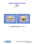
FGRplus and HTplus User Manual
Version
5.0
LUM0009AC Rev A
Covering Firmware v. 2.20
1
FreeWave Technologies, 1880 S. Flatiron Ct., Boulder, CO 80301
Phone: (303) 381-9200, Fax: (303) 786-9948, www.freewave.com
LUM0009AC v.5.0 Rev A
FGRplus and HTplus User Manual
SPREAD SPECTRUM WIRELESS DATA TRANSCEIVER USER MANUAL
Copyright © 1995-2010 by FreeWave Technologies, Inc. All rights reserved. Published 2010.
WARRANTY
FreeWave Technologies warrants your FreeWave® Wireless Data Transceiver against defects
in materials and manufacturing for a period of two years from the date of purchase. In the event
of a Product failure due to materials or workmanship, FreeWave will, at its discretion, repair or
replace the Product.
In no event will FreeWave Technologies Inc., its suppliers, and its licensors be liable for any
damages arising from the use of or inability to use this Product. This includes business interruption, loss of business information, or other loss which may arise from the use of this Product. Please be advised that OEM customer’s warranty periods may vary.
Warranty Policy may not apply:
1. If Product repair, adjustments or parts replacements is required due to accident, neglect, unusual physical, electrical or electromagnetic stress.
2. If Product is used outside of FreeWave specifications.
3. If Product has been modified, repaired or altered by Customer unless FreeWave specifically
authorized such alterations in each instance in writing. This includes the addition of conformal
coating.
The Warranty period begins from the date of shipment and is defined per the Standard Warranty
Policy stated above.
Special Rate Replacement Option:
A special rate replacement option is offered to non-warranty returns or upgrades. The option to
purchase the replacement unit at this special rate is only valid for that RMA, (Return Material
Authorization). The special replacement rate option expires if not exercised within 30 days of
final disposition of RMA.
RESTRICTED RIGHTS
Microsoft® and Windows® are registered trademarks of the Microsoft Corporation. pcANYWHERE® is a registered trademark of Symantec Corporation. Other product names mentioned
in this manual may be copyrights, trademarks, or registered trademarks of their respective companies and are hereby acknowledged.
Information in this document is subject to change without notice. The information contained in
this document is proprietary and confidential to FreeWave Technologies, Inc.
This manual is for use by purchasers and other authorized users of the FreeWave Spread Spectrum Wireless Data Transceiver only.
No part of this document may be reproduced or transmitted in any form or by any means, electronic or mechanical, or for any purpose without the express written permission of FreeWave
Technologies, Inc.
FreeWave’s Spread Spectrum Wireless Data Transceivers are made in the United States of
America.
Printed in the United States of America.
2
FreeWave Technologies, 1880 S. Flatiron Ct., Boulder, CO 80301
Phone: (303) 381-9200, Fax: (303) 786-9948, www.freewave.com
LUM0009AC v.5.0 Rev A
FGRplus and HTplus User Manual
This product is licensed by The United States. Diversion contrary to U.S. law is prohibited. Shipment or re-export of this product outside of The United States may require authorization by the U.S. Bureau of Export Administration. Please contact FreeWave Technologies for assistance and further information.
FCC NOTIFICATIONS
This device complies with part 15 of the FCC rules. Operation is subject to the following two
conditions: 1) This device may not cause harmful interference and 2) this device must accept
any interference received, including interference that may cause undesired operation. This device must be operated as supplied by FreeWave Technologies, Inc. Any changes or modifications made to the device without the express written approval of FreeWave Technologies may
void the user's authority to operate the device.
CAUTION: The model number FGRplusRE has a maximum transmitted output power of
955mW. The model number HTP-900RE has a maximum transmitted output
power of 870mW. It is recommended that the transmit antenna be kept at least 23
cm away from nearby persons to satisfy FCC RF exposure requirements.
This equipment has been tested and found to comply with the limits for a Class B digital device,
pursuant to part 15 of the FCC Rules. These limits are designed to provide reasonable protection against harmful interference in a residential installation. This equipment generates, uses,
and can radiate radio frequency energy and, if not installed and used in accordance with the instructions, may cause harmful interference to radio communications. However, there is no guarantee that interference will not occur in a particular installation. If this equipment does cause
harmful interference to radio or television reception, which can be determined by turning the
equipment off and on, the user is encouraged to try to correct the interference by one or more of
the following measures:
!" Reorient or relocate the receiving antenna.
!" Increase the separation between the equipment and receiver.
!" Connect the equipment into an outlet on a circuit different from that to which the receiver is
connected.
!" Consult the dealer or an experienced radio/TV technician for help.
Note: Whenever any FreeWave Technologies module is placed inside an enclosure a label
must be placed on the outside of that enclosure which includes the module's FCC ID.
UL Notification
Model #HTP-900RE:
“This equipment is suitable for use in Class I, Division 2, Groups A, B, C, and D or nonhazardous locations only.”
“Warning—Explosion Hazard—Substitution of components may impair suitability for Class I,
Division 2.”
The diagnostics port and cable do not have a latching connector and cannot be used in a hazardous location.
3
FreeWave Technologies, 1880 S. Flatiron Ct., Boulder, CO 80301
Phone: (303) 381-9200, Fax: (303) 786-9948, www.freewave.com
LUM0009AC v.5.0 Rev A
FGRplus and HTplus User Manual
Model #FGRplusRE:
“This equipment is suitable for use in Class I, Division 2, Groups A, B, C, and D or nonhazardous locations only.”
“Warning—Explosion Hazard—Substitution of components may impair suitability for Class I,
Division 2.”
The diagnostics port and cable do not have a latching connector and cannot be used in a hazardous location.
Some of the software in the firmware is licensed under the GNU General Public License and
other Open Source and Free Software licenses. You can obtain corresponding source by contacting FreeWave and requesting the source on CD.
IMPORTANT NOTICE
Although both the HTP-900RE and the FGRplusRE radios are outlined
in this manual, they cannot link with each other over the air.
An HTplus can interface with an FGRplus through a hard-wired
Ethernet or serial connection ONLY. For a serial-to-serial connection
between an HTplus and an FGRplus, or between any Plus radio and a
FreeWave serial radio, a Null Modem adapter and a M-to-M Gender
Changer must be used. For an Ethernet-to-Ethernet connection, a
straight-through Ethernet cable may be used, as the port on the Plus radios are auto-crossover ports.
The HTplus radios and the FGRplus radios will not link with each
other, nor will they pass data to each other via RF.
4
FreeWave Technologies, 1880 S. Flatiron Ct., Boulder, CO 80301
Phone: (303) 381-9200, Fax: (303) 786-9948, www.freewave.com
LUM0009AC v.5.0 Rev A
FGRplus and HTplus User Manual
Table of Contents
Choosing Point-to-Point or Point-to-Multipoint Operation.............................................. 10
FreeWave Basic IP Setup via the Serial Port.................................................................... 11
Resetting Radio to Default Settings...................................................................... 16
Accessing Setup via the Built-in Web Server................................................................... 17
Navigating the Plus Interface............................................................................................ 18
Status..................................................................................................................... 19
Hardware Information............................................................................... 19
Firmware Version ..................................................................................... 19
Wireless Version....................................................................................... 19
Software Boot Version & Hardware Version ........................................... 20
Uptime....................................................................................................... 20
Connected To ............................................................................................ 20
Signal ........................................................................................................ 20
Noise ......................................................................................................... 20
Upstream Signal........................................................................................ 20
Upstream Noise......................................................................................... 20
Voltage...................................................................................................... 21
RX Success Rate ....................................................................................... 21
TX Success Rate ....................................................................................... 21
Reflected Power ........................................................................................ 21
Disconnect Count...................................................................................... 21
Temperature .............................................................................................. 21
Distance..................................................................................................... 21
Received.................................................................................................... 22
Packets Sent .............................................................................................. 22
Packets Dropped ....................................................................................... 22
Bad Packets............................................................................................... 22
Un-Acked Packets..................................................................................... 22
Broadcast Packets ..................................................................................... 23
Radio Addressed Packets.......................................................................... 23
Peer to Peer Packets .................................................................................. 23
Radios Parse Error .................................................................................... 23
RX Throughput ......................................................................................... 23
TX Throughput ......................................................................................... 23
Reset Button.............................................................................................. 23
Site Name/Site Contact/System Name/Notes ........................................... 23
Auto Refresh Page .................................................................................... 23
IP Setup................................................................................................................. 24
5
FreeWave Technologies, 1880 S. Flatiron Ct., Boulder, CO 80301
Phone: (303) 381-9200, Fax: (303) 786-9948, www.freewave.com
LUM0009AC v.5.0 Rev A
FGRplus and HTplus User Manual
LAN Network Interface Configuration (Management) ............................ 24
IP Address/Subnet Mask/Default Gateway .................................. 24
Web Page Port............................................................................... 25
Spanning Tree ............................................................................... 25
VLAN Configuration (Data)..................................................................... 25
Mode ............................................................................................. 25
IP Address..................................................................................... 25
Subnet Mask.................................................................................. 25
Default Gateway ........................................................................... 26
Management VLAN ID ................................................................ 26
Data VLAN ID.............................................................................. 26
Save/Apply Button.................................................................................... 26
Serial Setup 1 and Serial Setup 2.......................................................................... 27
Port 1/Port 2 Terminal Server Configuration............................................ 27
Mode ............................................................................................. 27
Disable .............................................................................. 27
TCP Server........................................................................ 28
TCP Client ........................................................................ 28
UDP................................................................................... 28
Multicast ........................................................................... 28
TCP Server Settings.................................................................................. 28
Port................................................................................................ 28
Alarm ............................................................................................ 28
Alarm IP & Port ............................................................................ 29
Maintain/Drop Link ..................................................................... 29
Alarm Retry Limit (Attempts) ...................................................... 29
Inactivity Timeout (Seconds)........................................................ 29
TCP Client Settings................................................................................... 29
IP Address & Port ......................................................................... 29
UDP Settings............................................................................................. 29
Local IP Port ................................................................................. 29
Power Up Dest. IP & Port............................................................. 30
Multicast Settings...................................................................................... 30
Multicast Address & Port.............................................................. 30
Serial Settings ........................................................................................... 30
Baud Rate...................................................................................... 30
Data Bits........................................................................................ 30
Parity ............................................................................................. 31
Stop Bits........................................................................................ 31
Flow Control ................................................................................. 31
CD Mode....................................................................................... 31
Interface ........................................................................................ 31
Modbus RTU ................................................................................ 31
Save/Apply Button.................................................................................... 31
Serial Port Status....................................................................................... 32
6
FreeWave Technologies, 1880 S. Flatiron Ct., Boulder, CO 80301
Phone: (303) 381-9200, Fax: (303) 786-9948, www.freewave.com
LUM0009AC v.5.0 Rev A
FGRplus and HTplus User Manual
Radio Setup........................................................................................................... 33
Operation Mode ........................................................................................ 34
Network Type / Modem Mode ..................................................... 34
Transmission Characteristics .................................................................... 35
Frequency Key .............................................................................. 35
Zones............................................................................................. 35
Max Packet Size............................................................................ 36
Min Packet Size ............................................................................ 36
Transmit Power............................................................................. 39
Retry Timeout ............................................................................... 39
RF Data Rate................................................................................. 40
Point-to-Point Parameters ......................................................................... 40
Transmit Rate................................................................................ 40
Call Book ...................................................................................... 41
Programming Point-to-Point Extended Call Book ........... 42
Programming Point-to-Multipoint Call Book................... 43
Programming Point-to-Multipoint Extended Call Book... 44
Save/Apply Button.................................................................................... 44
Multipoint Networks................................................................................. 45
Multipoint Parameters............................................................................... 45
Addressed Repeat.......................................................................... 45
Broadcast Repeat .......................................................................... 45
...in Multipoint Networks with Repeaters......................... 46
Slave Connect Odds...................................................................... 46
Master Tx Beacon ......................................................................... 46
Network ID ................................................................................... 47
Repeaters....................................................................................... 47
Subnet ID (RX) / Subnet ID (TX)................................................. 47
Save/Apply Button.................................................................................... 50
Overlapping Multipoint Networks............................................................ 50
Security ................................................................................................................. 51
RADIUS Authentication Configuration ................................................... 51
Enable RADIUS............................................................................ 51
RADIUS IP Address ..................................................................... 52
RADIUS Port Number.................................................................. 52
Shared Secret ................................................................................ 52
User-Password .............................................................................. 52
AES Encryption ........................................................................................ 52
Key................................................................................................ 52
MAC Filter................................................................................................ 53
MAC Filter.................................................................................... 53
Detach Local Eth........................................................................... 53
Force SSL (https) .......................................................................... 53
Peer to Peer ................................................................................... 53
7
FreeWave Technologies, 1880 S. Flatiron Ct., Boulder, CO 80301
Phone: (303) 381-9200, Fax: (303) 786-9948, www.freewave.com
LUM0009AC v.5.0 Rev A
FGRplus and HTplus User Manual
Save/Apply Button.................................................................................... 53
SNMP.................................................................................................................... 54
SNMP Agent Configuration ..................................................................... 54
SNMP Version .............................................................................. 54
Read Community .......................................................................... 55
Write Community ......................................................................... 55
Authentication Password (v3)....................................................... 55
Privacy Password (v3) .................................................................. 55
SNMP Trap Configuration........................................................................ 55
Trap Version ................................................................................. 55
Trap Community........................................................................... 55
Min Fault Time (Seconds) ............................................................ 55
Trap Manager 1 IP & Trap Manager 2 IP..................................... 55
SNMP Trap Limits.................................................................................... 56
Voltage.......................................................................................... 56
Rx % Rate ..................................................................................... 56
Tx % Rate ..................................................................................... 56
Reflected Power ............................................................................ 56
S-N Delta ...................................................................................... 56
Signal ............................................................................................ 56
Noise ............................................................................................. 56
Save/Apply Button.................................................................................... 57
SNMP Object Tree.................................................................................... 58
SNMP Object List..................................................................................... 60
RMS ...................................................................................................................... 66
Diagnostics............................................................................................................ 67
Tools ..................................................................................................................... 68
Change Site Information ........................................................................... 68
Site Name...................................................................................... 68
Site Contact................................................................................... 68
System Name ................................................................................ 68
Notes ............................................................................................. 69
Change Password (Alpha-Numeric) ......................................................... 69
TFTP Firmware Upgrade.......................................................................... 69
Address of TFTP Server ............................................................... 69
File Name...................................................................................... 69
Upgrade Firmware Button ............................................................ 69
Global Firmware Upgrade Button ................................................ 69
Operation LEDs ................................................................................................................ 71
Boot-up Sequence ................................................................................................. 71
COM LEDs ........................................................................................................... 71
8
FreeWave Technologies, 1880 S. Flatiron Ct., Boulder, CO 80301
Phone: (303) 381-9200, Fax: (303) 786-9948, www.freewave.com
LUM0009AC v.5.0 Rev A
FGRplus and HTplus User Manual
Error LEDs............................................................................................................ 72
Ethernet Port Lights .............................................................................................. 72
Authentication-Related LEDs ............................................................................... 72
Point-to-Multipoint Operation LEDs.................................................................... 73
Point-to-Point Operation LEDs............................................................................. 73
Choosing a Location for the Transceiver.......................................................................... 74
Factory Default Settings ................................................................................................... 75
Examples of Data Communications Links ....................................................................... 77
Operational RS-422 and RS-485 Information .................................................................. 80
RS-232, RS-422, and RS-485 Pin-outs............................................................................. 81
RS-232 Pin Assignments .................................................................................................. 81
Technical Specifications—HTP-900RE ........................................................................... 82
Technical Specifications—FGRplusRE............................................................................ 84
FreeWave Technical Support............................................................................................ 86
Appendix A (Errata) ......................................................................................................... 87
Appendix B (FreeWave TFTP Users Manual) ................................................................. 88
Appendix C (Changing the IP Address in Windows XP)................................................. 92
Appendix D (FreeWave Discovery Server) ...................................................................... 93
9
FreeWave Technologies, 1880 S. Flatiron Ct., Boulder, CO 80301
Phone: (303) 381-9200, Fax: (303) 786-9948, www.freewave.com
LUM0009AC v.5.0 Rev A
FGRplus and HTplus User Manual
Choosing Point-to-Point or Point-to-Multipoint Operation
A Point-to-Point network is limited to one Gateway and one Endpoint transceiver. Up to 4 Repeaters may be added to extend the reach of the network, but no other Gateway or Endpoint
may be added.
In a Point-to-Multipoint network (also referred to as a Multipoint network) the transceiver, designated as a Gateway, is able to simultaneously communicate with numerous Endpoints. In its
simplest form, a Multipoint network functions with the Gateway broadcasting its messages to
all Endpoints and the Endpoints responding to the Gateway when given data by the device connected to the data port.
It is important to note the differences between Point-to-Point and Multipoint networks. In a
Point-to-Point network all packets are acknowledged, whether sent from the Gateway to the
Endpoint or from the Endpoint to the Gateway. In a Multipoint network, outbound packets from
the Gateway or Repeater to Endpoint or other Repeaters are sent a set number of times determined by the user. The receiving transceiver, Endpoint or Repeater, will accept the first packet
received that passes the 32 bit CRC. However, the packet is not acknowledged. On the return
trip to the Gateway, all packets sent are acknowledged or retransmitted until they are acknowledged. Therefore, the return link in a Multipoint network is generally very robust.
Traditionally, a Multipoint network is used in applications where data is collected from many
instruments and reported back to one central site. As such, the architecture of such a network is
different from Point-to-Point applications. The number of radios in a Multipoint network is influenced by the following parameters:
!" Size of the blocks of data. The longer the data blocks, the smaller the network capacity.
!" Baud rate.
!" The amount of contention between Endpoints. Polled Endpoints vs. timed Endpoints.
!" Use of Repeaters. Using the Repeater setting in a Point-to-Point or a Point-to-Multipoint
network will decrease overall network capacity by at least 50%.
For example, if the network will be polling Endpoints once a day to retrieve sparse data, several
hundred Endpoints could be configured to a single Gateway. However, if each Endpoint will be
transmitting data at greater levels, then fewer Endpoints should be linked to the Gateway. The
overall network will be closer to capacity with fewer Endpoints.
For examples and additional information on data communication links, see the section Examples of Data Communication Links on page 76.
10
FreeWave Technologies, 1880 S. Flatiron Ct., Boulder, CO 80301
Phone: (303) 381-9200, Fax: (303) 786-9948, www.freewave.com
LUM0009AC v.5.0 Rev A
FGRplus and HTplus User Manual
FreeWave Basic Setup via the Serial Port:
This section describes how to either set or determine the IP address of the Plus radio.
To determine or set the IP address of a Plus radio, plug a serial cable into COM 1 (the left
port), with the radio disconnected from the power. Then, follow the instructions below to open
and setup HyperTerminal.
Accessing HyperTerminal’s Setup Menu
Note: The following screen shots are taken from a computer using Windows XP. The display
may vary slightly if using different operating systems.
Click on the Start button. A cascading menu appears. Select Programs, Accessories, Communications and then HyperTerminal. A window appears similar to the following:
Double-click on the Hypertrm.exe icon. The following window appears.
11
FreeWave Technologies, 1880 S. Flatiron Ct., Boulder, CO 80301
Phone: (303) 381-9200, Fax: (303) 786-9948, www.freewave.com
LUM0009AC v.5.0 Rev A
FGRplus and HTplus User Manual
In the Name text box, type in a descriptive name. Select an icon from the Icon selection box.
Click on the OK button. The following “Connect To” dialog box appears:
Select the connection type to be used from the Connect using drop-down menu. In most cases
the connection type will be either Direct to Com1 or Direct to Com2.
Click on the OK button. The Properties dialog box appears for the selected connection type.
12
FreeWave Technologies, 1880 S. Flatiron Ct., Boulder, CO 80301
Phone: (303) 381-9200, Fax: (303) 786-9948, www.freewave.com
LUM0009AC v.5.0 Rev A
FGRplus and HTplus User Manual
The following are the port settings which must be set for a proper connection:
Menu Option to Select
Port Setting
Bits per second
Data bits
Parity
19200
8
None
1
None
Stop bits
Flow control
After selecting the appropriate menu items for each setting, click on the OK button. The following HyperTerminal dialog box appears:
Connect power to the radio. After a few seconds, the following screen should appear in the
HyperTerminal window:
13
FreeWave Technologies, 1880 S. Flatiron Ct., Boulder, CO 80301
Phone: (303) 381-9200, Fax: (303) 786-9948, www.freewave.com
LUM0009AC v.5.0 Rev A
FGRplus and HTplus User Manual
Enter a ‘Y’ or a ‘y’ within 5 seconds (even though the text says 2 seconds) to go into the IP
setup of the radio. Any other key will exit, allowing the radio to complete the boot-up. Upon
entering a ‘Y’, a password prompt will appear:
Entering the Administrator password (factory default is ‘admin’) will bring up the FreeWave
Setup Menu:
14
FreeWave Technologies, 1880 S. Flatiron Ct., Boulder, CO 80301
Phone: (303) 381-9200, Fax: (303) 786-9948, www.freewave.com
LUM0009AC v.5.0 Rev A
FGRplus and HTplus User Manual
Choosing option 0 will bring up the IP Setup menu:
From this menu, the various IP Address and VLAN settings can be changed.
!" Option 0 will change the IP Address of the radio. (see p. 24)
!" Option 1 will change the Subnet Mask (also called Netmask) of the radio. (see p. 24)
!" Option 2 will change the Default Gateway of the radio. (see p. 24)
!" Option 3 will change the port number of the radio’s Web-based configuration screens. (see
p. 25)
!" Option 4 will change the VLAN Mode (Disabled, Tagged, Untagged) of the radio. (see p.
25)
!" Option 5 will change the Data VLAN IP Address. (see p. 25)
!" Option 6 will change the Data VLAN Subnet Mask. (see p. 25)
!" Option 7 will change the Data VLAN Default Gateway. (see p. 26)
!" Option 8 will change the Management VLAN ID. (see p. 26)
!" Option 9 will change the Data VLAN ID. (see p. 26)
15
FreeWave Technologies, 1880 S. Flatiron Ct., Boulder, CO 80301
Phone: (303) 381-9200, Fax: (303) 786-9948, www.freewave.com
LUM0009AC v.5.0 Rev A
FGRplus and HTplus User Manual
Selecting option 5 from the main Setup Menu will bring up the Security menu:
From this menu, some of the various security options can be changed.
!" Option 0 clears out the MAC Filter list, setting the radio back to allowing all Ethernet traffic.
Exiting the Setup Menu will initiate a reboot of the radio.
FreeWave Discovery Server
The IP Address of a Plus radio can also be set using the FreeWave Discovery Server. For more
information on the FreeWave Discovery Server, please see Appendix D (see p. 90).
Resetting Radio to Default Settings:
Follow the steps for accessing Basic IP Setup as indicated on pages 11—15. When the Enter
Password: prompt appears, the password ‘default’ can be entered. The radio will then reboot,
and all of the radio settings will be reset to the factory defaults (see p.74).
16
FreeWave Technologies, 1880 S. Flatiron Ct., Boulder, CO 80301
Phone: (303) 381-9200, Fax: (303) 786-9948, www.freewave.com
LUM0009AC v.5.0 Rev A
FGRplus and HTplus User Manual
Accessing Setup via the Built-in Web Server:
This section will discuss how to configure the settings in the Plus radio.
Plug the radio into either a computer or a switch/router using an RJ-45 cable. Open a
web browser (IE, Netscape, Firefox, etc.) and type the IP address of the radio into the address
bar. For example, to access a Plus radio with an IP address of 192.168.111.90, type
“http://192.168.111.90” into the address bar of the web browser. A static IP address on the
same subnet may need to be assigned to the router/switch and/or the computer to access the
radio (see Appendix C, p. 89). The default IP address from the factory is 192.168.111.100.
A prompt for a user name and password will appear. The default username for the Administrator login is ‘admin’, the password is ‘admin’. The default username for the Guest login
is ‘guest’, the password is ‘guest’.
The Administrator login has full permission to change all settings on the radio, including Firmware upgrades. The Guest login can only view the settings. The Guest login can see the Status,
IP Setup, Serial Gateway Setup, and Radio Setup pages. The Guest login cannot save any
changes, cannot see the Security or Maintenance/Tools pages, and cannot reboot the radio.
17
FreeWave Technologies, 1880 S. Flatiron Ct., Boulder, CO 80301
Phone: (303) 381-9200, Fax: (303) 786-9948, www.freewave.com
LUM0009AC v.5.0 Rev A
FGRplus and HTplus User Manual
Navigating the Plus interface
Along the left side of all screens in the Web-based interface of the Plus is the
Pages List. Clicking the items in this list allows navigation to the different
configuration pages available in the Plus. The currently selected page is highlighted in teal.
Below the Pages List is the Reboot button. Clicking this button forces a reboot of the radio.
Pages List
and Reboot
button
When making changes on the various settings in the Plus, it is necessary
to click the Save/Apply button before navigating away from that page
or rebooting the radio. No changes will take effect until the Save/Apply
button is clicked. When the changes have been successfully saved and
applied, the message “Change Succeeded” will appear beneath the Reboot button.
Change Succeeded
message
Save/Apply
button
Some settings changes (such as changes to the IP Setup section)
require a reboot to complete the changes. When such a change is
made, the “Change Succeeded” message changes to include a link
labeled “Reboot Required”. Clicking either the “Reboot Requiured”
link or the Reboot button will reboot the radio and apply the requested changes. If the user does not reboot the radio right away, the
requested changes will not be made until the radio is rebooted.
Reboot required
message
18
FreeWave Technologies, 1880 S. Flatiron Ct., Boulder, CO 80301
Phone: (303) 381-9200, Fax: (303) 786-9948, www.freewave.com
LUM0009AC v.5.0 Rev A
FGRplus and HTplus User Manual
Status:
This page will include all of the device status information. Nothing on this screen is user adjustable. If the Auto Refresh Page box at the bottom of the page is checked, this page updates
every 10 seconds.
Hardware Information
This is displayed at the top of every page in the radio setup. It displays the model name of the
radio, the radio’s IP address, the radio’s MAC (hardware) address, and the radio’s Serial Number.
Firmware Version
This displays the current version number of the firmware revision installed on the radio.
Wireless Version
This displays the current version number of the Radio Frequency module’s firmware.
19
FreeWave Technologies, 1880 S. Flatiron Ct., Boulder, CO 80301
Phone: (303) 381-9200, Fax: (303) 786-9948, www.freewave.com
LUM0009AC v.5.0 Rev A
FGRplus and HTplus User Manual
Software Boot Version & Hardware Version
These settings are for internal FreeWave use. When speaking with a Technical Support representative, they may ask for this information.
Uptime
This is the total time the radio has been running since the last reboot.
RF Stats
Connected To
This field will display the serial number of the radio’s upstream connection (i.e. the Gateway or
a Repeater). This statistic will display a ‘0’ in a Multipoint Gateway.
Signal
The Signal field indicates the level of received signal at this transceiver. The signal source is the
transceiver that transmits to this transceiver (shown in the Connected To field). The number is
an average of the received signal levels measured at each frequency in the transceiver's frequency hop table. For a reliable link, the margin between the average signal level and average
noise level should be 30dBm or more. Low average signal levels can often be corrected with
higher gain antennas, better antenna placement and/or additional Repeaters.
Note: Please consult the install manual for antenna and FCC requirements.
Noise
The Noise field indicates the level of background noise and interference at this transceiver. The
number is an average of the noise levels measured at each frequency in the transceiver’s frequency hop table. Ideally, noise levels should be below –80dBm and the difference between the
average signal level and average noise level should be 30dBm or more. Noise levels significantly higher than this are an indication of a high level of interference that may degrade the performance of the link. High noise levels can often be mitigated with band pass filters, antenna
placement or antenna polarization.
Upstream Signal
The Upstream Signal field indicates the level of the signal received by the upstream radio
(listed in the Connected To field) from this transceiver. The number is an average of the received signal levels measured at each frequency in the upstream radio’s frequency hop table.
This statistic is only valid in a Multipoint Endpoint or Multipoint Repeater.
Upstream Noise
The Upstream Noise field indicates the level of the RF noise at the upstream radio (listed in the
Connected To field). The number is an average of the noise levels measured at each frequency
in the upstream radio’s frequency hop table. Ideally, noise levels should be below –80dBm and
20
FreeWave Technologies, 1880 S. Flatiron Ct., Boulder, CO 80301
Phone: (303) 381-9200, Fax: (303) 786-9948, www.freewave.com
LUM0009AC v.5.0 Rev A
FGRplus and HTplus User Manual
the difference between the average signal level and average noise level should be 30dBm or
more. This statistic is only valid in a Multipoint Endpoint or Multipoint Repeater.
Voltage
This displays the voltage level of the power being supplied to the radio.
RX Success Rate
This statistic shows the percentage of packets successfully received by this radio. This statistic
will show ‘0.00%’ in a Multipoint Gateway. This statistic is only valid in a Multipoint network.
FreeWave recommends a minimum of 75% for proper radio operation.
TX Success Rate
This statistic shows the percentage of packets sent by the radio that successfully reached the
upstream radio (i.e. the Gateway or a Repeater). This statistic will show ‘0.00%’ on a Multipoint Gateway or Multipoint Repeater. This statistic is only valid on Multipoint Endpoint radios. FreeWave recommends a minimum of 75% for proper radio operation.
Reflected Power
This is a measurement of the transmitted power that is reflected back into the transceiver from
mismatched antennas, mismatched cables, or loose connections between the transceiver and the
antenna. A reading of 0-5 is good. 5-29 is acceptable to marginal. 30+ is unacceptable and
indicates that the connections should be inspected for loose connections and cable quality.
Disconnect Count
This statistic show the number of times the radio has lost its RF connection to its upstream radio. This statistic is not valid in Multipoint Gateways or Point-to-Point Repeaters.
Temperature
This indicates the current operating temperature of the radio in both degrees Celsius and degrees Fahrenheit.
Distance
This is the distance between this radio and the radio to which it is directly linked. Distances
greater than 3/5 of a mile are typically accurate to within 100 feet. Shorter distances are not
reported accurately.
21
FreeWave Technologies, 1880 S. Flatiron Ct., Boulder, CO 80301
Phone: (303) 381-9200, Fax: (303) 786-9948, www.freewave.com
LUM0009AC v.5.0 Rev A
FGRplus and HTplus User Manual
Packet Stats
Received
This statistic shows the number of Ethernet packets and bytes of data the radio has received
over its radio link.
Packets Sent
This statistic shows the number of Ethernet packets and bytes of data the radio has sent over its
radio link.
Packets Dropped
This statistic shows the number of Ethernet packets the radio has thrown away due to its data
buffer being full.
Bad Packets
This statistic shows the number of Ethernet packets the radio has thrown away due to a bad
CRC checksum.
Un-Acked Packets
This statistic shows the number of Ethernet packets sent using a broadcast MAC address. These
packets are unacknowledged by the destination device.
In a radio network where the Repeaters setting (see p. 46) is set to Enabled, all packets become Un-Acked, and this statistic displays a high number of packets.
In a radio network where the Repeaters setting is set to Disabled, this statistic can indicate the
following:
!" On the Gateway, this statistic shows a packet that is addressed to a device the Gateway believes is on its wireless network, the Gateway has exhausted all of its packet retries, and the
Gateway never received any acknowledgements for that packet. Reasons for this are: the
destination address is not actually in the wireless network, the destinations could not hear
the packet from the Gateway, or the Gateway could not hear the acknowledgement from the
destination.
!" On an Endpoint, this statistic shows a packet that is being sent to the Gateway, the Endpoint
has received no acknowledgements from the Gateway, and the Endpoint has exhausted its
maximum number of attempts per the Slave Connect Odds setting (see p. 45).
It is still possible that any packet counted by this statistic was successfully delivered, but the
radio is unable to obtain an acknowledgement that the packet succeeded.
22
FreeWave Technologies, 1880 S. Flatiron Ct., Boulder, CO 80301
Phone: (303) 381-9200, Fax: (303) 786-9948, www.freewave.com
LUM0009AC v.5.0 Rev A
FGRplus and HTplus User Manual
Broadcast Packets
This statistic shows the number of packets sent over the radio where the broadcast address was
the packet destination.
Radio Addressed Packets
This statistic shows the number of packets sent over the radio where another radio in the wireless network was the packet destination.
Peer to Peer Packets
This statistic is only valid in a Multipoint Gateway. This statistic reflects the number of packets
received by the Gateway from the radio link and re-transmitted out, as the destination address
was determined to be across the radio link.
Radio Parse Error
This statistic displays the number or errors in data transmission between the Ethernet stack and
the radio interface.
RX Throughput
This statistic shows the throughput of data being received over the radio link within the last 1
second.
TX Throughput
This statistic shows the throughput of data being transmitted over the radio link within the last 1
second.
Reset Button
Clicking this button will reset all of the statistics in the Packet Stats section to 0. Powercycling or rebooting the radio will also reset all the statistics.
Site Information
Site Name / Site Contact / System Name / Notes
These are user-defined fields. The values for these fields can be entered under the Tools page.
Auto Refresh Page
Checking this box causes the Status page to refresh its information every 10 seconds. By default, this box is not checked and the Status page does not refresh. Navigating away from the
Status page will cause this box to revert to its unchecked default.
23
FreeWave Technologies, 1880 S. Flatiron Ct., Boulder, CO 80301
Phone: (303) 381-9200, Fax: (303) 786-9948, www.freewave.com
LUM0009AC v.5.0 Rev A
FGRplus and HTplus User Manual
IP Setup:
This page will be used to setup the IP address, Subnet Mask, and Default Gateway of the radio.
Please check with a Network Administrator before adjusting these settings. Many of these settings are also available through Basic IP Setup (see p. 11) or the Discovery Server (see p. 90).
LAN Network Interface Configuration (Management)
IP Address / Subnet Mask / Default Gateway
A unique IP address will need to be assigned to each Plus radio modem. The IP addresses must
be in the proper subnet. A Network Administrator will be able to assign the proper IP addresses
for the radios. It is also possible to have a transparent bridge with an IP address of
255.255.255.255, but serial port functionality, the Security features, and access to the Webbased setup pages will be lost. To reassign a valid IP address, follow the instructions in Basic
IP Setup (see p. 11) or use the FreeWave Discovery Server (see p. 90). The Subnet Mask and
Default Gateway are normally assigned by a network administrator. NOTE: Putting multiple
devices on the network with the same IP address can cause the whole network to crash.
When the VLAN Mode option (see p. 25) is set to Tagged or Untagged, this IP information
will be assigned to the Management portion of the radio (Setup pages, SNMP, Discovery
Server). Any communication with the Plus’s Setup pages, SNMP, or changes via the Discovery
Server will need to be addressed to this IP address and tagged with the Management VLAN
ID.
24
FreeWave Technologies, 1880 S. Flatiron Ct., Boulder, CO 80301
Phone: (303) 381-9200, Fax: (303) 786-9948, www.freewave.com
LUM0009AC v.5.0 Rev A
FGRplus and HTplus User Manual
Web Page Port
This setting allows the assigned port for the Web interface Setup pages to be changed. The default setting is port 80, the standard Web page port. If this setting is changed from port 80, the
proper port number must be included when accessing the Setup pages:
http://<IP address>:<Port>, where <IP address> is the IP address of the Plus radio, and
<Port> is the port number assigned in the IP Setup page. Any valid TCP port can be entered
from 1 to 65535. If an invalid TCP port is entered, the Plus radio will default the Web Page Port
setting to 80. In the example below, the Web Page port was changed to 5150.
Example:
Spanning Tree
Checking the Enable box will cause a Gateway radio to utilize Spanning Tree Protocol (IEEE
802.1D). This will eliminate the possibility of the radios creating a network loop, which can
cause network-wide problems. Spanning Tree Protocol does use radio bandwidth, as any Spanning Tree radios are constantly communicating their network “location.” FreeWave Technologies recommends leaving Spanning Tree unchecked, unless Spanning Tree Protocol is required
by your application.
VLAN Configuration (Data)
Mode
This drop-down selects whether VLAN will be active and which mode will be utilized.
!" Disabled: VLAN will not be used.
!" Tagged: If the data coming into the radio’s local Ethernet port is tagged with a
VLAN ID, select this option. The radio will bridge the data, leaving the VLAN ID
as-is.
!" Untagged: If the data coming into the radio’s local Ethernet port is not tagged with
a VLAN ID, select this option. The radio will accept the data, tag it with the VLAN
ID entered in the Data VLAN ID field, and send it across the radio link. Data arriving at this radio and being sent out of the local Ethernet port will have any VLAN
tag removed before being sent out of the port
IP Address
When the VLAN Mode is set to Tagged or Untagged, the IP Address entered here will be assigned to the Data portion of the radio (Ethernet port traffic and terminal server communication). Any data destined for one of the Plus’s serial ports or its Ethernet port will need to be addressed to this IP address and tagged with the Data VLAN ID.
Subnet Mask
The appropriate subnet mask for the Data VLAN IP address (above) should be entered in this
box.
25
FreeWave Technologies, 1880 S. Flatiron Ct., Boulder, CO 80301
Phone: (303) 381-9200, Fax: (303) 786-9948, www.freewave.com
LUM0009AC v.5.0 Rev A
FGRplus and HTplus User Manual
Default Gateway
The appropriate default gateway for the Data VLAN IP address (p. 25) should be entered in this
box.
Management VLAN ID
Computers and devices using the VLAN ID entered here will be able to access the radio’s Setup
Pages, receive SNMP information, send SNMP commands, and view the radio via the FreeWave Discovery Server.
Data VLAN ID
Data using this VLAN ID will be allowed to come into or be sent out of the radio’s local
Ethernet port and will be allowed to access the serial ports via the terminal server.
**NOTE** Not every network needs or uses VLAN IDs. The Mode setting is normally kept at
Disabled. Changes to these settings should be approved by a Network Administrator.
Save/Apply Button
Clicking this button saves any settings changes in the IP Setup page, and applies those changes
to the radio. Before the changes become active, the radio requires a reboot. Navigating away
from the IP Setup page without clicking this button discards any changes.
26
FreeWave Technologies, 1880 S. Flatiron Ct., Boulder, CO 80301
Phone: (303) 381-9200, Fax: (303) 786-9948, www.freewave.com
LUM0009AC v.5.0 Rev A
FGRplus and HTplus User Manual
Serial Setup 1 and Serial Setup 2:
This is where the port numbers and data settings for each serial port can be assigned. These settings need to match the device to which each port is connected. The ports are independent of
each other: they can have different baud rates, parity, protocol, etc. To access either port, a client will need to call the IP address of the radio plus the port number. If both ports are disabled,
the Basic IP Setup will still work through Port 1. Each serial port is configured on its own page.
Port 1/Port 2 Terminal Server Configuration
Mode
This drop-down box selects the operating mode of the radio’s terminal server. The available
modes are described below.
Disabled
Selecting this mode disables the associated serial port, preventing it from accepting data
or a TCP connection.
TCP Server
Selecting this mode enables the radio as a TCP terminal server (its default mode). The
number entered in the Port box in the TCP Server Settings section will be the TCP
port that the radio listens to for connection requests. In the picture above, the server is
set for port 7000.
27
FreeWave Technologies, 1880 S. Flatiron Ct., Boulder, CO 80301
Phone: (303) 381-9200, Fax: (303) 786-9948, www.freewave.com
LUM0009AC v.5.0 Rev A
FGRplus and HTplus User Manual
TCP Client
Selecting this mode causes the radio to act as a TCP client to the IP address and port number
entered in the TCP Client Settings section. Upon booting up, the radio will create a persistent
outgoing TCP connection to the entered IP address and port number. Any data sent to the associated serial port on the radio is automatically directed to the entered IP address and port number.
UDP
Selecting this mode enables the radio as a UDP terminal server using the port number entered in
the UDP Settings section. The port number entered in the UDP Settings section will be the
UDP port that the radio listens to for requests. Once a request comes into that port, the radio
will send any incoming serial data to the IP address of the requesting device. The radio will
continue doing so until a new device makes a request on that UDP port. The radio will always
send the serial data to the address of the last successful requesting device.
Multicast
Selecting this mode will
allow a one-to-many connection from the Multipoint Gateway’s serial
port to the interested Multipoint Repeaters’ and/or
Endpoints’ serial ports.
In a Multipoint Gateway
radio, selecting this mode
will cause the radio to act
as an IP Multicast Sender on the Multicast address and port entered in the Multicast Settings
section.
In a Multipoint Repeater or Multipoint Endpoint, selecting this mode will register that radio’s
interest for any Multicast packets sent from the Multicast address and port entered in the Multicast Settings section.
TCP Server Settings
Port
The number entered in this box will be the TCP port the radio listens to for incoming TCP connections. Any valid TCP port number (0—65535) may be entered in this box.
Alarm
Checking the Enable Alarm box enables the port as an alarm client. To use this function, the
Alarm IP & Port boxes must also be configured. The radio will act as a terminal server on the
28
FreeWave Technologies, 1880 S. Flatiron Ct., Boulder, CO 80301
Phone: (303) 381-9200, Fax: (303) 786-9948, www.freewave.com
LUM0009AC v.5.0 Rev A
FGRplus and HTplus User Manual
port specified in the Port box (see also: Port, p. 28). If there is no current TCP connection to
this port and serial data is received on the local serial port, the radio will become a client and
make a connection to the IP address and port number specified in the Alarm IP & Port line.
Alarm IP & Port
This line sets the IP address and TCP port number the radio will connect to when it becomes a
client per the Alarm setting (above). The IP address is entered in the box to the left of the colon. The TCP port number is entered in the box to the right of the colon. The port number must
be set to a valid TCP port (0—65535).
Maintain/Drop Link
Checking the Drop Link checkbox will cause the outgoing connection to the Alarm IP & Port
to be dropped as soon as the serial data is sent. Unchecking the Drop Link checkbox will keep
the connection to the remote IP Address and port number active until the radio is rebooted or
the server side drops the link.
Alarm Retry Limit (Attempts)
This setting is the number of times the radio will attempt to create an outgoing TCP connection
when acting as an alarm client (see Alarm, above). When the radio reaches the number of retries listed in this setting without a successful connection, it will cease trying and act as if no
alarm was received. The incoming data will be flushed from the radio’s data buffer. If new incoming data is received, the radio will attempt to connect again. A setting of “0” means that the
radio will continuously try to connect to the alarm server until the radio is rebooted.
Inactivity Timeout (Seconds)
This setting controls how long an incoming TCP connection must be idle (i.e. no data being
transferred) before the radio drops the connection. This setting is in seconds. A setting of “0”
means that the radio will never disconnect an idle connection—all disconnects will need to
come from the client.
TCP Client Settings
IP Address & Port
This line sets the IP address and TCP port number the radio will create a connection to upon
boot-up, when the radio is set to the TCP Client mode (see TCP Client, p. 28). The IP address
is entered in the box to the left of the colon. The TCP port number is entered in the box to the
right of the colon. The port number must be set to a valid TCP port (0—65535).
UDP Settings
Local IP Port
The port number entered in this box is the UDP port the radio will listen to for connections
29
FreeWave Technologies, 1880 S. Flatiron Ct., Boulder, CO 80301
Phone: (303) 381-9200, Fax: (303) 786-9948, www.freewave.com
LUM0009AC v.5.0 Rev A
FGRplus and HTplus User Manual
when the Mode is set to UDP. The port number must be set to a valid UDP port (0—65535).
Power Up Dest. IP & Port
In this line, an IP Address and Port Number can be entered. In a radio set to a Mode of UDP,
Before an incoming UDP request has been received by the radio, the IP Address and Port number entered here will be where the radio sends any serial data coming into its serial port. Once a
UDP request is received, the radio will operate as listed above. The IP address is entered in the
box to the left of the colon. The UDP port number is entered in the box to the right of the colon.
The port number must be set to a valid UDP port (0—65535).
Multicast Settings
Multicast Address & Port
This line sets the IP address and port number that will be used for Multicast. In a Multipoint
Gateway, this will be the sending address. In Multipoint Endpoints and Multipoint Repeaters,
this will be the address they register interest in (see Multicast, p. 28). The IP address is entered
in the box to the left of the colon. The UDP port number is entered in the box to the right of the
colon. The port number must be set to a valid UDP port (0—65535).
Any IP addresses used in this line must be designated Multicast addresses (224.0.0.0 to
239.255.255.255).
Serial Settings
Baud Rate
This setting is the communication rate between the serial port on the radio and the instrument to
which it is connected. It is important to note that this is independent of the baud rate for any
other transceivers in the network. It is also independent of the other serial port on the radio. For
example, a pair of transceivers may be used in an application to send data from remote process
instrumentation to an engineer's computer. In this application, the baud rate for the transceiver
on the instrumentation might be set to 9600, and the transceiver on the engineer’s computer
might be set to 57,600. A serial radio may be attached to one port and an RTU/PLC/End Device attached to the other. In this case, one port might be set at 115,200 and the other might be
set at 9,600. It is usually most desirable to set the baud rate to the highest level supported by the
device to which it is connected. In certain circumstances, however, this may actually result in
slower data communications (i.e.: trying to run higher baud rates [38400 and higher] without
flow control).
Data Bits
This option sets the number of data bits the serial port will send. This should match the number
of data bits the connected device requires or is set to. The available settings are: 5, 6, 7, and 8.
30
FreeWave Technologies, 1880 S. Flatiron Ct., Boulder, CO 80301
Phone: (303) 381-9200, Fax: (303) 786-9948, www.freewave.com
LUM0009AC v.5.0 Rev A
FGRplus and HTplus User Manual
Parity
This option sets the parity type the serial port will use. This should match the parity required by
the connected device’s settings. The available settings are: None, Even, and Odd.
Stop Bits
This option sets the number of stop bits the serial port will send. This should match the number
of stop bits required by the connected device’s settings. The available settings are: 1 and 2.
Flow Control
This option sets whether hardware flow control will be used on this serial port. The available
settings are:
None
Uses software flow control (XON / XOFF)
Hardware
Hardware flow control (RTS / CTS)
CD Mode
This controls the function of the CD line on the serial port.
Normal
CD is asserted when a TCP connection to the associated port is made, and deasserted when the TCP connection is closed. Most serial devices will use this option.
Keyed
CD asserts 500 µs before transmit, and de-asserts 1 ms after the transmission of
the first bit of the last byte of data. This option should be used with serial devices that require
the CD line to be asserted prior to the transmission of data.
Interface
This option sets the serial protocol the serial port will use. This should match the protocol required by the connected device. The available settings are: RS232, RS485, and RS422. See
page 80 for pinout information.
Modbus RTU
This option adjusts for Modbus RTU timing. When enabled, the radio will gather data on the
serial port until there is a break in the data due to Modbus RTU timing (every 256 bytes). The
data is then sent as one TCP packet. This option is recommended for any serial data that consist
of many small packets of data. This option is enabled by default.
Save/Apply Button
Clicking this button saves any settings changes in the Serial Setup 1 or Serial Setup 2 pages,
and applies those changes to the radio. Navigating away from the Serial Setup 1 page or the
Serial Setup 2 page without clicking this button discards any changes.
31
FreeWave Technologies, 1880 S. Flatiron Ct., Boulder, CO 80301
Phone: (303) 381-9200, Fax: (303) 786-9948, www.freewave.com
LUM0009AC v.5.0 Rev A
FGRplus and HTplus User Manual
Serial Port Status
Clicking on the Serial Port Status link at the bottom of this page will open a new window
(shown below) which displays Terminal Server Diagnostics. For each serial port, the current
status of the Terminal Server is listed first (Waiting, Connected, etc.).
The Ethernet line shows the amount of data received (rx) and transmitted (tx) from the terminal server. Received (rx) data indicates data received on the radio from the serial port. Transmitted (tx) data indicates data sent from the radio out the serial port. This amount is in bytes.
The Serial line shows the amount of data received (rx) and transmitted (tx) from the serial port.
Received (rx) data indicates data coming from the connected device into the serial port. Transmitted (tx) data indicates data sent out the serial port to the connected device. This amount is in
bytes.
This page updates every 5 seconds. Clicking the Refresh link will manually refresh the page.
32
FreeWave Technologies, 1880 S. Flatiron Ct., Boulder, CO 80301
Phone: (303) 381-9200, Fax: (303) 786-9948, www.freewave.com
LUM0009AC v.5.0 Rev A
FGRplus and HTplus User Manual
Radio Setup:
This page is where the radio’s Operation Mode, Transmission Characteristics, Multipoint Parameters, and the Call Book can be set up.
When setting the operation mode, there are two menus: Network Type and Modem Mode. The
Network Type is either Point-To-Point or Point-To-Multipoint. The Modem Mode is either
Gateway, Repeater, or Endpoint.
In Point-To-Point mode, the repeater is not an Endpoint/Repeater. The Call Book must also be
used in Point-To-Point mode.
In Point-To-Multipoint mode, either the Call Book or Network ID can be used. Any Repeater
in a Point-To-Multipoint network will be an Endpoint/Repeater.
33
FreeWave Technologies, 1880 S. Flatiron Ct., Boulder, CO 80301
Phone: (303) 381-9200, Fax: (303) 786-9948, www.freewave.com
LUM0009AC v.5.0 Rev A
FGRplus and HTplus User Manual
Operation Mode
Network Type / Modem Mode
The Network Type and Modem Mode options designate the method FreeWave transceivers use
to communicate with each other. FreeWave Plus transceivers operate in a Gateway to Endpoint
configuration. Before the transceivers can operate together, they must be set up to properly
communicate.
In a standard configuration, the Gateway Mode should be used on the end which will be connected to the LAN. When setting up the transceiver, remember that a number of parameters are
controlled by the settings in the Gateway. Therefore, deploying the Gateway on the communications end where it will be easier to access is strongly advised.
Operation
Mode
Point-to-Point &
Gateway
Description
This mode designates the transceiver as the Gateway in Point-to-Point mode. The Gateway
may call any or all Endpoints designated in its Call Book.
A quick method of identifying a Gateway is to power the transceiver. Prior to establishing a
communication link with an Endpoint or Repeater, all three of the Gateway’s lower LEDs
(CD, TX, CTS) will be solid red.
Point-to-Point &
Endpoint
This mode designates the transceiver as an Endpoint in Point-to-Point mode. The Endpoint
communicates with any Gateway in its Call Book—either directly or through up to four Repeaters.
When functioning as an Endpoint, the Entry to Call feature in the transceiver’s Call Book is
not operational.
Multipoint &
Gateway
This mode designates the transceiver as a Gateway in Multipoint mode. This mode allows
one Gateway transceiver to simultaneously be in communication with numerous Endpoints
and Repeaters.
A Multipoint Gateway communicates only with other transceivers designated as Multipoint
Endpoints or Multipoint Repeaters.
Multipoint &
End-Point
This mode designates the transceiver as an Endpoint in Multipoint mode. This mode allows
the Endpoint to communicate with a Multipoint Gateway. The Endpoint may communicate
with its Gateway through one or more Repeaters.
Point-to-Point &
Repeater
FreeWave allows the use of up to four Repeaters in a Point-to-Point communications link,
significantly extending the operating range. When designated as a Point-to-Point Repeater, a
transceiver behaves as a pass-through link. All settings for the call book, baud rates and radio
transmission characteristics are disabled. A Repeater will connect with any Gateway that
calls it. The Repeater must be set up properly in the Gateway's call book. This Network
Type and Modem Mode should be the ones used when operating the Plus as a terminal
server only (no RF connectivity). Adding a repeater to the radio network results in
greatly reduced throughput—over 50% less.
(Single-radio
Repeater)
Multipoint &
Repeater
(Single-radio
Repeater)
This option allows the transceiver to operate as an Endpoint/Repeater in a Multipoint network. Adding a repeater to the radio network results in greatly reduced throughput—
over 50% less. Some advanced features of the Plus radio do not operate in networks
containing Repeaters. FreeWave Technologies does not recommend the use of singleradio Repeaters.
34
FreeWave Technologies, 1880 S. Flatiron Ct., Boulder, CO 80301
Phone: (303) 381-9200, Fax: (303) 786-9948, www.freewave.com
LUM0009AC v.5.0 Rev A
FGRplus and HTplus User Manual
Transmission Characteristics
The Transmission Characteristics section of the Radio Setup page allows the user to modify
several different parameters in the transceiver. Many of these parameters must be maintained
throughout the network for proper functionality.
Note: This section is only for the advanced user who has a good understanding of the principles of radio data transmission.
In a Point-to-Point network, the settings for the Endpoints and Repeaters that are not determined by the Gateway are Transmit Power and Retry Time Out. All other settings in a Pointto-Point network are determined by the Gateway radio’s settings.
Frequency Key
The Frequency Key setting in the Radio Setup menu allows the user to modify the hopping patterns of the transceiver. There are 15 choices available for the Frequency Key setting (0-9 and
A-E), representing 15 different pseudo-random hop patterns. This is to minimize the interference with other FreeWave transceivers operating in the area. For instance, if there were 10 pairs
of FreeWave transceivers operating on different networks in close proximity, setting a different
Frequency Key value for each pair reduces the chance that transceivers will hop to the same
frequency at the same time. If two networks were to hop to the same frequency by chance, the
next hop would be to a different frequency for both networks.
Additional network separation can be gained by adjusting the Max and Min packet sizes.
Zones
The idea of frequency zoning is to divide the available band (902 MHz to 928 MHz) into
smaller bands—in this case 16 smaller bands each consisting of 7 or 8 frequency channels.
These 16 Zones are listed in the Zones line of the Radio Setup page. A checkmark indicates
that zone will be used by the radio. A blank box indicates the radio will not use those frequencies. The zones listed are in MHz. The radio requires at least one zone active to operate. If all
Frequency Zones are de-selected, the radio will operate as if all zones were selected.
Any Endpoint or Endpoint/Repeater radios will take their Frequency Zone settings from the
Gateway radio, regardless of Network Type. Therefore, this section should only be changed on
the Gateway radio.
35
FreeWave Technologies, 1880 S. Flatiron Ct., Boulder, CO 80301
Phone: (303) 381-9200, Fax: (303) 786-9948, www.freewave.com
LUM0009AC v.5.0 Rev A
FGRplus and HTplus User Manual
Max Packet Size & Min Packet Size
The Max and Min Packet Size settings and the RF Data Rate determine the number of bytes in
the packets. Throughput can be enhanced when packet sizes are optimized. In Point-to-Point
mode, the Max and Min Packet Settings will not have material impact on throughput unless
A data rate of 540 Kbps (for the HTplus) or 92 Kbps (for the FGRplus) is desired. However,
this may have an impact on latency. For example, if small amounts of data are sent and large
packet sizes are selected, there would be a certain amount of time “wasted” between each
packet.
The following tables provide the information to determine optimum setting values.
The default settings for Max packet size, Min packet size, and RF Data Rate on the HTP-900RE
are 9, 1, and 867 Kbps, respectively.
The default settings for Max packet size, Min packet size, and RF Data Rate on the FGRPlusRE
are 9, 1, and 154 Kbps, respectively.
The following table defines the Minimum packet size (in bytes) by way of charting the Min
Packet Size setting versus the RF Data Rate setting. Using the default settings, the actual minimum packet size for the radios, in bytes, is 19 in the HTP-900RE and 21 in the FGRPlusRE.
Minimum Packet Size Definition
HTplus/FGRplus
Min Setting
Min Packet Size
(bytes)
RF Data Rate =
867 Kbps
Min Packet Size
(bytes)
RF Data Rate =
154 Kbps
Min Packet Size (bytes)
RF Data Rate =
614 Kbps/115 Kbps
0
14
15
8
1
19
21
12
2
24
26
16
3
29
31
20
4
34
37
24
5
39
42
28
6
44
47
32
7
49
53
36
8
54
58
40
9
59
63
44
36
FreeWave Technologies, 1880 S. Flatiron Ct., Boulder, CO 80301
Phone: (303) 381-9200, Fax: (303) 786-9948, www.freewave.com
LUM0009AC v.5.0 Rev A
FGRplus and HTplus User Manual
The following table defines the Maximum packet size (in bytes) by way of charting the Min
Packet Size setting versus the Max Packet Size setting where the RF Data Rate is set to
154 Kbps. Using the default settings, the actual maximum packet size, in bytes, is 213.
Maximum Packet Size Definition with RF Date Rate of 154 kbps (in bytes)
Max Setting (Blank grey area = Not Recommended)
Min Setting
0
1
2
3
4
0
1
2
3
4
5
6
7
8
9
5
154
159
165
170
6
7
8
9
154
159
165
170
175
181
186
191
165
170
175
181
186
191
197
202
207
213
186
191
197
202
207
213
218
223
229
234
207
213
218
223
229
234
239
245
250
255
Referencing the default settings, the Gateway will transmit up to 213 bytes on every hop. If fewer than
213 bytes are transmitted by the Gateway, the balance is allocated to the Endpoint's transmission, plus
the quantity in the Min Packet Size Setting. For example: if a Gateway transmits 100 bytes, the Endpoint
will then have a total of 134 bytes available [113 (“leftover bytes”) + 21 (Min packet size)].
Maximum Packet Size Definition with RF Date Rate of 614 kbps/115 kbps (in bytes)
Max Setting (Blank grey area = Not Recommended)
Min Setting
0
1
2
3
4
0
5
88
6
104
7
120
8
136
9
152
1
92
108
124
140
156
2
80
96
112
128
144
160
3
84
100
116
132
148
164
4
88
104
120
136
152
168
5
6
80
92
96
108
112
124
128
140
144
156
160
172
176
7
84
100
116
132
148
164
180
8
88
104
120
136
152
168
184
9
92
108
124
140
156
172
188
The above table defines the Maximum packet size (in bytes) by way of charting the Min Packet
Size setting versus the Max Packet Size setting where the RF Data Rate is set to 115 Kbps.
37
FreeWave Technologies, 1880 S. Flatiron Ct., Boulder, CO 80301
Phone: (303) 381-9200, Fax: (303) 786-9948, www.freewave.com
LUM0009AC v.5.0 Rev A
FGRplus and HTplus User Manual
The following table defines the Maximum packet size (in bytes) by way of charting the Min
Packet Size setting versus the Max Packet Size setting where the RF Data Rate is set to
867 Kbps.
Maximum Packet Size Definition with RF Date Rate of 867 kbps (in bytes) for HTP-900RE
Max Setting (Blank grey area = Not Recommended)
Min Set0
1
2
3
4
5
6
7
8
9
0
1
2
3
114
119
38
4
5
6
7
8
9
114
119
124
129
134
139
114
119
124
129
134
139
144
149
154
159
134
139
144
149
154
159
164
169
174
179
154
157
164
169
174
179
184
189
194
199
174
179
184
189
194
199
204
209
214
219
194
199
204
209
214
219
224
229
234
239
FreeWave Technologies, 1880 S. Flatiron Ct., Boulder, CO 80301
Phone: (303) 381-9200, Fax: (303) 786-9948, www.freewave.com
LUM0009AC v.5.0 Rev A
FGRplus and HTplus User Manual
Transmit Power
This option sets the transmit power of the radio. A setting of 10 is approximately 1W of output
power in a Plus.
Setting
Power (in mW)
0
5
1
10
2
35
3
80
4
140
5
230
6
330
7
480
8
600
9
800
10
870 (HTP-900RE)
1000 (FGRplusRE)
Retry Time Out
The Retry Time Out parameter in an Endpoint or Repeater sets the delay the unit will wait before dropping the connection to a Gateway or Repeater in Multipoint mode. The factory default
is set at the maximum of 255. The maximum setting means that if 1 packet in 255 is received
successfully by that radio, the link will be maintained. The minimum setting is 8. This allows
an Endpoint or Repeater to drop a connection if less than 1 in 8 consecutive packets is successfully received from the Gateway.
The function in the Gateway is effectively the same. With a setting of 255, the Gateway will
allow an Endpoint or Repeater to stay connected as long as 1 packet in 255 is successfully received at the Gateway.
The Retry Time Out parameter is useful when a Multipoint network has a roving Gateway or
Endpoint(s). As the link gets weaker, a lower setting will allow a poor link to break in search of
a different link.
Note: Setting Retry Time Out to 20 is recommended in areas where several FreeWave networks exist. This setting will allow Endpoints and Repeaters to drop the connection if
the link becomes too weak, while at the same time prevent errant disconnects due to interference from neighboring networks.
While intended primarily for Multipoint networks, the Retry Time Out parameter may also be
modified in Point-to-Point networks. However, the value in Point-to-Point mode should not be
set to less than 151.
39
FreeWave Technologies, 1880 S. Flatiron Ct., Boulder, CO 80301
Phone: (303) 381-9200, Fax: (303) 786-9948, www.freewave.com
LUM0009AC v.5.0 Rev A
FGRplus and HTplus User Manual
RF Data Rate
HTplus/FGRplus transceivers have two settings for the RF Data Rate: 867/154 Kbps and
614/115 Kbps. RF Data Rate should not be confused with the serial port Baud Rate. A setting
of 867/154 Kbps should be used when the transceivers are close together and data throughput
needs to be optimized. A setting of 867/154 Kbps must also be used when the full throughput of
540/92 Kbps is necessary. A setting of 613/115 Kbps should be used when the transceivers are
farther away and a solid data link is preferred over data throughput.
The maximum available throughput in an FGRplus radio is:
!" !70 kbps at an RF Data Rate of 115 kbps
!" !92 kbps at an RF Data Rate of 154 kbps
The maximum available throughput in an HTplus radio is:
!" !360 kbps at an RF Data Rate of 614 kbps
!" !540 kbps at an RF Data Rate of 867 kbps
Note: In Multipoint networks, the RF Data Rate must be set identically in all transceivers. Any
transceiver with an RF Data Rate different from the Gateway will not establish a link.
In Point-to-Point networks, the Gateway’s settings take precedence over the Endpoint.
Point-to-Point Parameters
The items in this section are mainly set in Point-to-Point Networks, although they do have some
usage in Multipoint networks.
Transmit Rate
There are two settings for the Transmit Rate parameter. The setting for normal operation of the
transceiver is Normal. The Transmit Rate of Diagnostics is useful to qualitatively gauge signal
strength in Point-to-Point mode. When set to Diagnostics, the transceivers will transmit back
and forth continuously, whether or not the radios have received any actual data. In Point-toPoint operation, a Transmit Rate of Diagnostics should be used only as a diagnostic tool and
not for normal operation. The strength of the signal may be gauged by the Clear to Send (CTS)
LED. A solid red CTS LED indicates a strong signal; a blinking CTS LED indicates a weaker
signal.
40
FreeWave Technologies, 1880 S. Flatiron Ct., Boulder, CO 80301
Phone: (303) 381-9200, Fax: (303) 786-9948, www.freewave.com
LUM0009AC v.5.0 Rev A
FGRplus and HTplus User Manual
Call Book
Clicking the Call Book link opens the Call Book page.
Use of the Call Book is required in Point-to-Point networks. While the call book is an option in
Point-to-Multipoint networks, the Network ID feature is strongly recommended in most applications.
The instructions provided in this section are for Point-to-Point mode only. Use of the Call Book
for Multipoint networks is explained on page 41 of this manual.
Using the Call Book offers both security and flexibility in determining how FreeWave transceivers communicate with each other.
Three settings must be made for two FreeWave transceivers to communicate in Point-to-Point
mode:
!" The Gateway’s Serial Number must be listed in the Endpoint's Call Book (EndPoint column).
!" The Endpoint’s Serial Number must be listed in the Gateway's Call Book (EndPoint column).
!" The Gateway must be programmed to call the Endpoint (Entry to Call drop-down box).
The Call Book allows users to incorporate up to 10 FreeWave transceivers, designate 1 to 4 Repeaters to be used with each transceiver, and designate which Endpoint the Gateway will call.
If a Call Book entry utilizes 3 or 4 Repeaters, then the total number of available Endpoint entries will be reduced, as an extra Call Book line would be in use for Repeaters #3 and #4. To set
the Entry to Call option, choose the appropriate Entry number in the Entry to Call drop-down.
41
FreeWave Technologies, 1880 S. Flatiron Ct., Boulder, CO 80301
Phone: (303) 381-9200, Fax: (303) 786-9948, www.freewave.com
LUM0009AC v.5.0 Rev A
FGRplus and HTplus User Manual
It is important that the Call Book slots (0-9) are filled sequentially starting with slot 0. When a
Gateway is instructed to Call All, it will call all Endpoints listed until it reaches the first blank
entry. If a valid serial number is entered after the blank entry or as a Repeater, it will not be recognized as a valid number by the Gateway.
Note: To call a Endpoint through one or more Repeaters, that Endpoint must be called individually. The line containing the Endpoint and Repeaters must be specifically selected in Entry
to Call. With Call All selected, the Gateway will not connect with any Endpoints through Repeaters. This is because, when Call All is selected, the Gateway calls every Endpoint in the list
and will connect with the first Endpoint that responds. When calling through a Repeater, the
Gateway must first call that Repeater and establish a communication link with it prior to making contact with the Endpoint.
Programming Point-to-Point Extended Call Book to Use
Three or Four Repeaters
In a Point-to-Point configuration, the Plus radios can utilize up to 4 Repeaters. To use 3 or 4
Repeaters, program the Call Book with the Endpoint’s Serial Number, followed by the first 2
Repeaters. On the next line enter 9999999 as the transceiver to call. When prompted for the Repeaters enter the third and fourth Repeaters in the link.
The illustration above depicts a Point-to-Point link where an Endpoint is called through 4 Repeaters. In this example the Gateway is calling the Endpoint, 884-1111, through Repeater 1,
884-2222, then Repeater 2, 884-3333, then Repeater 3, 884-4444, and finally Repeater 4, 8845555. It is the entry of serial number 9999999 in line 1 that instructs the Gateway to continue
calling through the Repeaters programmed on that line.
42
FreeWave Technologies, 1880 S. Flatiron Ct., Boulder, CO 80301
Phone: (303) 381-9200, Fax: (303) 786-9948, www.freewave.com
LUM0009AC v.5.0 Rev A
FGRplus and HTplus User Manual
Programming Point-to-Multipoint Call Book
In a Multipoint network, the Endpoints and Repeaters are not listed in the Gateway's Call Book.
An Endpoint must have the Gateway and any Repeater it is going to use in its Call Book.
Note: If the Network ID feature is used in a Multipoint network, no entries are needed in the
Call Book of any of the transceivers. See the Network ID feature on page 45 of this
manual. The following example shows the Call Books of a Multipoint network comprised of a Gateway, Repeater and Endpoint in which the Endpoint can communicate
either through the Repeater or directly to the Gateway:
Multipoint Gateway Call Book (Unit Serial Number 884-1111)
Entry EndPoint Serial Number
1st Repeater Serial Number 2nd Repeater Serial Number
(0)
000-0000
(1)
000-0000
No serial number entries are necessary in the Gateway’s Call Book.
Multipoint Repeater Call Book (Unit Serial Number 884-2222)
Entry EndPoint Serial Number
1st Repeater Serial Number 2nd Repeater Serial Number
(0)
884-1111
(1)
000-0000
Multipoint Endpoint Call Book (Unit Serial Number 884-3333)
Entry EndPoint Serial Number
1st Repeater Serial Number 2nd Repeater Serial Number
(0)
884-1111
(1)
884-2222
(2)
000-0000
At times it may be desirable to force a Endpoint to go through a specific Multipoint Repeater.
In this scenario, the Endpoint’s Call Book should contain only the Serial Number for that Repeater as the entry on line 0.
43
FreeWave Technologies, 1880 S. Flatiron Ct., Boulder, CO 80301
Phone: (303) 381-9200, Fax: (303) 786-9948, www.freewave.com
LUM0009AC v.5.0 Rev A
FGRplus and HTplus User Manual
Programming Point-to-Multipoint Extended Call Book
In a Multipoint network, an Endpoint can be programmed to roam between Gateways and Repeaters using the Multipoint Extended Call Book function. An Endpoint with its Call Book
configured as below will communicate with any transceiver whose serial number appears in any
of the three columns. This functionality is enabled by setting Network ID to 255. Then, in the
Call Book, enter 9999999 as the last entry in the EndPoint and 1st Repeater columns, and set
Entry to Call to ALL.
Save/Apply Button
Clicking this button saves any settings changes in the Call Book page, and applies those
changes to the radio.
44
FreeWave Technologies, 1880 S. Flatiron Ct., Boulder, CO 80301
Phone: (303) 381-9200, Fax: (303) 786-9948, www.freewave.com
LUM0009AC v.5.0 Rev A
FGRplus and HTplus User Manual
Multipoint Networks
When installing Multipoint networks it is important to do some up-front planning. Unlike Pointto-Point networks, a Point-to-Multipoint network requires that several parameters are set consistently on all transceivers in the network. This includes RF data rate, Min and Max Packet
Size, and Frequency Key.
Note: If several independent Multipoint networks are to be located in close proximity, the
planning becomes more critical. In such cases, it becomes very important to include as
much frequency and time diversity as possible through use of different Frequency Key
and Packet Sizes.
Multipoint Parameters
Addressed Repeat
In a Multipoint network where the Repeaters option is set to Disabled, most packets from the
Gateway will be addressed to a specific MAC address. This allows the destination device to
send an acknowledgement back to the Gateway that the packet was received successfully. The
Addressed Repeat setting determines the maximum number of times the gateway will repeat
its data packet if it does not receive an acknowledgement from the destination device. This is a
“smart” repeat—the Gateway will only repeat its data if it does not receive an acknowledgement. Changing this setting to a higher number can increase the reliability of weaker radio links
while keeping the maximum possible throughput for that link.
This setting must match between the Gateway and all Repeaters. This setting is ignored in
Endpoint radios.
Broadcast Repeat
In a Multipoint network, Endpoints do not acknowledge transmissions from the Gateway that
are addressed for broadcast MAC addresses. If Endpoints did acknowledge all broadcast MAC
address transmissions, in a large network the Gateway would soon become overwhelmed with
acknowledgments from the Endpoints. Without acknowledgements, there is not 100% confidence that every Endpoint has received every packet. To address this issue, the user may modify the Broadcast Repeat setting, assigning a value between 0 (the packet is transmitted once) to
9 (the packet is transmitted 10 times). For networks with solid RF links, this parameter should
be set to a low value such as 1 or 2. If a network has some weak or marginal links, it should be
set with higher values. If an Endpoint receives a good packet from a Gateway more than once, it
will discard the repeated packets. Similarly, once a MultiPoint Repeater receives a good packet
from the Gateway, it will discard any further repeated packets. In turn, the Repeater will send
the packet out to the next Repeater or Endpoint(s) the number of times corresponding to its own
Broadcast Repeat setting. Increasing the Broadcast Repeat setting will increase the probability
of a packet getting through.
In a radio network that contains radios set as a Repeater, all packets from the Gateway are considered broadcast MAC address packets. Increasing the Broadcast Repeat setting in this type of
network will increase the probability of a packet getting through, but it will also increase la-
45
FreeWave Technologies, 1880 S. Flatiron Ct., Boulder, CO 80301
Phone: (303) 381-9200, Fax: (303) 786-9948, www.freewave.com
LUM0009AC v.5.0 Rev A
FGRplus and HTplus User Manual
tency and decrease Gateway-to-Repeater and Gateway-to-Endpoint throughput in the network
because each packet from the Gateway or Repeater is being sent multiple times. Therefore, it is
important to find the optimal mix between network robustness, throughput, and latency. In general, a setting of 2 to 3 will work well for most well designed networks.
This setting must match between the Gateway and all Repeaters. This setting is ignored in
Endpoint radios.
Note: The Broadcast Repeat may be set to 0 if the user software is capable of, or requires, acknowledgment. In this case if a packet is sent by the Gateway and not received by the
Endpoint, the user software will control the retries as needed.
Broadcast Repeat in Multipoint Networks with Repeaters
The Broadcast Repeat parameter must also be set in Multipoint Repeaters since a Repeater will
appear as a Gateway to an Endpoint. Therefore, the Repeater will send the packet out the number of times corresponding to its own Broadcast Repeat parameter. If this parameter is set improperly, the reliability of the overall network may be diminished. For example, if a Gateway's
Broadcast Repeat setting is 3, the link between the Gateway and Repeater should be robust. If
the Repeater's Broadcast Repeat is set to 0, this could cause marginal communications between
the Repeater and the Endpoints. The Endpoints communicating through this Repeater will only
receive the initial packet from the Gateway with no repeats. Therefore, if the packet is not received on the first try, the Endpoint will not respond as expected. This setting should never be
set higher on a Repeater than on its Gateway.
Slave Connect Odds
This setting controls how the Endpoint retries sending its data when it fails to receive an acknowledgement from the Gateway. The number in the first dropdown box is how many times in
a row the Endpoint will retry. After that number of retries has been reached, the Endpoint will
then take the action listed in the second dropdown box:
Drop Data: The Endpoint will throw away the current data it failed to send. The pattern
begins again upon receipt of new data.
Drop Link: The Endpoint will drop its radio link with the Gateway or Repeater for a
brief amount of time and then re-link.
Try Forever: The Endpoint will wait a brief amount of time before starting again with
the data retries. It will keep retrying the same packet of data over and over until it succeeds.
Master Tx Beacon
This setting controls the Gateway radio’s duty-cycle during idle times. By default, the Gateway
transmits every frame, whether there is “payload” data or not. Choosing a number larger than 1
in the drop-down box will cause the Gateway to skip that number of transmit frames when it
has no other data to send. This can reduce the power usage from the Gateway during idle times.
If data does come into the Gateway radio, the Gateway will transmit that data regardless of this
setting. This setting needs to be the same in every radio: Gateway, Repeater, and Endpoint.
NOTE: In any network that has Plus-style radios with a firmware version lower than 2.10,
this setting must be 1.
46
FreeWave Technologies, 1880 S. Flatiron Ct., Boulder, CO 80301
Phone: (303) 381-9200, Fax: (303) 786-9948, www.freewave.com
LUM0009AC v.5.0 Rev A
FGRplus and HTplus User Manual
NOTE: In a radio network that has the Repeaters option set to “Enabled”, this setting
must be set to 1.
Network ID
Network ID allows Multipoint networks to be established without using the Call Book. The
default setting of 255 means “Disabled”, and mandates using the Call Book instead of Network
ID. To enable Network ID the value must be set between 0 and 4095 (excluding 255). Since
the Network ID does not use serial numbers, Multipoint Gateways and Repeaters may be replaced without reprogramming all of the Endpoints in the network. Endpoints will link with the
first Gateway or Repeater that it hears that has a matching Network ID. The Network ID function should be used in conjunction with the Subnet ID feature (if necessary).
Using Network ID instead of the Call Book, an Endpoint may establish communications with
different Gateways, though not at the same time. This is can be useful in mobile Multipoint applications.
Repeaters
In a Multipoint network, it is critical to transmission timing to configure this parameter correctly. The value should be Disabled if there are no Repeaters in the network and Enabled if
any number of Repeaters are present. This parameter needs to be set in the Gateway radio
only.
Many advanced features of the Plus radio are restricted in
networks where the “Repeaters” option is set to Enabled. For best operation, FreeWave Technologies does not recommend the use of singleradio Repeaters.
Subnet ID (RX) / Subnet ID (TX)
The Subnet ID function only works in Multipoint Networks utilizing the Network ID option.
In a Multipoint Network with a Subnet ID (RX) of F and a Subnet ID (TX) of F, an Endpoint
or Repeater will connect with the first Repeater or Gateway that it hears with the same Network
ID. There are scenarios, however, where communications need to be forced to follow a specific
path. Subnet ID is particularly helpful to force two Repeaters in the same network to operate in
series rather than in parallel, or, if desired, to force Endpoints to communicate to a specific Repeater for load balancing purposes. There are two components to the Subnet ID:
!" Subnet ID (RX): This setting identifies which transceiver a Repeater or Endpoint will
listen to.
!" Subnet ID (TX): This setting identifies the ID on which this device transmits, and in
turn which devices will listen to it. The Subnet ID (TX) parameter is relevant for Multipoint Gateways and Repeaters only.
The default (disabled) setting for both Subnet ID (RX) and Subnet ID (TX) is F.
Notes:
In some Multipoint Networks, the Frequency Key will be at the same setting for all
transceivers. In other networks, where parallel Repeaters are introduced, the Frequency
47
FreeWave Technologies, 1880 S. Flatiron Ct., Boulder, CO 80301
Phone: (303) 381-9200, Fax: (303) 786-9948, www.freewave.com
LUM0009AC v.5.0 Rev A
FGRplus and HTplus User Manual
Key value will need to change. See the Frequency Key section (p. 35) for more information.
If both the Subnet ID (RX) and the Subnet ID (TX) settings are set to 0, this is known as
Roaming mode. This setting will allow a mobile Endpoint to roam from subnet to subnet and
possibly from network to network.
48
FreeWave Technologies, 1880 S. Flatiron Ct., Boulder, CO 80301
Phone: (303) 381-9200, Fax: (303) 786-9948, www.freewave.com
LUM0009AC v.5.0 Rev A
FGRplus and HTplus User Manual
This drawing depicts a Network in which Subnet IDs are used to force communications. In this
example, Repeater1 must talk directly to the Gateway; Repeater2 must talk directly to Repeater1. Endpoints 1, 2, and 3 are forced along the direction of the solid lines. Endpoint4 may
link to the first Gateway or Repeater it hears. (Rx, Tx)
The respective Subnet ID diagram and settings are shown below.
Subnet IDs for the above example:
Transceiver
Subnet ID (RX)
Subnet ID (TX)
Gateway
F
F
Gateway
0-F
0-F
The Tx Subnet ID value may be set in the Gateway. The default settings (F, F) actually use 0, 0.
The Rx Subnet ID on the Gateway has no effect
on the network.
Repeater1
0
1
A 0 will force the transceiver to link only to the
Gateway.
Repeater2
1
2
Rx SubnetID = 1 forces communication through
Repeater1. Repeater1 transmits on SubnetID 1.
Endpoint1
0
F
Rx SubnetID = 0 forces communication through
Gateway.
Endpoint2
1
F
Rx SubnetID = 1 forces communication through
Repeater1.
Endpoint3
2
F
Rx SubnetID = 2 forces communication through
Repeater2.
Endpoint4
0
0
The 0, 0 setting allows the Endpoint to link with
the first Gateway or Repeater it hears with the
correct Network ID.
49
Other Information
The Gateway uses 0,0.
FreeWave Technologies, 1880 S. Flatiron Ct., Boulder, CO 80301
Phone: (303) 381-9200, Fax: (303) 786-9948, www.freewave.com
LUM0009AC v.5.0 Rev A
FGRplus and HTplus User Manual
Save/Apply Button
Clicking this button saves any settings changes in the Radio Setup page, and applies those
changes to the radio. Navigating away from the Radio Setup page without clicking this button
discards any changes.
Overlapping Multipoint Networks
Overlapping Multipoint networks may be set up effectively with FreeWave transceivers when
several key parameters are set correctly. Overlapping Multipoint networks are defined as networks using different Gateways which share or overlap in a specific geographic area. It may
also include co-located transceivers configured into different networks.
Co-located Multipoint networks require the following parameters be unique for each network:
!" Network ID (unless using Call Book)
!" Frequency Key
!" Max Packet Size
!" Min Packet Size
For more questions about the installation of Point-to-Multipoint networks, please contact FreeWave Technical Support at (303) 444-3862.
50
FreeWave Technologies, 1880 S. Flatiron Ct., Boulder, CO 80301
Phone: (303) 381-9200, Fax: (303) 786-9948, www.freewave.com
LUM0009AC v.5.0 Rev A
FGRplus and HTplus User Manual
Security:
On this page, the RADIUS authentication information, MAC filtering, and the AES encryption
key can be set.
RADIUS Authentication Configuration
The Plus radios have the capability to require Endpoint or Multipoint Repeater radios to authenticate to a central RADIUS server before being able to send or receive Ethernet data. The radios
comply with the RADIUS standards set forth in RFC 2138. The authentication method used in
the Plus radios is PAP.
RADIUS authentication allows the administrator control over which radios will be allowed to
participate on the Ethernet network. Without authentication, an Endpoint or Multipoint Repeater radio will not be allowed to send or receive Ethernet data across its RF link.
Enable RADIUS
Checking this box enables RADIUS authentication from the Endpoint or Multipoint Repeater
radios through the Gateway radio. This option is controlled from the Gateway radio only. It has
no functionality on Endpoint or Multipoint Repeater radios.
Enabling RADIUS authentication on the Gateway will require all of its Endpoints and Multipoint Repeaters to authenticate to a central RADIUS server. The RADIUS server must be con-
51
FreeWave Technologies, 1880 S. Flatiron Ct., Boulder, CO 80301
Phone: (303) 381-9200, Fax: (303) 786-9948, www.freewave.com
LUM0009AC v.5.0 Rev A
FGRplus and HTplus User Manual
nected to the same LAN segment the Gateway radio is connected to.
The radios will not accept any authentication packets through their own Ethernet port.
If the radios cannot contact the RADIUS server, no Ethernet traffic will be sent across their
Ethernet port. The Setup pages of the radios can be accessed by connecting over the radio link
through the Gateway. If the radios are denied access by the RADIUS server, Ethernet traffic
will neither be sent via the Ethernet port, nor via the radio link.
RADIUS IP Address
The IP address of the RADIUS server should be entered in this box. DNS names are not accepted. This option is controlled from the Gateway radio only. It has no functionality on Endpoint or Multipoint Repeater radios.
RADIUS Port Number
The port number of the RADIUS server’s authentication port should be entered here. By default, the port number is set to 1812. This option is controlled from the Gateway radio only. It
has no functionality on Endpoint or Multipoint Repeater radios.
Shared Secret
The appropriate secret for the RADIUS server should be entered in this box. The IP address of
the radio should be entered in the RADIUS server’s “Clients” file. Each radio will act as a client when accessing the RADIUS server for authentication.
This option is used on Endpoint and Multipoint Repeater radios only. It has no functionality on
Gateway radios.
User-Password
The RADIUS password for the radio should be entered in this box. An entry for the radio
should be created in the RADIUS server’s “Users” file. The radio will always report its Serial
Number, minus any hyphens, as its username.
This option is used on Endpoint and Multipoint Repeater radios only. It has no functionality on
Gateway radios.
AES Encryption
Key
A user-defined encryption key for the 128-bit AES encryption is entered in this box. Up to 16
alphanumeric characters can be entered for the encryption key. The encryption key must be the
same on every radio in the FreeWave network.
128-bit AES encryption is always enabled, although the encryption key may be blank.
52
FreeWave Technologies, 1880 S. Flatiron Ct., Boulder, CO 80301
Phone: (303) 381-9200, Fax: (303) 786-9948, www.freewave.com
LUM0009AC v.5.0 Rev A
FGRplus and HTplus User Manual
MAC Filter
MAC Filter
In this section, MAC filtering can be enabled. Entering a hardware (MAC) address in the box
and clicking the Add button will put that MAC address into the MAC Filter list. This list is
specific for each radio. Only devices with MAC addresses in the MAC Filter list will be permitted to communicate over the Ethernet port of the radio. Any other traffic will be refused.
Selecting a MAC address in the MAC Filter list and clicking the Delete button will remove
that address from the list.
Clicking the Clear button will remove every entry in the MAC Filter list.
If the MAC Filter list is blank, all traffic will be allowed.
Misc
Detach Local Eth
Checking the Detach box disables the physical Ethernet port on the radio. With this setting enabled, the radio can only be contacted via the radio link.
Force SSL (https)
Checking the Enable box will redirect any HTTP requests to the configuration pages through
an HTTPS link using SSL. Web page performance will be slower with this option enabled, due
to the encryption requirements.
Peer To Peer
Checking the Enable box allows the Gateway radio to build a table of Ethernet devices connected over its radio link. When the Gateway receives a packet over its radio link, it compares
the destination of that packet to its address table. If the destination is found in the table, the
Gateway radio re-transmits that packet over the radio instead of applying it to the Ethernet port.
If the Enable box is not checked, data received over the radio link by the Gateway radio will
always be applied to the Ethernet port only.
Save/Apply Button
Clicking this button saves any settings changes in the Security page, and applies those changes
to the radio. Before the changes become active, the radio requires a reboot. Navigating away
from the Security page without clicking this button discards any changes.
53
FreeWave Technologies, 1880 S. Flatiron Ct., Boulder, CO 80301
Phone: (303) 381-9200, Fax: (303) 786-9948, www.freewave.com
LUM0009AC v.5.0 Rev A
FGRplus and HTplus User Manual
SNMP:
This page is where the SNMP management features of the Plus radio can be set. The Plus radio
supports SNMP versions 1, 2, and 3. All of the SNMP-manageable objects for FreeWave’s Plus
radios are contained in a single MIB file: FREEWAVE-TECHNOLOGIES-MIB. This file is
available from FreeWave Technologies upon request.
SNMP Agent Configuration
In this section, the proper SNMP version, Communities, and Passwords required by the SNMP
Agent are entered.
SNMP Version
In this dropdown box, the desired version of SNMP can be selected. The available options are
v1-v2 and v3
54
FreeWave Technologies, 1880 S. Flatiron Ct., Boulder, CO 80301
Phone: (303) 381-9200, Fax: (303) 786-9948, www.freewave.com
LUM0009AC v.5.0 Rev A
FGRplus and HTplus User Manual
Read Community
In this box, the SNMP Community name that has Read access should be entered.
Write Community
In this box, the SNMP Community name that has Write access should be entered.
Authentication Password (v3)
This option is only available when v3 is selected in the SNMP Version setting. The password
needed for SNMP v3 authentication should be entered in the text box. The proper encryption
algorithm for the SNMP Agent should be selected in the dropdown box. The available options
are MD5 and SHA1.
Privacy Password (v3)
This option is only available when v3 is selected in the SNMP Version setting. The password
needed for SNMP v3 privacy should be entered in the text box. The proper encryption algorithm for the SNMP Agent should be selected in the dropdown box. The available options are
AES and DES.
SNMP Trap Configuration
In this section, the version, Community, timing, and Managers for the available SNMP Traps
are set.
Trap Version
In this dropdown box, the Trap Version supported by the SNMP Agent should be selected. The
available options are v1, v2, and Disabled.
Trap Community
In this box, the SNMP Community name that has Trap access should be entered.
Min Fault Time (Seconds)
This dropdown box sets the amount of time a trap condition must be continuously present before an SNMP Trap is sent to the Trap Manager(s). The amount of time is in seconds. The
available options are 30, 60, 90, 120, 150, 180, 210, 240, 270, and 300 seconds.
Trap Manager 1 IP & Trap Manager 2 IP
These boxes contain the IP Addresses of the authorized SNMP Trap Managers. DNS names are
not accepted in these boxes.
55
FreeWave Technologies, 1880 S. Flatiron Ct., Boulder, CO 80301
Phone: (303) 381-9200, Fax: (303) 786-9948, www.freewave.com
LUM0009AC v.5.0 Rev A
FGRplus and HTplus User Manual
SNMP Trap Limits
In this section, the limits for any available SNMP Traps can be set.
Voltage
This is a Trap for the supply voltage of the radio. Checking the Enable box will enable this specific Trap. The Trap Condition will be present if the voltage drops below the Alarm Below
voltage, or is above the Alarm Above voltage. The available settings are the whole numbers
between 6 and 30. The numbers are in volts DC.
Rx % Rate
This is a Trap for the Receive Percent of the radio. Checking the Enable box will enable this
specific Trap. The Trap Condition will be present if the Receive Percent drops below the
Alarm Below percentage. The available settings are whole numbers from 50 to 100, in increments of 5. The numbers are in percent.
Tx % Rate
This is a Trap for the Transmit Percent of the radio. Checking the Enable box will enable this
specific Trap. The Trap Condition will be present if the Transmit Percent drops below the
Alarm Below percentage. The available settings are whole numbers from 50 to 100, in increments of 5. The numbers are in percent.
Reflected Power
This is a Trap for the Reflected Power of the radio. Checking the Enable box will enable this
specific Trap. The Trap Conditions will be present if the Reflected Power is above the number
set in the Alarm Above box. The available settings are whole numbers from 0 to 40, in increments of 2. The numbers are in J-Units.
S-N Delta
This is a Trap for the calculated difference between the Signal level and the Noise level of the
radio. Checking the Enable box will enable this specific Trap. The Trap Condition will be present if the Delta drops below the amount set in the Alarm Below box. The available settings are
whole numbers from 10 to 40, in increments of 5. The numbers are in dB.
Signal
This is a Trap for the Signal level reported by the radio. Checking the Enable box will enable
this specific Trap. The Trap Condition will be present if the Signal level drops below the
amount set in the Alarm Below box. The available settings are negative whole numbers between –100 and –70, in increments of 5. The numbers are in dB.
Noise
This is a Trap for the Noise level reported by the radio. Checking the Enable box will enable
this specific Trap. The Trap Condition will be present if the Noise level rises above the amount
56
FreeWave Technologies, 1880 S. Flatiron Ct., Boulder, CO 80301
Phone: (303) 381-9200, Fax: (303) 786-9948, www.freewave.com
LUM0009AC v.5.0 Rev A
FGRplus and HTplus User Manual
set in the Alarm Above box. The available settings are –100 to –70, in increments of 5. The
numbers are in dB.
Save/Apply Button
Clicking this button saves any settings changes in the SMNP page, and applies those changes to
the radio. Navigating away from the SMNP page without clicking this button discards any
changes.
57
FreeWave Technologies, 1880 S. Flatiron Ct., Boulder, CO 80301
Phone: (303) 381-9200, Fax: (303) 786-9948, www.freewave.com
LUM0009AC v.5.0 Rev A
FGRplus and HTplus User Manual
Object Tree for FREEWAVE-TECHNOLOGIES-MIB
Column 1
Column 2
58
FreeWave Technologies, 1880 S. Flatiron Ct., Boulder, CO 80301
Phone: (303) 381-9200, Fax: (303) 786-9948, www.freewave.com
LUM0009AC v.5.0 Rev A
FGRplus and HTplus User Manual
Object Tree for FREEWAVE-TECHNOLOGIES-MIB
(continued)
59
FreeWave Technologies, 1880 S. Flatiron Ct., Boulder, CO 80301
Phone: (303) 381-9200, Fax: (303) 786-9948, www.freewave.com
LUM0009AC v.5.0 Rev A
FGRplus and HTplus User Manual
Object List for FREEWAVE-TECHNOLOGIES-MIB
fwtPlusModemSignal
fwtPlusModemIndex
Object
The detected noise for this radio modem, in dBm.
The received signal level for this radio
modem, in dBm.
An index used to identify a specific radio modem within the system.
Description
Read Only
Read Only
Not Accessible
Access
Integer 32
Integer 32
Unsigned32
Syntax
Hundredth
fwtPlusModemNoise
fwtPlusModemSupplyVoltage The supply voltage to this radio moRead Only
dem, in units of one hundredth of a volt.
Hundredth
fwtPlusModemSNDelta
fwtPlusModemTxRate
fwtPlusModemRange
fwt
ModemTemperature
The name of the vendor of this radio
modem.
The current approximate range of this
radio modem from its peer, in meters.
The current temperature of this radio
modem in degrees Celsius.
Read Only
The current margin (absolute) between Read Only
the received signal and the noise at this
radio.
The current transmit rate as a percentage of the maximum, in units of one
hundredth of a percent.
Read Only
Read Only
Read Only
Read Only
Read Only
Integer32
DisplayString
Integer32
Hundredth
Unsigned32
Integer 32
Unsigned32
fwtPlusModemRxRate
The current receive rate as a percentage Read Only
of the maximum, in units of one hundredth of a percent.
fwtPlusModemVendorString
The serial number of the radio that we
currently have an RF link with.
fwtPlusModemReflectedPower The current amount of reflected RF
power.
fwtPlusModemConnectedTo
60
FreeWave Technologies, 1880 S. Flatiron Ct., Boulder, CO 80301
Phone: (303) 381-9200, Fax: (303) 786-9948, www.freewave.com
LUM0009AC v.5.0 Rev A
FGRplus and HTplus User Manual
Object List for FREEWAVE-TECHNOLOGIES-MIB
Unsigned32
Syntax
Access
fwtPlusModemDisconnectCount The Number of times this radio has lost Read Only
its RF link.
Unsigned32
Description
The Number of ethernet packets the ra- Read Only
dio has received over its RF link.
Unsigned32
Object
fwtPlusModemPacketRxCount
The Number of ethernet packets the ra- Read Only
dio has sent over its RF link.
Unsigned32
Integer32
fwtPlusModemPacketTxCount
The Number of ethernet packets the ra- Read Only
dio has dropped
Unsigned32
fwtPlusModemUpstreamSignal
fwtPlusModemDroppedCount
The Number of BAD/corrupt ethernet
packets the radio has received over its
RF link.
INTEGER { pointToPoint ( 1 ) ,
multipoint ( 2 ) }
Read Only
The received signal level that the upstream radio receives from this radio, in
dBm.
fwtPlusModemBadCount
The network mode to be used by a radio Read/Write
modem.
INTEGER { gateway ( 1 ) , repeater ( 2 ) , endpoint ( 3 ) }
Integer32
fwtPlusModemNetworkMode
The modem mode to be used by a radio Read/Write
modem.
Unsigned32 ( 0..14 )
The Noise level that the upstream radio Read Only
receives from this radio, in dBm.
fwtPlusModemMode
The frequency key to be used by a radio Read/Write
modem.
Unsigned32 ( 0..9 )
fwtPlusModemUpstreamNoise
fwtPlusModemFrequencyKey
The minimum packet size to be used by Read/Write
a radio modem.
Read Only
fwtPlusModemMinPacketSize
61
FreeWave Technologies, 1880 S. Flatiron Ct., Boulder, CO 80301
Phone: (303) 381-9200, Fax: (303) 786-9948, www.freewave.com
LUM0009AC v.5.0 Rev A
FGRplus and HTplus User Manual
Object List for FREEWAVE-TECHNOLOGIES-MIB
fwtPlusModemTxPower
fwtPlusModemMaxPacketSize
Object
The transmit power to be used by a radio modem.
The maximum packet size to be used by Read/Write
a radio modem.
Description
Unsigned32 ( 0..255 )
Unsigned32 ( 0..10 )
Unsigned32 ( 0..9 )
Syntax
Access
fwtPlusModemRetryTimeout
How many times a radio modem should Read/Write
try to transmit a packet before timing
out.
Unsigned32
Read/Write
fwtPlusModemRFDataRate
The RF data rate to be used by a radio Read/Write
modem. Permissible values are
1200,867,614,154,115 depending on the
radio series radios.
fwtPlusModemRepeaters
fwtPlusModemNetworkID
A numerical ID that radios use to decide which subnet they are allowed to
link to.
Allows for repeaters in the network, or
not.
Read/Write
Read/Write
A numerical ID that radios use to deRead/Write
cide which network they are allowed to
link to.
Unsigned32 ( 0..15 )
Unsigned32 ( 0..15 )
INTEGER { enabled ( 1 ) , disabled ( 2 ) }
Unsigned32 ( 0..9 )
fwtPlusModemRxSubnetID
A numerical ID that radios use to deRead/Write
cide which subnet they will transmit on.
INTEGER ( 0..1 )
Read/Write
fwtPlusModemBroadcastRepeat The number of times a Gateway will
send out a packet of information before
moving on to the next.
fwtPlusModemTxSubnetID
Set to 1 to reboot radio. This will force
any changes to take effect.
Unsigned32 ( 0..4095 )
fwtPlusModemReboot
Unsigned32 ( 0..9 )
Read/Write
fwtPlusModemMaxSlaveRetry
The maximum number of times an End- Read/Write
point can attempt to deliver data to the
Gateway before it discards the data.
62
FreeWave Technologies, 1880 S. Flatiron Ct., Boulder, CO 80301
Phone: (303) 381-9200, Fax: (303) 786-9948, www.freewave.com
LUM0009AC v.5.0 Rev A
FGRplus and HTplus User Manual
Object List for FREEWAVE-TECHNOLOGIES-MIB
fwtPlusModemFreqZoneDescr
fwtPlusModemFreqZoneIndex
fwtPlusModemSystemName
Object
A textual description of a specific frequency zone for a specific radio modem.
An index used to identify a specific fre- Not Accessible
quency zone for a specific radio modem.
A textual identifier for a given system.
Description
Read/Write
Access
TruthValue
DisplayString
Unsigned32
DisplayString
( SIZE ( 0..32 ) )
Syntax
Read Only
fwtPlusModemFreqZoneEnabled
If the value of this object is true(1) then Read/Write
the referenced frequency zone is enabled for the relevant radio modem; if
the value of this object is false(2), then
the frequency zone is disabled.
63
FreeWave Technologies, 1880 S. Flatiron Ct., Boulder, CO 80301
Phone: (303) 381-9200, Fax: (303) 786-9948, www.freewave.com
LUM0009AC v.5.0 Rev A
FGRplus and HTplus User Manual
Object List for FREEWAVE-TECHNOLOGIES-MIB
Group Object
Description
fwtPlusModemSupplyVoltageBad
This notification is gener- fwtPlusModemSupplyVoltage
ated when the supply volt- fwtPlusModemVendorString
age for a radio modem
fwtPlusModemSystemName
goes out of specification.
fwtPlusModemRxRateBad
This notification is generated when the receive rate
for a radio modem goes
out of specification.
fwtPlusModemTxRateBad
This notification is gener- fwtPlusModemTxRate
ated when the transmit rate fwtPlusModemVendorString
fwtPlusModemSystemName
for a radio modem goes
out of specification.
fwtPlusModemReflectedPowerBad This notification is generated when the reflected
power for a radio modem
goes out of specification.
Objects
fwtPlusModemRxRate
fwtPlusModemVendorString
fwtPlusModemSystemName
fwtPlusModemReflectedPower
fwtPlusModemVendorString
fwtPlusModemSystemName
fwtPlusModemSNDeltaBad
This notification is gener- fwtPlusModemSNDelta
ated when the Signal to
fwtPlusModemVendorString
Noise delta for a radio mo- fwtPlusModemSystemName
dem goes out of specification.
fwtPlusModemSignalBad
This notification is gener- fwtPlusModemSNDelta
ated when the Signal to
fwtPlusModemVendorString
Noise delta for a radio mo- fwtPlusModemSystemName
dem goes out of specification.
fwtPlusModemNoiseBad
This notification is generated when the Noise for a
radio modem goes out of
specification.
64
fwtPlusModemNoise
fwtPlusModemVendorString
fwtPlusModemSystemName
FreeWave Technologies, 1880 S. Flatiron Ct., Boulder, CO 80301
Phone: (303) 381-9200, Fax: (303) 786-9948, www.freewave.com
LUM0009AC v.5.0 Rev A
FGRplus and HTplus User Manual
Object List for FREEWAVE-TECHNOLOGIES-MIB
Group Object
Description
Objects
fwtPlusModemStatusGroup
A collection of objects con- fwtPlusModemSignal
cerned with the current
fwtPlusModemNoise
status of a radio modem.
fwtPlusModemSupplyVoltage
fwtPlusModemRxRate
fwtPlusModemReflectedPower
fwtPlusModemTemperature
fwtPlusModemRange
fwtPlusModemTxRate
fwtPlusModemSNDelta
fwtPlusModemVendorString
fwtPlusModemConnectedTo
fwtPlusModemUpstreamSignal
fwtPlusModemUpstreamNoise
fwtPlusModemDisconnectCount
fwtPlusModemPacketRxCount
fwtPlusModemPacketTxCount
fwtPlusModemPacketDroppedCount
fwtPlusModemPacketBadCount
fwtPlusModemControlGroup A collection of objects con- fwtPlusModemNetworkMode
cerned with the current
fwtPlusModemMode
status of a radio modem.
fwtPlusModemFrequencyKey
fwtPlusModemMinPacketSize
fwtPlusModemMaxPacketSize
fwtPlusModemTxPower
fwtPlusModemRetryTimeout
fwtPlusModemRFDataRate
fwtPlusModemBroadcastRepeat
fwtPlusModemNetworkID
fwtPlusModemRepeaters
fwtPlusModemRxSubnetID
fwtPlusModemTxSubnetID
fwtPlusModemReboot
fwtPlusModemMaxSlaveRetry
fwtPlusModemSystemName
fwtPlusModemFreqZoneDescr
fwtPlusModemFreqZoneEnabled
65
FreeWave Technologies, 1880 S. Flatiron Ct., Boulder, CO 80301
Phone: (303) 381-9200, Fax: (303) 786-9948, www.freewave.com
LUM0009AC v.5.0 Rev A
FGRplus and HTplus User Manual
RMS:
The settings on the RMS page are utilized in FreeWave Redundant
Master System units only. For details on these settings, please see the
manual for the FreeWave Redundant Master System.
66
FreeWave Technologies, 1880 S. Flatiron Ct., Boulder, CO 80301
Phone: (303) 381-9200, Fax: (303) 786-9948, www.freewave.com
LUM0009AC v.5.0 Rev A
FGRplus and HTplus User Manual
Diagnostics
The Diagnostics page displays the signal level, noise level, signal-to-noise delta, and receive
rate for each frequency available to the radio. The serial number of the Gateway or Repeater
that this radio is connecting to appears above the chart (In a Point-to-Multipoint Gateway, this
header always says, “I am currently NOT connected.”). This chart on this page displays each
frequency the radio is using in MHz), along with the Signal (in dBm), Noise (in dBm), Signalto-Noise Delta, and % Receive Rate for each individual frequency (see pp. 20—21 for statistic
descriptions).
67
FreeWave Technologies, 1880 S. Flatiron Ct., Boulder, CO 80301
Phone: (303) 381-9200, Fax: (303) 786-9948, www.freewave.com
LUM0009AC v.5.0 Rev A
FGRplus and HTplus User Manual
Tools:
This page will allow the editing of the Site Information, changing of the login Password, and
Upgrading of the radio’s Firmware.
Change Site Information
Any text entered in these fields will show on the Status page. They can be used to help identify
the radio, technical contact, etc.
Site Name
25 characters are allowed in this field. Any text entered here appears next to Site Name on the
Status Page.
Site Contact
25 characters are allowed in this field. Any text entered here appears next to Site Contact on
the Status Page.
System Name
32 characters are allowed in this field. Any text entered here appears next to System Name on
the Status Page.
68
FreeWave Technologies, 1880 S. Flatiron Ct., Boulder, CO 80301
Phone: (303) 381-9200, Fax: (303) 786-9948, www.freewave.com
LUM0009AC v.5.0 Rev A
FGRplus and HTplus User Manual
Notes
50 characters are allowed in this field. Any text entered here appears next to Notes on the
Status Page.
Change Password (Alpha-Numeric)
This section is used to change the login password for the Admin and Guest accounts. The current Admin password must be entered in the Admin Password field. The new password is entered in the New Password field, and re-entered in the Confirm NEW Password field. Clicking the Change Admin Password button will change the Admin password to the one entered in
the New Password field. Clicking the Change Guest Password button will change the Guest
password to the one entered in the New Password field.
TFTP Firmware Upgrade
The Plus radio downloads its firmware updates via TFTP. To update the firmware, two things
are required: the IP address of a TFTP server that contains the upgrade file, and the file name of
the upgrade file.
Address of TFTP Server
Enter the IP address of the TFTP server that contains the upgrade file here. Only an IP
address is accepted.
File Name
Enter the file name of the firmware upgrade file here. The file name must exactly match
what is stored on the TFTP server.
Upgrade Firmware Button
Clicking this button begins the Firmware update process on this radio. The radio will
download the Firmware file from the specified TFTP Server, load the file to memory,
and then reboot. Once this button is clicked, status messages will be displayed on the
webpage in place of the Tools page.
Global Firmware Upgrade Button
Clicking this button on a Gateway radio begins the Firmware update process on the
Gateway radio. The radio will download the Firmware file from the specified TFTP
Server. The Gateway will then send a copy of the Firmware update to all connected
Endpoint and Multipoint Repeater radios. This Firmware information is sent to each radio in 1 KB sections. Each radio must successfully receive every section, or it will not
upgrade its Firmware. Increasing the Broadcast Repeat setting (see p. 44) will increase
the probability of success, but will slow down the overall process. Radios that successfully received the Firmware upgrade will load the file to memory, and then reboot. The
reboot times are randomized within a short window, to keep every radio from restarting
at the same time. The Gateway radio itself will not be upgraded during a Global Up-
69
FreeWave Technologies, 1880 S. Flatiron Ct., Boulder, CO 80301
Phone: (303) 381-9200, Fax: (303) 786-9948, www.freewave.com
LUM0009AC v.5.0 Rev A
FGRplus and HTplus User Manual
grade.
If the GLOBAL Firmware Upgrade button is selected on an Endpoint or a Multipoint
Repeater, that individual radio will be not be upgraded, but it will send the upgrade file
to its Gateway radio, which will be upgraded. No other radios will receive the file.
For locations that do not have a pre-existing TFTP server, please contact FreeWave for a copy
of FreeWave TFTP. (see Appendix B, p. 85)
70
FreeWave Technologies, 1880 S. Flatiron Ct., Boulder, CO 80301
Phone: (303) 381-9200, Fax: (303) 786-9948, www.freewave.com
LUM0009AC v.5.0 Rev A
FGRplus and HTplus User Manual
Operation LEDs
COM LEDs
Condition
Communications Port 1 or 2 (C1/C2)
Data Streaming into Rx
Solid red bright*
Data Streaming out Tx
Solid red bright*
Error LEDs
Condition
Error Light (ERR)
Buffer Overflow Locally
Solid red bright*
Buffer Overflow in Network
Solid green bright*
Ethernet Port Lights
Status
Left LED (Link)
Right LED
(Activity)
Linked, Data Activity
Solid Green bright
(100BaseT)*/Solid Orange
Bright (10BaseT)*
Solid Green bright*
Linked, Data Activity
Solid Green bright
(100BaseT)*/Solid Orange
Bright (10BaseT)*
Blinking Green*
Linked, No Data Activity
Solid Green bright
(100BaseT)*/Solid Orange
Bright (10BaseT)*
Off *
Not Linked. Check that cable is in
good condition and plugged in.
Off *
Off *
71
FreeWave Technologies, 1880 S. Flatiron Ct., Boulder, CO 80301
Phone: (303) 381-9200, Fax: (303) 786-9948, www.freewave.com
LUM0009AC v.5.0 Rev A
FGRplus and HTplus User Manual
Authentication-related LEDs
Condition
LED pattern
Endpoint has not linked with Gateway
Solid bright red * ERR LED
Endpoint cannot contact RADIUS server
Solid bright red * ERR LED
Endpoint was denied authentication from
the RADIUS server
Alternating red and green */* ERR LED
Endpoint AES encryption key does not
match Gateway encryption key
Alternating red and green */* ERR LED
Radio Front Panel
72
FreeWave Technologies, 1880 S. Flatiron Ct., Boulder, CO 80301
Phone: (303) 381-9200, Fax: (303) 786-9948, www.freewave.com
LUM0009AC v.5.0 Rev A
FGRplus and HTplus User Manual
Point-to-Multipoint Operation LEDs.
Gateway
Endpoint
Repeater
Carrier
Detect (CD)
Transmit
(TX)
Clear to
Send
(CTS)
Carrier
Detect
(CD)
Transmit
(TX)
Clear to
Send
(CTS)
Carrier
Detect
(CD)
Transmit
(TX)
Clear to
Send
(CTS)
Powered, not linked
Solid red
bright*
Solid red
dim*
Off *
Solid red
bright*
Off *
Blinking
red
Solid red
bright*
Off *
Blinking
red "
Repeater and Endpoint
linked to Gateway, no
data
Solid red
bright*
Solid red
dim*
Off *
Solid
green*
Off *
* Solid
red
bright*
Solid
green*
Solid red
dim*
* Solid red
bright*
Repeater and Endpoint
linked to Gateway,
Gateway sending data
to Endpoint
Solid red
bright*
Solid red
dim*
Off *
Solid
green*
Off *
* Solid
red
bright*
Solid
green*
Solid red
dim*
* Solid red
bright*
Repeater and Endpoint
linked to Gateway,
Endpoint sending data
to Gateway
Solid green*
RCV data
or Solid red
bright*
Solid red
dim*
Intermittent flash
red »o«!
Solid
green*
Intermittent flash
red »o«
* Solid
red
bright*
Solid
green*
Solid red
bright*
* Solid red
bright*
Gateway with diagnostics program running
Solid red
bright*
Solid red
dim*
Intermittent flash
red »o«
Solid
green*
Intermittent flash
red »o«
* Solid
red
bright*
Solid
green*
Solid red
bright*
* Solid red
bright*
Condition
!"
Clear to Send LED will be solid red* with a solid link, as the link weakens the Clear to Send LED light on the Repeater
and Endpoint will begin to flash ".
Point-to-Point Operation LEDs
Gateway
Endpoint
Repeater
Carrier
Detect
(CD)
Transmit
(TX)
Clear to
Send (CTS)
Carrier
Detect
(CD)
Transmit
(TX)
Clear to
Send
(CTS)
Carrier
Detect
(CD)
Transmit
(TX)
Clear to
Send
(CTS)
Solid red
bright *
Solid red
bright*
Solid red
bright*
Solid red
bright*
Off *
Blinking
red
"
Solid red
bright*
Off *
Blinking
red
"
Solid
green*
Intermittent
flash red
»o«
Intermittent
flash red
»o«
Solid
green*
Intermittent
flash red
»o«
Intermittent flash
red »o«
n/a
n/a
n/a
Gateway calling
Endpoint
through Repeater
Solid red
bright*
Solid red
dim*
Solid red
bright*
Solid red
bright*
Off *
Blinking
red
"
Solid red
bright*
Off *
Blinking
red
"
Gateway linked
to Repeater, not
to Endpoint
Flashing
orange
»o«
Solid red
dim*
Solid red
bright*
Solid red
bright*
Off *
Blinking
red
"
Solid red
bright*
Solid red
dim*
Solid red
bright*
Repeater linked
to Endpoint
Solid
green*
Intermittent
flash red
»o«
Intermittent
flash red
»o«
Solid
green*
Intermittent
flash red
»o«
Intermittent flash
red »o«
Solid
green*
Intermittent
flash red
»o«
Intermittent flash
red »o«
Solid red
bright*
Off *
Blinking red
"
Solid red
bright*
Off *
Blinking
red
"
n/a
n/a
n/a
Solid
green*
Solid
green*
Solid green*
Solid
green*
Solid
green*
Solid
green*
Solid
green*
Solid
green*
Solid
green*
Condition
Powered, no
link
Linked, no Repeater, sending
sparse data
Mode 6 - waiting
for ATD command
Setup Mode
73
FreeWave Technologies, 1880 S. Flatiron Ct., Boulder, CO 80301
Phone: (303) 381-9200, Fax: (303) 786-9948, www.freewave.com
LUM0009AC v.5.0 Rev A
FGRplus and HTplus User Manual
Choosing a Location for the Transceivers
Placement of the FreeWave transceiver is likely to have a significant impact on its performance.
The key to the overall robustness of the radio link is the height of the antenna. In general, FreeWave units with a higher antenna placement will have a better communication link. In practice,
the transceiver should be placed away from computers, telephones, answering machines and
other similar equipment. The 6-foot Ethernet cable included with the transceiver usually provides ample distance for placement away from other equipment. To improve the data link, FreeWave Technologies offers directional and Omni-directional antennas with cable lengths ranging
from 3 to 200 feet. When using an external antenna, placement of that antenna is critical to a
solid data link. Other antennas in close proximity are a potential source of interference; use the
Radio Statistics to help identify potential problems. The Radio Statistics are found on the Status
Page. An adjustment of as little as 2 feet in antenna placement can resolve some noise problems. In extreme cases, such as when interference is due to a Pager or Cellular Telephone
tower, a band pass filter may reduce this out-of-band noise.
74
FreeWave Technologies, 1880 S. Flatiron Ct., Boulder, CO 80301
Phone: (303) 381-9200, Fax: (303) 786-9948, www.freewave.com
LUM0009AC v.5.0 Rev A
FGRplus and HTplus User Manual
Factory Default Settings
FreeWave Plus transceivers are shipped from the factory with the following
Default Settings:
IP Setup
Default
IP Address
192.168.111.100
Subnet Mask
255.255.255.0
Default Gateway
192.168.111.1
Web Page Port
80
Spanning Tree
Unchecked
Mode
Disabled
Radio Setup
Default
Network Type
Point-to-Point
Modem Mode
Gateway
Frequency Key
5
Zones
All checked
Max Packet Size
9
Min Packet Size
1
IP Address (VLAN Configuration) 192.168.111.100
Transmit Power
10
Subnet Mask
255.255.255.0
Retry Timeout
255
Default Gateway
192.168.111.1
RF Data Rate
867 kbps (HTP-900RE)
154 kbps (FGRplusRE)
Management VLAN ID
0
Data VLAN ID
0
Serial Setup
Serial Setup 1 Serial Setup 2
Mode
TCP Server
TCP Server
Port
7000
7001
Alarm
Not Checked
Not Checked
Alarm IP & Port
0.0.0.0 : 8000
0.0.0.0 : 8001
Point-to-Point
Parameters
Default
Transmit Rate
Normal
Multipoint Parameters
Default
Addressed Repeat
3
Broadcast Repeat
3
Slave Connect Odds
9 / Try Forever
Master Tx Beacon
9
Network ID
255
Repeaters
Disabled
Subnet ID (RX)
F
Maintain/Drop Link
Not Checked
Not Checked
Alarm Retry Limit (Attempts)
0
0
Inactivity Timeout (Seconds)
0
0
IP Address & Port
0.0.0.0 : 9000
0.0.0.0 : 9001
Local IP Port
6000
6001
Subnet ID (TX)
F
Power Up Dest. IP & Port
0.0.0.0 : 0
0.0.0.0 : 0
Security
Default
Multicast Address & Port
225.0.0.38 : 11111
225.0.0.38 : 22222
Enable RADIUS
Unchecked
Baud Rate
19200
19200
RADIUS IP Address
Blank
Data Bits
8
8
RADIUS Port Number
1812
Parity
None
None
Shared Secret
Blank
Stop Bits
1
1
User-Password
Blank
Flow Control
None
None
Key
Blank
CD Mode
Normal
Normal
MAC Filter
Blank
Interface
RS232
RS232
Detach Local Eth
Unchecked
Modbus RTU
Checked
Checked
Force SSL (https)
Unchecked
Peer to Peer
Checked
75
FreeWave Technologies, 1880 S. Flatiron Ct., Boulder, CO 80301
Phone: (303) 381-9200, Fax: (303) 786-9948, www.freewave.com
LUM0009AC v.5.0 Rev A
FGRplus and HTplus User Manual
SNMP
Default
SNMP Version
Disabled
Read Community
Public
Write Community
Private
Authentication Password (v3)
Blank / MD5
Privacy Password (v3)
Blank / AES
Trap Version
Disabled
Trap Community
Blank
Min Fault Time
300
Trap Manager1 IP
Blank
Trap Manager2 IP
Blank
Voltage
Alarm Above: 30
Alarm Below: 6
Rx % Rate
Alarm Below: 90
Tx % Rate
Alarm Below: 90
Reflected Power
Alarm Above: 2
S-N Delta
Alarm Below: 30
Signal
Alarm Below: -90
Noise
Alarm Above: -100
RMS
Default
Mode
Disabled
Paired Radio IP
0.0.0.0
Min Fault Time (Seconds)
10
Voltage
Alarm Above: 30
Alarm Below: 6
Reflected Power
Alarm Above: 2
76
FreeWave Technologies, 1880 S. Flatiron Ct., Boulder, CO 80301
Phone: (303) 381-9200, Fax: (303) 786-9948, www.freewave.com
LUM0009AC v.5.0 Rev A
FGRplus and HTplus User Manual
Examples of Data Communication Links
FreeWave transceivers’ versatility allows data communication links to be established using a
variety of different configurations.
The example below shows the most common and straightforward link; a Gateway communicating to a Endpoint in a Point-to-Point link.
The example below shows how a link might be set up using a Repeater. The Repeater may be
located on a hilltop or other elevated structure enhancing the link from the Gateway to the Endpoint. In this configuration, it may be desirable to use an external Omni-directional antenna at
the Repeater. Yagi antennas may be used at both the Gateway and Endpoint transceivers.
When a Repeater is used, the RF throughput is cut in half.
The example below shows a link with two Repeaters between the Gateway and Endpoint. With
two Repeaters there is clearly more flexibility in getting around obstacles and greater total
range is possible. Once again, it would be desirable to use external Omni-directional antennas
with the Repeaters, and attaching a Yagi to the Gateway and Endpoint to increase the range of
the link.
When two Repeaters are used there is no further degradation in the RF throughput of the link.
77
FreeWave Technologies, 1880 S. Flatiron Ct., Boulder, CO 80301
Phone: (303) 381-9200, Fax: (303) 786-9948, www.freewave.com
LUM0009AC v.5.0 Rev A
FGRplus and HTplus User Manual
The example below shows a configuration where a Gateway routinely calls a number of Endpoints at different times. The Gateway is communicating with a transceiver designated as a
Endpoint/Repeater that is connected to a remote device. Since this device is placed in an elevated location, the transceiver may also be used as a Repeater when it is not used as a Endpoint.
At any time the Gateway may call any of the Endpoints, establish a connection, and send and
receive data.
The next example depicts a standard Point-to-Multipoint network. From the Gateway, any data
is broadcast to all three Endpoints, one of which receives it through a Multipoint Repeater. The
data is in turn sent out of the serial port of each of the three Endpoint. The end device should be
configured to interpret the serial message and act on it if necessary.
78
FreeWave Technologies, 1880 S. Flatiron Ct., Boulder, CO 80301
Phone: (303) 381-9200, Fax: (303) 786-9948, www.freewave.com
LUM0009AC v.5.0 Rev A
FGRplus and HTplus User Manual
The last example is a Point-to-Multipoint network which uses one of the sites as an Endpoint/
Repeater. This network functions in the same manner as a standard Multipoint network with
Repeaters. However, the number of radios may be reduced with the use of the Multipoint Endpoint/Repeater feature.
79
FreeWave Technologies, 1880 S. Flatiron Ct., Boulder, CO 80301
Phone: (303) 381-9200, Fax: (303) 786-9948, www.freewave.com
LUM0009AC v.5.0 Rev A
FGRplus and HTplus User Manual
Operational RS-422 and RS-485 Information
For both RS-422 and RS-485, the FreeWave transceiver can drive 32 standard unit loads and
loads the bus with only 1/8 unit load. This means the user can tie up to 256 devices on the bus if
all of the line receivers have 1/8 unit load.
RS-422 is used for 4-wire or full duplex communication with one Gateway and multiple Endpoints. The FreeWave Gateway transceiver keeps the line driver asserted at all times. The maximum line length is 4,000 feet using two 120 ohm twisted pair cables with a 5th wire for data
common.
RS-485 full duplex using 4 wire plus common is the same as RS-422, except the system can
have multiple Gateways on the bus.
The most common operation of RS-485 is a two-wire comprised of a 120 ohm impedance single twisted pair. In this system the loading of the FreeWave transceiver is as described above
which allows up to 256 1/8 unit load units on the bus. Maximum line length is also 4,000 feet
with a third wire required for data common. The FreeWave transceiver will check the line to be
certain no other device is transmitting before enabling the line driver for data transmission.
There is no provision for handshaking in any of the above modes of operation, so data rates of
57.6 KBaud and above are not recommended without a protocol that can handle error detection
properly.
80
FreeWave Technologies, 1880 S. Flatiron Ct., Boulder, CO 80301
Phone: (303) 381-9200, Fax: (303) 786-9948, www.freewave.com
LUM0009AC v.5.0 Rev A
FGRplus and HTplus User Manual
RS-422 and RS-485 Full Duplex Pin-Outs
Function
DB-9 Pin Number
RX+
3
RX-
7
TX+
2
TX-
8
Signal Ground
5
RS-485 Half Duplex Pin-Outs
Function
DB-9 Pin Number
Wire to both pins for Bus +
Short 2 and 3
Wire to both pins for Bus -
Short 7 and 8
Signal Ground
5
RS232 Pin Assignments
Pin
1
CD
Assignment
Carrier Detect
Signal
Output
Definition
Used to show an RF connection between transceivers.
2
TX
Transmit Data
Output
Used to transmit data bits serially from the transceivers to the
system device.
3
RX
Receive Data
Input
Used to receive data bits serially from the system device connected to the transceivers.
4
DTR
Data Terminal Ready
Input
Used only for DTR Connect.
5
GND
Ground
6
DSR
Data Set Ready
Output
Always high when the radio is powered from the Phoenix
power connector. Indicates power is on to the radio.
7
RTS
Request to Send
Input
The transceiver does not recognize RTS for flow control. RTS
is used as a control line in RTS/CTS mode.
8
CTS
Clear to Send
Output
This signal is used to tell the system device connected to the
transceiver that the transceiver is ready to receive data. When
asserted, the transceiver will accept data, when de-asserted the
transceiver will not accept data. This should always be used for
data rates above 38.4KB or there will be a risk of lost data if an
RF link is not very robust.
9
GND
Ground
Signal return for all signal lines shared with Pin 9.
Signal return for all signal lines shared with Pin 5.
81
FreeWave Technologies, 1880 S. Flatiron Ct., Boulder, CO 80301
Phone: (303) 381-9200, Fax: (303) 786-9948, www.freewave.com
LUM0009AC v.5.0 Rev A
FGRplus and HTplus User Manual
Technical Specifications
HTP-900RE 900 MHz Transceiver Specifications
Specification
902—928 MHz (FHSS / FCC DTS)
Frequency Range
Transmitter
Output Power
5 mW to 870 mW (+29.4 dBm)
Range—Line-of-Sight
Point-to-Point: 15 miles with clear line-of-sight
Modulation
2 level GFSK
Occupied Bandwidth
611.2 kHz
Hopping Channels
41
Frequency Zones
16 zones, 2—3 channels per zone
RF Connector
TNC Female
Receiver
-102 dBm for 10-4 bit error rate at 614 Kbps
Sensitivity
-96 dBm for 10-4 bit error rate at 867 Kbps
System Gain
129 dB
Data transmission
Over-the-air data rate
540 Kbps sustained throughput*
270 Kbps sustained throughput with Repeaters*
Error detection
32 Bit CRC, retransmit on error
Data encryption
128-bit AES encryption, proprietary 256-bit Dynamic Key Substitution, SSL
Authentication
RADIUS, HTTP Password
Data interface
RS-232/RS422/RS485 300bps to 115.2Kbps, async, full duplex (2 ports)
Ethernet 10/100BaseT, auto-sensing, auto-MDIX
Protocol
Ethernet: IEEE 802.3 TCP/IP, DHCP, ICMP, UDP, ARP, multicast TCP
Data Connector
Ethernet: RJ45, Serial: 2x DE-9
Power requirements
Operating Voltage
6 to 30 VDC
* At 100% receive success rate. RF Data Rate setting of 154 Kbps.
Current (mA)
Mode
6 VDC
12 VDC
30 VDC
Transmit
1.1 A
550 mA
220 mA
Receive
252 mA
150 mA
63 mA
Idle
140 mA
71 mA
32 mA
82
FreeWave Technologies, 1880 S. Flatiron Ct., Boulder, CO 80301
Phone: (303) 381-9200, Fax: (303) 786-9948, www.freewave.com
LUM0009AC v.5.0 Rev A
FGRplus and HTplus User Manual
FGR2-PE (continued)
Operating Temperature Range
-40° C to +60° C
Dimensions
165 mm L x 74 mm W x 59 mm H
Weight
427 g
Humidity
0 to 95% non-condensing
83
FreeWave Technologies, 1880 S. Flatiron Ct., Boulder, CO 80301
Phone: (303) 381-9200, Fax: (303) 786-9948, www.freewave.com
LUM0009AC v.5.0 Rev A
FGRplus and HTplus User Manual
Technical Specifications
FGRplusRE 900 MHz Transceiver Specifications
Specification
902 to 928 MHz
Frequency
Transmit
Output Power
5 mW to 1 W (+30 dBm) See Transmit Power settings.
Range
60 miles with clear LOS
Modulation
Spread spectrum GFSK
Spreading method
Frequency hopping / FCC DTS
Occupied bandwidth
230 kHz
Hopping channels
112
Receive
-110 dBm for 10-4 bit error rate at 115 Kbps
Sensitivity
-108 dBm for 10-6 bit error rate at 154 Kbps
Data transmission
Over-the-air data rate
154 Kbps sustained throughput*
77 Kbps sustained throughput with Repeaters*
Error detection
32 Bit CRC, retransmit on error
Data encryption
128-bit AES
Max link throughput
92 Kbps
Data interface
RS-232/RS422/RS485 300bps to 115.2Kbps, async, full duplex (2 ports)
Ethernet 10/100BaseT, auto-sensing, auto-crossover
Power requirements
Supply voltage
6 to 30 VDC
Transmit current, for 1 W power at
100% duty cycle
550 mA
Receive current
140 mA
Operating modes
Point-to-Point
Point to-Multipoint
Operating temperature range
-40° C to +75° C
* At 100% receive success rate. RF Data Rate setting of 867Kbps.
Current (mA)
Mode
6 VDC
12 VDC
30 VDC
Transmit
1.1 A
550 mA
220 mA
Receive
252 mA
150 mA
63 mA
Idle
140 mA
71 mA
32 mA
84
FreeWave Technologies, 1880 S. Flatiron Ct., Boulder, CO 80301
Phone: (303) 381-9200, Fax: (303) 786-9948, www.freewave.com
LUM0009AC v.5.0 Rev A
FGRplus and HTplus User Manual
FGRplusRE
Data Ports
2 DB-9 DCE Connectors for RS232/RS485/RS422
1 RJ-45 connector for Ethernet
Enclosure
Extruded Aluminum
Dimensions
165.1 mm L x 74.42 mm W x 58.64 mm H
Weight
427 grams
Power requirements
§ 6-30 VDC
§ AC wall adapter provided
Antenna
TNC Female connector. External antenna required.
FCC Identifier
KNY-6231812519
IC Identifier
2329B-DGR09RAS
85
FreeWave Technologies, 1880 S. Flatiron Ct., Boulder, CO 80301
Phone: (303) 381-9200, Fax: (303) 786-9948, www.freewave.com
LUM0009AC v.5.0 Rev A
FGRplus and HTplus User Manual
FreeWave Technical Support
For up-to-date troubleshooting information check the Support page at
http://www.freewave.com.
FreeWave provides Technical Support, Monday through Friday, 7:30 AM to 5:30 PM, Mountain Time (GMT -7) Call us toll-free at 1-866-923-6168, locally at 303-381-9200 or email us at
[email protected].
86
FreeWave Technologies, 1880 S. Flatiron Ct., Boulder, CO 80301
Phone: (303) 381-9200, Fax: (303) 786-9948, www.freewave.com
LUM0009AC v.5.0 Rev A
FGRplus and HTplus User Manual
Appendix A—Errata
Known Issues:
HTP-900RE v. 2.18 and FGRplus v. 2.18
!
Status/Modem Stats require a radio link to be accurate.
!
Radio Setup/Master Tx Beacon is not supported on a setting higher than 1 in a
Multipoint network with Repeaters
!
Basic IP Setup states “For Config, press ‘Y’ within 2 sec.”, even though timeout is
now 5 secs.
Fixes/Improvements
!Corrected bug where radios would periodically disconnect during data transfer.
HTP-900RE v. 2.20 and FGRplusRE v. 2.20
!
Status/Modem Stats require a radio link to be accurate.
!
Radio Setup/Master Tx Beacon is not supported on a setting higher than 1 in a
Multipoint network with Repeaters
!
Basic IP Setup states “For Config, press ‘Y’ within 2 sec.”, even though timeout is
now 5 secs.
Fixes / Improvements
!"
Improved data contention algorithm
!"
Web interface completely re-worked
!"
Intermittent issue with Status/Temperature being displayed incorrectly has been
resolved.
87
FreeWave Technologies, 1880 S. Flatiron Ct., Boulder, CO 80301
Phone: (303) 381-9200, Fax: (303) 786-9948, www.freewave.com
LUM0009AC v.5.0 Rev A
FGRplus and HTplus User Manual
Appendix B—FreeWave TFTP Server Users Manual
Installation
*Requires Microsoft Windows 98/2000/XP with Microsoft Windows Installer 2.0 or higher.* To
install FreeWave TFTP Server, execute the “fwTFTP Install.msi” program. If the defaults are
accepted, the program will be installed in the “C:\Program Files\FreeWave Technologies\fwTFTP” folder.
The installer will automatically create an uninstall entry in the Add or Remove Programs list.
To uninstall this software, open “Add or Remove Programs” in the Windows Control Panel,
select “TFTP Server” from the list, then click Remove to uninstall it.
Using the Server
The illustration on the next page (Figure 1) shows the basic layout of the server. The icons at
the top of the window control the server.
!" To stop the server, click the Stop server button. No TFTP clients will be able to connect
to the server, and any existing connections will be dropped.
!" To restart the server, click the Start server button.
!" To clear the log, click the Clear log button. This will clear the log display and also erase
the log file.
!" To configure the server, click the Configure button. This will open the configuration
window described in Figure 2.
!" To terminate the server program, close the TFTP Server window just like any other program: by clicking the close icon at the upper right of the window. All existing client
connections will be dropped when the program closes. Note that the log file will not be
erased when the program is restarted. Only the Clear log button will erase the log.
88
FreeWave Technologies, 1880 S. Flatiron Ct., Boulder, CO 80301
Phone: (303) 381-9200, Fax: (303) 786-9948, www.freewave.com
LUM0009AC v.5.0 Rev A
FGRplus and HTplus User Manual
The top half of the window is a list of active client connections. Each connection shows the IP
address of the client and the UDP port number the server is using to communicate with the client. The Action column shows what the client is doing. The progress column shows a green
progress bar that indicates the progress of file transfers. The Kbytes/sec column shows the current transfer speed.
Figure 1: TFTP Server Window
The bottom half of the window is the log display. It shows log entries since the program was
started. To the left of the timestamp is an icon to indicate the type of log entry. There are three
types of log entries: Information (indicated by an ‘i’ in a balloon), Warning (indicated by a yellow warning sign), and Error (indicated by a red circle with an ‘x’ in it). Each log entry is timestamped and includes the IP address and UDP port of the client as well as a descriptive message
indicating the reason for the log entry.
89
FreeWave Technologies, 1880 S. Flatiron Ct., Boulder, CO 80301
Phone: (303) 381-9200, Fax: (303) 786-9948, www.freewave.com
LUM0009AC v.5.0 Rev A
FGRplus and HTplus User Manual
Server Configuration
Figure 2: Server Configuration Window
Root folder
The root folder is where TFTP clients access their files. By default, the root folder is named
Root and is created under the FreeWave TFTP Server folder in the Windows Program Files
folder. The root folder can be directed to any other folder or drive on the computer by either
typing in a path in the Root folder box or by clicking the “…” icon to the right to open a directory browser. Note that clients can only access files from the root folder or from subdirectories
in the root folder.
Clients see the root folder as their root path. For example, if a client asks for a file named
“sample.txt”, the server will send the file if it is located in the server’s root folder. If there is a
folder in the root folder named Examples and it contains a file named “image.bmp”, then the
TFTP client would access that file using the path “examples/image.bmp”.
Both forward and backward slashes are allowed to separate directory and file names.
Filenames are case-insensitive. That is, the server does not check letter case when looking for
files. “EXAMPLE”, “Example”, and “example” are all the same as far as the server is
concerned.
Log file
The log file is created by default in the FreeWave TFTP Server program folder and is named
“Log.csv”. The log file can be moved, if desired, by either entering the desired filename in the
log file path box or by clicking the “…” button to the right which will open a file browser. This
is a CSV (Comma-Separated Value) format file and can be imported into Microsoft Excel for
viewing or printing. The first line of the file contains column headers, and is followed by one
line for each entry in the log.
90
FreeWave Technologies, 1880 S. Flatiron Ct., Boulder, CO 80301
Phone: (303) 381-9200, Fax: (303) 786-9948, www.freewave.com
LUM0009AC v.5.0 Rev A
FGRplus and HTplus User Manual
Troubleshooting
Windows XP
If the Windows Firewall is enabled, the notice displayed in Figure 3 will appear when FreeWave TFTP Server is run for the first time. To allow the server to run under Windows XP, simply click the “Unblock” button. This issue does not occur if the Windows Firewall has been disabled.
Figure 3: Windows Firewall Security Alert
91
FreeWave Technologies, 1880 S. Flatiron Ct., Boulder, CO 80301
Phone: (303) 381-9200, Fax: (303) 786-9948, www.freewave.com
LUM0009AC v.5.0 Rev A
FGRplus and HTplus User Manual
Appendix C—Changing the IP Address in Windows XP
NOTE: These instructions are for Windows XP. The displayed widows and available option
may be different under other Operating Systems.
1. Click on Start / Control Panel or Start / Settings / Control Panel.
2. Double-click the Network Connections icon. (Figure 1)
3. Right-click on Local Area Connection and then click Properties. (Figure
Figure 1
2) NOTE: Depending on the Network setup, different icons may appear
here. Please contact the IT Department if there are issues finding the proper icon.
4. Click on Internet Protocol (TCP/IP) to highlight it, then click the
Properties button. (Figure 3)
5. Select the Use the following IP address radio button, and enter an
appropriate IP address. Hit the Tab key, and Windows XP will enter
a Subnet Mask of 255.255.255.0 automatically. They may be
Figure 2
changed if necessary. Usually, the Default Gateway,
Preferred DNS Server, and Alternate DNS Server entries can be left blank when the computer is being used
solely for radio configuration. (Figure 4) If there are
questions about these entries, please contact the IT Department.
Figure 3
Figure 4
92
FreeWave Technologies, 1880 S. Flatiron Ct., Boulder, CO 80301
Phone: (303) 381-9200, Fax: (303) 786-9948, www.freewave.com
LUM0009AC v.5.0 Rev A
FGRplus and HTplus User Manual
Appendix D—FreeWave Discovery Server v. 1.5
Plus-style radios with a Firmware version of 2.8 or higher will report its IP Address and other
information to the FreeWave Discovery Tool, a free utility available from FreeWave.
Upon running the program, it will automatically attempt to discover any Plus-style radios connected via Ethernet. The radios broadcast this information, so they should be successfully discovered as long as they have a physical Ethernet connection to the network. Depending on an
IT department’s policies, broadcasts may be blocked through any routers, so the radio may need
to be on the same LAN segment as the PC running the FreeWave Discovery Tool.
Firewall software, such as Windows Firewall and McAfee Personal Firewall can prevent the
Discovery Server from operating properly. FreeWave Technologies recommends disabling any
Firewall software prior to running the Discovery Server.
In firmware versions 2.13 and higher, Endpoint and Multipoint Repeater radios can only be discovered if the PC running Discovery Server is connected on the Gateway side of the radio network. If connected to an Endpoint or Multipoint Repeater in this situation, only that radio and
the Gateway will be reported.
The FreeWave Discovery Tool will show the Serial Number, Radio Name (if assigned), IP Address, Subnet Mask, Default Gateway, Web Port, and Firmware Version for each discovered
radio.
Choosing a radio from the discovered list and right-clicking on it will bring up a Context Menu
with the following items: Add, Delete, Open Web Page, and Change Basic Settings.
93
FreeWave Technologies, 1880 S. Flatiron Ct., Boulder, CO 80301
Phone: (303) 381-9200, Fax: (303) 786-9948, www.freewave.com
LUM0009AC v.5.0 Rev A
FGRplus and HTplus User Manual
Add
This option allows a radio to be manually added to the discovery list by its IP Address. The IP
Address of the radio would be entered into the box, and then the OK button is clicked. Press the
CANCEL button to close the window without entering an IP Address.
Delete
Selecting this option will delete the selected entry from the Discovery Server list. If the radio is
still connected to the Ethernet link, the entry will reappear upon the radio’s next broadcast.
Open Web Page
Choosing this option opens the computer’s default web browser and enters the selected radio’s
IP Address in the address bar. If the computer can communicate with that IP Address via
HTTP, the radio’s login information will come up. Logging in will display the radio’s settings
pages.
Change Basic Settings
Selecting this option brings up a window that allows the changing of the basic IP settings of the
radio. In this section, the IP Address, Netmask (Subnet Mask), Gateway, and Web Port can
be changed. If changes are made, the Administrator password for the radio must be entered in
the Password box and then the Change button should be clicked. If the password is correct, the
radio will reboot and apply the requested changes. Otherwise, the radio will ignore the change
request. NOTE: Radios with a firmware version of 2.14 and lower will only accept ‘admin’ as
the valid password. This is corrected in newer versions of firmware..
94
FreeWave Technologies, 1880 S. Flatiron Ct., Boulder, CO 80301
Phone: (303) 381-9200, Fax: (303) 786-9948, www.freewave.com
LUM0009AC v.5.0 Rev A
FGRplus and HTplus User Manual
File Menu
The following options appear on the File menu in the Discovery Server Window: Export to
CSV, Save Network File, Import Network File, Clear Radio List, and Exit.
Export to CSV
This menu options saves the current radio entries in a comma-delimited (.CSV) file. The file
contains all the information currently displayed in the Discovery Server program, including Radio Name and all the Diagnostic columns.
Save Network File
This menu option saves the current radio list as a Network File (.PNF) that can be imported into
other copies of the Discovery Server. The Network File only saves a list of the radio IP Addresses—no other information is saved.
Import Network File
This menu option loads a selected Network File (.PNF) into the Discovery Server. Only the radio IP Addresses will be displayed until a broadcast is received from the listed radios (when the
radios are rebooted, or when the Search button is clicked) or until the Diagnostics box is
checked.
Exit
Selecting this menu option closes the FreeWave Discovery Server
Enable Diagnostics
Checking this box will cause the Discovery Server to request diagnostics information from any
discovered radio. Diagnostics will only be reported from radios with a firmware version of 2.11
and higher. The following diagnostics information is listed in the Discovery Server: Local Signal, Local Noise, Local Margin, Upstream Signal, Upstream Noise, Upstream Margin, %
Rx, % Tx, VSWR (Reflected Power), Temp, Voltage, Distance, and Connected To. Specifics on these statistics can be found on pages 20—21 of this manual. Diagnostics will be regularly updated as long as the Enable Diagnostics box is checked. When that box is unchecked,
the last reported diagnostic information remains in the window, but it is no longer updated. The
Upstream statistics will only show in radios with a firmware version of 2.13 or higher.
95
FreeWave Technologies, 1880 S. Flatiron Ct., Boulder, CO 80301
Phone: (303) 381-9200, Fax: (303) 786-9948, www.freewave.com
LUM0009AC v.5.0 Rev A