1
IR CAMERA
Document Title:
High Order Wave Front Sensor Software
Design Description
Document Number:
VIS-DES-UOD-06048-0002
Issue:
3.4
Date:
12 April 2006
Document
Prepared By:
Nigel Dipper
Software Engineer
Signature
and Date:
Document
Approved By:
Steven Beard
IR Camera Software Manager
Signature
and Date:
Document
Released By:
Paul Clark
WFS Work Package Manager
Kim Ward
IR Camera Project Manager
Signature
and Date:
The information contained in this document is strictly confidential and is intended for the addressee only. The
unauthorised use, disclosure, copying, alteration or distribution of this document is strictly prohibited and may be
unlawful.
University of Durham
Astronomical Instrumentation Group
HOWFSv3.4.doc
Rutherford
Appleton
Laboratory
IR Camera
-0002 High Order Wave Front
Sensor Software Design
Description
Doc. Number:
VIS-DES-UOD-06048-0002
Date:
12 April 2006
Issue:
3.4
Page:
Page 2 of 26
Author:
Nigel Dipper
CHANGE RECORD
Issue
Date
1.0
2.0
12/11/03
04/03/04
Section(s)
Affected
All
section 1.4
figure 2
figure 4
section 4.3
figure 7
section 7
section 8
section 9
table 5
table 6
table7
3.0
22/02/05
3.1
3.2
3.3
17/03/05
10/03/06
5/04/06
3.4
12/04/06
section 11
Various
Various
Various
Figure 5
Table 1
section 5.2.1
Figure 2 and
Figure 3
Description of Change/Change Request
Reference/Remarks
New document
Added reference to DICB
Updated to improve pdf output.
Replaced substates CONFIG and
PROCESSING with single state BUSY.
Corrected typo CCD -> science detector
Updated class hierarchy diagram.
Module vcmcfg will store config data
Third party software references removed
Cross referenced DICB
Inserted INS subsystem keyword in conversion.
Made all keywords fits compliant
Added table to indicate keywords defined by
other sub systems but used by HOWFS
software
Commands will be logged in engineering log.
Major update after Durham/ATC meeting of
17-Feb-05
Minor corrections
Multiple changes to match actual code
NullFile no longer held in database
Null Aberrations
Corrected figures provided by Steven Beard
NOTIFICATION LIST
The following people should be notified by email that a new version of this document has
been issued and is available on the IR Camera document database:
RAL: M Caldwell
K Ward
G Dalton
ATC: S Beard
J M Stewart
Durham: P Clark
N Dipper
E Younger
University of Durham
Astronomical Instrumentation Group
HOWFSv3.4.doc
Rutherford
Appleton
Laboratory
IR Camera
-0002 High Order Wave Front
Sensor Software Design
Description
Doc. Number:
VIS-DES-UOD-06048-0002
Date:
12 April 2006
Issue:
3.4
Page:
Page 3 of 26
Author:
Nigel Dipper
TABLE OF CONTENTS
CHANGE RECORD ............................................................................................................................................ 2
NOTIFICATION LIST........................................................................................................................................ 2
1
INTRODUCTION....................................................................................................................................... 4
1.1
1.2
1.3
1.4
SCOPE................................................................................................................................................... 4
ACRONYMS AND ABBREVIATIONS ........................................................................................................ 4
APPLICABLE DOCUMENTS .................................................................................................................... 4
REFERENCE DOCUMENTS ..................................................................................................................... 5
2
OVERVIEW................................................................................................................................................ 5
3
WINDOWING AND CALIBRATION...................................................................................................... 8
4
OPERATIONAL STATES......................................................................................................................... 9
5
DATA DESCRIPTION............................................................................................................................. 10
5.1
5.2
5.2.1
5.3
5.4
DATABASE DEFINITIONS .................................................................................................................... 10
START UP COEFFICIENTS FOR HOWFS ............................................................................................... 14
Null Aberrations File .................................................................................................................... 15
DETECTOR SETUP PARAMETERS......................................................................................................... 15
COEFFICIENT FILE............................................................................................................................... 17
6
COMMAND INTERFACE BETWEEN VCHOIA AND OBSERVATION SOFTWARE ................ 18
7
INTERNAL CLASS DIAGRAMS FOR VCHOIA. ............................................................................... 19
8
DEPLOYMENT ........................................................................................................................................ 22
9
TESTING................................................................................................................................................... 22
10
APPENDIX A DATA DICTIONARY SPECIFICATIONS .................................................................. 22
11
APPENDIX B COEFFICIENTS TO FIT ............................................................................................... 25
12
APPENDIX C LOG FILES...................................................................................................................... 25
University of Durham
Astronomical Instrumentation Group
HOWFSv3.4.doc
Rutherford
Appleton
Laboratory
IR Camera
1
1.1
-0002 High Order Wave Front
Sensor Software Design
Description
Doc. Number:
VIS-DES-UOD-06048-0002
Date:
12 April 2006
Issue:
3.4
Page:
Page 4 of 26
Author:
Nigel Dipper
INTRODUCTION
Scope
This document describes the design of the HOWFS software. This includes the interface of
the HOWFS to the Observation Software (OS) modules of the VISTA IR Camera software
(hereafter referred to as the VIRCAM software).
1.2
1.3
Acronyms and Abbreviations
BOSS
Base Observation Software Stub
CCS
Central Control Software
DCS
Detector Control Software
EVH
Event Handler Toolkit
FITS
Flexible Image Transport System
HOWFS
High Order Wavefront Sensor
ICS
Instrument Control Software
OS
Observation Software
ROI
Region of Interest
TAT
Tools for Automated Testing
TCS
Telescope Control System
VCHOIA
Vista Camera High Order Image Analysis
VLT
Very Large Telescope
Applicable Documents
[AD1] Wavefront Sensors Subsystem Design, VIS-DES-UOD-06042-0001, Issue
3.0, 8 Mar. 2004
[AD2] Wavefront Sensors Subsystem Design (Delta PDR), VIS-TRE-UOD-060420004, Issue 1.0, 22 May 2003
[AD3] VISTA IR Camera Observation Software Design Description, VIS-DESATC-06082-0001, Issue 3.2, 24 Feb. 2005
[AD4] Actuator Patterns, Quasi-Zernikes, and Vibration Mode on the Primary
Mirror, VIS-TRE-ATC-02020-0005, Issue 1.0, 15 January 2002
[AD5] Image Analysis Algorithms for VISTA wavefront sensing, VIS-TRE-UOD06042-0005, Issue 1.0, 12 Nov. 2003
University of Durham
Astronomical Instrumentation Group
HOWFSv3.4.doc
Rutherford
Appleton
Laboratory
IR Camera
-0002 High Order Wave Front
Sensor Software Design
Description
Doc. Number:
VIS-DES-UOD-06048-0002
Date:
12 April 2006
Issue:
3.4
Page:
Page 5 of 26
Author:
Nigel Dipper
[AD6] Operation of VISTA Active Optics, VIS-TRE-VSC-13030-0001, Issue 1.0,
22 Aug 2003
[AD7] VISTA IR Camera Software User and Maintenance Manual, VIS-MANATC-06080-0020, Issue 1.0, 12 November 2003.
[AD8] High Order Curvature Sensor Sensing Positions, VIS-ICD-UOD-060420020, Issue 0.3, 12 October 2005.
1.4
Reference Documents
[RD1] Template Instrument Software User and Maintenance Manual, VLT-MANESO-17240-1973, Issue 4, 31 March 2003.
[RD2] VLT Software Active Optics Design Description, VLT-SPE-ESO-172101173, 20 October 1997.
[RD3] Base Observation Software Stub (BOSS) User Manual, VLT-MAN-ESO17240-2265, Issue 4, 5 April 2004.
[RD4] CCS Event Tool Kit (EVH) User Manual, VLT-MAN-ESO-17210-0771l,
Issue 1.8, 6 October 2001
[RD5] VLT Software TCS Auto Guiding and Field Stabilisation Design
Description, VLT-SPE-ESO-17230-0933, Issue 3.0, 10 April 2000
[RD6] Installation tool for VLT SW packages, User and maintenance manual. VLTMAN-ESO-17240-1913, Issue 4, 31 Mar 2003
[RD7] Numerical Recipes in C++: The art of Scientific Computing. William H.
Press, et al. 2nd ed. Cambridge Press, 2002.
[RD8] Tools for Automated Testing, User Manual. VLT-MAN-ESO-17200-0908,
Issue 1.4, 15 Feb 2001.
[RD9] Central Control Software, User Manual, VLT-MAN-ESO-17210-0619, Issue
2.4, 31 Mar 2004.
[RD10] Data Interface Control Document, GEN-SPE-ESO-19400-0794, Issue 2.0, 21
May 2002.
2
OVERVIEW
The HOWFS has two main tasks, [AD6]. The first one is to provide measurements used in
building lookup tables that predict the shape of the primary mirror with any given altitude
University of Durham
Astronomical Instrumentation Group
HOWFSv3.4.doc
Rutherford
Appleton
Laboratory
IR Camera
-0002 High Order Wave Front
Sensor Software Design
Description
Doc. Number:
VIS-DES-UOD-06048-0002
Date:
12 April 2006
Issue:
3.4
Page:
Page 6 of 26
Author:
Nigel Dipper
and temperature. The second one is to perform a Zero point calibration check once or twice
during an observing night.
The HOWFS is based on the curvature sensor principle, [AD1], [AD2], and consequently
requires two defocused images of a star. The HOWFS will use the science detector arrays to
acquire its defocused images. The defocused images will be produced by selecting a specially
designed filter from the camera filter wheel. A layout of the images produced by the HOWFS
filter on one of the IR detector is shown in Figure 1. The positions of the HOWFS filters in
the filter wheel and the consequent positions of the curvature images on the focal plane are
defined in [AD8].
The HOWFS software will only be responsible for doing the image analysis. The HOWFS
software will be referred to as the VISTA Camera High Order Image Analysis or vchoia
module from now on. The process derived from this module will be known as vchoiaServer.
Selection of the appropriate filter and acquisition of the star will be performed by the OS
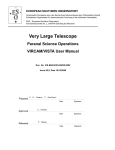
through the ICS, TCS and DCS modules. Figure 2 shows the context of the HOWFS with
respect to the other camera and telescope systems. The template sequencer scripts will be
responsible for despatching the appropriate commands to the image analysis process. The
DCS will store the acquired image in the Data Store as a FITS file. The OS will then append
data specific to the exposure, to the header of the FITS file before it is actually processed by
the HOWFS software.
During analysis, data will be logged using the CCS logging system, [RD9]. Data produced
from the analysis will also be stored in a coefficient file that can be processed offline to
produce the lookup table which is used in open loop correction of the primary mirror.
Figure 1: Layout of the images produced by the HOWFS filter on one of the IR
detector. (Not to scale)
University of Durham
Astronomical Instrumentation Group
HOWFSv3.4.doc
Rutherford
Appleton
Laboratory
IR Camera
-0002 High Order Wave Front
Sensor Software Design
Description
Doc. Number:
VIS-DES-UOD-06048-0002
Date:
12 April 2006
Issue:
3.4
Page:
Page 7 of 26
Author:
Nigel Dipper
Figure 2: Context diagram showing the interactions between the HOWFS
software and the Observation Software
The HOWFS Image Analysis process is known as vchoiaServer and is part of the vchoia
module. This process and its interaction with various other modules, is shown in detail in
Figure 3. The HOWFS image analysis is driven from sequencer scripts invoked by the ESO
Broker for Observation Blocks (BOB). It fits more closely with the ESO model of an on-line
data reduction task than with an instrument sub-system. The HOWFS database will be
contained within the wvcam environment and the database is created when the wvcam
environment is started. The vchoiaServer process connects to that database when it starts up.
The sequencer script will communicate with the vchoiaServer process by sending it messages
of the form:
msgSend wvcam vchoiaServer “VERSION” “”
msgSend wvcam vchoiaServer “SETUP” “-function HOWFS.STARPOS.X 32.0”
msgSend wvcam vchoiaServer “ANASTAR”
The vchoiaServer process replies with a 256-character-long string. Most replies contain
“OK”, “FAILED” or the data returned by the command, packed into a string. In the case of
the ANASTAR command, the resultant coefficients are not returned. They are instead copied
to file and to the database.
University of Durham
Astronomical Instrumentation Group
HOWFSv3.4.doc
Rutherford
Appleton
Laboratory
IR Camera
-0002 High Order Wave Front
Sensor Software Design
Description
Doc. Number:
VIS-DES-UOD-06048-0002
Date:
12 April 2006
Issue:
3.4
Page:
Page 8 of 26
Author:
Nigel Dipper
This document defines the interface with vchoia and the HOWFS database structure and
entries. The interface will be based on the EVH toolkit described in [RD4]. The interface will
be implemented by inheriting from the evhSTD_COMMANDS class which provides default
implementation for the standard commands.
Figure 3 Organisation of the vchoia Module and its Interaction with Other Vista
Camera (vc) Modules
3
WINDOWING AND CALIBRATION
Unlike the LOWFS, the HOWFS image analysis software makes use of a FITS file
containing the full set of 16 images from the IR image plane. The HOWFS curvature images
for this observation are contained in just one of these detector images. The relevant image is
identified in the VALIDEXT field in the image header.
The HOWFS software provides its own dark subtraction and flat-fielding capability. The
VIRCAM software will ensure that the relevant calibration frames are taken. The names of
the relevant files are contained within the database. The HOWFS software expects to find
dark and flat-fielded calibrations in these files. The format of these files is identical to that of
the curvature image data. It also expects to find a bad pixel mask file. This also has the same
format but with a 1 or 0 for each pixel to represent good and bad pixels.
University of Durham
Astronomical Instrumentation Group
HOWFSv3.4.doc
Rutherford
Appleton
Laboratory
IR Camera
4
-0002 High Order Wave Front
Sensor Software Design
Description
Doc. Number:
VIS-DES-UOD-06048-0002
Date:
12 April 2006
Issue:
3.4
Page:
Page 9 of 26
Author:
Nigel Dipper
OPERATIONAL STATES
The vchoiaServer process can be switched into one of the three standard states OFFLINE,
STANDBY and ONLINE. While in the ONLINE state, the process can also be in any one of
two sub states, IDLE and BUSY. Depending on the current state, some commands may not
be accepted. The various states may be defined as follows:
•
OFFLINE - The vchoiaServer process is not running or is in the OFFLINE state. The
database should be arranged to show the state of vchoiaServer as "OFFLINE" when
the wvcam environment is first started, and the process should have an exit handler
that sets the state to "OFFLINE" when it is shut down or dies. The server can be
switched to the OFFLINE state by the OFF command.
•
STANDBY - The vchoiaServer process is reading its configuration file, or has failed
to read its configuration file due to an error. The vchoiaServer process is up and
running but unable to process data. The SETUP, ANASTAR, CHECK and WAIT
commands are not accepted in this state. (In the event of an error, the ONLINE
command can make the process re-read the configuration file and go to the ONLINE
state).
•
ONLINE - The vchoiaServer process is running and able to process data. The
STANDBY command will make the process go into the STANDBY state (for
compatibility with the startup tool). Once in the ONLINE state, the process can be in
one of two sub-states:
o IDLE - No processing is taking place. The process can accept an ANASTAR
or SETUP command. The process transfers to the BUSY state on receipt of an
ANASTAR command. (NOTE: The SETUP command is likely to be very
fast, since it only sets parameters, so there is no need to change to the BUSY
state during a SETUP).
o BUSY - Processing is taking place. The process cannot accept a new
ANASTAR or SETUP command, and they will return an error. The process
returns to the IDLE sub-state when it has finished processing. A STOP or
ABORT command can be used to abort the processing and return to the IDLE
state immediately.
Figure 4 shows the state chart of process vchoiaServer.
University of Durham
Astronomical Instrumentation Group
HOWFSv3.4.doc
Rutherford
Appleton
Laboratory
IR Camera
-0002 High Order Wave Front
Sensor Software Design
Description
Doc. Number:
VIS-DES-UOD-06048-0002
Date:
12 April 2006
Issue:
3.4
Page:
Page 10 of 26
Author:
Nigel Dipper
Figure 4: Operational States of process vchoiaServer
5
5.1
DATA DESCRIPTION
Database Definitions
A database that represents the internal state of the vchoiaServer process is setup as shown in
Figure 5. The database is loosely based on the VLT software active optics design described in
[RD2]. Table 1 provides additional information on the objects listed in the database.
University of Durham
Astronomical Instrumentation Group
HOWFSv3.4.doc
Rutherford
Appleton
Laboratory
IR Camera
-0002 High Order Wave Front
Sensor Software Design
Description
Doc. Number:
VIS-DES-UOD-06048-0002
Date:
12 April 2006
Issue:
3.4
Page:
Page 11 of 26
Author:
Nigel Dipper
Figure 5 Database structure for module vchoia
University of Durham
Astronomical Instrumentation Group
HOWFSv3.4.doc
Rutherford
Appleton
Laboratory
IR Camera
-0002 High Order Wave Front
Sensor Software Design
Description
Doc. Number:
VIS-DES-UOD-06048-0002
Date:
12 April 2006
Issue:
3.4
Page:
Page 12 of 26
Author:
Nigel Dipper
Table 1: Definition of variables stored in the database.
Variable Name
status
state
substate
detector
badPixelMask
detAngle
Origin
Type
Description
Status
Statues
String
String
Standard state information
Detailed state information
Config
Config
String
Double
.imageId
imgFileName
Header
Setup
Integer
String
darkImgFile
flatImgFile
detector:window
Nx
Ny
STRX
STRY
setup:startUpCoeffs
active
Setup
Setup
String
String
Name of file storing bad pixel mask
Instrument angle with telescope axis in
degrees
Unique Id of this image
Name of file containing the images to
be analysed
Dark image filename (FITS)
Flat image filename (FITS)
Setup
Setup
Setup
Setup
double
double
double
double
Size of ROI in X dimension in pixels.
Size of ROI in Y dimension in pixels.
Lower left pixel of ROI in X dimension.
Lower left pixel of ROI in Y dimension.
Setup
vector of
booleans
modulus
Setup
angle
Setup
startpntModified
Setup
vector of
doubles
vector of
doubles
Boolean
Indicator to show if mode is to be fitted.
If not true, coefficients are used as bias
values.
Amplitude of mode in nm.
setup:nullCoeffs
nullModified
Setup
Boolean
nullSubtract
Setup
modulus
Config
angle
Config
setup:data
coeffFileName
altitude
Config
Header
University of Durham
Astronomical Instrumentation Group
HOWFSv3.4.doc
Rotation angle of mode in degrees.
(Only applicable to symmetric modes)
Flag to show that the startup
coefficients have been manually
modified.
Flag to show that null coefficients have
been modified and are not as in the null
file.
Boolean When flag is set, null coefficients are
subtracted from analysis result.
Vector of Amplitude of mode in nm
doubles
Vector of Rotation angle of mode in degrees
doubles
(Only applicable to symmetric modes)
String
Double
Rutherford
Appleton
Laboratory
Name of file to contain fit coefficients
Telescope altitude angle in degrees
IR Camera
-0002 High Order Wave Front
Sensor Software Design
Description
Doc. Number:
VIS-DES-UOD-06048-0002
Date:
12 April 2006
Issue:
3.4
Page:
Page 13 of 26
Author:
Nigel Dipper
mirrorTemp
preCentre.X
Header
Setup
Double
double
preCentre.Y
Setup
double
postCentre.X
Setup
double
postCentre.Y
Setup
double
starPos.X
Setup
double
starPos.Y
Setup
double
seeing
setup:modes
type
Header
double
Setup
Type of mode (Zernike or Elastic)
symmetry
Setup
order
Setup
name
Setup
Vector of
Strings
Vector of
integers
Vector of
integers
Vector of
Strings
fit:coeffs
active
modulus
angle
Status
Status
Status
vector
vector
vector
Indicator to show if mode was fitted
Amplitude of mode in nm.
Rotation angle in degrees. (Only
applicable to symmetric modes)
fit:simplexDiag
relativeTolerance
Status
double
iterationCount
funEvalsCount
executionTime
successFlag
Status
Status
Status
Status
integer
integer
double
Boolean
Relative tolerance between best and
worst solutions on completion.
Number of iterations used.
Number of function evaluations used.
Time taken for fit in seconds.
Flag to indicate if simplex analysis was
completed within maximum number of
iterations and function evaluations.
fit:preProcess
thresholdActive
Setup
Boolean
maxIntensity
totalIntensity
Status
Status
Integer
Integer
threshold
Setup
Integer
University of Durham
Astronomical Instrumentation Group
HOWFSv3.4.doc
Rutherford
Appleton
Laboratory
M1 mirror temperature in degrees C
Centre of pre-focal image in X
dimension in pixels.
Centre of pre-focal image in Y
dimension in pixels.
Centre of post-focal image in X
dimension in pixels.
Centre of post-focal image in Y
dimension in pixels.
X coordinate of star in focal plane
coordinates in mm
Y coordinate of star in focal plane
coordinates in mm
Seeing in arc seconds
Rotational symmetry of the mode
Order of the mode within its symmetry
Name of mode
If flag set to true, an error occurs if the
total intensity is less than the threshold.
Highest pixel value in both images.
Total intensity of all pixels in both
images.
Threshold for total intensity. If sum of
IR Camera
-0002 High Order Wave Front
Sensor Software Design
Description
badPixels
Status
Integer
algParameters:simplex
maxRelTolerance
Config
double
maxIterationCount
Config
integer
maxFunEvals
Config
integer
algParameters:raytracer:opticalConstants
pupilDiameter
Config
double
focalLength
Config
double
defocus
Config
double
obsRatio
Config
double
pixelSize
obsOffset.X
Config
Setup
double
double
obsOffset.Y
Setup
double
imgSizeInPixels
Config
integer
intensityRatio
Config
double
algParameters:raytracer:tracingEngine
gridSize
Config
integer
subGridSize
Config
integer
preBlur
Config
boolean
5.2
Doc. Number:
VIS-DES-UOD-06048-0002
Date:
12 April 2006
Issue:
3.4
Page:
Page 14 of 26
Author:
Nigel Dipper
two images is below this value and
thresholdActive is set, an error occurs.
Number of bad pixels in the two
images.
Stopping criteria for simplex algorithm.
Stop simplex analysis when relative
tolerance falls underneath this value.
Maximum number of simplex iterations
allowed.
Maximum
number
of
function
evaluations allowed.
Pupil diameter in metres.
Focal length in metres,
Defocus of WFS CCDs in mm.
Central obscuration ratio with respect to
pupil diameter
Pixel size in microns
Offset of the central obscuration in
CCD pixels in the X direction
Offset of the central obscuration in
CCD pixels in the Y direction
Image size in pixels
Intensity ratio of two images.
Size of grid of rays in pixels
Sub division of rays in pixels
Flag to indicate if images should be
blurred by seeing value. (Normally
TRUE).
Start up coefficients for HOWFS
The HOWFS software normally uses the expected null aberrations at a given point in the
focal plane as the starting point for the simplex. To do this, the HOWFS software requires a
file listing the values of null aberrations for each position on the focal plane at which a
HOWFS measurement will be made. These positions are specified in [AD8]. The null
aberrations relevant to the current HOWFS measurement are sent to vchoiaServer. If the
values sent are different to those held in the file, the nullModified flag (see below) should
also be set. When the analysis starts, and if the startpntModifed flag (see below) is not set, the
null aberrations are copied to the starting point aberrations in the data base. These are then
the start point for the simplex.
University of Durham
Astronomical Instrumentation Group
HOWFSv3.4.doc
Rutherford
Appleton
Laboratory
IR Camera
-0002 High Order Wave Front
Sensor Software Design
Description
Doc. Number:
VIS-DES-UOD-06048-0002
Date:
12 April 2006
Issue:
3.4
Page:
Page 15 of 26
Author:
Nigel Dipper
Various flags are provided to allow the analysis to be operated in a non standard way for
engineering and commissioning applications. Firstly, the null aberrations may be manually
specified. In this case, a flag (nullModified) is set to indicate that the database values differ
from the null aberration file. Secondly, the starting point aberrations may be manually
specified in the database. A flag (startpntModified) is set to indicate that the start point is
different to the null aberrations. The simplex algorithm can be a very slow process. To aid
convergence, this latter facility is provided to allow the simplex algorithm to be started close
to the expected results. Thirdly, the relevant null aberrations will not be subtracted from the
result if the nullSubtract flag is reset.
5.2.1 Null Aberrations File
The null aberrations sent to vchoiaServer are read from a null coefficients file. This file lists
the values of null aberrations for each position in the focal plane at which a HOWFS
measurement may be made. The format of the file will be that of an ASCII text table. Each
row of the table will correspond to a HOWFS position. The columns of the table are listed in
Table 2. The initial version of this file will be populated with values resulting from
modelling. The table will be updated during commissioning to contain relevant values for the
optical systems as built.
Table 2: Columns in the Null Aberrations file (ASCII text table)
Parameter
Name
x
y
modulus0
angle0
modulus1
angle1
Type
Description
double
double
double
double
double
double
X coordinate in the focal plane in mm.
Y coordinate in the focal plane in mm.
Modulus of aberration mode 0 in nm.
Rotation angle of aberration mode 0 in degrees.
Modulus of aberration mode 1 in nm.
Rotation angle of aberration mode 1 in degrees.
modulus{n-1}
angle{n-1}
double
double
Modulus of aberration mode n-1 in nm.
Rotation angle of aberration mode n-1 in degrees.
5.3
Detector Setup Parameters
The position of the images on the science detector are defined by specifying the centre of the
first defocused image in pixels in X and Y, and similarly for the second defocused image.
These positions are specified in the database entries: setup:data:preCentre and
setup:data:postCentre. Figure 6 shows the orientation of the HOWFS filter in one position.
The blue (lighter shaded) square represents the HOWFS filter, while the green squares
represent four of the IR detectors. The image axis is not exactly parallel with the radius of the
filter wheel, but is set at an angle such that the axis of the centres of the two defocused
images falls along the X axis of the selected detector for HOWFS positions where the Y
University of Durham
Astronomical Instrumentation Group
HOWFSv3.4.doc
Rutherford
Appleton
Laboratory
-0002 High Order Wave Front
Sensor Software Design
Description
IR Camera
Doc. Number:
VIS-DES-UOD-06048-0002
Date:
12 April 2006
Issue:
3.4
Page:
Page 16 of 26
Author:
Nigel Dipper
offset from the centre of the focal plane is a minimum. This has been exaggerated in the
diagram which is not to scale.
Y
Detector
Co-ordinates
X
Part of IR Camera
Focal Plane
IR Camera
Detectors
Image Axis
Filter Wheel R
First Defocused
Image
adius
Filter Wheel Axis
HOWFS Filter
IR Camera Full
Focal Plane
Figure 6: Orientation of the HOWFS Filter and Images.
University of Durham
Astronomical Instrumentation Group
HOWFSv3.4.doc
Rutherford
Appleton
Laboratory
IR Camera
5.4
-0002 High Order Wave Front
Sensor Software Design
Description
Doc. Number:
VIS-DES-UOD-06048-0002
Date:
12 April 2006
Issue:
3.4
Page:
Page 17 of 26
Author:
Nigel Dipper
Coefficient file
When the analysis is complete, the results are written to the database at fit:coeffs and also to a
coefficients file. The coefficients file name is given by database parameter
setup:data.coeffFileName. The VIRCAM software will provide a new filename for each
observation. The filename will conform to the ESO/VLT naming conventions [RD01] and
will be the same as that used for the associated observation with _COEFFS appended to the
filename. This file will be used to store data obtained during an analysis. It will be processed
offline to generate the look up tables required for correcting the shape of the primary mirror
in open loop mode. The format of the file will be that of a 2 column binary FITS table
containing the modulus and angle for each mode. Other parameters that are relevant to that
HOWFS observation are included as FITS header parameters. These are specified in Table 3.
(A full list of FITS header keywords used by the HOWFS software is given in Tables 6 and
7).
Table 3: Headers to the Coefficients FITS File
FITS Keyword
HOWFS.IMGFILE
Type
string
Description
Name of file containing defocused images. Included for
reference.
HOWFS.ID
integer
Unique id for each HOWFS observation
TEL M1 TMP
double
Temperature of Mirror in degrees Celsius when image
was acquired. (This can be retrieved from Image File
but included here for efficiency.)
TEL ALT
double
Telescope Altitude in degrees. (This can be retrieved
from Image File but included here for efficiency.)
HOWFS.DATE
string
Date and time when analysis was performed.
HOWFS.RTOL
double
The final relative tolerance value produced by the
simplex algorithm.
HOWFS.ITR
integer
Number of iterations performed by the simplex
algorithm,
HOWFS.SUCCESS
logical
Indicator to show whether simplex fit was successful
HOWFS.ACTIVE
Vector of The active modes vector.
Booleans
HOWFS.STARPOS.X double
X position of star in focal plane coordinates in mm
HOWFS.STARPOS.Y double
Y position of star in focal plane coordinates in mm
HOWFS.DETANGLE double
Angle of camera with respect to telescope in degrees
University of Durham
Astronomical Instrumentation Group
HOWFSv3.4.doc
Rutherford
Appleton
Laboratory
-0002 High Order Wave Front
Sensor Software Design
Description
IR Camera
6
Doc. Number:
VIS-DES-UOD-06048-0002
Date:
12 April 2006
Issue:
3.4
Page:
Page 18 of 26
Author:
Nigel Dipper
COMMAND INTERFACE BETWEEN VCHOIA AND OBSERVATION SOFTWARE
The commands listed in Table 4 are those which will be sent from the sequencer scripts to the
vchoiaServer process.
Table 4: Commands accepted by the vchoia process.
Command
ANASTAR
WAIT –id <id>
CHECK
SETUP
Standard Commands
STATE
STATUS
STOP / ABORT
PING
STANDBY
ONLINE
OFF
VERSION
KILL
EXIT
Optional Parameters Description
Start image analysis and return straight away with a string
containing a unique ID, starting at 1, or FAILED on error.
Returns ID <string>
If <id> does not match current ID, or on error, returns ERROR.
If BUSY, waits for analysis to complete and then returns OK.
If IDLE, returns OK straight away.
Note: OK does not guarantee that the Simplex converged.
Check the fit:simplexDiag.successFlag attribute to confirm.
Returns non-zero ID if busy, else 0.
Set the specified parameters to the specified values. The
keywords available for configuration are listed in Table 6.
-function <keyword> <value>
Define a list of keywords
[<keyword> <value>]
and values to be assigned.
-file <filename>
Define a file containing a
list of keywords and values
to be interpreted.
Return the state and substate as state.substate
Returns state as <string>
Returns the status as “STATE:” state.substate
Returns status as <string>
Stops Image Analysis
Returns OK
Ask the process to send back an OK reply
Returns OK
Switch to stand-by state
Returns OK
Re-read the configuration file and switch to on-line state.
Returns OK
Switch to OFFLINE state
Returns OK
Return the vchoia module version.
Returns version as <string>
Terminate the process
Shutdown the process cleanly.
University of Durham
Astronomical Instrumentation Group
HOWFSv3.4.doc
Rutherford
Appleton
Laboratory
IR Camera
-0002 High Order Wave Front
Sensor Software Design
Description
Doc. Number:
VIS-DES-UOD-06048-0002
Date:
12 April 2006
Issue:
3.4
Page:
Page 19 of 26
Author:
Nigel Dipper
Returns OK
7
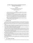
INTERNAL CLASS DIAGRAMS FOR VCHOIA.
The interface of module vchoia will be developed using the EVH toolkit, [RD4]. Figure 7
shows the hierarchical class structure of the module. This design hierarchy is loosely based
on that of the TCS auto guider workstation module described in [RD5]. Class “vchoiaCMDS”
will handle all the VLT standard commands. The default implementations provided by the
“evhSTD_COMMANDS” will be overridden as necessary. Class “vchoiaSETUP” will
handle the SETUP command since a default implementation is not provided. “vchoiaServer”
will co-ordinate the activity of the objects used within the process. Class “polySearch”
inherits from class amoeba. The latter implements the “SIMPLEX” algorithm as described in
[RD7]. Class “rayTracer” is used for raytracing the defocused images. Raytracing as used
here is described in [AD5]. Class “polyTables” will store the first order partial derivatives of
the polynomials of the modes that will be fitted during the image analysis. The modes are
listed in section 11. After the WAIT command has completed, the new coefficients may be
read from the HOWFS database or from the specified coefficients file.
Once the VIRCAM software has made an observation using the HOWFS filter and saved the
resulting image, Figure 8 shows the exchange of commands between vchoiaServer, the
VIRCAM software and the classes implementing the actual image analysis. A higher level
diagram showing interaction with the Sequencer can be seen in [AD03 - Fig.14]. The
VIRCAM software will send SETUP commands to adjust processing control parameters.
Image analysis is then triggered by sending command ANASTAR. vchoiaServer reads the
image file, obtains the image size from the database and the seeing value from the image file
header. The star X,Y position in the focal plane and the positions of the pair of images on the
detector are taken from the database. vchoiaServer then starts the analysis process and returns
a unique ID straight away to the Sequencer, or an error (FAILED) on error. While analysis is
taking place, the Observation Software can query vchoiaServer to see if analysis has been
completed using the CHECK command. Alternatively the Observation Software can issue the
WAIT command, and a reply will be sent back as soon as the analysis completes.
University of Durham
Astronomical Instrumentation Group
HOWFSv3.4.doc
Rutherford
Appleton
Laboratory
IR Camera
-0002 High Order Wave Front
Sensor Software Design
Description
Doc. Number:
VIS-DES-UOD-06048-0002
Date:
12 April 2006
Issue:
3.4
Page:
Page 20 of 26
Author:
Nigel Dipper
evhSIMPLE_TASK
evhDB_TASK
amoeba
evhSTD_COMMANDS
vchoiaSetup
vchoiaServer
polySearch
1
1
polyTables
vchoiaCMDS
rayTracer
1..*
1
Figure 7 Class hierachy within the vchoia module
University of Durham
Astronomical Instrumentation Group
HOWFSv3.4.doc
Rutherford
Appleton
Laboratory
IR Camera
-0002 High Order Wave Front
Sensor Software Design
Description
Doc. Number:
VIS-DES-UOD-06048-0002
Date:
12 April 2006
Issue:
3.4
Page:
Page 21 of 26
Author:
Nigel Dipper
Figure 8 Exchange of messages between the vchoia classes when doing an
analysis.
University of Durham
Astronomical Instrumentation Group
HOWFSv3.4.doc
Rutherford
Appleton
Laboratory
IR Camera
8
-0002 High Order Wave Front
Sensor Software Design
Description
Doc. Number:
VIS-DES-UOD-06048-0002
Date:
12 April 2006
Issue:
3.4
Page:
Page 22 of 26
Author:
Nigel Dipper
DEPLOYMENT
The HOWFS image analysis software, including the vchoiaServer process, will be contained
within the vchoia module. The HOWFS database will be contained within the /dbl
subdirectory of the vchoia module. This vchoia module will be deployed using the pkgin tool,
[RD6]. The vchoiaServer process will run on the instrument workstation and on the same
VLT environment (wvcam), [AD7], as the observation software. The pkgin tool will be
responsible for creating the necessary VLT environments and for building the database. The
HOWFS database will be contained within the /dbl subdirectory of the vchoia module which
is assumed to be included in the wvcam database contained in the vcins module as shown in
Figure 3. The configuration file and null aberrations file are stored in the vchoia module.
9
TESTING
Testing of the software will be done using ESO’s tools for automated testing, TAT, [RD8].
TAT provides a set of tools that can be used as part of a script to test software components.
TAT will also configure temporary VLT environments in which to perform the tests. With
TAT it is possible to create a battery of tests, which can be run each time the software is
updated, to make sure that any existing functionality is not lost. TAT can make bugs
identifiable by providing repeatable tests that show the occurrence of a specific error.
The module will be tested as follows:
1) Typical images as observed by the HOWFS during operation will be provided for
testing. (A mixture of simulated and experimental images from the lab will be used).
2) Unsuitable images will be provided to see if they can be reliably rejected before
starting a time consuming analysis process.
3) Test cases for all the implemented commands will be provided.
4) Pairs of simulated defocused images with known aberrations will be used to test the
algorithm.
Test data will be saved within the vchoia module in the /test subdirectory. To save bandwidth
during network module transfers, this data may need to be compressed. It can be
uncompressed during a ‘make’ within the /test directory.
10 APPENDIX A: DATA DICTIONARY SPECIFICATIONS
The ESO VLT software standard makes use of keyword dictionaries to define the meaning,
data type and format of keywords used within the software. The relevant HOWFS dictionary
will be contained within the dicVIRCAM module. The keywords listed in Table 6 are used
during configuration of the software module (CFG) and setup prior to an analysis (SETUP).
The keywords are designed to meet the requirements of [RD10].
Some of the SETUP keywords will be embedded in the FITS header of the image file and
these have been marked as HDR. By logging some of these parameters in the image file
University of Durham
Astronomical Instrumentation Group
HOWFSv3.4.doc
Rutherford
Appleton
Laboratory
IR Camera
-0002 High Order Wave Front
Sensor Software Design
Description
Doc. Number:
VIS-DES-UOD-06048-0002
Date:
12 April 2006
Issue:
3.4
Page:
Page 23 of 26
Author:
Nigel Dipper
header, the analysis can be run at any time. The HDR keywords represent metadata about the
image which is produced when the image is acquired and will therefore remain unchanged
throughout the existence of the image. The keywords used in the ESO FITS file, have to
comply with ESO’s extended hierarchical FITS keywords. A straight forward conversion can
be performed on the keywords marked as HDR to derive the ESO compliant FITS keywords.
Two examples are given in Table 5.
Table 5: Converting from setup keywords to ESO’s Hierarchical FITS keywords
SETUP KEYWORD
HOWFS.OBSOFFX
HOWFS. STRTPNT.MODMODE3
ESO EXTENDED HIERARCHICAL FITS KEYWORD
HIERARCH ESO INS HOWFS OBSOFFX
HIERARCH ESO INS HOWFS STRTPNT MODMODE3
The SETUP command of vchoia will parse all three types of keywords. During configuration,
the keywords will normally be passed through a file, rather than on an individual basis. The
keywords in the header of the image file will override any previous value sent through the
SETUP commands. The vchoia module will also make use of keywords defined by other
subsystems. These are listed in Table 7.
Table 6: Keywords used by the HOWFS software.
KEYWORD
HOWFS.PUPDIA
HOWFS.DEFOCUS
HOWFS.OBSRATIO
PURPOS
E
CFG
CFG
CFG
Type
double
double
double
Unit
m
mm
HOWFS.IMGSIZE
HOWFS.PIXSIZE
HOWFS INTRATIO
CFG
CFG
CFG
integer
double
double
pixels
Um
HOWFS.GRIDSIZE
CFG
integer
Pixels
HOWFS.SUBGDSZ
CFG
integer
Pixels
HOWFS.NAMEMODi
HOWFS.TYPEMODi
CFG
CFG
string
integer
HOWFS.SYMMODi
CFG
logical
HOWFS.ORDMODi
HOWFS.NULLFILE
CFG
CFG
integer
string
HOWFS.NULLMOD
CFG
logical
T/F
HOWFS.NULLSUB
CFG
logical
T/F
HOWFS.NULLABER.MODMODEi
CFG,
SETUP
double
nm
University of Durham
Astronomical Instrumentation Group
HOWFSv3.4.doc
Rutherford
Appleton
Laboratory
T/F
Comment
Pupil Diameter
Image Defocus
Central obscuration ratio with
respect to pupil diameter
Pixel size in microns
Intensity Ratio between
defocused images due to
beam splitter
Grid size of rays used by
raytracer in pixels
Subdivision of rays
Name of mode to fit
Type of mode. (Zernike or
Elastic)
Is this a symmetic mode? i.e.
cos and sin terms
Order of mode
File containing null values for
the aberrations against
radius.
Database null aberrations
have been modified
Subtract null aberrations from
results.
Modulus of null aberration
mode i
IR Camera
-0002 High Order Wave Front
Sensor Software Design
Description
HOWFS.NULLABER.ANGMODEi
HOWFS.MAXRTOL
HOWFS.RTOL
HOWFS.MAXITR
CFG,
SETUP
CFG,
SETUP
HDR
double
Doc. Number:
VIS-DES-UOD-06048-0002
Date:
12 April 2006
Issue:
3.4
Page:
Page 24 of 26
Author:
Nigel Dipper
degrees
double
double
CFG,
SETUP
HDR
integer
HOWFS.PREBLUR
CFG,
SETUP
logical
T/F
HOWFS.USEMODi
HOWFS.IMGFILE
SETUP
SETUP
logical
string
T/F
HOWFS.DARKFILE
HOWFS.FLATFILE
HOWFS.COFILE
SETUP
SETUP
SETUP
string
string
string
HOWFS.PATH
SETUP
string
HOWFS.BADMASK
SETUP
string
HOWFS.OBSOFF.X
double
mm
double
mm
double
mm
double
mm
double
pixels
double
pixels
double
pixels
double
degrees
HOWFS.STRTPNT.MODMODEi
SETUP,
HDR
SETUP,
HDR
SETUP,
HDR
SETUP,
HDR
SETUP,
HDR
SETUP,
HDR
SETUP,
HDR
SETUP,
HDR
SETUP
double
nm
HOWFS.STRTPNT.ANGMODEi
SETUP
double
degrees
HOWFS.STRTPNT.MOD
logical
T/F
HOWFS.BADPIX
SETUP,
CFG
HDR
integer
HOWFS.SUCCESS
HDR
logical
HOWFS.NMODES
HDR
integer
HOWFS.ITR
HOWFS.OBSOFF.Y
HOWFS.STARPOS.X
HOWFS.STARPOS.Y
HOWFS.PREIMG.X
HOWFS.PREIMG.Y
HOWFS.POSTIMG.X
HOWFS.POSTIMG.Y
University of Durham
Astronomical Instrumentation Group
HOWFSv3.4.doc
integer
Rutherford
Appleton
Laboratory
T/F
Angle of null aberration mode
i
Maximum Relative Tolerance
Final relative tolerance
achieved by the simplex
Maximum Iteration Count of
simplex algorithm
Final iteration count from the
simplex
Flag to indicate whether
observed images must be
blurred
Indicator to fit mode
File containing defocused
images
File containing a dark image
File containing a flat image
File to store measured coeffs
in with additional data
Directory path to where the
above files are kept.
File containing mask with bad
pixels indicated.
Offset of the central
obscuration in X direction
Offset of the central
obscuration in Y direction
X position of star in Focal
Plane co-ordinates
Y position of star in Focal
Plane co-ordinates
Detector X co-ordinate of first
defocused Image
Detector Y co-ordinate of first
defocused Image
Detector X co-ordinate of
second defocused Image
Detector Y co-ordinate of
second defocused Image
Starting value of the modulus
for the simplex algorithm
Starting value of the angle for
the simplex algorithm
If T, start-point coefficients
have been modified
Number of bad pixels in
analysed images
Flag to indicate if simplex
converged
Number of modes fitted by the
simplex
IR Camera
-0002 High Order Wave Front
Sensor Software Design
Description
HOWFS.PREBLUR
SETUP,
CFG
HDR
HOWFS.DATE
logical
T/F
string
Doc. Number:
VIS-DES-UOD-06048-0002
Date:
12 April 2006
Issue:
3.4
Page:
Page 25 of 26
Author:
Nigel Dipper
Flag to indicate if blurring is to
be applied
Date/time when coefficients
were produced
Table 7: Keywords needed by HOWFS software but defined by other
subsystems
KEYWORD
TEL FOCU LEN
TEL AMBI FWHM START
TEL AMBI FWHM END
TEL GUID FWHM
TEL ALT
TEL TH M1 TMP
DET CHIP ID
VALIDEXT
PURPOSE
CFG
HDR
HDR
HDR
HDR
HDR
SETUP
SETUP
Type
double
double
double
double
double
double
string
string
Units
m
arcSec
arcSec
arcSec
degrees
degrees
Comments
Focal length of telescope
Seeing at start of acquiring images
Seeing at end of acquiring images
Seeing derived from auto-guider
Altitude of telescope
Temperature of M1 mirror
Detector ID of this image
ID of detector image that contains
HOWFS images
11 APPENDIX B COEFFICIENTS TO FIT
The following coefficients will be fitted using the simplex algorithm. The actual polynomials
are listed in [AD4].
Index
0
1
2
3
4
5
6
7
8
9
10
11
12
Mode
Tilt
Defocus
Coma
e(2,1)
e(3,1)
e(4,1)
e(2,2)
Spherical
e(1,2)
e(5,1)
5th Order Spherical Defocus
e(6,1)
e(3,2)
Constituent Modes
Z2,Z3
Z4
Z7,Z8
e(2,1)sin, e(2,1)cos
e(3,1)sin, e(3,1)cos
e(4,1)sin, e(4,1)cos
e(2,2)sin, e(2,2)cos
Z11
e(1,2)sin, e(1,2)cos
e(5,1)sin, e(5,1)cos
Z22
e(6,1)sin, e(6,1)cos
e(3,2)sin, e(3,2)cos
Comments
Ignore these modes
M1 mirror mode
M1 mirror mode
M1 mirror mode
M1 mirror mode
M1 mirror mode
M1 mirror mode
M1 mirror mode
M1 mirror mode
12 APPENDIX C LOG FILES
The HOWFS will also log the following events to log files using the CCS logging system,
[RD9]. Each event will be time stamped. Two types of log files will be generated depending
on the mode of operation:
University of Durham
Astronomical Instrumentation Group
HOWFSv3.4.doc
Rutherford
Appleton
Laboratory
IR Camera
•
•
-0002 High Order Wave Front
Sensor Software Design
Description
Doc. Number:
VIS-DES-UOD-06048-0002
Date:
12 April 2006
Issue:
3.4
Page:
Page 26 of 26
Author:
Nigel Dipper
Operational log file
o A record of start-up and shutdown times
o Each command received from the OS
o A description of each measurement made and the wave front coefficients
derived
Engineering log file
o Command received from the OS. (including parameters)
o Informational messages (when running in VERBOSE mode)
o Error messages and fault conditions, with diagnostic information
__oOo__
University of Durham
Astronomical Instrumentation Group
HOWFSv3.4.doc
Rutherford
Appleton
Laboratory