1
User manual for
UEIDAQ for LabVIEW®
High Performance Data Acquisition Software for IBM PC, PC/XT, PC/AT and compatible Computer Systems.
Copyright 1993-1997 Keyview Investments Limited
All right reserved. No part of this publication may be reproduced, stored in a retrieval system, or transmitted, in any
form by any means, electronic, mechanical, by photocopying, recording, or otherwise without prior written permission.
Third edition.
June 1994
June 1994 Printing
Information furnished in this manual is believed to be accurate and reliable; however no responsibility is assumed for its
use, nor for any infringements of patents or other rights of third parties which may result from its use.
IBM, IBM PC/XT/AT and IBM PS/2 are trademarks of International Business Machine Corporation.
BASIC is a trademark of Dartmouth College.
Microsoft is a trademark of Microsoft Corporation.
LabVIEW® is a trademark of National Instruments Corporation.
Product and company names listed are trademarks or trade names of their respective companies.
Table of Contents
Preface
1. Getting started
1
1.1. Introduction
1
1.2. Boards supported
1
1.3. Windows support
4
1.4. Functions supported
5
1.5. Installing the UEIDAQ LabVIEW® driver
6
1.6. Driver structure
6
1.7. Examples
7
2. Using the LabVIEW® VIs
9
2.1. Introduction to the VIs
9
2.2. VI Naming
9
2.3. How the VIs view hardware
9
2.4. Data acquisition VI operation
10
2.5. Multiple execution paths
11
2.6. Channel addressing
11
2.7. Error codes
11
2.8. Quick reference
12
3. Configuration functions
15
3.1. Configuration VI introduction
15
3.2. Configure board
15
3.3. AD Chan Configure
17
3.4. DA Chan Configure
18
3.5. DIO Port Configure
19
3.6. Version
4. Easy I/O functions
19
21
4.1. Easy I/O VI introduction
21
4.2. AD Easy Wave
21
4.3. AD Trig Wave
22
4.4. DA Easy Wave
24
5. Analog input functions
27
5.1. Analog input VI introduction
27
5.2. AD Chan In
27
5.3. AD Wave In
28
5.4. AD Check
29
5.5. AD Close to Integer
30
5.6. AD Close to Single
30
6. Analog Output functions
33
6.1. Analog output VI introduction
33
6.2. DA Chan Out
33
6.3. DA Wave Out
34
6.4. DA Check
35
6.5. DA Close
36
7. Digital I/O functions
37
7.1. Digital I/O VI introduction
37
7.2. DIO Port In
37
7.3. DIO Port Out
38
8. Utility functions
39
8.1. Utility VI introduction
39
8.2. Software Trigger
39
8.3. String To Int Chan List
40
8.4. Synchronize
40
9. Signal processing VIs
43
9.1. Signal processing introduction
43
9.2. FFT
43
9.3. Inverse FFT
44
9.4. Hilbert transform
44
9.5. Inverse Hilbert transform
45
9.6. Chirp-Z
45
9.7. Convolution
46
9.8. Zero pad
46
10. Window VIs
47
10.1. Windows VI introduction
47
10.2. Hamming window
48
10.3. Hanning window
48
10.4. Blackman-Harris window
49
11. Spectrum analysis VIs
51
11.1. Spectrum analysis introduction
51
11.2. Power Spectrum
52
11.3. Linear Spectrum
52
11.4. Power Chirp-Z Spectrum
52
11.5. Linear Chirp-Z Spectrum
53
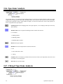
11.6. Spectrum Analysis
54
11.7. Chirp-Z Spectrum Analysis
54
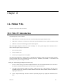
12. Filter VIs
57
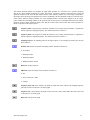
12.1. Filter VI introduction
57
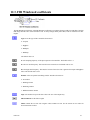
12.2. FIR coefficients
58
12.3. FIR Windowed coefficients
59
12.4. FIR Filter
60
Index
Preface
This manual is written for users of UEIDAQ LabVIEW ® for Windows Drivers software package. It provides all
information necessary to successfully use the supplied driver software in conjunction with LabVIEW®.
This manual assumes:
•
That you have a basic knowledge of electronic circuitry and measurement techniques.
•
That you are familiar with the host PC which you are using.
•
That you are familiar with LabVIEW®.
•
That you have read chapters 1 thru 4 of the user manual accompanying your WIN-30, UEI-30, UEI-126, UEI127, UEI-14, UEI-36, UEI-192, or UEI-66
The manual contains the following sections.
Chapter 1 - Getting Started.
•
Chapter 1 contains an overview of UEIDAQ LabVIEW ® Driver software package, and its capabilities.
Chapter 2 - Using the LabVIEW® VIs.
•
Chapter 2 provides a tutorial on the use of the UEI LabVIEW ® VIs.
Chapter 3 - Configuration functions.
•
Chapter 3 discusses the board configuration functions.
Chapter 4 - Easy I/O functions.
•
Chapter 4 discusses the Easy I/O functions. These are simple, high level analog I/O functions, that provide a
quick way to satisfy most commonly encountered data acquisition requirements.
Chapter 5 - Analog input functions.
•
Chapter 5 discusses the low level analog input functions. These are somewhat more complex functions that allow
more flexibility than the easy I/O functions
Chapter 6 - Analog output functions.
•
Chapter 6 discusses the low level analog output functions.
Chapter 7 - Digital I/O functions.
•
Chapter 7 discusses the Digital I/O functions. These functions provide digital input and output functions.
Chapter 8 - Utility functions.
•
Chapter 8 discusses the utility functions. These functions provide various services, such as synchronization and
format conversion, that do not access data acquisition hardware directly.
Chapter 9 - Signal processing VIs.
•
Chapter 9 discusses the signal processing VIs. These functions provide the means to analyze your data once it is
acquired. They include FFT, IFFT and Hilbert transforms.
Chapter 10 - Window VIs.
•
Chapter 10 discusses the window VIs. Window operations are used both for filter design and spectrum analysis.
Chapter 11 - Spectrum analysis VIs.
•
Chapter 11 discusses the spectrum analysis VIs. These are used to estimate the spectral content of a sampled
signal.
Chapter 12 - Filter VIs.
•
Chapter 12 discusses the Filter VIs. These VIs are used to filter waveforms.
Chapter 1
1. Getting started
This chapter introduces the UEIDAQ LabVIEW ® Driver system.
1.1. Introduction
UEIDAQ LabVIEW ® Driver software has been written to allow the easy use of all WIN-30, UEI-30, UEI-126, UEI127, UEI-14, UEI-36, UEI-192 and UEI-66 functions from LabVIEW ® for Windows V3 or later.
1.2. Boards supported
UEIDAQ LabVIEW ® Driver package supports the following boards:
•
All analog input boards; the WIN-30 and UEI-30 series boards and the UEI-126 and UEI-127.
•
All UEI digital I/O boards, including the UEI-14, UEI-36 and UEI-192.
•
All UEI analog output boards, including the UEI-66.
The complete range of UEI analog input boards consist of three series of boards, the "old" series, the 16-bit series, and
the 32-bit or "WIN" series.
1.2.1. Old series boards.
The old series of boards consists of three boards:
1.2.1.1. UEI-26
The UEI-26 is the original board in the range. It is an analog input board, with 16 single ended inputs, and a
programmable clock. Maximum throughput is 25 kHz.
1.2.1.2. UEI-30
The UEI-30 has the same analog input capability as the UEI-26, and is fully compatible with the UEI-26, but has several
additional capabilities:
i.
Digital I/O. There are 24 digital I/O lines, each of which may be programmed as an input or an output.
Getting Started
1
ii.
Two 12-bit D/A converters with either bipolar or monopolar outputs.
iii.
Two 8-bit D/A converters, also with either bipolar or monopolar outputs.
1.2.1.3. UEI-39
The UEI-39 shares all the characteristics of the UEI-30, but adds several enhancements:
i.
Single channel DMA operation. This boosts throughput to 80 kHz on a single input channel.
ii.
Improved analog input specification. The UEI-39 features high impedance inputs.
iii.
Improved status read back. The UEI-39 has an extra conversion status bit, which simplifies programming, and
can increase throughput considerably.
iv.
Improved interrupt operation. The UEI-26 and UEI-30 could "lose" interrupts. The UEI-39 cannot.
Note
Old series boards are supported only in PC or PC/XT machines and 100% compatibles. Operation in PC/AT or
compatible machines is not supported.
1.2.2. 16-bit series boards.
The 16-bit series of boards consists of eight boards. All 16-bit series boards are supported in PC/AT systems, and are
fully compatible with all old series boards.
1.2.2.1. UEI-30B
The UEI-30B forms the basis of the "new" UEI-30 range. It features 30 kHz throughput, and advanced DMA circuitry
which allows multi-channel analog input operations at full throughput.
1.2.2.2. UEI-30C
The UEI-30C has all the features of the UEI-30B, but features an A/D throughput of 100 kHz.
1.2.2.3. UEI-30D
The UEI-30D is a development of the UEI-30C, with A/D throughput of 200 kHz. It is designed for use in PC/AT and
AT compatible PCs. In addition to improved throughput, the UEI-30D also contains FIFO buffers for A/D data, for
improved operation in conjunction with multi-tasking operating systems such as OS/2.
1.2.2.4. UEI-30DS
The UEI-30DS is a development of the UEI-30D, and is identical in operation and capabilities to the UEI-30D, except
for the addition of simultaneous sample and hold operation on all 16 input channels. The available analog input ranges
of the UEI-30DS have also been modified to support this capability.
1.2.2.5. UEI-30DS/4
The UEI-30DS/4 is a low cost version of the UEI-30DS, with only four simultaneously sampled input channels. In all
other respects it is identical to the UEI-30DS.
2
Getting started
1.2.2.6. UEI-30PG
The UEI-30PG L and UEI-30PGH are essentially the same as the UEI-30D, but feature programmable gain. The UEI30PGL has gains of 1, 10, 100 and 1000, while the UEI-30PGH has gains of 1, 2, 4 and 8 available.
1.2.2.7. UEI-126
The UEI-126 is a low cost very high performance board intended for use primarily in laptop PCs. It features 16 single
ended analog inputs, two analog outputs, 8 digital inputs, 8 digital outputs, and a programmable clock. Maximum
throughput is 50 kHz.
1.2.2.8. UEI-127
The is a low cost very high performance simultaneous sampling board intended for use primarily in laptop PCs. It
features 4 single ended, simultaneously sampled analog inputs, two analog outputs, 8 digital inputs, 8 digital outputs,
and a programmable clock. Maximum throughput is 100 kHz.
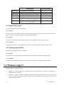
1.2.3. 32-bit series boards.
The 32-bit series of boards consists of eight boards. All 32-bit series boards are supported in PC, PC/XT and PC/AT
systems, and are fully compatible with the 16-bit series of boards.
The first part of the "32-bit" series of boards is the WIN-30 series, which features input resolution of 12 bits:
Analog Inputs
Analog Outputs
WIN-30D
16 single ended, 12-bit resolution
-
WIN-30DA
16 single ended, 12-bit resolution
Two 12-bit, two 16-bit
WIN-30DS
16 simultaneously sampled, 12-bit resolution
Two 12-bit, two 16-bit
WIN-30DS/4
4 simultaneously sampled, 12-bit resolution
Two 12-bit, two 16-bit
WIN-30PGL
16 single ended/8 differential, programmable
gains of 1, 10, 100, 1000, 12-bit resolution
Two 12-bit, two 16-bit
WIN-30PGH
16 single ended/8 differential, programmable
gains of 1, 2, 4, 8, 12-bit resolution
Two 12-bit, two 16-bit
WIN-30PGSL
16 single ended/8 differential, programmable
gains of 1, 10, 100, 1000, 12-bit resolution,
simultaneous sampling
Two 12-bit, two 16-bit
WIN-30PGSH
16 single ended/8 differential, programmable
gains of 1, 2, 4, 8, 12-bit resolution,
simultaneous sampling
Two 12-bit, two 16-bit
The WIN-30 series of boards is also available in 16 bit analog input resolution, as the WIN-3016 series, detailed below:
Getting Started
3
Analog Inputs
Analog Outputs
WIN-3016D
16 single ended, 16-bit resolution
-
WIN-3016DA
16 single ended, 16-bit resolution
Two 12-bit, two 16-bit
WIN-3016DS
16 simultaneously sampled, 16-bit resolution
Two 12-bit, two 16-bit
WIN-3016DS/4
4 simultaneously sampled, 16-bit resolution
Two 12-bit, two 16-bit
WIN-3016PGL
16 single ended/8 differential, programmable
gains of 1, 10, 100, 1000, 16-bit resolution
Two 12-bit, two 16-bit
WIN-3016PGH
16 single ended/8 differential, programmable
gains of 1, 2, 4, 8, 16-bit resolution
Two 12-bit, two 16-bit
1.2.4. Digital I/O boards
The following digital I/O boards are supported:
1.2.4.1. UEI-14
The UEI-14 has six 8-bit digital I/O ports. Each port can be programmed as either an input or output. The UEI-14 also
features 3 counter-timer devices, but these are not supported by UEIDAQ.
1.2.4.2. UEI-36
The UEI-36 has three 8-bit digital I/O ports. Each port can be programmed as either an input or output.
1.2.4.3. UEI-192
The UEI-192 has twenty four 8-bit digital I/O ports. Each port can be programmed as either an input or output.
1.2.5. Analog output boards
The following analog output boards are supported:
1.2.5.1. UEI-66
The UEI-66 has twelve analog outputs, each of which can be configured for monopolar or bipolar outputs..
1.2.5.2. UEI-66A
The UEI-66A has eighth analog outputs, each of which can be configured for monopolar or bipolar outputs..
1.3. Windows support
Windows support is provided as follows:
4
•
Windows 3.1 enhanced mode only is supported. Operation under Windows 3 or earlier, or in Windows 3.1
standard mode is not possible.
•
Windows 3.1 support is via a DLL (Dynamic Linked Library ) and a virtual device driver (Vxd). Both of these
must be accessible to Windows for the driver system to operate. Installation of the DLL and Vxd are discussed
further later in this manual.
Getting started
•
A minimum configuration of a 386 processor and 4 MBytes of memory is required. A 386DX or 486 processor
and 8 Mbytes of memory are recommended.
1.4. Functions supported
Functions supported depend on two factors:
•
The version of UEIDAQ installed on your machine. Depending on the product that you purchased, your version
of UEIDAQ may support only certain boards. Versions of UEIDAQ that are supplied with a specific board
always support that board, but may or may not support other UEI products. Consult the documentation supplied
with the version of UEIDAQ that you are using.
•
The board in question. Various boards support only certain functio ns. The list below provides a rough guide:
1.4.1. UEI-26 and UEI-30
Diagnostics, analog output on all four D/A outputs, obtain a single A/D sample, obtain a series of A/D samples on either
a single or multiple channels, digital I/O.
1.4.2. UEI-39
Diagnostics, analog output on all four D/A outputs, obtain a single A/D sample, obtain a series of A/D samples on either
a single or multiple channels, single channel DMA operation, digital I/O.
1.4.3. UEI-30B and UEI-30C
Diagnostics, analog output on all four D/A outputs, obtain a single A/D sample, obtain a series of A/D samples on either
a single or multiple channels, either single channel or multiple channel DMA operation, digital I/O.
1.4.4. UEI-30D
Diagnostics, analog output on all four D/A outputs, obtain a single A/D sample, obtain a series of A/D samples on either
a single or multiple channels, either single channel or multiple channel DMA operation, gap free dual DMA channel
operation, digital I/O.
1.4.5. UEI-30DS
The UEI-30DS and UEI-30DS/4 share all of the abilities of the UEI-30D, and appear identical to software. The only
difference in operation comes about in block mode operation, where all sampled channels are sampled simultaneously.
All references in this manual to UEI-30D boards also applies to UEI-30DS and UEI-30DS/4 boards, unless specifically
stated otherwise.
1.4.6. UEI-30PG
The UEI-30PG shares all the functions of the UEI-30D, but in addition allows the gain of each analog input channel to
be individually set.
1.4.7. UEI-126 and UEI-127
Diagnostics, analog outputs, obtain a single A/D sample, obtain a series of A/D samples on either a single or multiple
channels, digital I/O, and waveform generation.
Getting Started
5
1.4.8. WIN-30 series
Diagnostics, obtain a single A/D sample, obtain a series of A/D samples on either a single or multiple channels, either
single/dual channel DMA or rep string operation, gap free dual DMA channel operation, digital I/O.
1.5. Installing the UEIDAQ LabVIEW ® driver
The LabVIEW ® driver installs automatically. Follow these steps:
i.
Place the distribution diskette in drive A: or B:.
ii.
Ascertain the name of the directory that LabVIEW® is installed to. This is usually C:\LABVIEW.
iii.
Start Windows.
iv.
Go to the Windows File menu and select Run.
v.
Enter A:SETUP as the program to run.
vi.
Press the enter key.
vii. The setup program will then run. Answer any questions that it asks.
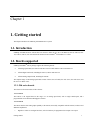
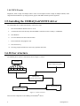
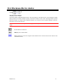
1.6. Driver structure
The UEIDAQ driver system is structured as shown in figure 1.1 below:
LabVIEW
Other Windows Programs
UEIDAQ for LabVIEW VI's
UEIDAQ.DLL
(Dynamic Link Library)
Data Acquisition Board
UEIDAQV.386
(Virtual Device Driver)
Figure 1.1. Driver structure.
There are three components to the UEIDAQ for LabVIEW ® drivers:
6
Getting started
•
The UEIDAQ LabVIEW ® VIs. These VIs are the part of the driver system that is visible to LabVIEW ®. You
create your application by interconnecting these VIs in LabVIEW ®. In essence, the VIs are high level wrappers
for calls to the UEIDAQ DLL
•
The UEIDAQ DLL . All I/O requests for any UEI board under Windows 3.1 go via this DLL. It serves to
synchronize all driver activity, and allows full multi-tasking.
•
The UEIDAQV virtual device driver . This driver handles all high speed I/O operations, as well as providing
access Ring 0 access to the DLL.
1.6.1. Driver Requirements
Windows support is provided as follows:
i.
Windows 3.1 enhanced mode only is supported. Operation under Windows 3 or earlier, or in Windows 3.1
standard mode is not possible.
ii.
A minimum configuration of a 386 processor and 4 MBytes of memory is required. A 386DX or 486 processor
and 8 Mbytes of memory are recommended.
iii.
Windows 3.1 support is via a DLL (Dynamic-Link Library) and a virtual device driver (Vxd). Both of these must
be accessible to Windows for the driver system to operate. The DLL is UEIDAQ.DLL, and the Vxd is
UEIDAQV.386
iv.
Windows locates a dynamic-link library by searching the same directories it searches to find an application
module. For Windows to the find the library, it must be in one of the following directories , which Windows
searches in the order listed:
a) The current directory.
b) The Windows directory (the directory containing WIN.COM).
c) The Windows system directory (the directory containing such system files as GDI.EXE).
d) Any of the directories listed in the PATH environment variable.
e) Any directory in the list of directories mapped in a network.
v.
Microsoft recommends that DLL's be loaded into the Windows system directory. This is where the default
installation program places UEIDAQ.DLL, but any other valid position is acceptable
vi.
In order for Windows to load the UEIDAQV Vxd , the following line must appear in the [386ENH] section of the
Windows SYSTEM.INI file : "device=c:\uei\ueidaqv.386". This assumes that the Vxd is in the default location,
the c:\UEI directory. If it is not, then the line should be modified accordingly. Once again, this is automatically
done by the default installation program.
1.7. Examples
A wide variety of example VI that show how to use the various functions described in this manual may be found in the
“VI.LIB\UEI\EXAMPLES” VI in your Labview directory. These include waveform input and output, spectrum analysis
and data analysis programs.
Getting Started
7
Chapter 2
2. Using the LabVIEW ® VIs
This chapter discusses the basic operation of the driver VIs, and how to interconnect them.
2.1. Introduction to the VIs
The VIs supplied with UEIDAQ LabVIEW ® driver system fall into two groups:
i.
Data acquisition VIs. These VIs access the hardware of the data acquisition board, and actually perform data
acquisition tasks. This chapter discusses the overall operation of these VIs
ii.
Data analysis VIs. These are general purpose VIs capable of processing any LabVIEW ® data, not just that from
the UEIDAQ data acquisition VIs. The operation of these VIs is identical to the VIs supplied with LabVIEW ®.
Indeed, many of these VIs, for example the FFT routines, are direct replacements for routines supplied in the
LabVIEW® Analysis package. The operation of these VIs are discussed in chapters 9 thru 12.
2.2. VI Naming
In order not to conflict with the naming of functions already present in LabVIEW ®, especially in the analysis library,
many functions have a "UEI" prefix. For example, the FFT function is called "UEI FFT". This is necessary because
LabVIEW® cannot effectively deal with functions of the same name which reside in different locations.
2.3. How the VIs view hardware
The data acquisition VIs view data acquisition boards as consisting of four interacting subsystems. These are the
following:
i.
Analog input subsystem; this section generally has associated with it a certain number of input channels, each of
which can have an input range (0 to 5V, -5 to +5V etc.) and a gain (1,2,4,8 etc.). The analog input stage can also
have a programmable clock. This allows channels to be sampled at a fixed frequency.
ii.
Analog output subsystem; this section generally has associated with it a certain number of output channels, each
of which can have an output range (0 to 5V, -5 to +5V etc.). The analog output stage can also have a
programmable clock. This allows channels to be updated at regular intervals, for example, in order to generate
waveforms.
Using the VIs
9
iii.
Digital I/O subsystem; this section generally has associated with it a certain number of digital port. Each port is
generally 8 bits in width. Most, but not all, board have ports that can be programmed either as inputs or outputs.
Some boards also allow the port to be latched or clocked by an external line. In addition, certain boards can also
have a programmable clock. This allows ports to be sampled or updated at regular intervals.
iv.
Interrupt/DMA subsystem; clocked I/O oper ations on any of the above subsystems generally require that some
mechanism be available to transfer data from the board to the driver software. This mechanism can be either
interrupts or DMA. Normally, the operation of this subsystem is invisible to the LabVIEW ® VIs. However, the
driver must ensure that only one of the I/O subsystems (analog input, analog output and digital I/O) attempt to
use any interrupt or DMA channel at any one time.
One of the primary responsibility of the driver system in a multi-tasking environment such as LabVIEW ® is to ensure
that only one operation at a time is performed on each of these subsystems. The mechanism that the UEIDAQ
LabVIEW® drivers use to ensure this is the Task Id.
In addition to ensuring that only one operation at a time occurs on any of the subsystems, Task Ids are also used to
ensure that a board has been correctly initialized prior to operation.
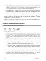
2.4. Data acquisition VI operation
The basic structure of a simple data acquisition is shown below:
The flow of Task Ids is as follows:
i.
Task Id's can only be originated by the Configure Board VI. One this has been done, you must use this Task Id
for all I/O operations on the board in question. Optional inputs to the Configure Board VI include the board type,
the base address of the board, and a logical board number. Note that this board number is used purely to identify
the board uniquely; you can use any number between 0 and 7, as long as you don't use the same number for two
boards.
ii.
The Task Id from the Configure board VI can then be used to configure the analog input, analog output and
digital I/O subsections of the board. The VIs in question are:
a) AD Channel Configure : This configures a range of A/D input channels. You can use several of these VIs in
series to configure different channels differently. You can also configure a channel in a particular way,
perform an input function, and then reconfigure the channel for a different function.
b) DA Channel Configure : This configures a range of D/A output channels. You can use several of these VIs
in series to configure different channels differently. You can also configure a channel in a particular way,
perform an output function, and then reconfigure the channel for a different function.
c) DIO Port Configure : This configures a range of digital I/O ports. You can use several of these VIs in series
to configure different ports differently. You can also configure a port in a particular way, perform a digital
I/O function, and then reconfigure the port for a different function.
iii.
10
Once a Task Id has been originated by the Configure Board VI, and processed by one of the subsystem
configuration VIs, you can perform any of the analog input, analog output or digital I/O functions.
Using the VIs
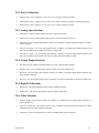
2.5. Multiple execution paths
When data acquisition functions are connected in series as shown above, then the functions execute serially; a specific
function cannot execute until the previous function has completed. Sometimes it can be useful to allow data acquisition
functions to execute in parallel. This can be done as follows:
Note the following:
i.
All configuration functions must be completed prior to the execution paths splitting
ii.
VIs in parallel as above may execute in any order.
iii.
If one path contains a clocked I/O operation to a particular subsystem, then no parallel path should contain any
I/O operation involving that subsystem.
iv.
Only one path in a set of parallel paths may contain a clocked I/O operation.
v.
Split execution paths can be resyncronized by the Synchronize VI.
2.6. Channel addressing
Channel addressing for the UEIDAQ LabVIEW ® drivers is done via arrays of channels . Two kinds of arrays are
supported:
i.
Integer arrays. Integer arrays are simply arrays of integer channel numbers. If you only want to select one
channel, simply create an array of only one element.
ii.
String channel arrays are identical to LabVIEW® channel arrays:
a) You can separate channel entries by placing each one in a separate array element, or
b) separate channel entries by placing them in a single array element separated by commas (e.g. 1,2,3), or
c) specify a range of channels by separating the first and last channels by a colon (e.g. 1:3), or
d) any combination of the above
2.7. Error codes
The error codes used by the UEIDAQ LabVIEW ® drivers have exactly the same meaning as for standard LabVIEW ®
VI's. Thus normal LabVIEW® error handling VIs can be used.
The error codes used are:
Using the VIs
11
0
No Error.
-61
Bad board; normally caused by an error in an earlier VI.
-69
Input parameters out of range.
-72
Operation requiring the requested subsystem is already in progress.
-10005
Multi-tasking error; usually caused by a bad device number.
-10007
Channel number out of range
-10019
Clock frequency was invalid.
-10080
Gain setting invalid
-10402
Device not found
-10403
Invalid parameters; the operation was not attempted.
-10444
Insufficient memory.
-10600
Subsystem or board has not been configured.
-10805
Hardware error; an error occurred during an I/O operation to a board.
-10840
Unknown error; probably as the result of a version conflict.
-20008
Array sizes are invalid.
-20021
Filter size must be greater than 1.
-20023
Cutoff frequencies were invalid.
2.8. Quick reference
The data acquisition VIs in the UEIDAQ library include:
2.8.1. Configuration functions
•
Configure Board : Configures a board.
•
AD Chan Config : Configures a range of analog input channels.
•
DA Chan Config : Configures a range of analog output channels.
•
DIO Port Config : Configures a range of digital I/O channels.
•
Version : Returns the version number of the UEIDAQ DLL that is installed on your system.
12
Using the VIs
2.8.2. Easy I/O functions
•
AD Easy Wave: This is a high level, easy to use, way to acquire an analog waveform.
•
AD Trig Wave: This is a high level, easy to use, way to acquire an analog waveform, with analog triggering.
•
DA Easy Wave: This is a high level, easy to use, way to output an analog waveform.
2.8.3. Analog input functions
•
AD Chan In : Acquires a single sample from each of a group of channels.
•
AD Wave In : Low level analog input function. Starts a waveform acquisition process.
•
AD Check : Low level analog input function. Checks to see whether a waveform acquisition started by AD Wave
In has completed.
•
AD Close To Integer : Low l evel analog input function. Completes a waveform input function started by AD
Wave In. The output from the function is an array of integer data.
•
AD Close To Single : Low level analog input function. Completes a waveform input function started by AD
Wave In. The output from the function is an array of single precision floating point data.
2.8.4. Analog Output functions
•
DA Chan Out: This outputs a specified voltage on a group of analog output channels.
•
DA Wave Out : Low level analog output function. Starts a waveform output process.
•
DA Check : Low level analog input function. Checks to see whether a waveform output operation started by DA
Wave Out has completed.
•
DA Close : Low level analog output function. Completes a waveform output function started by DA Wave Out.
2.8.5. Digital I/O functions
•
DIO Port In : This inputs digital data from a group of digital input ports.
•
DIO Port Out : This outputs digital data to a group of digital output ports.
2.8.6. Utility functions
•
Software Trigger : This function emulates the operation of a oscilloscope style analog trigger operation on a
buffer with data in it.
•
String To Int Chan List : This function converts a list of channels in string format to the integer array format
required by most of the data acquisition functions.
•
Synchronize : This VI synchronizes the execution of multiple paths of data acquisition.
Using the VIs
13
Chapter 3
3. Configuration functions
This chapter provides a description of the various configuration VIs used by the driver.
3.1. Configuration VI introduction
The configuration VIs are:
•
Configure Board : Configures a board.
•
AD Chan Config : Configures a range of analog input channels.
•
DA Chan Config : Configures a range of analog output channels.
•
DIO Port Config : Configures a range of digital I/O channels.
3.2. Configure board
Configure board configures the specified board.
This function is used to detect the presence of a specific board, and to configure it for operation. The output of this VI,
the Task Id, is required as an input by subsequent data acquisition operations, and serves to identify on which board the
operation is to be performed.
Base Address is the base address of the board. If this is set to -1, then the default base address for the board
type is used. If the base address is set to 0, and the type is set to auto-identify, then an address of 700 hex is
used. The value defaults to -1
Configuration VIs
15
Board number is the board's logical identifying number. This may be between 0 and 7, and may be
arbitrary chosen, as long as no two boards have the same number. It defaults to 0.
Type is the board type. This may be one of the following values
0 : Auto-identify
1 : UEI-26/UEI-30
2 : UEI-39
3 : UEI-30B or UEI-30C
4 : UEI-30D or UEI-30DS
5 : UEI-30PGL
6 : UEI-30PGH
7 : UEI-126
8 : UEI-127
9 : WIN-30D/DS
10 : WIN-30PGL and PGSL
11 : WIN-30PGH and PGSH
12 : WIN-3016D/DS
13 : WIN-3016PGL and PGSL
14 : WIN-3016PGH and PGSH
15 : UEI-14
16 : UEI-36
17 : UEI-192
18 : UEI-66
19 : UEI-64
20 : UEI-73
Note that not all board types can be auto-identified. Also remember to consult the RELEASE.TXT file on
the distribution diskette to see what boards your specific version of the UEIDAQ supports. The default
setting for this control is auto-identify.
Primary DMA is the primary DMA channel. For boards that do not support software configuration of
DMA levels, this should be set to correspond to the DMA level for which your board has been configured.
In the case of boards that do support software configuration of DMA levels, the board will be set to this
DMA level. Consult your hardware manual for a discussion of the appropriate DMA level for your
application. If this control is set to -1, the default level, a setting of 3 is used for boards that use 8-bit DMA,
and a setting of 5 for boards that use 16-bit DMA.
Secondary DMA is the secondary DMA channel for those boards that support dual-channel gap-free DMA.
For boards that do not support software configuration of DMA levels, this should be set to correspond to the
DMA level for which your board has been configured. In the case of boards that do support software
configuration of DMA levels, the board will be set to this DMA level. Consult your hardware manual for a
discussion of the appropriate DMA level for your application. If this control is set to -1, the default level, a
setting of 0 is used for boards that use 8-bit DMA, and a setting of 6 for boards that use 16-bit DMA.
16
Configuration VIs
Interrupt Level is the interrupt level (IRQ setting) for the board. For boards that do not support software
configuration of interrupt levels, this should be set to correspond to the interrupt level for which your board
has been configured. In the case of boards that do support software configuration of interrupt levels, the
board will be set to this interrupt level. Consult your hardware manual for a discussion of the appropriate
interrupt level for your application. If this control is set to -1, the default level, the interrupt level will be set
to the factory default for type of board identified, or to IRQ5 for boards that are software programmable.
Task Id is the Task Id corresponding to the board. This must be used in all subsequent subsystem
configuration VIs.
Type Out is the type of the board as actually identified by the UEIDAQ diagnostics function. If you
specified anything other than auto-identify for the input type, then this will be the same as the input type,
unless an error condition occurred.
Status contains the VI error code. Negative values indicate an error. See the section on error codes for
more information on these.
3.3. AD Chan Configure
AD channel configure configures a range of A/D input channels for range, gain and mode.
Task Id in is the Task Id corresponding to the board. This must be obtained from the Configure Board VI.
There is no default for this control.
Channel list is a list of the channels that are to be configured. To convert from a string format channel list
to the integer format required by this function, use the String To Int Chan List VI. The default setting is -1,
which selects all channels on the board.
Range indicates the analog voltage range for the channels. Note that most boards are limited to a single
range that applies to all channels. For such boards, if more than one range is requested, the most recent
request is used. Note also that if the board that you are using does not support software range selection, then
you must ensure that the range input corresponds to the range that your board is actually configured for. If
these do not correspond, then voltage readings from subsequent functions will be incorrect. The default
setting for this control is -5 to +5V. Range may be one of the following values:
0 : -5 to +5V
1 : 0 to +5V
2 : -10 to +10V
3 : 0 to +10V
4 : -2.5 to +2.5V
Configuration VIs
17
5 : 0 to +2.5V
Mode indicates the input mode. Default setting is single ended. Possible values are:
0 : Single ended
1 : Differential
Gain list is a list of the gains that the various channels in the channel list are to be set to, for example 10 or
1000. If this list is shorter than the channel list, it wraps round. If it is longer than the channel list, extra
values are ignored. Default setting is 1. Note that these values are the actual gain values, NOT gain codes as
used by UEIDAQ.
Task Id out is the Task Id corresponding to the board. This must be used in all subsequent analog input
subsystem VIs.
Status contains the VI error code. Negative values indicate an error. See the section on error codes for
more information on these.
3.4. DA Chan Configure
DA channel configure configures a range of D/A output channels for range and mode.
Task Id in is the Task Id corresponding to the board. This must be obtained from the Configure Board VI.
There is no default for this control.
Channel list is a list of the channels that are to be configured. To convert from a string format channel list
to the integer format required by this function, use the String To Int Chan List VI. The default setting is -1,
which selects all channels on the board.
Range indicates the analog voltage range for the channels to be configured. If the board that you are using
does not support software range selection, then you must ensure that the range input corresponds to the
range that your board is actually configured for. If these do not correspond, then voltage outputs from
subsequent functions will be incorrect. The default setting for this control is -5 to +5V. Range may be one
of the following values:
0 : -5 to +5V
1 : 0 to +5V
2 : -10 to +10V
3 : 0 to +10V
4 : -2.5 to +2.5V
18
Configuration VIs
5 : 0 to +2.5V
Mode indicates the output mode. This is currently unused, and should be left unconnected.
Task Id out is the Task Id corresponding to the board. This must be used in all subsequent analog output
subsystem VIs.
Status contains the VI error code. Negative values indicate an error. See the section on error codes for
more information on these.
3.5. DIO Port Configure
DIO port configure configures a range of DIO output ports for direction and mode.
Task Id in is the Task Id corresponding to the board. This must be obtained from the Configure Board VI.
There is no default for this control.
Channel list is a list of the ports that are to be configured. To convert from a string format channel list to
the integer format required by this function, use the String To Int Chan List VI. The default setting is -1,
which selects all ports on the board.
Latch Mode indicates the input latch mode. This is currently unused, and should be left unconnected.
Direction indicates whether the port is to be an input or an output. This is ignored for board with fixed DIO
port configuration. The default value is for the ports to be inputs. Values are:
0 : Output
1 : Input
Task Id out is the Task Id corresponding to the board. This must be used in all subsequent digital I/O
subsystem VIs.
Status contains the VI error code. Negative values indicate an error. See the section on error codes for
more information on these.
3.6. Version
Configuration VIs
19
Returns the version number of the UEIDAQ DLL that is installed on your system.
Version returns the UEIDAQ version number, encoded with the minor version number in the lower 8 bits,
and the major version number in the next highest 8 bits.
20
Configuration VIs
Chapter 4
4. Easy I/O functions
This chapter provides a description of the various Easy I/O VIs used by the driver.
4.1. Easy I/O VI introduction
Easy I/O VIs are simplified versions of the more advanced, but also more complex, low level VIs. As they are
constructed out of low level VIs, you can use these VIs as to learn how to use the low level VIs, or as starting points for
your own VIs. The Easy I/O VIs are:
•
AD Easy Wave: This is a high level, easy to use, way to acquire an analog waveform.
•
AD Trig Wave: This is a high level, easy to use, way to acquire an analog waveform, with analog triggering.
•
DA Easy Wave: This is a high level, easy to use, way to output an analog waveform.
4.2. AD Easy Wave
AD Easy Wave performs timed multi-channel input operations. You can specify which channels to sample, how often to
sample them, and how many samples to obtain. The output data is scaled to the range and gain of the selected channels.
This function uses internal triggering and clocks.
Task Id in is the Task Id corresponding to the board. This must be obtained from the AD Chan Configure
VI. There is no default for this control.
Channel list is a list of the channels that are to be sampled. This is in string format. For a discussion of this
format, see the section on channel addressing. The default setting is channel 0.
Easy VIs
21
Samples per channel is the number of samples to be taken for each channel in the channel list. the default
is 1024.
Sampling rate in is the rate at which each channel individually will be sampled. Board throughput is the
product of the sampling rate and the number of channels. Note that regardless of whether block mode is
selected or not, this rate is still the rate at which each channel is sampled. The default sampling rate is 1
kHz.
Block mode selects whether samples are taken in normal or block mode, for those boards that support this.
Because of the way that the sampling rate is interpreted by the VI, this setting has no effect on the rate at
which channels are sampled. It does have an effect on the phase of the samples: If block mode is true, then
the phase shift between samples taken on the same scan through the channel list will be as small as the
board can make it. For simultaneous sampling boards, this will be 0, and for other boards equal to
1/(Maximum throughput). If block mode is false, then samples taken on the same scan through the channel
list will be evenly spread through the sampling interval. For more information on block mode sampling, see
your hardware manual.
Data Out is a two dimensional array of output data. Its size is the product of the number of channels and
the number of samples. It is scaled to the range and gain selected by the AD Chan Configure VI that
preceded the AD Easy Wave operation.
Sampling Period Out is the actual period between successive conversions on the same input channel. Note
that this may not be exactly what would be expected from the Sampling Rate In control, as data acquisition
boards can generally select sampling periods in finite sized steps.
Task Id out is the Task Id corresponding to the board. This must be used in all subsequent I/O operations.
Status contains the VI error code. Negative values indicate an error. See the section on error codes for
more information on these.
4.3. AD Trig Wave
AD Trig Wave performs timed multi-channel input operations with analog triggering. You can specify which channels to
sample, how often to sample them, and how many samples to obtain. The output data is scaled to the range and gain of
the selected channels. This function uses internal triggering and clocks. Analog triggering is simulated by acquiring three
times more data that is required, looking for a trigger condition, and then discarding data prior to the trigger condition.
Depending on the Mode setting, the VI can either wait for a valid trigger, or return immediately whether or not a valid
trigger was found. Note that because this VI simulates analog triggering, it is possible that it will miss single shot events.
Thus it should be used only on repetitive waveforms.
22
Easy VIs
Task Id in is the Task Id corresponding to the board. This must be obtained from the AD Chan Configure
VI. There is no default for this control.
Channel list is a list of the channels that are to be sampled. This is in string format. For a discussion of this
format, see the section on channel addressing. The default setting is channel 0.
Samples per channel is the number of samples to be taken for each channel in the channel list. the default
is 1024.
Sampling rate in is the rate at which each channel individually will be sampled. Board throughput is the
product of the sampling rate and the number of channels. Note that regardless of whether block mode is
selected or not, this rate is still the rate at which each channel is sampled. The default sampling rate is 1
kHz.
Block mode selects whether samples are taken in normal or block mode, for those boards that support this.
Because of the way that the sampling rate is interpreted by the VI, this setting has no effect on the rate at
which channels are sampled. It does have an effect on the phase of the samples: If block mode is true, then
the phase shift between samples taken on the same scan through the channel list will be as small as the
board can make it. For simultaneous sampling boards, this will be 0, and for other boards equal to
1/(Maximum throughput). If block mode is false, then samples taken on the same scan through the channel
list will be evenly spread through the sampling interval. For more information on block mode sampling, see
your hardware manual.
Position sets the amount of pre-trigger data required.
Slope is the slope of the trigger event to be searched for. If this is true, then a positive slope is searched for,
and if it is false, a negative slope
Mode is the trigger mode. If this is false, then a AD Trig wave will always output data, regardless of
whether a valid trigger condition was encountered. This is equivalent of “Auto” triggering on an
oscilloscope; data will always be displayed. If Mode is true, the VI will not return until a valid trigger
condition has been encountered. The default setting is false.
Level sets the level at which the trigger condition will occur.
Data Out is a two dimensional array of output data. Its size is the product of the number of channels and
the number of samples. It is scaled to the range and gain selected by the AD Chan Configure VI that
preceded the AD Easy Wave operation.
Sampling Period Out is the actual period between successive conversions on the same input channel. Note
that this may not be exactly what would be expected from the Sampling Rate In control, as data acquisition
boards can generally select sampling periods in finite sized steps.
Task Id out is the Task Id corresponding to the board. This must be used in all subsequent I/O operations.
Status contains the VI error code. Negative values indicate an error. See the section on error codes for
more information on these.
Easy VIs
23
Position sets the amount of pre-trigger data required. Effectively, the Software Trigger VI doesn’t start
searching for data in the first <Position> samples in the input buffer.
Data In is a the data to be searched. Note that this is a one dimensional array.
Slope is the slope of the trigger event to be searched for. If this is true, then a positive slope is searched for,
and if it is false, a negative slope
Mode is the trigger mode. If this is false, then a found will always return true, regardless of whether a valid
trigger was found. This is equivalent of “Auto” triggering on an oscilloscope; data will always be displayed.
If it is true, found will only return true if a valid trigger condition was found
Level sets the level at which the trigger condition will occur.
Trigger Point represents the offset into the data buffer at which the specified trigger condition occurred. If
no trigger occurred, and . Mode was false, then this will return 0.
Found is set if either a valid trigger condition occurred, or mode was false.
4.4. DA Easy Wave
DA Easy Wave performs timed multi-channel output operations. You can specify which output channels to update, how
often to update them, and how many times the output data is to be repeated to obtain. The output data is scaled to the
range and gain of the selected channels. This function uses internal triggering and clocks.
Task Id in is the Task Id corresponding to the board. This must be obtained from the DA Chan Configure
VI. There is no default for this control.
Channel list is a list of the channels that are to be used for waveform generation. This is in string format.
For a discussion of this format, see the section on channel addressing. The default setting is channel 0.
Sampling rate in is the rate at which each D/A will be updated.
Data In is a two dimensional array of output data. Its size is the product of the number of channels and the
number of samples. DA Easy Wave assumes that the smallest dimension corresponds to the number of D/A
channels to be updated.
Cycles is the number of times that the input data will be repeated. A setting of 0 selects continuous updates;
however use of this mode is not recommended as there will be no way of stopping the VI. If continuous
output is required, the low level VIs should be used individually, as shown in the DA Wave example VI.
24
Easy VIs
Sampling Period Out is the actual period between successive conversions on the same input channel. Note
that this may not be exactly what would be expected from the Sampling Rate In control, as data acquisition
boards can generally select sampling periods in finite sized steps.
Task Id out is the Task Id corresponding to the board. This must be used in all subsequent I/O operations.
Status contains the VI error code. Negative values indicate an error. See the section on error codes for
more information on these.
Easy VIs
25
Chapter 5
5. Analog input functions
This chapter provides a description of the various analog input VIs used by the driver.
5.1. Analog input VI introduction
The analog input VIs are:
•
AD Chan In : Acquires a single sample from each of a group of channels.
•
AD Wave In : Low level analog input function. Starts a waveform acquisition process.
•
AD Check : Low level analog input function. Checks to see whether a waveform acquisition started by AD Wave
In has completed.
•
AD Close To Integer : Low level analog input function. Completes a waveform input function started by AD
Wave In. The output from the function is an array of integer data.
•
AD Close To Single : Low level analog input function. Completes a waveform input function started by AD
Wave In. The output from the function is an array of single precision floating point data.
5.2. AD Chan In
AD Chan In obtains a single sample from each of the specified channels. The output data is available either as raw
integer data, or as floating point data scaled to the range and gain of the selected channels.
Task Id in is the Task Id corresponding to the board. This must be obtained from the AD Chan Configure
VI. There is no default for this control.
Channel list is a list of the channels that are to be measured. To convert from a string format channel list to
the integer format required by this function, use the String To Int Chan List VI. The default setting is 0.
Analog In VIs
27
Integer Out is a one dimensional array of integer format output data. For information on data encoding,
consult your hardware reference manual.
Float Out is a one dimensional array of output data. It is scaled to the range and gain selected by the AD
Chan Configure VI that preceded the AD Chan In operation. Data is in the same order as the Channel list
array.
Task Id out is the Task Id corresponding to the board.
Status contains the VI error code. Negative values indicate an error. See the section on error codes for
more information on these.
5.3. AD Wave In
AD Wave In starts a timed multi-channel input operation. You can specify which channels to sample, how often to
sample them, and how many samples to obtain. You check for completion of the operation by using the AD Check VI,
and complete the operation by using the AD Close VI.
Warning : The buffer descriptor output from the AD Wave In function must always find its way to a corresponding AD
Close VI, regardless of any error conditions which may occur. If this is not done, any memory used by the AD Wave In
function may become permanently lost.
Task Id in is the Task Id corresponding to the board. This must be obtained from the AD Chan Configure
VI. There is no default for this control.
Channel list is a list of the channels that are to be measured. To convert from a string format channel list to
the integer format required by this function, use the String To Int Chan List VI. The default setting is 0.
Samples per channel is the number of samples to be taken for each channel in the channel list. the default
is 1024.
Sampling rate in is the rate at which each samples will be taken. Note that this rate is NOT the same as the
rate used by the AD Easy Wave function; actual sampling rate depends on the block size. The default
sampling rate is 1 kHz.
Block size sets the size of blocks, for those boards that support block mode operations. Setting a block size
of 1 is the same as setting a block size of zero. If block size is 0 or 1, then a single sample is taken on each
clock pulse. In this case board throughput is equal to the sampling rate. If block size is greater than 1, then a
number of samples equal to the block size are taken on each clock pulse (for boards that support
simultaneous sampling, simultaneously). In this case the board throughput is equal to the product of the
28
Analog In VIs
sampling rate and the block size. For more information on block mode sampling, see your hardware manual.
Default block size is 0.
Trigger mode selects the board's trigger mode, for those boards that support software programmable
trigger modes. The default setting is internal. The following values are supported:
0 : Internal
1 : External
Clock Mode selects whether the A/D clock is derived from the internal clock, or is supplied externally, for
those boards that support software programmable clock sources. The default setting is internal. The
following values are supported:
0 : Internal
1 : External
Sampling Period Out is the actual time between clock pulses. Note that may not be exactly what would be
expected from the Sampling Rate In control, as data acquisition boards can generally select sampling
periods only in finite sized steps.
Buffer descriptor provides information to the AD Check and AD Close VIs. You must not modify this
information in any way.
Task Id out is the Task Id corresponding to the board. This must be used in all subsequent I/O operations.
Status contains the VI error code. Negative values indicate an error. See the section on error codes for
more information on these.
5.4. AD Check
AD Check checks for the completion of an waveform input operation started by the AD Wave In VI.
Task Id in is the Task Id corresponding to the board. This must be obtained from the AD Wave In VI.
There is no default for this control.
Buffer descriptor provides status information from the AD Wave In VI. You must not modify this
information in any way. The Buffer descriptor output should be wired to the AD Close function
Task Id out is the Task Id corresponding to the board. This must be used in all subsequent I/O operations.
Wait is true if the function has not yet completed, and false if it has.
Analog In VIs
29
Status contains the VI error code. Negative values indicate an error. See the section on error codes for
more information on these.
5.5. AD Close to Integer
AD Close to Integer closes a data acquisition operation started by AD Wave In. The output of this function is an array of
16-bit integers. For a version of this function that outputs scaled floating point values, see the AD Close To Single VI.
Task Id in is the Task Id corresponding to the board. This must be obtained from the AD Wave In VI or
AD Check VI. There is no default for this control.
Buffer descriptor provides status information from the AD Wave In and AD Check VIs. You must not
modify this information in any way.
Task Id out is the Task Id corresponding to the board. This must be used in all subsequent I/O operations.
Integer Results is a two dimensional array of output data. Its size is the product of the number of channels
and the number of samples. For information on data encoding, consult your hardware reference manual.
Status contains the VI error code. Negative values indicate an error. See the section on error codes for
more information on these.
5.6. AD Close to Single
AD Close to Single closes a data acquisition operation started by AD Wave In. The output of this function is an array of
floating point values. The size of this array will be twice that of an array of integer values. For a version of this function
that outputs integer values, see the AD Close To Integer VI.
Task Id in is the Task Id corresponding to the board. This must be obtained from the AD Wave In VI or
AD Check VI. There is no default for this control.
Buffer descriptor provides status information from the AD Wave In and AD Check VIs. You must not
modify this information in any way.
Task Id out is the Task Id corresponding to the board. This must be used in all subsequent I/O operations.
30
Analog In VIs
Float Results is a two dimensional array of output data. Its size is the product of the number of channels
and the number of samples. It is scaled to the range and gain selected by the AD Chan Configure VI that
preceded the AD Wave in operation.
Status contains the VI error code. Negative values indicate an error. See the section on error codes for
more information on these.
Analog In VIs
31
Chapter 6
6. Analog Output functions
This chapter provides a description of the various analog output VIs used by the driver.
6.1. Analog output VI introduction
The analog output VIs are:
•
DA Chan Out: This outputs a specified voltage on a group of analog output channels.
•
DA Wave Out : Low level analog output function. Starts a waveform output process.
•
DA Check : Low level analog input function. Checks to see whether a waveform output operation started by DA
Wave Out has completed.
•
DA Close : Low level analog output function. Completes a waveform output function started by DA Wave Out.
6.2. DA Chan Out
DA Chan Out writes a single value to each of the specified channels. The values can be either raw integer data, or
floating point data scaled to the range of the selected channels.
Task Id in is the Task Id corresponding to the board. This must be obtained from the DA Chan Configure
VI. There is no default for this control.
Channel list is a list of the channels to which data is to be written. To convert from a string format channel
list to the integer format required by this function, use the String To Int Chan List VI. The default setting is
0.
Analog Out VIs
33
Integer In is a one dimensional array of integer format data to be written to the analog outputs. For
information on data encoding, consult your hardware reference manual. Note that either integer OR floating
point data, not both, must be supplied to this VI
Float In is a one dimensional array of output data. It must be scaled to the range and gain selected by the
DA Chan Configure VI that preceded the DA Chan Out operation. Data is in the same order as the Channel
list array. Values that are out of range will be limited to the selected channel's output range.
Task Id out is the Task Id corresponding to the board.
Status contains the VI error code. Negative values indicate an error. See the section on error codes for
more information on these.
6.3. DA Wave Out
DA Wave Out DA Wave Out starts a timed multi-channel output operation. You can specify which channels to send data
to, how often to update them, and how many times to repeat the data. You check for completion of the operation by
using the DA Check VI, and complete the operation by using the DA Close VI.
Warning : The buffer descriptor output from the DA Wave Out function must always find its way to a corresponding
DA Close VI, regardless of any error conditions which may occur. If this is not done, any memory used by the DA Wave
Out function may become permanently lost.
Task Id in is the Task Id corresponding to the board. This must be obtained from the DA Chan Configure
VI. There is no default for this control.
Channel list is a list of the channels to which data is to be written. To convert from a string format channel
list to the integer format required by this function, use the String To Int Chan List VI. The default setting is
0.
Sampling rate in is the rate at which the outputs will be updated. The default sampling rate is 1 kHz.
Cycles sets the number of times that the input data will be sent to the D/A converters. Setting a value of 0
repeats the data continuously until the DA Close Vi is called.
Trigger mode selects the board's trigger mode, for those boards that support software programmable
trigger modes. The default setting is internal. The following values are supported:
0 : Internal
1 : External
34
Analog Out VIs
Clock Mode selects whether the D/A clock is derived from the internal clock, or is supplied externally, for
those boards that support software programmable clock sources. The default setting is internal. The
following values are supported:
1 : Internal
0 : External
Data in is the waveform data to be sent to the D/A converters. This is scaled voltage data.
Sampling Period Out is the actual time between clock pulses. Note that may not be exactly what would be
expected from the Sampling Rate In control, as data acquisition boards can generally select sampling
periods only in finite sized steps.
Buffer descriptor provides information to the DA Check and DA Close VIs. You must not modify this
information in any way.
Task Id out is the Task Id corresponding to the board. This must be used in all subsequent I/O operations.
Status contains the VI error code. Negative values indicate an error. See the section on error codes for
more information on these.
6.4. DA Check
DA Check checks for the completion of an waveform output operation started by the DA Wave Out VI.
Task Id in is the Task Id corresponding to the board. This must be obtained from the DA Wave Out VI.
There is no default for this control.
Buffer descriptor provides status information from the DA Wave Out VI. You must not modify this
information in any way. The Buffer descriptor output should be wired to the DA Close function
Task Id out is the Task Id corresponding to the board. This must be used in all subsequent I/O operations.
Wait is true if the function has not yet completed, and false if it has.
Status contains the VI error code. Negative values indicate an error. See the section on error codes for
more information on these.
Analog Out VIs
35
6.5. DA Close
DA Close closes a data acquisition operation started by DA Wave Out.
Task Id in is the Task Id corresponding to the board. This must be obtained from the DA Wave Out VI or
DA Check VI. There is no default for this control.
Buffer descriptor provides status information from the DA Wave Out and DA Check VIs. You must not
modify this information in any way.
Task Id out is the Task Id corresponding to the board. This must be used in all subsequent I/O operations.
Status contains the VI error code. Negative values indicate an error. See the section on error codes for
more information on these.
36
Analog Out VIs
Chapter 7
7. Digital I/O functions
This chapter provides a description of the various digital I/O VIs used by the driver.
7.1. Digital I/O VI introduction
The digital I/O VIs are:
•
DIO Port In : This inputs digital data from a group of digital input ports.
•
DIO Port Out : This outputs digital data to a group of digital output ports.
7.2. DIO Port In
DIO Port In obtains a single sample from each of the specified digital input ports.
Task Id in is the Task Id corresponding to the board. This must be obtained from the DIO Port Configure
VI. There is no default for this control.
Port list is a list of the ports that are to be sampled. To convert from a string format channel list to the
integer format required by this function, use the String To Int Chan List VI. The default setting is 0.
Data is a one dimensional array of integer format output data. Data is in the same order as is the port list.
For information on data encoding, consult your hardware reference manual.
Task Id out is the Task Id corresponding to the board.
Status contains the VI error code. Negative values indicate an error. See the section on error codes for
more information on these.
Digital I/O VIs
37
7.3. DIO Port Out
DIO Port Out writes a single value to each of the specified DIO ports.
Task Id in is the Task Id corresponding to the board. This must be obtained from the DIO Port Configure
VI. There is no default for this control.
Port list is a list of the ports to which data is to be written. To convert from a string format channel list to
the integer format required by this function, use the String To Int Chan List VI. The default setting is 0.
Data is a one dimensional array of integer format data to be written. Each integer value represents the data
for a single port. Data is in the same order as is the port list. For information on data encoding, consult your
hardware reference manual.
Task Id out is the Task Id corresponding to the board.
Status contains the VI error code. Negative values indicate an error. See the section on error codes for
more information on these.
38
Digital I/O VIs
Chapter 8
8. Utility functions
This chapter provides a description of the various utility VIs provided by the driver.
8.1. Utility VI introduction
The utility VIs are:
•
Software Trigger : This function emulates the operation of a oscilloscope style analog trigger operation on a
buffer with data in it.
•
String To Int Chan List : This function converts a list of channels in string format to the integer array format
required by most of the data acquisition functions.
•
Synchronize : This function synchronizes the execution of multiple paths of data acquisition.
8.2. Software Trigger
Software Trigger Software Trigger looks for a trigger condition in an array of data, and return information on whether
the condition was found, and the position at which the condition was found. This allows an analog trigger to be emulated
in software. For a example of how to use this VI, study the AD Trig Wave VI.
Position sets the amount of pre-trigger data required. Effectively, the Software Trigger VI doesn’t start
searching for data in the first <Position> samples in the input buffer.
Data In is a the data to be searched. Note that this is a one dimensional array.
Slope is the slope of the trigger event to be searched for. If this is true, then a positive slope is searched for,
and if it is false, a negative slope.
Utility VIs
39
Mode is the trigger mode. If this is false, then found will always return true, regardless of whether a valid
trigger was found. This is equivalent of “Auto” triggering on an oscilloscope; data will always be displayed.
If it is true, found will only return true if a valid trigger condition was found.
Level sets the level at which the trigger condition will occur.
Trigger Point represents the offset into the data buffer at which the specified trigger condition occurred. If
no trigger occurred, and Mode was false, then this will return 0.
Found is set if either a valid trigger condition occurred, or mode was false.
8.3. String To Int Chan List
String To Int Chan List converts a channel list in the form of a string array to a channel list formatted as an integer array.
String Channel Array is a list of the channels. This is in string format. For a discussion of this format, see
the section on channel addressing. The default setting is channel 0.
Integer Channel Array is a list of the channels formatted as integers.
8.4. Synchronize
Synchronize synchronizes multiple paths of execution. For more information see the section on multiple execution paths.
Task Id 1 In is the Task Id corresponding to the first execution path to be synchronized. If this control is
left unconnected it is ignored.
Task Id 2 In is the Task Id corresponding to the second execution path to be synchronized. If this control is
left unconnected it is ignored.
Task Id 3 In is the Task Id corresponding to the third execution path to be synchronized. If this control is
left unconnected it is ignored.
Task Id 4 In is the Task Id corresponding to the fourth execution path to be synchronized. If this control is
left unconnected it is ignored.
40
Utility VIs
Task Id 1 Out is the Task Id corresponding to the first execution path to be synchronized. Once this task
ID emerges, all input paths to the VI have completed.
Task Id 2 Out is the Task Id corresponding to the second execution path to be synchronized. Once this task
ID emerges, all input paths to the VI have completed.
Task Id 3 Out is the Task Id corresponding to the third execution path to be synchronized. Once this task
ID emerges, all input paths to the VI have completed.
Task Id 4 Out is the Task Id corresponding to the fourth execution path to be synchronized. Once this task
ID emerges, all input paths to the VI have completed.
Utility VIs
41
Chapter 9
9. Signal processing VIs
The various signal processing VIs perform various analysis functions such as frequency domain transforms on acquired
data.
9.1. Signal processing introduction
The available signal processing functions are:
•
FFT : performs a Fast Fourier Transform.
•
Inverse FFT : performs an inverse Fast Fourier Transform.
•
Hilbert transform : performs a Fast Hilbert Transform.
•
Inverse Hilbert transform : performs an inverse Fast Hilbert Transform.
•
Chirp-Z transform : Performs a Chirp-Z transform.
•
Convolution : computes the convolution of two signals.
•
Zero pad : Pads a waveform with zeros such that the waveform length is a power of two.
9.2. FFT
The FFT function (UEI FFT) computes the FFT of an input sequence. If no imaginary input is connected, the VI
performs an FFT on only the real-valued part. Note that this function is a "pure" FFT; if the length of the inputs are not
powers of two, then they are truncated to the next lowest power of 2. If this is undesirable, then the Zero Pad VI can be
used to pad out the sequence to the next higher power of 2.
Signal Processing VIs
43
Re{X} is the real valued part of the input sequence.
Im{X} is the imaginary valued part of the input sequence.
Re FFT{X} is the real valued part of the output sequence.
Im FFT{X} is the imaginary valued part of the output sequence.
Error contains the VI error code. Negative values indicate an error. See the section on error codes for more
information on these.
9.3. Inverse FFT
The Inverse FFT function (UEI Inverse FFT) computes the inverse FFT of an input sequence. If no imaginary input is
connected, the VI performs the function on only the real-valued part. Note that this function is a "pure" inverse FFT; if
the length of the inputs are not powers of two, then they are truncated to the next lowest power of 2. If this is
undesirable, then the Zero Pad VI can be used to pad out the sequence to the next higher power of 2.
Re{X} is the real valued part of the input sequence.
Im{X} is the imaginary valued part of the input sequence.
Re IFFT{X} is the real valued part of the output sequence.
Im IFFT{X} is the imaginary valued part of the output sequence.
Error contains the VI error code. Negative values indicate an error. See the section on error codes for more
information on these.
9.4. Hilbert transform
The Hilbert transform function (UEI Hilbert) computes the fast Hilbert transform of an input sequence. Note that if the
length of the input is not a power of two, then it is truncated to the next lowest power of 2. If this is undesirable, then the
Zero Pad VI can be used to pad out the sequence to the next higher power of 2.
{X} is the input sequence.
44
Signal Processing VIs
HLB{X} is the output sequence.
Error contains the VI error code. Negative values indicate an error. See the section on error codes for more
information on these.
9.5. Inverse Hilbert transform
The Inverse Hilbert transform function (UEI Inverse Hilbert) computes the inverse fast Hilbert transform of an input
sequence. Note that if the length of the input is not a power of two, then it is truncated to the next lowest power of 2. If
this is undesirable, then the Zero Pad VI can be used to pad out the sequence to the next higher power of 2.
{X} is the input sequence.
IHLB{X} is the output sequence.
Error contains the VI error code. Negative values indicate an error. See the section on error codes for more
information on these.
9.6. Chirp-Z
The Chirp-Z function (UEI Chirp Z) computes the Chirp-Z transform of an input sequence. If no imaginary input is
connected, the VI performs the transform on only the real-valued part. The Chirp-Z transform is similar to the FFT, but
where the FFT always converts to the frequency domain over a fixed range of frequencies, the Chirp-Z allows the range
of frequencies to be selected. Technically, the FFT algorithm evaluates over the unit circle in the z-plane, while the
Chirp-Z evaluates over a user definable portion of the unit circle. The Chirp-Z VI provided here is not a full Chirp-Z
transform; a full transform has parameters which allow the evaluation to take place not only over a portion of the unit
circle as in this case, but over a arbitrary spiral in the z-plane.
Note that if the length of the inputs are not powers of two, then they are truncated to the next lowest power of 2. If this is
undesirable, then the Zero Pad VI can be used to pad out the sequence to the next higher power of 2.
Re{X} is the real valued part of the input sequence.
Im{X} is the imaginary valued part of the input sequence. If no imaginary input is connected, the VI
performs the transform on only the real-valued part.
Signal Processing VIs
45
Start Frequency is the frequency at which the transform is to be started, scaled such that 1 is equivalent to
half the sequence's sampling frequency. The default value for this control is 0.
End Frequency is the frequency at which the transform is to be ended, scaled such that 1 is equivalent to
half the sequence's sampling frequency. The default value for this control is 1.
Re FFT{X} is the real valued part of the output sequence.
Im FFT{X} is the imaginary valued part of the output sequence.
Error contains the VI error code. Negative values indicate an error. See the section on error codes for more
information on these.
9.7. Convolution
The convolution VI (UEI Convolution) computes the convolution
convolution.
of X and Y. Note that this is NOT a circular
X is the first sequence to be convolved.
Y is the second sequence to be convolved.
X*Y is the convolution of the two sequences.
Error contains the VI error code. Negative values indicate an error. See the section on error codes for more
information on these.
9.8. Zero pad
Zero pad (UEI Zero Pad) pads the input sequence with trailing zeros, such that the size of the output array is a power of
2. This is used when you want to use one of the transform VI's that require the length of their input data to be a power of
two, on data that is not a power of two.
X is the data to be padded.
Padded {X} is the padded data.
46
Signal Processing VIs
Error contains the VI error code. Negative values indicate an error. See the section on error codes for more
information on these.
Signal Processing VIs
47
Chapter 10
10. Window VIs
Window operations are used both for filter design and spectrum analysis.
10.1. Windows VI introduction
The following windows are available:
•
Hamming window.
•
Hanning window.
•
Blackman-Harris window.
When a continuous waveform is sampled, the start and end of the sampling operation unavoidably introduce
discontinuities. These discontinuities almost inevitably translate into the frequency domain as unwanted spectral leakage .
This leakage can be reduced by applying a smoothing window. However, application of such a window has an
undesirable side effect; the width of frequency components that actually are present is increased, making more difficult
to precisely identify the presence or absence of signals. In general, there is a tradeoff between the degree to which a
particular window suppresses spectral leakage, and the extent to which it broadens spectral components. The analysis
library provides an assortment of windows offering different combinations of characteristics:
The other major application for smoothing windows is in the design of FIR filters . Analytic expressions are available for
the tap weights for most simple FIR filters. These expressions are infinite in duration, and thus for practical applications,
Windows VIs
49
must be truncated. This results in a problem very similar to that discussed above, but known as Gibb's phenomenon.
Once again, smoothing windows can reduce this effect.
Note that all of these window functions are normalized for operation as smoothing functions for use in spectrum analysis
systems. They are scaled to compensate for power loss. When used for filter design, they must be scaled back to unity
gain. See the FIR window coefficients VI for an example of how to do this.
10.2. Hamming window
This function applies a Hamming window to the input sequence.
Note : This window is normalized to preserve the average power in the input waveform. It must be scaled for use in filter
design.
X is the data to be windowed.
Ham {X} is the windowed data.
Error contains the VI error code. Negative values indicate an error. See the section on error codes for more
information on these.
10.3. Hanning window
This function applies a Hanning window to the input sequence.
Note : This window is normalized to preserve the average power in the input waveform. It must be scaled for use in filter
design.
X is the data to be windowed.
Han {X} is the windowed data.
Error contains the VI error code. Negative values indicate an error. See the section on error codes for more
information on these.
50
Windows VIs
10.4. Blackman-Harris window
This function applies a Blackman-Harris window to the input sequence. Note that this is the "4-term minimum" window,
which provides over 92 dB of sidelobe rejection, not the more common 3-term version. This high sidelobe rejection
makes this window very useful for data acquisition functions, as it reduces the level of spectral leakage to below the
noise floor of even a 16-bit converter.
Note : This window is normalized to preserve the average power in the input waveform. It must be scaled for use in filter
design.
X is the data to be windowed.
Blkh {X} is the windowed data.
Error contains the VI error code. Negative values indicate an error. See the section on error codes for more
information on these.
Windows VIs
51
Chapter 11
11. Spectrum analysis VIs
Spectrum analysis VIs are used to estimate the spectral content of a sampled signal.
11.1. Spectrum analysis introduction
The following functions are available:
•
Power spectrum : This VI computes the 2-sided power spectrum of a waveform.
•
Linear spectrum : This VI computes the 2-sided voltage spectrum of a waveform.
•
Power Chirp-Z spectrum : Thi s VI computes the power spectrum of a waveform over a specified frequency
interval.
•
Linear Chirp-Z spectrum : This VI computes the voltage spectrum of a waveform over a specified frequency
interval.
•
Spectrum Analysis : This VI computes the single sided spectrum of a waveform in a format suitable for display in
a graph. Output can be in voltage, power or dB's, and a smoothing window can be specified.
•
Chirp-Z Spectrum Analysis : This VI computes the spectrum of a waveform over a specified frequency interval,
in a format suitable for display in a graph. Output can be in voltage, power or dB's, and a smoothing window can
be specified.
It should be noted that all of these functions are only capable of estimating the spectral content of a signal. For example,
what were single spectral components in a continuous signal may be spread into multiple frequency bins by the sampling
process. This is the so called "scalloping " loss or "picket fence effect ". Effects of this loss can vary from nothing to a
window dependent maximum which can be from 4 dB (no window) to 0.83 dB (4-term Blackman-Harris). For more
information, see for example "Digital Signal Processing", A.V.Oppenheim, R.W. Schafer, Prentice-Hall, 1975 and "On
the Use of Windows for Harmonic Analysis with the Discrete Fourier Transform", F.J. Harris, Proc. IEEE, Vol 66, No.
1, January 1978.
Spectrum Analysis VIs
53
11.2. Power Spectrum
Power Spectrum (UEI Power Spectrum) computes the two sided power spectrum of an input sequence. If the input
sequence is expressed in volts, then the output sequence represents power into 1 Ohm. The size of the input sequence
must be a power of 2. If it is not, the sequence will be truncated. If this is undesirable, then the Zero Pad VI can be used
to pad out the sequence to the next higher power of 2.
X is the input sequence.
Power Spectrum is the power spectrum.
Error contains the VI error code. Negative values indicate an error. See the section on error codes for more
information on these.
11.3. Linear Spectrum
Linear Spectrum (UEI Linear Spectrum) computes the two sided linear spectrum of an input sequence. If the input
sequence is expressed in volts, then the output sequence represents volts. This is calculated by taking the square root of
the power sequence above. The size of the input sequence must be a power of 2. If it is not, the sequence will be
truncated. If this is undesirable, then the Zero Pad VI can be used to pad out the sequence to the next higher power of 2.
X is the input sequence.
Linear Spectrum is the linear spectrum.
Error contains the VI error code. Negative values indicate an error. See the section on error codes for more
information on these.
11.4. Power Chirp-Z Spectrum
Power Chirp-Z Spectrum (UEI Power Chirp-Z Spectrum) computes the power spectrum of an input sequence. The
Chirp-Z transform is similar to the FFT process used by the Power Spectrum VI, but where the FFT always converts to
54
Spectrum Analysis VIs
the frequency domain over a fixed range of frequencies, the Chirp-Z allows the range of frequencies to be selected.
Technically, the FFT algorithm evaluates over the unit circle in the z-plane, while the Chirp-Z evaluates over a user
definable portion of the unit circle. If the input sequence is expressed in volts, then the output sequence represents power
into 1 Ohm. The size of the input sequence must be a power of 2. If it is not, the sequence will be truncated. If this is
undesirable, then the Zero Pad VI can be used to pad out the sequence to the next higher power of 2.
X is the input sequence.
Start is the frequency at which the transform is to be started, scaled such that 1 is equivalent to half the
sequence's sampling frequency. The default value for this control is 0.
End is the frequency at which the transform is to be ended, scaled such that 1 is equivalent to half the
sequence's sampling frequency. The default value for this control is 1.
Power Spectrum is the power spectrum.
Error contains the VI error code. Negative values indicate an error. See the section on error codes for more
information on these.
11.5. Linear Chirp-Z Spectrum
Linear Chirp-Z Spectrum (UEI Linear Chirp-Z Spectrum) computes the linear spectrum of an input sequence. The
Chirp-Z transform is similar to the FFT process used by the Power Spectrum VI, but where the FFT always converts to
the frequency domain over a fixed range of frequencies, the Chirp-Z allows the range of frequencies to be selected.
Technically, the FFT algorithm evaluates over the unit circle in the z-plane, while the Chirp-Z evaluates over a user
definable portion of the unit circle. If the input sequence is expressed in volts, then the output sequence represents volts.
This is calculated by taking the square root of the power sequence above. The size of the input sequence must be a
power of 2. If it is not, the sequence will be truncated. If this is undesirable, then the Zero Pad VI can be used to pad out
the sequence to the next higher power of 2.
X is the input sequence.
Start is the frequency at which the transform is to be started, scaled such that 1 is equivalent to half the
sequence's sampling frequency. The default value for this is 0.
End is the frequency at which the transform is to be ended, scaled such that 1 is equivalent to half the
sequence's sampling frequency. The default value for this is 1.
Linear Spectrum is the linear spectrum.
Error contains the VI error code. Negative values indicate an error. See the section on error codes for more
information on these.
Spectrum Analysis VIs
55
11.6. Spectrum Analysis
The spectrum analysis VI computes the single sided spectrum of a waveform in a format suitable for display in a graph.
Output can be in voltage, power or dB's, and a smoothing window can be specified. This VI processes the 2 sided output
from the Power Spectrum VI into a format suitable for display. It correctly accounts for the effect of this operation on
the DC component of the input sequence.
Sampling Period is the sampling period of the input sequence, as for example provided by the AD easy
Wave function.
Window Select selects an optional smoothing window. Possible selections are:
0 : No window
1 : Hanning window
2 : Hamming window
3 : Blackman-Harris window
Data In is the input sequence.
dB/Linear selects the output format. Possible selections are:
0 : dB
1 : Power; Watts into 1 Ohm
2 : Voltage
Frequency Inc is the frequency increment between successive values in the output data. This can be used
as an input to a waveform graph.
Data Out is the spectrum output.
11.7. Chirp-Z Spectrum Analysis
56
Spectrum Analysis VIs
The Chirp-Z spectrum analysis VI computes the single sided spectrum of a waveform, over a specified frequency
interval, in a format suitable for display in a graph. The Chirp-Z transform is similar to the FFT process used by the
Spectrum Analysis VI, but where the FFT always converts to the frequency domain over a fixed range of frequencies,
the Chirp-Z allows the range of frequencies to be selected. Technically, the FFT algorithm evaluates over the unit circle
in the z-plane, while the Chirp-Z evaluates over a user definable portion of the unit circle. Output can be in voltage,
power or dB's, and a smoothing window can be specified. This VI processes the 2 sided output from the Power Chirp-Z
Spectrum VI into a format suitable for display. Note that this VI does NOT correct for the effects of this operation on
the DC component of the input sequence.
Frequency Start is the frequency at which the transform is to be started, scaled such that 1 is equivalent to
half the sequence's sampling frequency. The default value for this control is 0.
Frequency End is the frequency at which the transform is to be ended, scaled such that 1 is equivalent to
half the sequence's sampling frequency. The default value for this control is 1.
Sampling Period is the sampling period of the input sequence, as for example provided by the AD easy
Wave function.
Window Select selects an optional smoothing window. Possible selections are:
0 : No window
1 : Hanning window
2 : Hamming window
3 : Blackman-Harris window
Data In is the input sequence.
dB/Linear selects the output format. Possible selections are:
0 : dB
1 : Power; Watts into 1 Ohm
2 : Voltage
Frequency Start Out is the frequency at which the output data starts, scaled to the sampling frequency.
This can be used as an input to a waveform graph.
Frequency Inc is the frequency increment between successive values in the output data. This can be used
as an input to a waveform graph.
Data Out is the spectrum output.
Spectrum Analysis VIs
57
Chapter 12
12. Filter VIs
The filter VIs are used to filter waveforms.
12.1. Filter VI introduction
The following filter VIs are available:
•
FIR coefficients : Calculates the coefficients of specified FIR (Finite Impulse Response) filter.
•
FIR window coefficients : Calculates the coefficients of specified FIR filter, using a specified smoothing window.
•
FIR Filter : Performs a FIR filtering operation on data sequence.
FIR (Finite Impulse Response) filters have several advantages over other possible digital filter realizations such as
Infinite-duration Impulse Response (IIR) filters:
i.
They are always stable,
ii.
always realizable, and
ii.
can always be designed to have linear phase.
The easiest design technique is windowed design . Although other techniques, notably the Parks-McClellan algorithm,
can lead to shorted filters, these algorithms do not always converge. In addition, the LabVIEW ® environment is not
particularly memory or processing power bound.
Briefly, the windowed design technique follows these steps:
i.
Choose a window which gives the desired stopband attenuation. Note that stopband attenuation is not the same as
the sidelobe attenuation discussed previously with respect to spectrum analysis.
ii.
Using the required transition width (the frequency width from the edge of the passband to the edge of the
stopband) from the filter specification, and the transition width of the selected window, calculate the number of
taps required in the filter.
iii.
Use the analytic filter design formulas to obtain an expression giving the tap weights (or coefficients) for the
filter.
Filter VIs
59
iv.
Window the resulting tap weights with the selected window.
For an algorithm and numerical values for this technique, see the Filter Estimate example VI, and for a simple tutorial on
it, see "Digital Signal Processing Laboratory", V.K. Ingle, J.G. Proakis, Analog Devices/Prentice Hall, 1991.
12.2. FIR coefficients
The FIR coefficients (UEI FIR Coefficients) VI computes the tap weights for a FIR filter, based on FIR design formulas.
This VI always designs linear phase filters, both for odd and even filter lengths.
Type selects the type of filter. Possible selections are:
0 : Lowpass
1 : Highpass
2 : Bandpass
3 : Bandstop
The default value is 0.
fs is the sampling frequency of the input sequence to the FIR filter. The default value is 1.
fl is the low cutoff frequency. This must be between 0 and fs/2. The default value is 0.12.
fh is the high cutoff frequency. This must be between fl and fs/2. This is ignored for lowpass and highpass
filters. The default value is 0.45
Taps is the number of taps in the filter. This is the size of the output array.
FIR Coefficients are the filter weights.
Status contains the VI error code. Negative values indicate an error. See the section on error codes for
more information on these.
60
Filter VIs
12.3. FIR Windowed coefficients
The FIR Windowed coefficients (UEI FIR Window Coefficients) VI computes the tap weights for a FIR filter, based on
FIR design formulas and a selected window. This VI always designs linear phase filters, both for odd and even filter
lengths.
Type selects the type of filter. Possible selections are:
0 : Lowpass
1 : Highpass
2 : Bandpass
3 : Bandstop
The default value is 0.
fs is the sampling frequency of the input sequence to the FIR filter. The default value is 1.
fl is the low cutoff frequency. This must be between 0 and fs/2. The default value is 0.12.
fh is the high cutoff frequency. This must be between fl and fs/2. This is ignored for lowpass and highpass
filters. The default value is 0.45
Window selects an optional smoothing window. Possible selections are:
0 : No window
1 : Hanning window
2 : Hamming window
3 : Blackman-Harris window
Taps is the number of taps in the filter. This is the size of the output array.
FIR Coefficients are the filter weights.
Status contains the VI error code. Negative values indicate an error. See the section on error codes for
more information on these.
Filter VIs
61
12.4. FIR Filter
The FIR Filter (UEI FIR Filter) VI implements a FIR filter. It computes the tap weights for a FIR filter, based on FIR
design formulas and a selected window, then filters the input sequence with this filter. This VI always designs linear
phase filters, both for odd and even filter lengths.
Filter Type selects the type of filter. Possible selections are:
0 : Lowpass
1 : Highpass
2 : Bandpass
3 : Bandstop
The default value is 0.
Sampling Freq: fs is the sampling frequency of the input sequence to the FIR filter. The default value is 1.
Low cutoff Freq: fl is the low cutoff frequency. This must be between 0 and fs/2. The default value is 0.12.
High cutoff freq: fh is the high cutoff frequency. This must be between fl and fs/2. This is ignored for
lowpass and highpass filters. The default value is 0.45
Window selects an optional smoothing window. Possible selections are:
0 : No window
1 : Hanning window
2 : Hamming window
3 : Blackman-Harris window
Taps is the number of taps in the filter. This is the size of the output array.
X is the input sequence.
Filtered Data is the filtered sequence.
Error contains the VI error code. Negative values indicate an error. See the section on error codes for more
information on these.
62
Filter VIs
Filter VIs
63
Index
AD Chan In, 23
Data analysis, 9
AD channel configure, 10, 17
Digital I/O, 10
AD Check, 25
Digital I/O boards, 4
AD Close to Integer, 26
Digital I/O VIs, 31
AD Easy Wave, 21
DIO port configure, 11, 19
AD Wave In, 24
DIO Port In, 31
Analog input, 9
DIO Port Out, 32
Analog output, 10
Directories, 7
Analog output boards, 4
DLL, 5, 7
Analog output VIs, 29
DMA, 2, 10
Analysis, 9
Driver, 6
Arrays of channels, 11
Dynamic Linked Library, 5
Blackman-Harris window, 43
Easy I/O, 21
Channel addressing, 11
Enhanced mode, 4, 7
Chirp-Z, 37, 47, 49
Error codes, 12
Chirp-Z spectrum analysis, 49
FFT, 35
Configuration, 5, 10
Filter VIs, 51
Configure Board, 10
FIR coefficients, 52
Configure board, 15
FIR Filter, 54
Convolution, 38
FIR filter, 51
DA Chan Out, 29
FIR filters, 41
DA channel configure, 10, 18
FIR Windowed coefficients, 53
Data acquisition, 9
Fourier Transform, 35
Data acquisition boards, 9
Hamming window, 42
Index
65
66
Hanning window, 42
Subsystem, 9
Hilbert transform, 36
Synchronize, 34
Installation, 6
SYSTEM.INI, 8
Interrupt, 2
Task Id, 10
Interrupts, 10
UEI-126, 3
Inverse FFT, 36
UEI-127, 3
Inverse Hilbert transform, 37
UEI-14, 4
Linear Chirp-Z Spectrum, 47
UEI-192, 4
Linear Spectrum, 46
UEI-26, 1
Multi-tasking, 10
UEI-30, 1
Name, 9
UEI-30B, 2
Noise floor, 43
UEI-30C, 2
Old series, 1
UEI-30D, 2
Parallel, 11
UEI-30DS, 2, 5
Picket fence effect, 45
UEI-30DS/4, 2, 5
Power Chirp-Z Spectrum, 47
UEI-30PG, 3
Power Spectrum, 46
UEI-36, 4
Premium series, 2, 3
UEI-39, 2
Ring 0, 7
UEI-66, 4
Scalloping, 45
UEI-66A, 4
Sidelobe rejection, 43
UEIDAQ, 5, 6
Signal processing VIs, 35
UEIDAQV.386, 7
Spectral content, 45
Utility VIs, 33
Spectral leakage, 41
Version, 20
Spectrum analysis, 48
Virtual device driver, 5, 7
Spectrum analysis VIs, 45
Vxd, 5, 7, 8
Standard mode, 7
Window VIs, 41
String To Int Chan List, 33
Windowed design, 51
Index
Windows, 4, 7
Zero pad, 38
Index
67