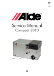
1
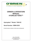
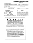
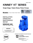
Inflatable Pipe Plugs
Trelleborg Ridderkerk BV
Table of Contents
- Inflatable Pipe Plugs / Flow Stoppers : OLS Page 2 and 3
- Pipe Plug with Flexible Bypass: Flex ODS
Page 4 and 5
- Inflatable Bypass Plugs : ODS
Page 6 and 7
- Megaplug ODS
Page 8 and 9
- Flexibele Long Packer: Flex-LP
Page 10
- Accessories
Page 11
- User Manual for Inflatable pipe stopper
Page 12
- Users Manual Megaplug ODS
Page 13 and 14
- Example Factory Test Report
Page 15
- Chemical resistance list Chloroprene- and Nitrile plugs
Page 16
Policy quality, environment, safety and health
The policy of Trelleborg Ridderkerk BV is to design, produce and deliver rubber products which are in
accordance with the customers’ requests, needs and expectations. The starting point of our policy is the
Trelleborg Group policy statement ‘Code of Conduct’ on our website www.trelleborg.com.
During the development of products and processes the environment, safety and health are integral to the
process. Trelleborg Ridderkerk BV is using an integrated management system which complies to international
standards such as ISO 9001, ISO 14001 and SCC**.
Quality and Safety
Because quality and safety are one of the most important aspects in working with pipe plugs
we test every plug before delivery at one and a half times the working pressure.
This test is performed in the largest pipe diameter for that type.
For the strength of the construction we work with a safety margin of at least 3 times the
indicated operating pressure on the plug.
The plugs are suitable for testing with air and water according to Euro Norm NEN-EN 1610:
Construction and Testing of Drains and Sewers.
We do have the right to change, when necessary, the information in this publication without any notice upfront.
For the most up to date information: do contact your supplier. All rights reserved. Nothing from this edition may
be copied, saved in an atomized data file, or be published, in any format, without previous notice.
1
Inflatable
Pipe Plugs /
Flow Stoppers:
The Inflatable pipe plugs, (Dutch abbreviation OLS) are flow stoppers
for temporary close off a range of pipe-diameters. The OLS flow stoppers/plugs are very suitable for use in sewage-systems with inspections,
repairs, cleaning but also for pressure testing the drain system according
to Euro Norm NEN-EN.
The OLS flow stoppers from the range 70-150 mm are build up with high
quality aramide (Kevlar) reinforced layers of neoprene rubber. The plugs
are multi-size flow stoppers, this means that with each flow stopper you
can close off a range of pipe-diameters. The flow stoppers are easy to
install, and as even more important easy and quick removed because of
the relative small diameter and light weight.
OLS
Type: OLS
Range
Max. workin pressure
Dmin
Length
Weight
40/70*
65/100*
70/150*
100/200-S*
100/200*
150/300*
200/400*
300/600*
500/1000*
500/1200
mm
40-70
65-100
70-150
100-200
100-200
150-300
200-400
300-600
500-1000
500-1200
inch
1,5-2,7
2,5-4
2,7-6
4-8
4-8
6-12
8-16
12-24
20-40
20-48
Bar
1,5
1,5
1,5
3,0
3,0
3,0
3,0
3,0
3,0
3,0
PSI
22
22
22
44
44
44
44
44
44
44
mm
35
60
65
95
95
135
180
290
460
440
inch
1,4
2,3
2,6
3,7
3,7
5,3
7,1
11,4
18,1
17,3
mm
160
100
310
250
500
500
500
700
1000
1650
inch
6,3
4
12,2
9,8
19,7
19,7
19,7
27,6
39,4
65,0
kg
0,35
0,2
0,55
1,1
2
2,3
4
9
20
52
LBS
0,8
0,44
1,2
2,4
4,4
5,1
8,8
19,8
44,1
114,6
*also available in Nitrile.
2
Type: OLS
40/70
Max. working pressure
Pipe diameter
65/100
70/150
100/200 S
100/200
150/300
200/400
300/600
500/1000
500/1200
Bar
PSI
Bar
PSI
Bar
PSI
Bar
PSI
Bar
PSI
Bar
PSI
Bar
PSI
Bar
PSI
Bar
PSI
Bar
PSI
1,5
22
1,5
22
1,5
22
3,0
44
3,0
44
3,0
44
3,0
44
3,0
44
3,0
44
3,0
44
Bar
PSI
Bar
PSI
Bar
PSI
Bar
PSI
Bar
PSI
Bar
PSI
Bar
PSI
Bar
PSI
Bar
PSI
Max. backpressure
mm
Inch
Bar
PSI
40
1,5
0,9
13
0,7
10
70
2,7
100
4
1,1
13
0,9
13
0,8
12
0,8
12
150
6
2
29
2
29
0,7
10
1,3
19
1,6
180
23
2
29
7
0,7
10
1,4
20
1,7
23
200
8
0,5
7
1,3
19
1,5
21
2
29
300
12
1,1
13
1,8
25
2
29
400
16
1,2
13
1,8
26
500
20
1,6
23
2
29
1,9
28
600
24
0,9
13
1,9
28
1,9
28
700
27
1,8
26
1,8
26
800
32
1,7
23
1,8
26
900
35
1,1
13
1,7
25
1000
40
0,5
6
1,7
25
1200
48
0,8
12
• Above mentioned values are directions in clean and round concrete pipes.
• Maximum backpressure for air testing according to NEN-EN 1610: 200 mbar in all pipe diameters!
• Maximum backpressure for water testing according to NEN-EN 1610: 500 mbar in all pipe diameters!
3
Flex ODS:
Pipe Plug with
Flexible Bypass
Type: Flex ODS
Range
Backpressure
The Flex-ODS, is a pipe plug with a flexible bypass hose trough the stopper and with a diameter of 1”, 2” or 4”, depending on the size plug.
The Flex-ODS plugs are suited to create a diversion or bypass, when
working in the pipeline. These plugs are also perfectly suitable for testing
with air or water of a pipeline according to Euro Norm NEN-EN-1610:
Construction and Testing of drains and sewers.
The Flex-ODS is just like the OLS flow stopper build from high quality
aramide (Kevlar) reinforced layers of rubber. Standard the plugs have no
Storz coupling mounted, but can also be delivered with a Storz coupling,
stainless steel threaded connection of 1”, 2” or 4” BSP or NPT.
100/200
200/400
300/600
500/1000
500/1200
mm
100-200
200-400
300-600
500-1000
500-1200
inch
4-8
8-16
12-24
20-40
20-48
2,0
Bar
2,0
2,0
2,0
2,0
PSI
29
29
29
29
29
Dmin
mm
95
180
290
440
440
inch
3,7
7,1
11,4
17,3
17,3
Length
mm
500
500
700
1350
1650
inch
19,7
19,7
27,6
53,1
65,0
Weight
kg
LBS
Optional connection
3
8
17
52
60
6,6
17,6
37,5
114,6
132,3
1” Storz-25D
2" Storz-52C
2" Storz-52C
2” Storz-52C
4” Storz-110A
*also available in Nitrile.
** Optional Storz-coupling
4
Type: Flex ODS
100/200
Max. working pressure
Pipe diameter
200/400
300/600
500/1000
500/1200
Bar
PSI
Bar
PSI
Bar
PSI
Bar
PSI
Bar
PSI
2,0
29
2,0
29
2,0
29
2,0
29
2,0
29
Bar
PSI
Bar
PSI
Bar
PSI
Bar
PSI
Max. back pressure
mm
Inch
Bar
PSI
100
4
1,3
19
150
6
1
14
200
8
0,7
10
1,3
19
300
12
1,1
16
1,3
19
400
16
0,7
10
1,2
17
500
20
1
14
1,3
19
1,3
19
600
24
0,6
9
1,2
17
1,2
17
700
27
1,1
16
1,1
16
800
32
1,1
16
1,1
16
900
35
1
14
1,1
16
1000
40
0,6
9
1
14
1200
48
0,5
7
• Above mentioned values are directions in clean and round concrete pipes.
• Maximum backpressure for air testing according to NEN-EN 1610: 200 mbar in all pipe diameters!
• Maximum backpressure for water testing according to NEN-EN 1610: 500 mbar in all pipe diameters!
5
ODS:
The Inflatable Bypass Stoppers, abbreviated ODS in Dutch, are pipe plugs
with one or more bypass-possibilities depending on size of the plug. The
ODS plug consists of a steel core supplied with
a reinforced inflatable rubber sleeve. Being inflated the sleeve clamps
around the steel core and it sets, fixates itself to the wall of the pipe.
Pipe Plug with
Bypass mounted
on pipe
The ODS plug is specially suited for testing with water. The strong sleeve
and steel core make higher operating pressures, compare to Flex-ODS,
possible and therefore excellent for rough work conditions.
The steel core can be used to stamp or strut. Suitable for testing with
air and water according to Euro Norm NEN-EN-1610: Construction and
testing of drains and sewers.
The rubber sleeve from the ODS plug is build from high quality aramide
(Kevlar) reinforced layers of rubber, and can be replaced in case of damage.
Type: ODS
Max. working pressure
Dmin
Length
Weight
100/200
200/400
300/600
500/1000
inch
4-8
8-16
12-24
20-40
3,0
Bar
3,0
3,0
3,0
PSI
44
44
44
44
mm
95
195
290
490
inch
3,7
7,7
11,4
19,3
mm
360
430
520
1010
inch
14,2
16,9
20,5
39,8
kg
LBS
Connection
4
10
23
90
8,8
22,0
50,7
198,4
2” Storz-52 C
1” Geka
1” Geka
1” Geka
1” Storz-25 D
3” Storz-75 B
2” Storz-52 C
4” Storz-110 A
6
Type: ODS
100/200
Max. working pressure
Pipe diameter
200/400
300/600
500/1000
Bar
PSI
Bar
PSI
Bar
PSI
Bar
PSI
3,0
44
3,0
44
3,0
44
3,0
44
Bar
PSI
Bar
PSI
Bar
PSI
Max. back pressure
mm
inch
Bar
PSI
100
4
1
14
150
6
0,8
12
200
8
0,7
10
1
14
300
12
0,9
13
1
14
400
16
0,7
10
0,9
13
500
20
0,8
12
1
14
600
24
0,5
7
0,9
13
700
27
0,9
13
800
32
0,9
13
900
35
0,8
12
1000
40
0,7
10
• Above mentioned values are directions in clean and round concrete pipes.
• Maximum backpressure for air testing according to NEN-EN 1610: 200 mbar in all pipe diameters!
• Maximum backpressure for water testing according to NEN-EN 1610: 500 mbar in all pipe diameters!
7
MEGAPLUGODS
The MEGAPLUG is a special inflatable plug developed for blocking the flow
in big pipe diameters larger than 1000 mm. Due to the unique construction, a big range of large diameters pipelines can be closed
off with one (1) plug which can be brought into a pipeline through the
manhole.
Safe working conditions are of the utmost importance as the power of
water can be unpredictably high in big diameter pipelines. Both the
quality of the plug as well as the working method, are of the highest
importance to create these safe working conditions. For all Megaplugs,
a full test report and user manual is being delivered with the plug. The
Megaplugs are capable to hold high backpressures because of the large
contact surface with the wall and the high operating pressure in the plug.
The Megaplug is standard equipped with a flexible bypass diameter 4”,
this for testing with air or water and/or to conduct water. For reason of
safety all Megaplugs are provided with a safety valve at the plug and a 1”
hose with a ball valve, this for a quick and safe deflating after use.
Suitable for use according to Euro Norm NEN-EN 1610.
Type: ODS Megaplug
Range
Max. working pressure
1400
1600
2000
2400
mm
500-1400
700-1600
800-2000
1200-2400
inch
20-55
27-63
32-80
48-96
1,0
Bar
1,5
1,0
1,0
PSI
22
14
14
14
Dmin
mm
490
580
780
1000
inch
19,3
22,8
30,7
39,4
Length
mm
2300
2700
3500
4300
inch
90,6
106,3
137,8
169,3
***
Weight
kg
LBS
Air connection
By-pass
95
180
235
209,4
396,8
518,1
***
1”
1”
1”
***
4” Storz-110A*
4” Storz-110A*
4” Storz-110A*
***
Bypass diameter 6” and 8” on request.
*** On request
8
Type: ODS Megaplug
Max. working pressure
Pipe diameter
1400
1600
2000
2400
Bar
PSI
Bar
PSI
Bar
PSI
Bar
PSI
1,5
22
1,0
14
1,0
14
1,0
14
Bar
PSI
Bar
PSI
Bar
PSI
Max. back pressure with water
mm
Inch
Bar
PSI
500
20
1,5
22
600
24
1,3
19
700
27
1,3
19
1
14
800
32
1,2
17
0,9
13
0,9
13
900
35
1,2
17
0,8
12
0,9
13
1000
40
1,1
16
0,8
12
0,8
12
1200
48
1,1
16
0,7
10
0,8
12
0,9
13
1400
55
0,8
12
0,7
10
0,7
10
0,9
13
1600
63
0,5
7
0,7
10
0,8
12
1800
71
0,6
9
0,7
10
2000
80
0,5
7
0,6
9
2200
87
0,5
7
2400
96
0,5
7
9
Flex-LP:
The Flexible Long Packers, called Flex-LP, are used with a re-linning-method for spot repairs and joint lengths of up to 5 meters. The packers are
used for transport and positionning of resin impregnated
re-linning base material.
Flexibele
Long
Packers
This method makes it possible to repair damaged sewerpipes, without
breaking, with new inner layer of resin impregnated base material. The
base material generally exist of fibre-reinforced 2 or 3 component epoxy
resin.
The Flex-LP Packers are build up with high reinforced layers of rubber,
with both sides aluminum ends, a mechanical coupling for air hose,
pushing rod and a hoisting eye.
Type: Flex-LP
Working length
Range
Max. working pressure
Dmin.
Product length
Weight
mm
Range
Max. working pressure
Dmin.
Product length
Weight
Range
Max. working pressure
Dmin.
Product length
Weight
70-100
70-100
70-100
70-100
70-100
1000
1500
2000
3000
4000
5000
24
39
59
79
118
157
197
mm
70-100
70-100
70-100
70-100
70-100
70-100
70-100
inch
2,7- 4
2,7- 4
2,7- 4
2,7- 4
2,7- 4
2,7- 4
2,7- 4
Bar
3,0
3,0
3,0
3,0
3,0
3,0
3,0
PSI
44
44
44
44
44
44
44
mm
46
46
46
46
46
46
46
inch
2,0
2,0
2,0
2,0
2,0
2,0
2,0
mm
800
1.250
1.700
2.200
3.200
4.200
5.200
inch
31
49
67
87
126
165
205
kg
0,6
1,0
1,5
1,8
2,4
3,0
3,6
LBS
1,3
2,2
3,2
3,9
5,2
6,6
7,9
100-150
100-150
100-150
100-150
100-150
100-150
100-150
5000
mm
600
1000
1500
2000
3000
4000
inch
24
39
59
79
118
157
197
mm
100-150
100-150
100-150
100-150
100-150
100-150
100-150
inch
4-6
4-6
4-6
4-6
4-6
4-6
4-6
Bar
2,5
2,5
2,5
2,5
2,5
2,5
2,5
PSI
36
36
36
36
36
36
36
mm
64
64
64
64
64
64
64
inch
2,5
2,5
2,5
2,5
2,5
2,5
2,5
mm
850
1250
1750
2250
3250
4250
5250
207
inch
33
49
69
89
128
167
kg
1,7
2,2
2,6
3,1
4,2
5,4
6,4
LBS
3,7
4,7
5,7
6,7
9,2
11,8
14,0
150-200
150-200
150-200
150-200
150-200
150-200
150-200
5000
Type: Flex-LP
Working length
70-100
600
inch
Type: Flex-LP
Working length
70-100
mm
600
1000
1500
2000
3000
4000
inch
24
39
59
79
118
157
197
mm
150-200
150-200
150-200
150-200
150-200
150-200
150-200
inch
6-8
6-8
6-8
6-8
6-8
6-8
6-8
Bar
2,5
2,5
2,5
2,5
2,5
2,5
2,5
PSI
36
36
36
36
36
36
36
102
mm
102
102
102
102
102
102
inch
4,0
4,0
4,0
4,0
4,0
4,0
4,0
mm
880
1280
1780
2280
3280
4280
5280
inch
34,6
50,4
70,1
89,8
129,1
168,5
207,9
kg
2,75
3,15
4
4,8
6,15
7,65
9,1
LBS
6,1
6,9
8,8
10,6
13,5
16,8
20,0
10
Accessories for the Inflatable Pipe Plugs
fig 1
fig 2
fig 3
fig 4
fig 5
fig 6
fig 7
fig 1: PU-hose for OLS 40/70 and OLS 65/100 with car tyre valve. L= 2 m.
fig 2: Rubber hose incl. quick release couplings. L= 3, 5 of 10 m.
fig 3: Rubber hose incl. quick release coupling(male), manometer, air release valve and car tyre valve.
L = 5,5 m.
fig 4: Chain(m.b.b.= 590kg) provided with shackles for handling of little plugs.
For strutting is this chain no option.
fig 5: Pressure operating valve. Equipped with pressure regulator button, pressure gauge, safety valve with air relief option and quick release couplings. The safety valve is set for safe operating pressures just above 3,0 Bar.
fig 6: Car valve adapter.
fig 7: Handpump.
11
USER MANUAL FOR INFLATABLE PIPE STOPPER (OLS)
Safety Instructions
General
•
Inflate the plug in the pipe to the maximum working pressure but never exceed the max. working pressure.
•
Never exceed the max. allowable back pressure.
•
The OLS may only be used by persons who have been properly instructed and who are familiar with the use of the OLS and
the content of the user manual.
•
When using the OLS the safety of the user and any bystanders must always be borne in mind.
•
Do not lift the OLS by the air hose, but attach a rope or chain to the lifting brace intended for the purpose.
•
The OLS is exclusively to be inserted in round pipes.
•
Fill the OLS with air which contains as little oil as possible.
•
ALWAYS connect the OLS according to the instructions listed in the complete user manual.
•
Outside of the pipe the OLS may be inflated to a maximum of 0.5 bar.
•Do not exceed maximum allowable pressure differential.
•Always connect the OLS according to instructions.
Safety measures before use
•
On each occasion, before using the OLS, inspect the surface for tears, incisions and any other damage. These can
influence the functioning of the OLS. Stoppers which are damaged or which have come into contact with chemical
substances may no longer be used. In case of doubt, contact your supplier.
•
Avoid sliding of the plug by strutting it or secure it with a suitable chain.
•
On each occasion, before using the OLS, examine the accessories with which the OLS is to be inflated. Check to ensure
that the accessories have been fitted in such a way that they will under no circumstances allow a higher pressure than the
maximal operating pressure of the type of OLS in question. The maximal operating pressure of the OLS is indicated on the
label.
•
Measure the internal diameter of the pipe within which the OLS is to be inserted. Ensure that this dimension is always within
the scope of the OLS.
•
Before inserting the OLS, clean both the exterior surface of the OLS and the interior surface of the pipe where the OLS is to
be positioned. A clean contact surface works to the advantage of a good seal as well as good life span of the OLS.
Fitting the OLS
•
Insert the full length of the OLS within the pipe before filling the OLS with air.
•
When filling the OLS inside the pipe, only fill the OLS so far that the wall is just touching. Then build up the pressure at a
safe distance.
•
The maximal operating pressure of the OLS may NEVER be exceeded. The maximal operating pressure of the OLS is
indicated on the label. Excessive pressure can cause serious accidents! There are special OLS accessories available,
specially designed to prevent the build-up of excessive pressure.
•
When using compressed-air cylinders of 200/300 bar a pressure reduction valve must always be fitted. NEVER fill the OLS
directly from a compressed-air cylinder.
*
Check the internal pressure in the OLS regularly. For safety’s sake we recommend to keep the OLS connected to air-supply
during use to prevent pressure lapse.
Connecting the OLS to the air supply system
Compressed-air system
Connect the operating valve (with safety valve) to your compressed-air system of max. 10 bar. Then use pipes to connect
the operating valve to the OLS. The OLS can now be filled.
Remark: In the case that the air in your compressed-air system contains a high level of oil, oil separators must be used.
Compressor
Connect the operating valve or tyre valve (with safety valve) to your compressor of max. 10 bar. Then use the pipes
supplied by your supplier to connect the operating valve to the OLS. The OLS can now be filled.
Compressed-air cylinder
To connect the OLS to a compressed-air cylinder of 200/300 bar, follow the instructions listed in the complete version of the
user manual.
Deflating the OLS
•
Only allow the OLS to empty once you are sure that there is nobody in the pipe system within which the OLS functioned as
a seal.
•
Empty the OLS at a safe distance in a controlled manner.
•
Empty the OLS gradually to slowly reduce the differential pressure.
•
Only allow the OLS to empty completely once the pressure differential over the OLS is minimal.
•
Do not lift the OLS by the air pipe, but attach a rope or chain to the lifting brace intended for the purpose.
•
After use, clean the OLS with soap and water and then leave the OLS to dry at room temperature.
Storing the OLS
The way in which the OLS is stored can considerably influence the life span and operative safety of the OLS.
The ISO 2230 lists the following guidelines:
•
Store at a temperature of between +15°C and +25°C.
•
Store in dry storage space.
•
Screen the OLS from direct (sun)light.
•
Screen the OLS from circulating air.
•
As far as possible ensure that the OLS is not subject to pressure while stored.
•
Avoid long-term contact with liquids during storage.
•
Avoid long-term contact with metals during storage.
•
Avoid long-term contact with other rubber items.
•
After long-term storage the OLS can be cleaned with soap and water. Once cleaned the OLS should be left to dry at room
temperature.
Repairing the OLS
In the case of damage to the OLS do not attempt to repair the OLS yourself but contact your supplier.
GEBRAUCHSANWEISUNG FÜR ROHRBLASEN.
Sicherheitsvorschriften
Allgemein
*
Befülle die Rohrblase im Rohr bis zu den zulässigen Betriebsüberdruck
aber überschreite
12
these Safety Instructions. The manufacturer is not liable for damage to persons or objects
caused by wrong use of the MEGAPLUG.
General
•
Inflate the Megaplu in the pipe to the maximum working pressure but never exceed the max. working pressure.
•
Never exceed the max. allowable back pressure.
•
The MEGAPLUG may only be used by persons who have been properly instructed and who are familiar with the use
of the MEGAPLUG and the content of the user manual.
•
When using the MEGAPLUG the safety of the user and any bystanders must always be borne in mind.
•
Do not lift the MEGAPLUG by the air hose, but attach a rope or chain to the lifting brace intended for the purpose.
•
The MEGAPLUG is exclusively to be inserted in round pipes.
•
Fill the MEGAPLUG with air which contains no oil.
•
ALWAYS connect the MEGAPLUG according to the instructions listed in the user manual.
•
Outside of the pipe the MEGAPLUG
be inflated to
a maximum
of 0.2 bar.
USER may
MANUAL
FOR
MEGAPLUG
•
Always try to strut the MEGAPLUG to avoid sliding.
Attention:
Wrong
use
Safety measures
before
useof the MEGAPLUG can cause life threatening situations! Always follow
•
On each
occasion, beforeThe
usingmanufacturer
the MEGAPLUG,is
inspect
the surface
tears, incisions
and any or
other
damage.
these
Safety
Instructions.
not liable
for for
damage
to persons
objects
can influence
functioning
of the MEGAPLUG. Stoppers which are damaged or which have come into
caused These
by wrong
use ofthethe
MEGAPLUG.
contact with chemical substances may no longer be used. In case of doubt, contact your supplier.
•
On each occasion, before using the MEGAPLUG, examine the accessories with which the MEGAPLUG is to be
General
inflated.
to ensure
thattothe
have been
fitted
suchexceed
a waythe
that
they
will under
no circumstances
•
Inflate
theCheck
Megaplu
in the pipe
the accessories
maximum working
pressure
but in
never
max.
working
pressure.
allow aexceed
higher the
pressure
than the maximal
operating pressure of the type of MEGAPLUG in question. The maximal
•
Never
max. allowable
back pressure.
operating
pressuremay
of the
MEGAPLUG
indicated
the label.
Make sure
that the and
safety
valve
clean.with the use
•
The
MEGAPLUG
only
be used by is
persons
whoonhave
been properly
instructed
who
are is
familiar
•
Measure
the internaland
diameter
of theofpipe
which the MEGAPLUG is to be inserted. Ensure that this dimension is
of
the MEGAPLUG
the content
the within
user manual.
alwaysusing
withinthe
theMEGAPLUG
scope of thethe
MEGAPLUG.
•
When
safety of the user and any bystanders must always be borne in mind.
Before
inserting
the MEGAPLUG,
clean
both
the
exterior
surface
of the
andintended
the interior
of the
••
Do
not lift
the MEGAPLUG
by the air
hose,
but
attach
a rope
or chain
toMEGAPLUG
the lifting brace
for surface
the purpose.
pipe MEGAPLUG
where the MEGAPLUG
is to
cleanpipes.
contact surface works to the advantage of a good seal as well
•
The
is exclusively
tobe
bepositioned.
inserted in A
round
as good
life span of the
•
Fill
the MEGAPLUG
withMEGAPLUG.
air which contains no oil.
•
ALWAYS connect the MEGAPLUG according to the instructions listed in the user manual.
Fitting
the
MEGAPLUG
•
Outside of the pipe the MEGAPLUG may be inflated to a maximum of 0.2 bar.
Insert
full length
of the MEGAPLUG
within the pipe before filling the MEGAPLUG with air.
••
Always
try the
to strut
the MEGAPLUG
to avoid sliding.
•
When filling the MEGAPLUG inside the pipe, only fill the MEGAPLUG so far that the wall is just touching. Then build
up the pressure
at a safe distance. Do this only from outside the pipe-system. Make sure that nobody is in the pipeSafety measures
before use
system
the filling
period!
•
On
eachduring
occasion,
before
using the MEGAPLUG, inspect the surface for tears, incisions and any other damage.
Watch:can
when
this advice
is not beeing
heavy
accidents
can
occur.
These
influence
the functioning
of thefollowed,
MEGAPLUG.
Stoppers
which
are
damaged or which have come into
•
The
maximal
operatingsubstances
pressure ofmay
the no
MEGAPLUG
may NEVER
exceeded.
Theyour
maximal
operating pressure of
contact
with chemical
longer be used.
In case be
of doubt,
contact
supplier.
the each
MEGAPLUG
is before
indicated
on the
Excessive
pressure
cause serious
accidents!
There are special
•
On
occasion,
using
the label.
MEGAPLUG,
examine
thecan
accessories
with which
the MEGAPLUG
is to be
MEGAPLUG
accessories
available,
specially designed
to fitted
prevent
the build-up
of excessive
pressure.
inflated.
Check
to ensure that
the accessories
have been
in such
a way that
they will under
no circumstances
•
Checkathe
internal
pressure
themaximal
MEGAPLUG
regularly.
For of
safety’s
sake
we recommend
to keep the
MEGAPLUG
allow
higher
pressure
thaninthe
operating
pressure
the type
of MEGAPLUG
in question.
The
maximal
connectedpressure
to air-supply
use to prevent
pressure
lapse.
operating
of theduring
MEGAPLUG
is indicated
on the
label. Make sure that the safety valve is clean.
Always use
using
to prevent
the
MEGAPLUG
from
out. Strutting
indicated
••
Measure
thestrutting
internal when
diameter
of the
the plug,
pipe within
which
the
MEGAPLUG
is tosliding
be inserted.
Ensuremethods
that this are
dimension
is
on picture
1 and
always
within
the2.scope of the MEGAPLUG.
•
Before inserting the MEGAPLUG, clean both the exterior surface of the MEGAPLUG and the interior surface of the
pipe where the MEGAPLUG is to be positioned. A clean contact surface works to the advantage of a good seal as well
as good life span of the MEGAPLUG.
Fitting the MEGAPLUG
•
Insert the full length of the MEGAPLUG within the pipe before filling the MEGAPLUG with air.
•
When filling the MEGAPLUG inside the pipe, only fill the MEGAPLUG so far that the wall is just touching. Then build
up the pressure at a safe distance. Do this only from outside the pipe-system. Make sure that nobody is in the pipesystem during the filling period!
Watch: when this advice is not beeing followed, heavy accidents can occur.
•
The maximal operating pressure of the MEGAPLUG may NEVER be exceeded. The maximal operating pressure of
the MEGAPLUG is indicated on the label. Excessive pressure can cause serious accidents! There are special
MEGAPLUG accessories available, specially designed to prevent the build-up of excessive pressure.
•
Check the internal pressure in the MEGAPLUG regularly. For safety’s sake we recommend to keep the MEGAPLUG
connected to air-supply during use to prevent pressure lapse.
•
Always use strutting when using the plug, to prevent the MEGAPLUG from sliding out. Strutting methods are indicated
on picture 1 and 2.
Picture 1: Strutting with steel chain
Picture 2: Strutting-construction.
1. Air supply hose
2. Megaplug
3. Steel chain with sufficient strength!!
1. Air supply hose
2. Megaplug
3. Strutting construction with wooden beams.
4. Connections
Page 1 of 2
Connecting the MEGAPLUG to the air supply system
•
Always fill the MEGAPLUG with an operating valve with pressure gauge that indicates the pressure within the plug.
The MEGAPLUG is supplied with a safety valve regulated on 1,5 bar. Please note that this safety valve has limited
capacity. Fill the MEGAPLUG with a supply pressure close to 1,5 bar.
•
When using compressed-air cylinders of 200/300 bar13
a pressure reduction valve must always be fitted. NEVER fill the
OLS directly from a compressed-air cylinder.
Picture 1: Strutting with steel chain
Picture 2: Strutting-construction.
1. Air supply hose
2. Megaplug
3. Steel chain with sufficient strength!!
1. Air supply hose
2. Megaplug
3. Strutting construction with wooden beams.
4. Connections
Page 1 of 2
Connecting the MEGAPLUG to the air supply system
•
Always fill the MEGAPLUG with an operating valve with pressure gauge that indicates the pressure within the plug.
The MEGAPLUG is supplied with a safety valve regulated on 1,5 bar. Please note that this safety valve has limited
capacity. Fill the MEGAPLUG with a supply pressure close to 1,5 bar.
•
When using compressed-air cylinders of 200/300 bar a pressure reduction valve must always be fitted. NEVER fill the
OLS directly from a compressed-air cylinder.
Deflating the MEGAPLUG
•
Only allow the MEGAPLUG to empty once you are sure that there is nobody in the pipe system within which the
MEGAPLUG functioned as a seal.
•
Empty the MEGAPLUG at a safe distance in a controlled manner. To speed up the deflating process the 2” Air vent
with a hose attached to it can be used.
•
Empty the MEGAPLUG gradually to slowly reduce the differential pressure.
•
Only allow the MEGAPLUG to empty completely once the pressure differential over the MEGAPLUG is minimal.
•
When performing a test with water it is absolutely necessary to reduce the backpressure by pumping away
water, before deflating the MEGAPLUG . Otherwise the plug will slide out due to the weight of the water!!!
•
After use, clean the MEGAPLUG with soap and water and then leave the MEGAPLUG to dry at room temperature.
Storing the MEGAPLUG
The way in which the MEGAPLUG is stored can considerably influence the life span and operative safety of the MEGAPLUG.
The ISO 2230 lists the following guidelines:
•
Store at a temperature of between +15°C and +25°C.
•
Store in dry storage space.
•
Screen the MEGAPLUG from direct (sun)light and circulating air.
•
As far as possible ensure that the MEGAPLUG is not subject to pressure while stored.
•
Avoid long-term contact with liquids, metals and other rubber items during storage.
•
After long-term storage the MEGAPLUG can be cleaned with soap and water. Once cleaned the MEGAPLUG should
be left to dry at room temperature.
Repairing the MEGAPLUG
In the case of damage to the MEGAPLUG do not attempt to repair the MEGAPLUG yourself but contact your supplier.
This User Manual was delivered with Megaplug no.......................... d.d. ……………….. to the
customer or end-user and explained where necessary.
Please return by fax the completed form after reading this manual, and sent it to:
Trelleborg
Bakker BV.
Fax
no.:
+31
180
433080
Trelleborg
Ridderkerk
BV.
Fax
no.:
+31
180
433080
Attn. of Sales Department
……………………………….
Supplier
…………………………………..
Customer/End-user
Page 2 of 2
14
Example Test Certificate
Fabriekscontrole-attest
Factory test report
NEN-EN 10204 2.2
Werkzeugnis
Certificat de controle
Product: Opblaasbare afsluiter
Produkt: Rohrblase
Product: Inflatable pipeplug
Produit : Bouchon gonflable tuyaux
29
2
psi
bar
i
Met dit certificaat wordt verklaard dat dit product is geproduceerd, geïnspecteerd en
getest overeenkomstig bovengenoemde specificaties.
This certificate states that the above product is produced, inspected and tested
according to above mentioned specifications.
Mit dieses Zertifikat erklären wir daß dieses Produkt ist produziert, inspiziert und geprüft
gemäß obengenannte Spezifikation.
Nous déclarons que ce produit a été contrôlé et reconnu conforme aux spécification cidessus.
TRELLEBORG
RIDDERKERK
B.V.
TRELLEBORG
BAKKER B.V.
Signature
:
Naam / name :
Name / Nom
Datum / Date:
Datum / Date
15
Chemical resistance plugs with Chloroprene and NBR cover
Resistance
Allyl chloride
CR
NBR
--
--
Acetone
--
--
Alcohol
++
++
Aluminium chloride
+/-
++
Chlorure d’aluminium
++
+/-
Aluminium nitrate
++
++
Aluminium sulphate
++
++
Anilin
--
--
Acetic acid 50%
--
--
Acetic acid 100%
--
--
Benzol(Benzene)
--
--
Petrol Ether
--
--
Bromine
--
--
Butanol
++
++
Calcium chloride
++
++
Calcium Hydroxide
++
++
Calcium Nitrate
++
++
Ether
Ethylglycol
--
--
++
++
Gasoil
+/-
++
Glycerin
++
++
Hexanol
+/-
++
Potassium carbonate
++
++
Potassium hydroxide 50%
+/-
+/-
Potassium nitrate
++
++
Potassium sulphate
++
+/-
--
--
Magnesium chloride
++
++
Hydroxyde de magnésium
++
+/-
--
+/-
Sodium carbonate
++
++
Sodium chlorite
++
++
Sodium hydroxide 25%
++
++
Sodium sulphate
Kerosene
Mineral petrol
++
+/-
Petroleum crude oil
--
+/-
Nitric acid 20%
--
--
--
--
Nitric acid 70%
Fatty acid
+/-
--
Distilled water
+/-
++
Sea water
++
++
Zinc chloride
++
++
Zinc nitrate
++
++
Zinc sulphate
++
++
Hydrochloric Acid 10%
--
+/-
Hydrochloric Acid 37%
--
+/-
+/-
+/-
Sulphuric acid 20%
-- =Not recommended
+/- =Moderate
++=Good
REMARK: 1. THE CHEMICAL RESISTANCE OF THE OLS IS ALSO DEPENDENT UPON THE CONCENTRATION, DURATION OF CONTACT AND THE
TEMPERATURE AT THE TIME USE.
2. THE CHEMICAL RESISTANCE OF THE OLS TO OTHER SUBSTANCES CAN BE ASSESSED UPON REQUEST.
3. THE CHEMICAL RESISTANCE OF THE OLS ARE VALID AT 18 DEGREES CELCIUS
16
Policy quality, environment, safety and health
The policy of Trelleborg Ridderkerk BV is to design, produce
and deliver rubber products which are in accordance with
the customers’ requests, needs and expectations.
The starting point of our policy is the Trelleborg Group
policy statement ‘Code of Conduct’ on our website
www.trelleborg.com.
During the development of products and processes the
environment, safety and health are integral to the process.
Trelleborg Ridderkerk BV is using an integrated management
system which complies to international standards such as
ISO 9001, ISO 14001 and SCC**.
Trelleborg Ridderkerk BV
Verlengde Kerkweg 15 2985 AZ Ridderkerk
P.O. Box 4007 2980 GA Ridderkerk The Netherlands.
Phone: +31 180 49 55 55 Fax: +31 180 43 30 80 Email:[email protected]
www.Trelleborg.com/infrastructure