1
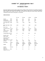
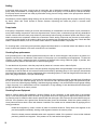
Manual 1843-1
KINNEY KT SERIES
®
™
Single Stage, Triplex Rotary Piston Pumps
Models
KT-150 KT-300 KT-500 KT-850
INSTALLATION
OPERATION
MAINTENANCE
REPAIR
MANUAL
WARNING
DO NOT OPERATE BEFORE
READING MANUAL.
ADVANCING THE STANDARDS IN VACUUM TECHNOLOGY
4840 West Kearney Street
Springfield, Missouri USA 65803-8702
Tel 417 865-8715 800 825-6937 Fax 417 865-0307
E-mail: [email protected]
06/2003
http://vacuum.tuthill.com
!
WARNING
!
CAUTION
DO NOT VALVE OR RESTRICT PUMP
DISCHARGE OPENING.
DO NOT OPERATE
WITHOUT BELT
GUARD
USE OIL MIST ELIMINATOR WHEN
OPERATING PUMP. ENSURE ADEQUATE
VENTILATION WHEN DISCHARGING
INDOORS.
REFER TO MANUAL SAFETY INSTRUCTIONS.
809762-A000
NOTICE
The above safety instruction tags were permanently affixed to
your pump prior to shipment. Do not remove, paint over or
obscure in any manner.
Failure to heed these warnings could result in serious bodily
injury to the personnel operating and maintaining this
SAFETY PRECAUTIONS FOR ROTARY PISTON PUMPS
Please read the following safety information on this page before operating your vacuum pump.
2
•
Do not operate the pump without the belt guard properly attached. Disconnect the pump motor from the electrical
supply at the main disconnect before removing the belt guard. Replace the belt guard before reconnecting the
power supply to the pump motor. Operating the pump without the belt guard properly installed exposes personnel
in the vicinity of the pump to risk from rotating drive components.
•
Do not operate the pump with oxygen-enriched gas (greater than 20% by volume) in the suction line, unless the
pump has been prepared with an inert fluid suitable for the application.
Pumping oxygen-enriched gases with mineral oil or other non-inert fluids can cause fire or explosion in the
pump, resulting in damage or serious bodily injury.
•
Take precautions to avoid prolonged or excessive exposure to oil mist or process materials emanating from the
discharge of the pump.
•
Do not allow the pump to discharge into a closed, or inadequately ventilated room. Always use a discharge oil mist
eliminator unless the pump discharge is discharged to outside atmosphere. Laws and ordinances may pertain to
your local area regarding discharge of oil mist or vapor to atmosphere. Check local laws and ordinances prior to
operation of the pump with discharge to outside atmosphere. Venting of the discharge of an oil mist eliminator to
outside atmosphere is highly recommended.
•
Do not restrict the pump discharge in any way, or place valves in the discharge line. The vacuum pump is a
compressor and will generate high pressures without stalling the motor when operated at low suction pressures.
Excessive pressure could cause damage or serious bodily injury.
•
Disconnect the pump motor from the electrical supply at the main disconnect before disassembling or servicing
the pump. Make sure pump is completely reassembled, the belt guard is properly installed, and that all fill and
drain valves are installed and closed before reconnecting the power supply. Accidental starting or operation of
the pump while maintenance is in progress could cause damage or serious bodily injury.
•
Lift pump only by the lifting lugs supplied with the pump. DO NOT lift equipment attached to pump by the pump
lifting lugs.
•
Do not touch hot surfaces on the pump. In normal operation at low pressures, surface temperatures will not
normally exceed 180° F (82° C). Prolonged operation at 200 Torr (267 mbar a) may cause surface temperatures as
high as 220° F (104° C)
TABLE OF CONTENTS
SECTION
SAFETY PRECAUTIONS AND WARNINGS
INTRODUCTION
DESCRIPTION
Specifications
Description
INSTALLATION
Installing the Vibramounts
Suction Manifolding
Proper Venting
Discharge Manifolding
Cooling Water
Filling the Pump with Oil
Vacuum Gauges
Electrical Connections
OPERATION
General
Prestart Checks
Starting The Pump
Stopping The Pump
Handling Large Quantities of Water
Gas Ballast
MAINTENANCE
General
Periodic Maintenance
Oil Contamination
Changing the Oil
Lubricating the Pump
Stalling
Pump Leaks
Checking Pump Performance
Checking Process Equipment
Discharging Valves
Shaft-Seal Assembly
V-Belt Drive
DISASSEMBLY
ASSEMBLY
2
4
5
6
7
8
9
9
9
11
12
12
12
12
13
13
13
14
14
14
14
15
15
16
16
16
16
17
19
19
20
20-21
Replacement Parts
22
Recommended Oil
22
Troubleshooting Chart
23
Parts List & Exploded Views
WARRANTY STATEMENT
24-29
30
3
INTRODUCTION
CONGRATULATIONS on your purchase of a new KINNEY® KT™ Single-Stage, Tri-plex Rotary Piston Vacuum
Pump from Tuthill Vacuum & Blower Systems. Please examine the pump for shipping damage, and if any damage is
found, report it immediately to the carrier. If the pump is to be installed at a later date make sure it is stored in a
clean, dry location and rotated regularly. Make sure covers are kept on all openings. If pump is stored outdoors be
sure to protect it from weather and corrosion.
KINNEY KT vacuum pumps are built to exacting standards and if properly installed and maintained will provide
many years of reliable service. We urge you to take time to read and follow every step of these instructions when
installing and maintaining your pump. We have tried to make these instructions as straightforward as possible. We
realize getting any new piece of equipment up and running in as little time as possible is imperative to production.
WARNING: Serious injury can result from operating or repairing this machine without first reading the service
manual and taking adequate safety precautions.
IMPORTANT: Record the pump model and serial numbers in the OPERATING DATA form below. You will save
time and expense by including this reference identification on any replacement part orders, or if you require service
or application assistance.
OPERATING DATA
It is to the user’s advantage to have the requested data filled in below and available in the event a problem
should develop in the blower or the system. This information is also helpful when ordering spare parts.
Model No. __________________________________
V-Belt Size ______________
Length _____________
Serial No. __________________________________
(Recorded from nameplate on unit)
Type of Lubrication:
_____________________________
Startup Date ________________________________
________________________
Pump RPM ________________________________
Operating Vacuum ____________________________
Pump Sheave Diameter ______________________
Any other special accessories supplied or in use:
Motor Sheave Diameter _______________________
Motor RPM _______________
NOTES:
4
HP ______________
___________________________________________
KINNEY® KT™ SERIES MANUAL 1843-1
© 2003, Tuthill Corporation
INTRODUCTION
This manual applies to Kinney Vacuum models KT-150, KT-300, KT-500 and KT-850. You should be thoroughly
familiar with these instructions before attempting to install, operate or repair this unit. Consult Tuthill Vacuum &
Blower Systems when problems arise that cannot be resolved after reading this manual. Always include pump
nameplate information when ordering parts or components.
SPECIFICATIONS
KT-150
KT-300
KT-500
KT-850
150
255
300
510
490
840
780
1325
Pump Speed (rpm) RPM
1055
870
721
581
Motor speed at 50 RPM
Hz
1,500
1,500
1,500
1,500
Motor speed at 60 RPM
Hz
1,800
1,800
1,800
1,800
Motor Power
7.5
15
30
40
Oil Capacity (total/ US gal.
refill)
Liters
6/5
23/19
10/8.5
38/32
15/12.5
57/47
28/25
106/95
Cooling water at
60° F (16° C)
1/4
1.5/6
2.5/9
3.5/13
Cooling Water Inlet Inch
NPT
1/4”
3/8”
3/8”
3/8”
Suction, 150 lb.
ANSI Flanged
3
4
6
8
Discharge, 150 lb.
ANSI Flanged
2
3
4
5
Height w/o oil mist Inches
eliminator
mm
43
1092
51
1295
63
1600
71
1803
Floor Space
Inches
mm
24x26
609x660
27x34
686x864
34x38
864x965
38x49
965x1245
Weight
Lbs
Kg
800
363
1,525
692
2,625
1,191
4,175
1,894
Ultimate
Pressure
Microns
10
10
10
10
71
72
73
75
Free Air
Displacement
CFM
m³/h
HP
Gpm
L/min
Noise Level
dBA
(Typical at 10 Torr)
5
Description
The KT-Series pumps covered herein have an oil circulating pump to provide adequate lubrication at all pressures
including atmosphere. The vacuum pump has three cams and pistons pumping in parallel, driven by a common
shaft. The cams are positioned on the shaft so as to dynamically balance moving parts. This balancing technique
applied to the Rotary Piston Principle was developed by Tuthill Vacuum & Blower Systems and virtually eliminated
vibration.
Figure 1. shows a cross section of the pump with the pistons being driven by the cams and revolving within the
cylinder.
Gas is drawn into the pump through a common inlet, channeled to the three piston slides and into the space behind
the pistons as they rotate. The gas ahead of the pistons is compressed and forced out the discharge valves. As the
gas is forced through the pump, sealing oil is mixed with the discharged gas and the discharged mixture is
channeled into the separator, which is located in the reservoir, and there the gas is separated from the oil. Sealing
and lubricating oil is provided by the oil pump which is mounted on the non-drive ahead and driven by direct
coupling to the vacuum pump drive shaft. The oil pump provides forced feed oil circulation at all operating pressures
including atmosphere.
All models have a channeled drive shaft with an opening at each cam to distribute oil through the pump.
Oil is taken from the reservoir at a point some distance above the reservoir bottom. This provides an area for
impurities to collect for draining.
Key to Figure 1.
1. Air/Oil Separator
2. Oil Level
3. Connection for optional
temperature switch
4. Connection for optional temperature gauge
5. Connection for “scum” take-off
6. Pump Inlet
7. Slide Pin
8. Water cooling jacket
9. (Far Side) Cooling Jacket drain 1 of 2
10. Mounting Pads
11. Discharge Valve
12. Gas Ballast Valve
13. Oil Drain
14. Piston Slide
15. Shaft
16. Piston
17. Cam
18. Connection for optional heater
19. Cooling jacket drain 2 of 2
Figure 1. Cross Section of KT Series Vacuum Pump
6
INSTALLATION
General
Installing the Vibramounts
KT pumps are supplied with vibramounts (vibrasprings on the KT-850) which enable them to run quietly and
vibration free. The pump can be operated on any floor which will support its weight. The pump must be installed on
the vibramounts and flexible connectors fitted in suction, discharge, water and electrical connections. It is not
necessary to bolt the pump to the floor.
If the studs are not already installed into the vibramounts, thread the short end into the top of the mount (smaller
diameter) up to the spacer portion of the stud.
The vibramount attachment holes are the four open threaded holes in the flanged edges of the cylinder, in line with
the bottom plate/cylinder bolts, just in from each corner of the pump.
DO NOT USE THE FOUR UNTHREADED HOLES WHICH ARE USED FOR SHIPMENT ONLY.
With the pump lifted off the ground, thread the vibramounts with studs into the vibramount attachment holes until
contact is made between the top of the vibramount and the cylinder bottom plate, and the foot location is parallel to
the pump shaft.
Care must be taken to set the pump down squarely on the mounts when installing the pump in operating position.
Key to Figure 2.
1. Vacuum Gauge
2. Isolation Valve
3. Air Vent Valve
4. Shut Off Valve
5. Pump Suction Flange
6. To System
7. Right angle flexible connector
8. Trap drain
Figure 2. Detailed Manifold Arrangement
7
Key to Figure 3.
1. Oil Mist Eliminator
2. Oil Return Line
3. Gas Ballast Assembly
(standard arrangement)
Figure 3. Oil Return to the Gas Ballast Valve
Suction Manifolding
Inlet manifolding should be sized and designed with four objectives in mind:
A.
B.
C.
D.
To avoid gas flow restrictions.
To prevent pump fluids from entering the process chamber.
To protect the pump from the ingestion of particulate matter.
To allow proper venting of the pump and suction manifold.
Under the normal conditions, the diameter of the manifolding should not be less than the diameter of the pump
connection and the pipe length should be kept to a minimum.
Oil may splash from inside the pump through the suction port so the suction line must be designed to prevent oil
from collecting there and draining back to the system or process. See Figure 2 for recommended arrangements as
a guide for fabricating inlet manifolding.
A flexible connection should be installed in the suction manifold to provide freedom for vibramounts. The vacuum
piping must be well aligned with the pump connections so as not to place a strain on the piping.
Provisions for gauge installation and any other drilling in the piping must be made prior to piping installation,
otherwise, drilling particles entering the piping could be entrained into the pump. A vacuum isolation valve should be
installed adjacent to the suction port to be used for leak checking, shutting down the system, or blanking off the
pump.
Before connecting the suction manifolding, distribute 4 quarts of oil over the three slide pins. This will necessitate
reaching through the suction port with a container and pouring oil directly onto the slide pins. Then rotate the pump
by hand a minimum of two revolutions to distribute the oil throughout the pump interior.
During the initial operation and as long thereafter as necessary, a fine mesh screen should be installed across the
inlet connection to prevent abrasive or solid particles left in the line from being sucked into the pump. This screen
can be removed when particles no longer accumulate. If particles continue to accumulate, a filter should be installed
in the line.
8
Proper Venting
The Vacuum pump must be properly vented to ensure all oil is removed from the pumping chamber before the
pump is turned off. Also, the suction line must be properly vented to ensure oil does not migrate into the process
chamber.
Recommended vent valve sizes:
KT-150
KT-300
KT-500
KT-850
.75 inch
1.0 inch
1.5 inches
2.0 inches
The vent valve must be open for at least 10 seconds before the pump is turned off to remove all oil from the pumping
chamber.
Discharge Manifolding
Discharge manifolding should be sized and designed to prevent the following:
A. Return of oil mist condensate to the pump
B. Oil loss
C. Oil mist in the discharged gas.
Under the normal conditions, the diameter of the manifolding should not be less than the diameter of the pump
connection and pipe length should be kept to a minimum.
The installation of a Kinney oil mist eliminator on the discharge is recommended for all applications, (as shown in
Figure 4). Oil which collects in the eliminator should be returned to the pump. The optional oil return kit will drain
allow oil to back into the separator housing when the pump is operating at low pressure or when the pump is
stopped. If the pump is to operate continuously, or normal operating pressure is between 10 torr (13 mbar) and 150
torr (200 mbar), the oil return should be connected to the gas ballast as shown in Figure 3. Over 150 torr (200 mbar)
the oil return should be connected to the pump inlet.
It may be necessary to pipe the pump exhaust fumes away from the pump area, such as outdoors. If this is done,
the piping must be arranged to prevent line condensation from returning to the pump. A flexible connector should be
fitted in the discharge line to provide freedom for the vibramounts.
Cooling Water
The cylinder cooling water jacket is shipped dry, with the drain plugs removed. They are tied to the pump in a small
cloth bag. Replace the plugs in the positions shown in Figure 1 and fill the water jacket before starting the pump.
If an optional water flow modulating valve (Water Miser) is fitted, the cylinder may take 20 minutes or more to fill. The
delay can be avoided by lifting the spring to open the valve. For installation of the valve see Figure 6.
Failure to ensure that the cooling water jacket is filled before starting the pump will result in localized over-heating of
the pump and cause extensive damage.
For installations requiring starting at ambient temperatures lower than 60°F (16°C), electric heaters should be
installed in the water jacket. (See Figure 5.)
9
Key to Figure 4.
1. Discharge connection
2. Relief Valve
3. Top cover gasket
4. Element
5. Oil Drain Connection
6. Optional oil drain line
kit
7. Oil Return connection
Figure 4. Oil Mist Eliminator
DO NOT ALLOW THE COOLING WATER TO FREEZE IN THE PUMP.
Freezing of the cooling water jacket usually results in extensive damage to the pump cylinder which cannot be repaired.
Connect a water supply line with “on-off” valve to the water inlet, and an open drain to the water outlet. The inlet
line should have a flow regulating valve. If the water supply unreliable, it is advisable to install a flow switch to stop
the pump or signal when the flow is interrupted. Normally the cooling water will be off when the pump is not running.
A water pressure relief valve is fitted in the water jacket. This relief valve is set to open at 50 PSIG (3.5 bar).
Standard cooling water rates are for up to 80°F (26°C) supply temperature and operation within the design continuous operating pressure range of .1 to 100 Torr (.13-130 mbar a). Sustained operation above 100 torr (130
mbar) and/or long pump downs generally require larger cooling water flow rate and/or external oil heat exchanger.
Larger cooling water rate increases cooling efficiency reduces heat dissipation to room and keeps oil cooler
Key to Figure 5.
1. Heaters
2. For 460 volts
3. For 430 volts
4. Switch
5. Input (fuse protected)
6. Temperature Gauge
7. Optional temperature switch
8. Install (1) heater into ¾ NPT tap far side (½
NPT on KT150, 300)
9. Install (1) heater into ¾ NPT tap this side (½
NPT on KT150, 300)
Before energizing heaters:
1. Be sure water jacket is filled.
2. Turn off cooling water supply.
3. Do not restrict cooling water outlet.
Pump
KT-150
KT-300
KT-500
KT-850
Figure 5. Water Jacket Heater Installation
10
Heaters
(2) 300W
(2) 500W
(2) 750W
(2) 1000W
P/N
074501-0000
074502-0000
074503-0000
074504-0000
Key to Figure 6
1. Waterflow modulating
valve (water miser)
2. Temperature sensing
bulb
3. Oil Temperature
gauge
4. Water Inlet (3/8 NPT)
5. Water outlet (do not
restrict or valve)
6. Nipple
7. Reducing bushing
Model
Water
Miser
Orifice Size
Nipple
Reducing Bushing
KT-150
808009 A000
.032”
057222 00ST
055003 00ST
KT-300
808009 A000
.032”
05719 00ST
—
KT-500
808247 A000
.062”
057603 00ST
055053MI
KT-850
808247 A000
.062”
057603 00ST
055053MI
Figure 6. Water Jacket Heater Installation
Filling the Pump with Oil
For initial oil filling and the first filling after the pump has been disassembled, the quantity of oil to be placed in the
reservoir is one gallon less than shown in the specifications. One gallon is required in the suction port as outlined in
“Suction Manifolding”.
Use oil recommended by TVBS and see the specifications for the quantity of oil required to fill the pump. Remove
the filler plug at the top of the separator housing and add oil until the level reaches the top of the sight gauge. The
level will drop to below mid-center of the gauge once the pump is operated at blank off and the oil is distributed.
Add or drain oil as necessary, to keep the oil level at blank off 3/8 inch (1 cm) up from the bottom of the glass. The
oil level changes with operating pressure, reaching the lowest level at blank-off.
CAUTION: Do not overfill the pump as excess oil will be blown out during the high pressure operation of the
pump.
11
Vacuum Gauges
The vacuum gauge(s) to be installed on the pump must be selected to meet the requirements of the particular pump
application. Two general types of vacuum gauges are used for the testing of vacuum equipment, total pressure
reading, such as thermistor or thermocouple gauges, and partial pressure reading McLeod gauges.
The McLeod gauge indicates the partial pressure of permanent gasses. It does not indicate the component of
pressure due to vapor such as water vapor. It is not greatly affected by vapor contamination unless the
contamination pressure is quite high. It is most useful in confirming pump performance and for determining the
absence or presence of leaks. A high thermistor or thermocouple gauge reading may indicate that the pump is
contaminated or that it leaks, or both. A high McLeod gauge reading means that a leak is present.
Electrical Connections
WARNING: Disconnect pump from source electrical power prior to making repairs or adjustments of any
electric component of the unit.
If the pump is not wired when received, wire the motor as per the schematic/label on motor. Also wire any optional
controls prior to start-up.
When wiring is complete turn the pump by hand to ensure that the pump is free to turn and them momentarily jog
the motor to check that the pump rotation direction is clockwise when facing the drive end. If the pump rotates in the
wrong direction reverse any two of the three motor leads. If a flow switch is provided it should be wired into the
motor circuit with a relay so as to stop the motor in the event the cooling water flow is interrupted.
Optional custom control panels and electrical accessory components, along with schematic wiring diagrams and
wiring instructions are available separately from Tuthill Vacuum & Blower Systems.
OPERATION
General
WARNING: Do not operate the pump in an enclosed area unless the pump discharge is filtered or piped to
open air. Prolonged inhalation of oil mist or vapors is a health hazard.
Do not block or restrict the flow of gas from the pump discharge. Back pressure within the pump could cause
severe damage.
The belt guard must be properly secured to the pump at all times while the pump is running.
Pre-start Checks
Before starting the pump check the following items:
1. The installation has been made in accordance with the installation section of this manual.
2. The pump has been filled with oil and the cylinder has been filled with water, in accordance with the
installation section of this manual.
3. If the pump has been idle for a month or more – Turn the pump by hand two or more revolutions to
distribute oil internally through the pump.
4. The temperature of the pump oil is 60°F (16°C) or above. Optional pump heaters are available for installation
in the cylinder water jacket.
5. Cooling water is available. Do not start the cooling water flow until the pump has operated a few minutes.
6. Drive belts are correctly tensioned. (See V-Belt Drive in Maintenance Section).
7. Direction of rotation is correct.
12
Starting the Pump
A. Check that the inlet isolation valve is closed.
B. Check that the vent valve is closed.
Note: If the pump was not vented when the pump was stopped, the following procedure must be used:
1. Remove power source from the pump.
2. Remove belt guard from the pump.
3. Rotate pump, in proper rotation, by hand using drive belts.
4. Rotate at least 3 full rotations.
5. Replace belt guard.
C. Start the pump.
D. Open and adjust the cooling water flow as shown in the specifications.
E. Maintain oil level 3/8” up from bottom of sight glass when running at “Blank off” conditions (no gas ballast
The circulating pump (Gear Pump) increases the oil pressure to 20 PSIG (1.4 bar), the check valve will open and
oil will be forced into the pump through the main line.
F. Adjust the Gas Ballast (See “Gas Ballast”). *The small gas ballast valve can be set to quiet the pump during
blank-off conditions and left open is an ultimate vacuum of .05 - .10 Torr (.7 – .13 mbar a) is acceptable.
G. Run the pump at blank off for 5-10 minutes and then with full gas ballast for 10-15 minutes before opening the
suction of the pump to the process by opening the inlet isolation valve.
Stopping the Pump
IMPORTANT: THE KT-SERIES PUMP MUST BE PROPERLY VENTED DURING SHUT DOWN TO INSURE
NORMAL STARTUP CONDITIONS.
A. Close the inlet isolation valve.
B. Open the vent valve while the pump is still operating.
Note: The vent valve must be opened for at least ten seconds before removing power from the pump.
This will allow all the oil in the pumping chamber to be transferred into the oil separator housing.
C. Close the large gas ballast valve.
D. Stop the pump.
E. Shut off cooling water.
F.
Close the vent valve.
Handling Large Quantities of Water
Use of the gas ballast valve enables Kinney pumps to handle small to moderate amounts of water and other vapors in the suction gas stream. See the Gas Ballast section below.
For applications where the vapor load exceeds that which can be handled by the gas ballast valve, consult
TVBS about Vapor Handling Systems, which can usually be retrofitted to existing pumps.
KT-Series pumps can accumulate .75 - 2.5 gallons ( 2.8-9.5 Liters) of water (depending on the model), in the reservoir before the water level reaches the oil line pickup where it could circulate through the pump. If water or other
condensate collects in the oil reservoir, the water should be drained before the level reaches the oil line pickup.
To drain water from the pump crack the oil drain valve and leave it open until any water accumulation has drained
out. Drain the water as often as necessary.
13
Gas Ballast
The gas ballast valve is shown in Figure 1. on page 6 of this manual Gas ballast is used while the pump is running,
to prevent internal condensation of oil insoluble vapors such as water, alcohol or acetone and to quiet the hydraulic
noise when running pump at blank-off conditions.
When gas ballast is used, the ultimate pump pressure increases, more oil mist is created in the pump discharge, and
power consumption increases slightly (within the standard motor rating). Pump noise can be generally eliminated by
using a small flow of gas ballast with only slight increase in ultimate pump pressure.
Continuous use of gas ballast is recommended where the process pressure requirements can be met with the gas
ballast valve open; otherwise, intermittent use of gas ballast between process cycles is suggested. If use of gas
ballast at neither of these times is tolerable it is advisable to run the pump, using full gas ballast, when process work
is not being done such as overnight.
Use the gas ballast valve as follows:
A. Continuous gas ballast. With the pump operating, open the gas ballast valve until the ultimate pressure is slightly
below that needed for the process. Operate the pump in this manner continuously to aid in preventing oil
contamination.
B. Intermittent gas ballast during processing. With the pump operating, fully open the gas ballast valve during
periods when this will not affect the process (work preparation, recycling, etc.). This will aid in cleaning the oil.
C. Continuous gas ballast when not processing. With the pump operating, but isolated from the process, fully open
the gas ballast valve. If convenient, operate the pump overnight in this manner to clean badly contaminated oil. Gas
ballast will remove vapor contamination but will not remove solids such as varnish. If it is necessary to clean the oil
using gas ballast in the short period, the time needed can be estimated as follows: Open the gas ballast valve fully
and operate the pump for a short period (15 to 20 minutes). Close the gas ballast valve for 1 to 2 minutes and
observe the pressure change. Use the “pressure change versus time” as a rough guide to estimate the total time
required to obtain the desired blank-off pressure.
MAINTENANCE
General
Factory service is available at Tuthill Vacuum & Blower Systems Factory in Springfield, MO and at our Northeast
Service Center in Canton, MA. Authorized independent centers are also available for service of your Kinney pump.
Contact us at 1-800-825-6937 for the Authorized Service Center location nearest you.
Periodic Maintenance
There is no fixed interval for changing pump oil, since applications vary widely. This can be determined only by
experience and/or by deterioration of pump performance. As a minimum, the pump oil should be changed after each
six month logged period of operation.
At high pressures, or with a gas ballast flow the oil level should be higher than it is when operating at low pressures
near blank off. If there are no changes in the oil level, check for obstructed oil passages. Check the condition of the
oil periodically by draining a small quantity of oil into a clean container and visually inspecting it for solid or liquid
contaminants. Clean strainer after oil pump (KT-500 and KT-850).
Oil Contamination
When the pump has operated satisfactorily for some time and then gradually the vacuum performance becomes
poor, clean the oil by applying gas ballast, or change the oil as directed in Changing The Oil section of this manual.
A change in the color of the oil does not necessarily mean that is not satisfactory for use. On the other hand, vapors
may contaminate the oil and not show any color change.
14
The following factors may cause the pump oil to deteriorate:
·
Water and solvents will lower viscosity
·
Solid accumulation will increase viscosity and “feel gritty”
·
Polymerization and chemical attack on oil will increase viscosity and odor
As a “Rule of Thumb” the oil should be changed if:
·
The oil “feels gritty”
·
Viscosity changes more than 100 SSU @ 100°F (38°C)
·
Oil color becomes opaque
·
Smells burnt or acrid smell occurs
·
Total Acid Number increases to 0.3
In a new application, it is recommended that the oil be changed at intervals of 500 hours operation, and that
depending on the condition of the oil after that period of operation, according to the guideline above, the oil change
interval be reduced or increased.
If oil contamination is suspected, change the oil and operate the pump for 15 to 30 minutes. Repeat this procedure
as required to flush out all contaminants from the pump or operate the pump with gas ballast as explained under
Gas Ballast. See Gas Ballast and water handling instructions under Operation.
Oil filtration systems are available for filtering solid, water, and acids continuously or periodically.
Changing the Oil
Run the pump until the oil reaches normal operating temperature 145 to 165°F, (63 to 75°C) and below 100 torr (130
mbar). Stop the pump, place a container under the oil drain valve and open the valve until the oil is removed from
the pump, then close the valve.
If the oil is being drained due to oil contamination it is advisable to drain the oil from the discharge valve well. The
well is between the pump cylinder and separator housing, the oil trapped there can be drained by removing the pipe
plug(s) from the cylinder located above the heads. On the KT-500 only, also remove the pipe plug level with the oil
drain valve connection and near the left hand corner of the cylinder when facing the drain valve.
When the oil has drained from the pump close all drains and fill the pump with the quantity and type of oil shown in
the specifications. The oil level will show above the center of the sight gauge until the pump is started and the oil is
distributed through the pump.
Lubricating the Pump
The lubricating Gear Pump is mounted on the closed head and is driven directly by the vacuum pump shaft. Failure
of the gear pump may be detected by deteriorating performance, noise, unusually high temperature and lower
temperature of oil line tubing. The tubing should be nearly the same as the oil temperature or 145 to 165°F (63 to 75°
C).
KT pumps are equiped with an oil pressure gauge that should indicate at least 20 PSIG. (1.4 bar)(KT 500 & KT850)
and 25 PSIG (1.7 bar) (KT 150 & KT 300).
CAUTION: These pumps do not have a bypass valve on the oil pump and pressure may exceed 150 PSIG (10
bar) on cold start up.
15
Stalling
If the pump stalls at any time, it may be due to loose belts, lack of lubrication caused by failure of the oil circulating
pump, badly contaminated oil, coating build up or foreign matter in the pump or oil line strainer (KT-500 and KT-850).
If the pump cannot be turned over freely by hand after cooling, there is foreign matter in the pump and the inside of
the pump must be cleaned.
Sometimes a process related coating build up can be removed by soaking the pump with the proper solvent (Turning
by hand) –check with Tuthill Vacuum & Blower Systems. Inspecting the inside the pump is covered under
“Disassembly”.
Pump Leaks
If the pump is suspected of having an air leak, after eliminating oil contamination as the causes of poor performance,
use a plastic sealing compound to seal over suspected area, such as joints, connections plugs and any penetrations
into the vacuum area and check pump blank off performance before making permanent repairs with Kinseal. If gasketed connections are suspected, remake the connections. Plastic sealing compound may be used to make temporary gaskets; these should not be made too thick since the material may be squeezed into the pump. Check the shaft
seal for mechanical defects, such as a cracked carbon washer or hardened rubber components.
For checking leaks, a fast acting total pressure gauge used with acetone or a sensitive helium leak detector can be
used. A helium leak detector is the most convenient to use if available.
Checking Pump performance
If the processing time or the ultimate pressure becomes poor with no recent changes in the process or in system configuration, test the pump to determine if the trouble is in the pump or the connected process equipment. To check the
condition of the pump, measure the blank off pressure as directed below using a McLeod gauge. If possible, also
read the blank off pressure with thermistor or thermocouple gauge.
To read the blank off pressure, close the pump inlet by means of a vacuum valve or blank off plate.
Connect a vacuum gauge to the suction side and position the gauge tube, facing downward in the higher area of the
manifolding so that the tube will not become flooded and blocked by splashing pump oil. If the pump is disconnected
from the process equipment, connect a 90 degree elbow, extending upward, to the inlet flange and bolt the blank off
plate, with gauge connection , the open elbow flange.
Operate the pump for a minimum of 15 minutes and record the lowest pressure reached. Average blank off readings
are 5 to 25 microns with a McLeod gauge, and 10 to 100 microns with a thermocouple gauge. The specification pressure is 10 microns, McLeod gauge reading. If the McLeod gauge reading is low and the thermocouple gauge reading
is high, the pump oil is contaminated, see Oil Contamination. A high reading of both the McLeod and thermocouple
gauges indicates that an air leak is present.
Checking Process Equipment
Attach a vacuum gauge (See Installation, Vacuum Gauges) to the connection on the system side of the isolation
valve. For this test, the system should be clear of any process work which might give off vapors and change the reading. Run the pump to obtain the best vacuum possible with the valve open, then close the valve and observe the pressure rise. If the pressure rise is greater than desired the leaks should be eliminated. Check the system carefully for
loose joints and obvious leaks. Use a leak detector if available. The trouble can be isolated further by applying the following procedures:
?
?
16
Isolate each segment by valves or blank off plate at convenient locations. Pump down each segment of the
process equipment individually, starting at the segment closest to the vacuum pump.
Check the lowest pressure attainable when each segment is added. If the pressure is close to that obtained
previously, add the next segment. If the pressure is not, leak test the last segment.
Key to Fig. 8
1. Capscrew
2. Lift Stop
3. Springs
4. Disc
5. Seat
Figure 7. Discharge Valve
?
When leak-checking process chambers, start at the air and gas inlet valves, doors, sight ports, electrical and
mechanical feedthroughs, gauge tube fittings, and any other gasketed penetrations and O-ring connections.
After a suspected leak has been found, cover it with plastic sealing compound, such as Apiezon Q, and check
the equipment performance before sealing the leak permanently. Thus, all permanent repairs can be made at
the same time.
If a leak detector is not available, use the following methods to locate leaks:
1. Cover suspected leaks with a low vapor pressure sealing compound such as Apiezon-Q. Do this while
pumping on the equipment and monitoring the pressure. A sudden decrease in pressure indicates that a leak
has been covered. Repair leaks permanently as necessary.
2. If the leak is large, causing pressures less than 1 torr (1.3 mbar), pressurize the process equipment with 1
PSIG (70 mbar), of clean compressed air and paint a soap solution on suspected leak areas and bubbles will
indicate leaks.
3. If the leak is small causing pressures less than 1 torr (1.3 mbar), use a fast acting medium such as acetone,
alcohol, freon or helium. Position the vacuum gauge head downstream from the suspected leak area, between
the leak and pump. When the pressure has been reduced so that the gauge may be used , apply probing
medium to suspected leak areas using a squirt gun or brush . If the probing fluid is directed at the leak or an
area close to it, a sudden change in pressure will occur. Cover suspected leak with plastic sealing compound
and continue leak checking until desired pressure is obtained.
4. If leak checking fails, disassemble and remake all demountable joints and connections using new gaskets or
vacuum sealing compound such as Kinseal. Temporary gaskets maybe fabricated from plastic sealing compound
but these should not be made too thick since the material may be squeezed into the equipment.
Discharging Valves
If the cause of poor pump vacuum is not due to leaks or oil contamination, the next step is to inspect the
discharge valves (see Figure 7). The discharge valves are located at the exhaust port of each chamber. They
should not cause trouble unless they are mechanically damaged or are prevented from sealing properly due to
foreign matter on the valve seat. Under normal pump usage, the valves should be replaced annually. When the
pump is operating at blank-off without gas ballast, a sharp hydraulic noise (click) indicates proper valve operation.
17
Key to Figure 9A.
1. Shaft seal and bearing housing
2. Seal Back-up Ring
3. Shaft seal
4. Bearing back-up
ring
5. Ball bearing
6. Locknut
7. Drain plug
Figure 8 A. – Shaft Seal and Bearing Housing – KT 150
Key to Figure 9B.
1. Shaft Seal Bearing Housing
2. Bearing Back-up Ring
3. Locknut
4. Shaft
5. Ball Bearing
6. Primary Sealing Ring
7. Flexible Diaphragm
9. Retainer
10. Drive ring
11. Spring Holder
12. Seal retaining ring
13. Spring
14. Mating ring
Figure 8 B. – Shaft Seal and Bearing Housing – KT-300, KT-500, KT-850
Key to Figure 10.
1. Pump
2. Motor
3, Too tight
4. Too Loose
5. Slight bow
Figure 9. – V-Belt Tensioning
18
The poppet type valve has six flat, washer-like springs which press against a sealing disk. The disk fits against a
seal forming a tight seal. The springs are maintained in place by a lift stop and the entire valve is held together
by a capscrew. The valves are attached to the cylinder by means of screws and a hold-down plate.
To inspect the discharge valves, proceed as follows:
1. Drain oil from the pump and remove the separator housing cover.
2. Unscrew the air/oil separator from the top of the valve deck cover.
3. Remove the capscrews from the valve deck cover and remove the cover.
4. The valve chamber will contain a quantity of oil. Drain the chamber by removing the pipe plug on the closed
head end of the cylinder. As an alternative, scoop the oil out of the valve cavity with a small container.
Remove cap screws in valve hold down plates and lift out valve plates with valves.
5. Inspect the valves by snapping the valve disk or lower valve spring away from the valve seat to check for
spring tension and mechanical defects. Inspect the sealing surfaces for dirt or other foreign material. Check
that the disk or lower valve spring has not warped (dish shape) as they must be flat for full contact. If a more
careful inspection is required, remove the cap screw(s) holding the valve together. When reassembling the
valve, replace valve components in exactly the same position as before.
6. To reinstall the valves in the pump, use Kinseal sealing compound sparingly on the underside of the valve
decks and on the lip of the valve. Do not get sealer on valve components.
Shaft Seal Assembly
Under normal conditions, the shaft seal (See Figures 8a and 8b) has a long trouble-free life. It may become worn
or scratched on the sealing face by dirty sealing oil which also lubricates the shaft seal, or it may be damaged
by excessive heat due to poor lubrication.
If oil drips from the shaft seal and bearing housing, it is an indication that the shaft seal should be inspected,
and replaced as necessary. The drain plug of the shaft seal and bearing housing should be removed as long as
oil is leaking past the shaft seal. If oil which has leaked from the shaft seal is allowed to drain through the
bearing it will wash the grease from the bearing and cause it to fail.
To inspect the seal:
1. Remove the belt guard and belts.
2. Remove the pump pulley and drive key from the shaft.
3. Remove the shaft bearing and housing:
a. Remove the outboard bearing retainer nut from the shaft.
b. Remove the capscrews holding the bearing housing and remove it.
4. Inspect the face of the running surface for dirt, scratches, or grooves, which might cause leaks into the
pump. A smooth shining carbon face indicates a good seal. A crease across the sealing ring, a dent, or scratch
in the running face makes a direct leak through the seal. Cracks or hardening of the rubber parts indicate that
they were exposed to excessive operating temperatures and need replacement.
V-belt drive
Before attempting to tension the V-belt drive it is imperative that the sheaves be properly aligned. V-belts should
be replaced in sets and the sheaves should be positioned so as to allow the belts to be placed in the grooves
without rolling them onto the sheaves. The following tensioning steps can be safely followed for all belt types,
cross sections, number of belts per drive, or type of construction.
1. With belts properly in their grooves adjust the sheaves until all slack has been taken up.
2. Start the drive and continue to tension the V-belt(s) until only a slight bow on the slack side of the drive
appears while operating under load conditions as shown in Figure 9.
3. After 24 to 48 hours of operation the belts will seat themselves in the sheave grooves. Further tensioning is
then necessary as described in step 2.
4. The belts should not slip if they are correctly adjusted and the correct starting procedure is used. A
screeching noise at start-up may indicate the belts are too loose. Belt dressing should not be used on Vbelts. Sheaves and V-belts should remain free of oil and grease. Tension should be removed from belts if
the drive is to be inactive for an extended period of time.
19
DISASSEMBLY AND ASSEMBLY
Disassembly
The following steps are for complete disassembly of the pump, however the pump should be disassembled only to
the extent necessary for servicing. Refer to the illustrations and parts list as needed. Note that the open head is the
head through which the shaft extends, and closed head is the head on which the oil pump is mounted.
1.
2.
3.
4.
5.
6.
7.
8.
Disconnect all manifolding, water lines, and electrical connections and drain the oil.
Remove the belt guard and belts.
Remove the oil lines from both ends.
Remove the sheave from the motor and the motor from the top of the pump.
Remove the pump sheave and drive key.
Remove the oil sight gauge from the separator cover. Remove the inspection cover from the separator.
Unscrew the air/oil separator assembly. Remove the valve cover from the cylinder.
Remove the discharge valves. If valves are disassembled, careful note should be made for proper reassembly.
9. Remove the separator housing and gasket from the cylinder.
CAUTION: The separator housing has threaded holes to receive eye bolts for lifting the pump. When the separator housing is removed, do not attempt to lift the pump cylinder by using the gas ballast or oil drain piping to
attach or support rigging for hoisting the cylinder.
10.
11.
12.
13.
14.
15.
16.
17.
18.
19.
20.
Remove the bearing, housing and stationary parts of the shaft seal.
Unscrew the retainer nut from the shaft.
Remove the cap screws from the housing.
Remove the rotating part of the shaft seal.
Remove the oil pump and housing from the closed head. Remove the closed head using two securing bolts
as jackscrews to break the seal between head and cylinder after all securing screws are removed. Press the
sleeve bearing from the head.
Withdraw the slide-pin, piston and cam.
Remove the retaining ring from the shaft. Loosen the socket head self-locking screws in the removable wall to
release the pins securing the wall to the cylinder. Remove the wall, being careful not to cock it as it is removed.
Withdraw the piston, slide-pin and cam.
Remove the open head following the same procedure as removing the closed head and press the bearing
from the head.
Withdraw the piston, slide-pin and cam.
The shaft and center cam can be taken out of the closed head end of the pump. Press the center cam from
the shaft.
Assembly
Thoroughly clean all parts and remove harmful rough or sharp areas before assembling. Do not use solven
such as kerosene or carbon tetrachloride for cleaning unless facilities are available to evaporate them by vapor
degreasing or washing with acetone or alcohol. When reassembling, all parts must be coated with vacuum oil.
1. Place keys in the shaft grooves and press center cam on shaft until it is against the shaft shoulder. It may be
desirable to heat the cam in vacuum oil to approximately 300°F (150°C) for easier assembly.
2. Temporarily mount open head (with sleeve bearing pressed in) using two dowel pins for alignment and secure with three cap-screws. This will support shaft when assembling closed head end of pump.
3. From the closed head side, move the shaft through the hole in the stationary wall until the center cam is
against the wall.
4. Place the slide-pin over the slide on the center piston with the flat edges of the slide-pin toward the piston and
with the cap end to the left when facing the inlet ports.
5. With the piston port facing downward, insert the piston and slide-pin into the cylinder.
20
CAUTION: If the inlet ports on the piston face the wrong way the piston cannot pump.
6. Carefully clean the removable wall seating shoulder. Insert the beveled ends of the dowel pins into the
outside edge of the floating wall. If necessary, use vacuum grease to hold the pins in the holes. Slide the
removable wall into the cylinder from the closed head side with the crescent shaped cutout in the wall
oriented to fit around the slide-pin. Place two pieces of .005 inch (.127 mm) shim stock at the ends of the
cutout between the slide-pin and removable wall. Screw new lock screws into the removable wall and with
the wall firmly against the cylinder shoulder, tighten the socket head set screws to drive the dowel pins out
against the cylinder to secure the wall in place. When tightening the center wall set screws, do not exceed a
torque of 90 inch pounds (10 N m) as damage to the cylinder may result. Remove the two pieces of shim
stock.
CAUTION: Lock screws in the removable wall should not be reused.
7. Place the retaining ring on the shaft. Insert the cam keys in the shaft grooves and tap the outer cam onto the
shaft with the threaded holes of the cam outward.
8. Place the closed head slide-pin on the piston slide with the flat edge toward the piston. With the inlet ports
facing down, insert the piston and pin into the cylinder.
9. Press the sleeve bearing into the closed head. Apply a thin coat of Kinseal, or equal sealing compound to
the sealing surfaces of the head and cylinder. Insert the two dowel pins into the cylinder and install the
closed head. Tighten cap screws evenly.
CAUTION: Sealing compound must be used sparingly to prevent squeezing it into the pump when tightening
heads. Allow compound to become tacky before installing heads.
10. Place the cam keys in the shaft grooves and tap the outer cam onto the shaft with the threaded holes of the
cam outward.
11. Place the open head slide-pin on the piston slide with the flat edge toward the piston and insert the piston
and pin into the cylinder with the inlet ports of the piston facing down.
12. Install the open head the same as the closed head.
13. Slip the backup ring on the shaft and install the rotating part of the shaft seal.
14. Press the stationary part of the shaft seal in the bearing housing. Install the bearing on the shaft and Into
the housing and replace the lock nut on the shaft.
15. Use Kinseal sparingly when installing the discharge valves. Replace the valve deck cover and air/oil
baffle assembly.
16. Install the separator housing and gasket.
17. Replace the oil sight gauge and replace the separator housing cover and gasket.
18. Replace the housing and oil circulating pump. Replace all oil lines and components.
19. Replace the motor and sheaves.
20. Replace and tension the V-belts and install the belt guard.
21. Reach through the suction port and pour 4 quarts (2 liters) of oil on the slide-pins and finish filling the pump
with oil.
22. Connect the electrical, water and manifolding connections to the pump.
23. Run the pump and test that the pump can obtain satisfactory ultimate pressure.
21
Replacement Parts
Replacement parts for the KT-150 C Series and KT-300, KT-500 and KT-850 D Series pumps used with standard
hydrocarbon vacuum pump oil are shown in Figures 11 & 12.
Various parts particularly internal components for earlier versions of KT-series pumps are different and cannot be
interchanged. Many pumps are ordered and equipped with special modifications and accessories, or adaptations
for special fluids. Therefore when ordering spare parts the pump model and nameplate serial number must always
be provided to insure verification and shipment of the correct parts.
Recommended Oil
The oil recommended for KT Pumps in most applications is Kinney KV-100 oil. KV-100 is specially formulated to provide peak lubrication even in arduous conditions, high pumping capacity at low pressures and resist rust and oxidation. These properties further enhance the performance and durability of Kinney KT pumps. Other commercially
available oils of not have properties equally matched to the KT pumps attributes.
Use these item numbers when ordering:
55 gallons KV-100 202991 0000
5 gallons KV-100 203020 0000
1 gallons KV-100 203019 0000
Alternative oils may be required for some applications, consult Kinney for recommendations.
Kinney LT oil may be required where low temperature starting or process contamination is encountered.
Kinlube 220 may be recommended where a fire retardant fluid is required.
Halocarbon 125 is an inert fluid recommended for oxygen service, and for highly corrosive applications.
22
Troubleshooting Chart
Symptom
1. System ultimate pressure
excessively high
Probable Cause
Remedy
Process equipment contaminated by
high vapor pressure material
Clean equipment with acetone,
alcohol or other.
Process equipment or pump leaks
Pump down with vacuum pump
overnight.
Oil flow restricted. (Oil level should
change with pump pressure)
Leak check process equipment.
Repair leaks as necessary.
Vacuum pump oil contaminated
Change pump oil. See “Changing the
Pump Oil” and “ Oil Contamination.”
Discharge valve malfunctioning.
Check valves per “Discharge Valves.”
Vacuum pump shaft seal
malfunctioning
Check shaft seal per “Shaft Seal.”
Vacuum pump internal parts worn or
damaged
Dismantle pump and inspect internal
parts. See “Disassembly.”
2. Excessive pump noise at low
pressure
Hydraulic noise of pump discharge
Open the gas ballast valve.
3. Pump stalls
Electric loss of power
Check power at motor.
Belts slipping. Pump malfunctioning.
Pump oil contaminated or pump is
not sufficiently lubricated.
See “Installing.” Refer to
maintenance paragraphs on “V-Belt
Drive” and “Changing the Oil.”
Pump too cold
See Operation General.
Foreign Particles in pump.
Disassemble pump and clean.
Inlet or outlet connectors not
flexible.
Use Kinney flexible connectors or
more flexible connectors.
Vitration mounts incorrect or not
positioned properly.
Check to ensure that vibration
mounts are installed correctly.
Piping at incorrect level.
Add inlet elbow as shown in Figure 2.
Gas ballast valve left open when
stopping pump.
Add manual or automatic valve.
No isolation valve and vent valve
Add as shown in Figure 2.
4. Pump vibrates
5. Oil in pump inlet piping
23
Figure 10. Final Pump Assembly
24
Final Pump Assembly KT-150, KT-300, KT-500, KT-850
Refer to Figure 10. Final P ump Assembly
Item No.
Description
KT-150
KT-300
KT-500
KT-850
1
Pump
1
1
1
1
2
Motor
1
1
1
1
3
Belt Guard
1
1
1
1
4
Motor Sheave
1
1
1
1
5
Qd Bushing
1
1
1
1
6
Pump Sheave
1
1
1
1
7
Qd Bushing
1
1
1
1
8
V-Belt
1
1
1
1
9
Spacer
1
1
1
10
Standoff, Beltguard
3
4
5
11A
Vibration Mounts
4
4
1
11B
Vibration Mounts
1
11C
Vibration Mounts
2
4
12
Stud for Vibration Mount
4
4
4
4
13
Rod End, Motor
2
2
2
2
14
Hex Nut
2
2
2
2
15
Washer
6
6
4
4
16
Hex head capscr
2
2
2
2
17
Rod End, S. Hsg/Block
2
2
2
18
Jam Nut/Screw
2
2
4
19
Hinge Pin
1
1
1
1
20
Retaining Rg.
2
2
2
2
21
Plate
1
1
1
1
22
Jacking Screw
1
1
1
1
23
Jam Nut/Screw
2
2
2
2
24
Lockwasher Reg. Spring
1
1
1
1
25
Hex Nut
1
1
1
1
26
Snap Plug, Rotation View
1
1
1
1
27
Truss Hd Screw
3
28
Hex nut
2
29
Spacer
2
30
Pillow Block
2
31
Shcs 1/2-13-2
4
32
33
5
2
2
4
Truss Hd Screw
4
4
25
Main Pump Assembly KT-150, KT-300, KT-500, KT-850
Refer to Figure 11. & 12. Main Pump Assembly Part 1 & Part 2
Item No.
1
2
3
4
5
6
7
8
9
10
11
12
13
14
15
16
17
18
19
20
21
22
23
24
25
26
27
28
29
30
31
32
33
34
35
36
37
38
39
40
41
42
43
44
45
46
47
48
49
50
51
52
53
54
55
56
57
58
26
Description
Cylinder Head Subassembly
Head, Open End
Head, Closed End
Housing, Oil Pump
Housing, Brg & Sft. Seal
Separator Housing
Cover, Sep. Hsg
Valve Deck Cover
Top Plate
Bottom Plate
Cam, Center
Piston, Center
Slidepin, Center
Cam, Outer
Piston, Outer
Slidepin, Outer
Removeable Wall
Shaft Repl. Assy., With
Shaftseal Head Assy
Shaftseal Seat with
Drive Coupling
Ball Bearing
Bearing Locknut
Discharge Valve Assy
Valve Holddown Plate
Sleeve Bearing, Heads
Retaining Ring, Cam
Sight Glass
Clamping Ring, S.G.
Gasket, S.G.
Discharge Baffle Assy
Bushing
Key, drive
Key, Woodruff
Oil Pump
Pin, Wall Locking
Setscrew, Wall Locking
Setscrew
Gasket, Cyl/Sep Hsg.
Gasket, S.H. Cover
Gasket, Top PL.
Gasket, Bot. PL.
O-Ring
O-Ring
Pipe Plug, SQ HD
Pipe Plug, Hex Socket
Eyebolt
Nipple
Elbow
Male Conn
Bushing
Bushing
Pipeplug, Hex Socket
Strainer
Discharge Valve Assy
Tee
Bushing
Press. Gauge 0-160 Psi
KT-150
1
1
1
1
1
1
1
1
1
1
1
1
1
2
2
2
1
1
1
1
1
1
4
4
2
1
1
1
1
1
1
1
6
1
3
3
1
1
1
2
1
2
2
2
1
KT-300
1
1
1
1
1
1
1
1
1
1
1
1
1
2
2
2
1
1
1
1
1
1
1
7
2
2
1
1
1
1
1
1
1
6
1
3
3
1
1
1
1
1
2
1
1
3
2
1
1
1
4
1
1
1
1
1
1
KT-500
1
1
1
1
1
1
1
1
1
1
1
2
2
2
1
1
1
1
1
1
1
8
4
2
1
1
1
1
1
1
1
6
1
5
5
1
1
1
1
1
2
1
2
3
2
1
1
1
1
1
2
1
1
1
2
1
KT-850
1
1
1
1
1
1
1
1
1
1
2
2
2
1
1
1
1
1
1
12
4
2
1
1
1
1
1
1
1
6
1
5
5
1
1
1
1
2
1
2
2
2
1
1
1
1
1
2
1
1
1
2
1
Main Pump Assembly KT-150, KT-300, KT-500, KT-850 cont.
Item No.
KT-150
KT-300
KT-500
KT-850
59
Description
Nipple
1
1
1
1
60
61
Check, Valve Spring
Male Elbow
1
1
2
1
1
1
1
62
Fem Elbow
1
1
1
1
63
Nipple
1
1
64
Ball Valve
1
2
2
2
65
Check Valve, Swing
1
1
1
1
66
Angle Valve, G.B., 1/8 Npt
1
1
1
1
67
Relief Valve
1
1
1
1
68
Pipe Plug
2
1
1
1
69
70
Male Connector, Gas B.
U-Tube, Gas B.
1
1
4
2
4
2
71
St Elbow
1
2
2
2
72
Bushing
1
1
1
73
Pipe Plug
1
2
2
74
Plate
1
1
1
75
Sockhd Capscr
4
4
76
Nipple
1
1
4
4
77
Hexhd Capscr
36
20
33
44
78
79
Hexhd Capscr
Hexhd Capscr
4
16
34
18
12
28
16
30
80
Hexhd Capscr
30
16
32
32
81
Hexhd Capscr
28
14
4
18
82
Hexhd Capscr
6
6
6
6
83
Sockhd Capscr
4
6
6
6
84
Sockhd Capscr
12
4
24
24
85
Dowel Pin
4
4
4
86
Pipe Plug, Hex Socket
1
2
1
1
87
88
Pipe Plug, SQ HD
Steel Tubing
3
5
36
5
24
2
12
89
Steel Tubing
24
21
24
36
90
Hexhd Capscr
2
4
4
91
Spacer, Slidepin
2
2
2
2
92
Pipe Plug, Hex Socket
3
3
1
93
Gasket
1
1
1
94
Tee
1
1
1
95
Hexhd Capscr
12
6
6
96
97
Mesh Pad
Male Elbow
1
1
1
1
1
98
St Elbow
1
1
1
99
Temperature Gauge
1
1
100
Pipe Plug, Hex Socket
2
2
2
2
101
Ring, Shaftseal Backup
1
1
102
Nipple
1
103
Fem Elbow
1
104
Bushing
1
105
Dowel Pin
4
106
107
Pipe Plug, Hex Socket
Ring, Bearing Backup
1
108
Hexhd Capscr
2
109
Lockwasher Reg. Spring
2
110
Plate
1
111
Bushing
1
112
Key, Woodruff
113
Hexhd Capscr
114
Hexhd Capscr
1
1
1
2
1
1
4
10
27
Figure 11. - Main Pump Assembly – Part 1
28
Figure 12. – Main Pump Assembly Part
29
WARRANTY – VACUUM PRODUCTS
Subject to the terms and conditions hereinafter set forth and set forth in General Terms of Sale, Tuthill
Vacuum & Blower Systems (the seller) warrants products and parts of its manufacture, when shipped, and its
work (including installation and start-up) when performed, will be of good quality and will be free from defects in
material and workmanship. This warranty applies only to Seller's equipment, under use and service in accordance
with seller's written instructions, recommendations and ratings for installation, operating, maintenance and service
of products, for a period as stated in the table below. Because of varying conditions of installation and operation,
all guarantees of performance are subject to plus or minus 5% variation. (Non-standard materials are subject to a
plus or minus 10% variation).
Product Type
Warranty Duration
New
15 months after date of shipment or 12 months after initial startup date, whichever occurs
Repair
6 months after date of shipment or remaining warranty period, whichever is greater
Remanufactured
9 months after date of shipment or 6 months after initial startup date, whichever occurs first
THIS WARRANTY EXTENDS ONLY TO BUYER AND/OR ORIGINAL END USER, AND IN NO EVENT SHALL
THE SELLER BE LIABLE FOR PROPERTY DAMAGE SUSTAINED BY A PERSON DESIGNATED BY THE LAW OF
ANY JURISDICTION AS A THIRD PARTY BENEFICIARY OF THIS WARRANTY OR ANY OTHER WARRANTY HELD
TO SURVIVE SELLER'S DISCLAIMER.
All accessories furnished by Seller but manufactured by others bear only that manufacturer's standard
warranty.
All claims for defective products, parts, or work under this warranty must be made in writing immediately
upon discovery and, in any event within one (1) year from date of shipment of the applicable item and all claims
for defective work must be made in writing immediately upon discovery and in any event within one (1) year from
date of completion thereof by Seller. Unless done with prior written consent of Seller, any repairs, alterations or
disassembly of Seller's equipment shall void warranty. Installation and transportation costs are not included and
defective items must be held for Seller's inspection and returned to Seller's Ex-works point upon request.
THERE ARE NO WARRANTIES, EXPRESSED, IMPLIED OR STATUTORY WHICH EXTEND BEYOND THE
DESCRIPTION ON THE FACE HEREOF, INCLUDING WITHOUT LIMITATION, THE IMPLIED WARRANTIES OF
MERCHANTABILITY AND FITNESS OF PURPOSE.
After Buyer's submission of a claim as provided above and its approval, Seller shall at its option either
repair or replace its product, part, or work at the original Ex-works point of shipment, or refund an equitable
portion of the purchase price.
The products and parts sold hereunder are not warranted for operation with erosive or corrosive material or
those which may lead to build up of material within the product supplied, nor those which are incompatible with
the materials of construction. The Buyer shall have no claim whatsoever and no product or part shall be deemed
to be defective by reason of failure to resist erosive or corrosive action nor for problems resulting from build-up of
material within the unit nor for problems due to incompatibility with the materials of construction.
Any improper use, operation beyond capacity, substitution of parts not approved by Seller, or any alteration
or repair by others in such manner as in Seller's judgment affects the product materially and adversely shall void
this warranty.
No employee or representative of Seller other than an Officer of the Company is authorized to change this
warranty in any way or grant any other warranty. Any such change by an Officer of the Company must be in
writing.
The foregoing is Seller's only obligation and Buyer's only remedy for breach of warranty, and except for
gross negligence, willful misconduct and remedies permitted under the General Terms of Sale in the sections on
CONTRACT PERFORMANCE, INSPECTION AND ACCEPTANCE and the PATENTS Clause hereof, the foregoing
is BUYER'S ONLY REMEDY HEREUNDER BY WAY OF BREACH OF CONTRACT, TORT OR OTHERWISE,
WITHOUT REGARD TO WHETHER ANY DEFECT WAS DISCOVERED OR LATENT AT THE TIME OF DELIVERY
OF THE PRODUCT OR WORK. In no event shall Buyer be entitled to incidental or consequential damages. Any
action for breach of this agreement must commence within one (1) year after the cause of action has occurred.
30
NOTES
IMPORTANT
All KINNEY® vacuum pumps manufactured by Tuthill Vacuum & Blower Systems are date
coded at time of shipment. In order to assure you of the full benefits of the product warranty,
please complete, tear out and return the product registration card below, or you can visit our
product registration web page at http://vacuum.tuthill.com/product_registration
IMPORTANT
All KINNEY® vacuum pumps manufactured by Tuthill Vacuum & Blower
Systems are date coded at time of shipment. In order to assure you of the full
benefits of the product warranty, please complete, tear out and return this
product registration card.
Company
Location
City
Telephone: (
State/Province
)
E-mail:
Model:
Serial Number:
Date of Purchase:
Date of Startup:
BY:
ZIP/Postal Code
Country
PLEASE CHECK ONE
Vacuum Furnace
Vacuum Coating
Pharmaceutical
Semiconductor/Electronics
Food/Meat Packing
Gas/Petrochemical
Other
NO POSTAGE
NECESSARY
IF MAILED
IN THE
UNITED STATES
BUSINESS REPLY MAIL
FIRST-CLASS MAIL PERMIT NO. 2912 SPRINGFIELD MO
POSTAGE WILL BE PAID BY ADDRESSEE
ATTN CUSTOMER SERVICE – VACUUM PRODUCTS
TUTHILL VACUUM & BLOWER SYSTEMS
PO BOX 2877
SPRINGFIELD MO 65890-2150