1
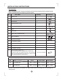
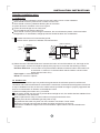
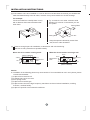
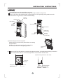
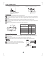
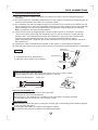
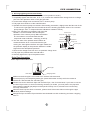
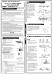
Before using your air conditioner, please read
this manual carefully and keep it for future reference.
FLOOR-STANDING SPLIT TYPE
ROOM AIR CONDITIONER
Please read this installation manual completely
before installing the product.
If the power cord is damaged, replacement work
shall be performed by authorised personnel only.
Installation work must be performed in accordance
with the national wiring Standards by authorised
personnel only.
Contact an authorised service technician for
repair, maintenance or installation of this unit.
CONTENTS
SAFETY PRECAUTIONS
Warning .............................................................................................................................................2
Caution ..............................................................................................................................................2
INSTALLATION INSTRUCTIONS
Accessories .......................................................................................................................................3
Selecting installation place ................................................................................................................4
PIPE CONNECTION
Refrigerant pipe connection ..............................................................................................................7
Drain pipe connection ......................................................................................................................10
ELECTRICAL WORK
Wire connection ...............................................................................................................................11
TEST RUNNING
Test running ...................... .............................................................................................................13
Read This Manual
Inside you will find many helpful hints on how to install and test the air conditioner properly.
All the illustrations and specifications in the manual are subject to change without prior notice for product
improvement. The actual shape should prevail.
CAUTION
Contact an authorised service technician for repair or maintenance of this unit.
Contact an authorised installer for installation of this unit.
The air conditioner is not intended for use by young children or infirmed persons without supervision.
Young children should be supervised to ensure that they do not play with the air conditioner.
If the power cord is to be replaced, replacement work shall be performed by authorised personnel only.
Installation work must be performed in accordance with the National Wiring Standards by authorised
personnel only.
1
SAFETY PRECAUTIONS
Read the follow SAFETY PRECAUTIONS carefully before installation.
Electrical work must be installed by a licensed electrician. Be sure to use the correct rating
and main circuit for the model to be installed.
Incorrect installation due to ignoring of the instruction will cause harm or damage.
The seri ousness is classified by the following indications.
WARNING
This symbol indicates the possibility of death or serious injury.
CAUTION
This symbol indicates the possibility of injury or damage to property.
The items to be followed are classified by the symbols:
Symbol will background white denotes item that is PROHIBITED from doing.
WARNING
1) Engage dealer or specialist for installation. If installation done by the user is defective, it will cause water
leakage, electrical shock fire.
2) Install according to this installation instructions strictly. If installation is defective, it will cause water leakage,
electrical shock fire.
3) Use the attached accessories parts and specified parts for installation. otherwise, it will cause the set to fall,
water leakage, electrical shock fire.
4) Install at a strong and firm location which is able to withstand the set,s weight. If the strength is not enough or
installation is not properly done, the set will drop and cause injury.
5) For electrical work, follow the local national wiring standard, regulation and this installation instructions. An
independent circuit and single outlet must be used. If electrical circuit capacity is not enough or defect found in
electrical work, it will cause electrical shock fire.
6) Use the specified cable and connect tightly and clamp the cable so that no external force will be acted on
the terminal. If connection or fixing is not perfect, it will cause heat-up or fire at the connection.
7) Wiring routing must be properly arranged so that control board cover is fixed properly. If control board cover
is not fixed perfectly, it will cause heat-up at connection point of terminal, fire or electrical shock.
8) When carrying out piping connection, take care not to let air substances other than the specified
refrigerant go into refrigeration cycle. Otherwise, it will cause lower capacity, abnormal high pressure
in the refrigeration cycle, explosion and injury.
9) Do not modify the length of the power supply cord or use of extension cord, and do not share the
single outlet with other electrical appliances. Otherwise, it will cause fire or electrical shock.
CAUTION
1) This equipment must be earthed and installed with earth leakage current breaker. It may cause electrical
shock if grounding is not perfect.
2) Do not install the unit at place where leakage of flammable gas may occur. In case gas leaks and
accumulates at surrounding of the unit, it may cause fire.
3) Carry out drainage piping as mentioned in installation instructions. If drainage is not perfect, water
may enter the room and damage the furniture.
4) The appliance shall be installed in accordance with national wiring regulations.
5) Do not operate your air conditioner in a wet room such as a bathroom or laundry room.
6) An all-pole disconnection device which has at least 3mm clearances in all poles , and have a
leakage current that may exceed 10mA, the residual current device (RCD) having a rated residual
operating current not exceeding 30mA, and disconnection must be incorporated in the fixed wiring
in accordance with the wiring rules.
2
INSTALLATION INSTRUCTIONS
Accessories
Before installing, please check the available accessories according to the list given below.
Please carefully keep the temporarily useless parts.
Quantity
Part Name
Bushing-Sleeve Cover
1
5
Sound/Heat Insulation Sleeves
2
6
Seal
1
7
Drain joint
1
Pipe - hole - protection Ring
1
Remote Battery
2
Remote Controller
1
11
Connection Cables
1
12
Remote controller manual
1
13
User's manual
1
14
Installation manual
1
8
Cord protection rubber ring
(If the cord clamp can not fasten the cord for the
small size of the cord, please use the cord protection
rubber ring(supplied with accessories) to wrap on the
cord, then fix it with the cord clamp.)
15
ADJUST
AUTO
COOL
DRY
HEAT
10
¡
SET TEMPERATURE (C)
HEALTH
HIGH
9
TIMER ON
4
TIMER OFF
2
LED
DISPLAY
Flat Washers
SLEEP
3
RESET LOCK
2
SWING
Self-tapping Screw 3.9×25
CLEAN
AIR
DIRECTION AIR
2
LOW
1
Safety Lock
ON/OFF FAN SPEED
1
Illustrations
MODE
NO.
1(on some models)
Refrigerant Pipe (optional)
.
capacity(Btu/h)
NO.
Name
16
Liquid Side Size
17
Gas Side Size
21000-36000
36000-55000
Diam.: 6.35mm
Diam.: 9.52mm
Diam.: 12.7mm
Diam.: 12.7mm
Diam.: 15.9mm
Diam.: 19mm
18000
If there is any difference between the above table and the Packing List, the Packing List
shall prevail.
3
INSTALLATION INSTRUCTIONS
Selecting installation place
..
..
..
1-1 Indoor Unit
Ensure the spaces indicated by arrows from the wall, ceiling, fence or other obstacles.
There should not be any heat source or steam near the unit.
There should not be any obstacles blocking the air circulation.
A place where air circulation in the room is good.
A place where drainage can be easily done.
Do not install the unit near the door way.
There should not be any direct sunlight. Otherwise, the sun will fade the plastic cabinet and affect
its appearance. If unavoidable, sunlight prevention should be taken into consideration.
Please stand the unit in hard and flat ground;
Please reserve space for installation and maintenance.
( wall or obstacle )
( Ceiling)
5cm
(min)
(1)
Rear
>30(cm)
(min)
4cm
(min)
Front
>200cm
50cm(min)
50cm(min)
(2) Please check the elevation difference between the indoor unit and the outdoor unit, the length of the
refrigerant pipe, and the curved places (bend) of the pipe are no more than the following numbers:
Elevation difference: no more than 10 M (if the elevation difference between indoor and outdoor unit
is more than 10 meters, it is recommended that the outdoor unit be located
higher than the indoor unit.)
Pipe length: no more than 20 M
Bends: no more than 3 places
1-2 Outdoor Unit
The outdoor unit should be put in a position that guarantees the minimum space for sufficient air
circulation and to allow maintenance work and the connections of electrical and refrigerant circuit lines.
It may be installed on a floor or flat roof or wall-mounted, provided its weight is properly supported and
there is no transmission of vibration to the adjacent rooms.
(1) Before installing the outdoor unit, you should:
If an awning is built over the unit to prevent direct sunlight or rain, be careful that heat radiation from
the condenser is not obstructed.
Select a place that is easy to connect indoor unit's pipe and electric wires.
Avoid a place where combustible gas may leak or stay.
Pay attention that water may drain out of the outdoor unit while in "Heat" mode.
Ensure the enough space around the back and sides and the front of the unit.
Take the air conditioner weight into account and select a place where noise and vibration are
minimum.
4
INSTALLATION INSTRUCTIONS
(2) If the outdoor unit is to be installed on a roof or where no constructions are around, you should avoid
hard wind blows directly to the air outlet, because it may cause trouble for air-flow shortage.
For example:
Let the air outlet face a wall (if there is one)
with a distance about 300 centimeters between them.
Try to make the air outlet vertical to wind
direction if it is known in the season you use
the system.
Strong Wind
C
A
B
Strong Wind
Air Out
Keep the spaces indicated by arrows from
wall, fence or other obstacles.
(3)
Reserve enough space for installation, maintenance and unit-functioning.
Remove as many obstacles as possible nearby.
When the air-in surface is facing a wall
When the air-out surface is facing a wall
Air In
(Wall or Obstacle)
>30cm
Air In
Air In
Air Out
Air In
Maintenance
Side
Air Out
>30cm
Maintenance
Side
>50cm
Maintenance
Side
>300cm
>50cm
(Wall or Obstacle)
.
Caution
Installation in the following places may cause trouble. If it is unavoidable to use in such places, please
consult with the dealer.
(1) A place full of machine oil.
(2) A saline place such as coast.
(3) Hot-spring resort.
(4) A place full of sulfide gas.
(5) A place where there are high frequency machines such as wireless installation, welding
machine, medical facility.
(6) A place of special environmental conditions.
5
INSTALLATION INSTRUCTIONS
1 Indoor Unit
(1) Anti-falling
To prevent the indoor unit from falling, you must:
Pay full attention to the unit because its long outer shape makes it easy to fall;
Firmly fix the unit to the wall(using two 3.9*25 screws) or in the ground(by using 2 M8 screws fix
the chassis on the ground ) to avoid accidental falling.
Safety Lock
Screws
3.9×25
Flat washer
Air Outlet
Screws
3.9×25
Flat washer
Screw hole
(on the unit)
Screws
3.9×10
(on the unit)
Air Inlet
(2) Dismounting the lower front panel
Please take off the lower front panel before connecting
the pipes/wires.
Pull down the two knobs on the grille, take off the
two screws, then the air-inlet grille goes free.
(3)
Lower front
panel
Remove the Pipe Clip before connecting the pipes and wiring; fix it again after finishing connection.
Use accessories 4 and 8 to connect the pipes/wires on both sides and back side.
Pipe/wire-hole positions on both sides
Drain Pipe
Refrigerant Pipe
Reamer Joint
Reamer Joint
Wiring
Holeφ35
6
Refrigerant/drain
Pipe holeφ85
PIPE CONNECTION
Pipe/wire-hole position on back side
Wiring
Holeφ35
Pipe/wire-hole position on the bottom
Refrigerant/drain
Pipe holeφ85
Refrigerant/drain
Pipe holeφ85
2 Outdoor Unit
Ship the a/c to the installation place originally packed;
Be careful while hanging the unit because the center of gravity of the unit is not centralized;
Do not make the angle of inclination more than 45 degrees while shipping;(Avoid horizontal
storage)
Be sure the electric insulation work is well done if installed on metal ceiling / wall.
Fix the unit feet with bolts (M10/M8). Be sure the unit is fixed strongly enough to against blast
or earthquake.
Make a concrete basement to the unit by the above references.
A
Air inlet
845x700x320
560
335
900x860x315
590
333
940x1245x360
602
380
990x965x345
623
366
900x1170x350
590
378
938x1369x392
633
404
B
Air inlet
Outdoor unit dimension Mounting dimensions
mm(WxHxD)
A(mm)
B(mm)
Air outlet
Refrigerant Pipe Connection
The refrigerant pipe and the drain pipe should be heat-insulated to avoid condensing and
water-dropping.
A reamer joint is adopted to connect the indoor unit with the outdoor unit.
The refrigerant pipe is used to connect indoor and outdoor units, showed as below.
NOTE
Polythene pipe
Heat-insulation cover
The pipe can not be curved for more than 3 times.
Cover all exposed reamer joint pipes and refrigerant
pipes with heat-insulation material.
Bendable
Reamer Joint
7
Outdoor
Unit
PIPE CONNECTION
1. Connecting Of Refrigerant Pipe
(1) Only the correctly installing of indoor and outdoor unit done, can the refrigerant pipe be
connected.
(2) The cut-off valves are completely closed before ex-work. Before connecting the refrigerant pipe, be
careful to check whether the valves are completely closed.
(3) The connection procedure of refrigerant pipe: first, unscrew the two valves on the outdoor unit and
the pipe-jointing nut on the indoor unit(please save them care fully). Please connect the refrigerant
pipe according to the manual, the pipe-jointing nut should be screwed tightly and no leakage.
Note: you need two wrenches to make balance.
(4) When the connection of refrigerant pipe is finished, before power on the system, you should
vacuum the indoor unit through the maintenance port on the cut-off valves, or open the highpressure valve, and exhaust the air through the maintenance port on the low-pressure valve
(closed). It will take about ten seconds. Then screw the maintenance port on tightly.
(When supplement the refrigerant, fill from the maintenance port of the low-pressure valves on
the outdoor unit ).
(5) Open all the valves completely before power on the system, or it will cause low efficiency.
(6) Gas leak check. Make sure no gas comes from the connections by using leak detector or soap water.
Indoor unit
check point
Caution
D
C
Electrical box
A: Lo packed valve B: Hi packed valve
C and D are ends of indoor unit connection.
Outdoor unit
check point
B
A
Caution in Handling the Packed Valve
Open the valve stem until it hits against the stopper. Do not try to open it further.
Securely tighten the valve stem cap with a spanner or the link.
Outdoor unit Refrigerant
A
Flare nut
Indoor unit
C
Stopper
Cap
D
B
Packed valve
Valve body
Valve stem
Half union
Notes for the bendable pipe
The bendable pipe should be used on the indoor side;
Bend angel can not exceed 90 degrees;
Bend the pipe in the middle place if possible, as for bend radius, the bigger the better;
The bendable pipe can not be bent for more than 3 times.
Bend the thin pipe
While bending, expose the pipe by cutting the concave gap on the bending heat-insulation pipe(roll
it with soft band after bent).
To avoid pipe deformation, the radius is the bigger the better.
Use a pipe-bending device to make the compact bending pipe.
8
PIPE CONNECTION
Use thumb to curve the pipe
Untie the pipe,
make it straight
Min. Radius 100 mm
2. Using bronze pipe selling in market
Completely shut the cut-off valves of the outdoor unit (as ex-work status). After the refrigerant pipe
has been connected with both the indoor and outdoor unit, let the air exhaust out from the maintenance
gap on the low-pressure cut-off valves of the outdoor unit. Screw the nuts tightly on the maintenance
gap after the air has been discharged.
3. To make the refrigerant pipe unblocked completely
you should keep the cut-off valves of the outdoor unit completely opened after you have finished the
above steps (step1 or step 2)
NOTE:
Before screwing the reamer nut, wipe the pipe and it,s surface with refrigerant oil;
After connecting, using soap-water or leakage-checker to make sure there is no leakage occurs;
Use two wrenches to connecting the pipes.
Torque wrench
Spanner
Indoor unit
Outdoor unit
4. Refrigerant charging
The correct refrigerant charging amount to the 5-meter-long pipe of the outdoor unit is marked on the
Product Data Plate. If you have to use longer pipe for every meter plus pipe, the refrigerant should be
added according to the following calculation.
Connective Air purging
pipe length method
Less than Use vacuum
pump
5m
Additional amount of refrigerant to be charged
Liquid side: 6.35
Liquid side: 9.52
Liquid side: 12.7
More than Use vacuum
R22:(Pipe length-5) X 15g/m R22:(Pipe length-5) X 30g/m R22:(Pipe length-5) X 60g/m
5m
pump
R410A:(Pipe length-5) X 15g/m R410A:(Pipe length-5) X 30g/m R410A:(Pipe length-5) X 60g/m
NOTE: If you are using a pipe purchased in the market, please make sure the heat-insulation
material is the same as what we supply(at least 12mm in thickness).
Check whether the height drop between
the indoor unit and outdoor unit,the length
of refrigerant pipe,and the max height
drop meet the following reqirements:
Model
When outdoor unit is top
24K
When outdoor unit is bottom
When outdoor unit is top
36K
When outdoor unit is bottom
When outdoor unit is top
42K/48K When outdoor unit is bottom
When outdoor unit is top
60K
When outdoor unit is bottom
9
The length of The max
refrigrant pipe height drop
25
25
30
30
50
50
50
50
12
9
20
12
25
20
25
20
PIPE CONNECTION
5. Air Purging(Using the Vacuum Pump)
(For method of using a manifold valve, refer to its operation manual.)
1. Completely tighten the flare nuts, A, B, C, D, connect the manifold valve charge hose to a charge
port of the low-pressure valve on the gas pipe side.
2. Connect the charge hose connection to the vacuum pump.
3. Fully open the handle Lo of the manifold valve.
4. Operate the vacuum pump to evacuate. After starting evacuation, slightly loose the flare nut of the
Lo valve on the gas pipe side and check that the air is entering.(Operation noise of the vacuum
pump changes and a compound meter indicates 0 instead of minus).
5. After the evacuation is complete, fully close the
Manifold valve
handle Lo of the manifold valve and stop the
Compound meter Pressure gauge
operation of the vacuum pump. Make evacuation
for 15 minutes or more and check that the
-76cmHg
compound meter indicates -76cmHg(-1x10⁵Pa).
Handle Hi
Handle Lo
6. Turn the stem of the packed valve B about 45o
Charge hose
Charge hose
counterclockwise for 6~7 seconds after the gas
Vacuum pump
coming out, then tighten the flare nut again. Make sure
the pressure display in the pressure indicator is a little
higher than the atmosphere pressure.
Low pressure valve
7. Remove the charge hose from the Low pressure charge hose.
8. Fully open the packed valve stems B and A.
9. Securely tighten the cap of the packed valve.
Drain Pipe Connection
Drain Pipe of The Indoor Unit
Drain pipe
Drain Pipe
Wrapping Band
Make sure the drain pipe is connected to the outdoor side downward;
The hard polyvinyl chloride(PVC)plastic pipe (external diameter 26 mm) sold in the market is
suitable for attached with the soft drain pipe;
Please connect the Soft Drain Pipe with the Drain Pipe , then fix it with band; if you have to connect
the Drain Pipe indoors, to avoid condensing caused by air intake, you must protect the pipe with
heat-insulation material (polyethylene with Specific Gravity of 0.03, at least 9 mm in thickness),
and wrap it with band.
After the Drain Pipe has been connected, please check if the water drains out through the pipe
efficiently without leakage.
Refrigerant Pipe and Drain Pipe should be heat-insulated to avoid condensing and water -dropping
later on.
10
ELECTRICAL WORK
Operation Tips
1. Wire connecting
NOTE: The outdoor unit you purchased may be
look like one of the following, and the wire connecting
is different.
Cover
1. Remove the right-side front panel from the unit .
2. Connect the connective cables to the terminals as
identified with their respective matched numbers on
the terminal block of indoor and outdoor units.
3. Secure the cable onto the control board with the cord clamp.
4. Wiring connection must be done strictly according to the
"Wiring Diagram"located on the side panel of air conditioner .
5. Follow the instructions of wiring connection in this manual,
never attempt to modify the wiring by yourself.
CAUTION: Wrong wiring connections may cause some electrical
parts to malfunction. The air conditioner must be grounded well.
2. Wire-connecting Brief Diagram(for details refer to Wire-connecting Diagram)
Power supply
Power cord of Indoor unit
Main Switch/Fuse
(Locally purchased)
Indoor/outdoor unit
connective cable (signal wire)
(cooling only models without)
Indoor/outdoor unit
connective cables
Indoor Unit
Outdoor
unit
Sensor connective cable
(cooling only models without)
Power supply
Power cord of Indoor unit
Main Switch/Fuse
(Locally purchased)
Indoor/outdoor unit
connective cable (signal wire)
(cooling only models without)
Indoor/outdoor unit
connective cables
Outdoor Unit
Indoor
unit
Sensor connective cable
(cooling only models without)
11
Screw
Model A
ELECTRICAL WORK
Power supply Power supply
Switch/Fuse
(Locally purchased)
Power wiring of Indoor unit
Power wiring of outdoor unit
Indoor
Unit
Out door
Unit
Ground wiring
Weak elec-signal link wiring
Ground wiring
Note: The power supply of the unit is subject to the wiring diagram above.
Note: Some models is equipped with a cord having a plug, So a wall outlet shall be properly
installed.
1. Wire connecting
1. Remove the right-side front panel from the unit .
2. Connect the connective cables to the terminals as
identified with their respective matched numbers on
the terminal block of indoor and outdoor units.
3. Secure the cable onto the control board with the cord clamp.
4. Reinstall the right-side front panel to its original position after
finishing the wire connection.
5. Wiring connection must be done strictly according to the
"Wiring Diagram"located on the side panel of air conditioner .
6. Follow the instructions of wiring connection in this manual, never
attempt to modify the wiring by yourself.
Connective Cable
Connective Pipe
Right-side
front panel
Model B
CAUTION
Wrong wiring connections may cause some electrical parts to malfunction. The air conditioner must
be grounded well.
12
ELECTRICAL WORK
Connect the cable between the outdoor unit
1. Remove the front air-inlet grille from the indoor unit by loosening the screws.
2. Connect the cable to the indoor unit by connecting the wires to the terminals on the control
board individually according to the outdoor unit connection.
3. Ensure the colour of wires of outdoor unit and the terminal Nos. Are the same to the indoor,s
respectively.
4. Secure the cable onto the control board with the holder.
Model
<48000Btu/h
>48000Btu/h
>48000Btu/h
Power supply
220-240V~ 50Hz
or
220-240V~60Hz
380V~ 50Hz/60Hz
or
380-415V~ 50Hz/60Hz
Input Rated Amp
(Switch/Fuse)
32/25A
Power Cord Size
2
63/50A
>2.5mm
2
>2.5mm
16/16A
>1.5mm
2
NOTE: The cable size and the current of the fuse or switch are determined by the maximum current
indicated on the nameplate which located on the side panel of the unit. Please refer to the
nameplate before selecting the cable, fuse and switch.
NOTE:
1. Please pay attention to the surroundings (environmental temperature, direct sunlight, rain etc.)
2. We consider the minimal size of the metal core as the wire size. So it is recommended you
adopt a thicker one as the power conducting wire so as to avoid power decrease;
3. Connect the grounded wire to both indoor and outdoor units;
4. This table is just an on-site wire-connecting example. For details, please refer to relative
National criteria.
5-3. Electrical safety check
Perform the electric safe check after completing installation:
1. Insulated resistance
The insulated resistance must be more than 2MΩ.
2. Grounding work
After finishing grounding work, measure the grounding resistance by visual detection and
grounding resistance tester. Make sure the grounding resistance is less than 4Ω.
3. Electrical leakage check (performing during test running)
During test operation after finishing installation, the serviceman can use the electroprobe and
multimeter to perform the electrical leakage check. Turn off the unit immediately if leakage
happens. Check and find out the solution ways till the unit operate properly.
Test Running
Perform test running operation after finishing gas leak and electrical safety check. The test operation
time should last more than 30 minutes.
1. Turn on the unit.
2. Press the TEST RUNNING button on control panel, the unit will begin TEST RUNNING operation.
3. Check if all the functions works well while in testing operation. Especially check whether the water
drainage of indoor unit is smoothly or not.
4. Press the TEST RUNNING button again till the operation indicator turns dark after finishing the
test operation and the unit stops operation.
13
The design and specifications are subject to change without prior notice for product
improvement. Consult with the sales agency or manufacturer for details.
QS001-BPI
202000192490
20130803