1
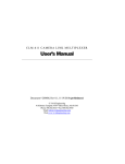
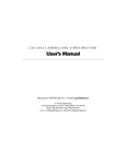
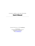
C L R - 1 0 1 C A M E R A L I N K T M R E P E AT E R User’s Manual Document # 200057, Rev 1.0, 4/28/03 Vivid Engineering 418 Boston Turnpike #104 • Shrewsbury, MA 01545 Phone 508.842.0165 • Fax 508.842.8930 Table of Contents 1. Introduction 1 1.1. Overview 1 1.2. Features 2 1.3. Functional Description 3 1.4. Typical Application 4 1.5. Specifications 5 2. Interface 6 2.1. Front Panel Connections 6 2.1.1. Video Connector Signals 7 2.1.2. Cable Shield Grounding 7 2.2. Rear Panel Connections 9 3. Mechanical 10 3.1. Dimensions 10 3.2. External Power Supply 10 4. Regulatory Compliance 11 4.1. FCC Compliance Statement 11 4.2. Canadian Compliance Statement 11 5. Revision History 12 1. Introduction 1.1. Overview The CLR-101 Camera LinkTM1 Repeater supports applications requiring separation between camera and frame grabber in excess of the maximum Camera LinkTM cable length (10 meters). One Camera LinkTM cable connects the camera to the CLR-101, and a second cable connects the CLR-101 to the frame grabber. This solution provides a 20 meter reach between camera and frame grabber using a pair of standard 10m Camera LinkTM cables. Additional CLR-101s and cables may be added, as required, to support greater distances. The CLR-101 supports the Camera LinkTM “base” configuration. “Medium” configuration applications are supported using two CLR-101s. Housed in a sturdy, compact aluminum enclosure, the CLR-101 Camera LinkTM Repeater is well suited for industrial environments. Vivid Engineering CAMERA Camera Link Repeater CLR-101 FRAME GRABBER The Camera LinkTM interface standard enables the interoperability of cameras and frame grabbers, regardless of vendor. The Automated Imaging Association (AIA) sponsors the Camera LinkTM program including the oversight Camera Link Committee, the self-certification program, and the product registry. The Camera LinkTM specification may be downloaded from the AIA website, found at www.machinevisiononline.org 1 Camera LinkTM is a trademark of the Automated Imaging Association 1 1.2. Features • Doubles max distance between camera and frame grabber • Uses standard Camera LinkTM cables (not included) • Supports Camera LinkTM “base” configurations • “Medium” configuration support using two CLR-101s • May be cascaded for greater distances • Sturdy, compact aluminum enclosure • External power supply included • 3-year warrantee • Cost-effective solution 2 1.3. Functional Description A block diagram of the CLR-101 is provided in Figure 1-1. The CLR-101 regenerates the “base” configuration signal set defined in the Camera Link Specification. The regenerated signals may then be transmitted an additional distance up-to 10 meters over standard Camera LinkTM cables. The CLR-101 incorporates the connectors, signals, pinouts, and chipset in compliance with the Camera LinkTM specification. The CLR-101 regenerates all the “base” configuration signals, consisting of video data, camera control, and serial communications. Channel Link Receiver Channel Link Transmitter Video Data LVDS Receiver Camera Control Clock Buffer Camera Control Serial Comm Link LVDS Transmitter LVDS Rcvr LVDS Xmtr LVDS Xmtr LVDS Rcvr Serial Comm Link To Camera LinkTM Frame Grabber To Camera LinkTM Camera Video Data CLR-101 Camera LinkTM Repeater Figure 1-1: CLR-101 Block Diagram The CLR-101 is also compatible with second Camera LinkTM cable used in the Camera LinkTM “medium” configuration, enabling a pair of CLR-101s to be used as a repeater in medium configuration applications. The CLR-101 is powered by an external wall plug-in power supply (included). 3 1.4. Typical Application A typical CLR-101 application is shown in Figure 1-2. A Camera LinkTM “base” configuration camera is connected to the CLR-101 via a standard 10m Camera LinkTM cable. A second 10m Camera LinkTM cable is then connected from the CLR-101 to a Camera LinkTM frame grabber. This provides a 20 meter reach between camera and frame grabber. This example uses a single CLR-101 to regenerate the Camera LinkTM signals. Additional CLR-101s and cables may be added, as required, to further increase separation. Medium mode configurations, in which two cables connect the camera to the frame grabber, are supported using two CLR-101s. CLR-101 Camera LinkTM Repeater Vivid Engineering Camera Link Repeater CAMERA Camera LinkTM Camera CLR-101 FRAME GRABBER Standard 10m Camera LinkTM Cables 20 Meter Reach Figure 1-2: CLR-101 Typical Application 4 Camera LinkTM Frame Grabber 1.5. Specifications Table 1-1: CLR-101 Specifications Feature Specification Video Interfaces Camera Link Spec “base” configuration Video Connectors 26-pin MDR type Frequency Range 20 - 66 MHz Chipset National Semi. DS90CR285 / DS90CR286A Power Supply External 6 VDC Wall Transformer Power Jack 2.1 x 5.5 mm, center-positive Power Requirements 230 mA at 6 VDC (typical) Cabinet Dimensions 5.28” (L) x 1.12” (H) x 4.13” (D) Weight 10 oz Operating Temperature Range 0 to 50° C Storage Temperature Range -25 to 75° C Relative Humidity 0 to 90%, non-condensing 5 2. Interface 2.1. Front Panel Connections The CLR-101 Camera LinkTM Repeater front panel is shown in Figure 2-1. The front panel contains two 26-pin MDR video connectors; one for connecting to the camera and one for connecting to the frame grabber. The MDR-26 connectors are 3M p/n 1022655G3VC as specified in the Camera Link Spec. Figure 2-2 identifies the MDR-26 pin positions. Vivid Engineering Camera Link Repeater CAMERA FRAME GRABBER Figure 2-1: CLR-101 Front Panel pin 13 pin 1 pin 26 pin 14 Figure 2-2: MDR-26 Connector Pin Positions 6 CLR-101 2.1.1. Video Connector Signals The front panel MDR-26 video connector signal assignments comply with the Camera LinkTM “base” configuration. The camera connector signal assignments correspond to the frame grabber interface defined in the Camera Link Specification. Conversely, the frame grabber connector assignments are as defined for the camera interface in the Camera Link Specification. This arrangement provides compatibility with standard Camera LinkTM cables. Table 2-1 identifies the signal assignments for the MDR-26 video connectors. 2.1.2. Cable Shield Grounding Camera and frame grabber cable “outer” shields are connected to the CLR-101 aluminum case. Case and endplate contacting surfaces are unpainted, providing a Faraday cage to shield internal circuitry. The case is isolated from the CLR-101 circuitry and the cable “inner” shields, avoiding possible safety concerns. The frame grabber cable “inner” shield connects to circuit digital ground, maintaining signal reference levels between the CLR-101 and the frame grabber. The Camera LinkTM Specification recommends that a provision be incorporated into frame grabbers that enable the inner shields be tied to digital ground either directly, or through a parallel R/C network. In CLR-101, the camera connector represents the Camera LinkTM frame grabber interface. To incorporate this flexibility, the CLR-101 ties the inner shields from the camera connector to digital ground through 0-ohm resistors. If necessary, the 0-ohm resistors may be replaced with a parallel RC network. 7 Table 2-1: MDR-26 Connector Assignments Camera Link Signal Name Camera Connector Pin # (frame grabber pinout) Frame Grabber Connector Pin # (camera pinout) Signal Direction Inner shield 1 1 N/A Inner shield 14 14 N/A X0- 25 2 CAM → FG X0+ 12 15 CAM → FG X1- 24 3 CAM → FG X1+ 11 16 CAM → FG X2- 23 4 CAM → FG X2+ 10 17 CAM → FG Xclk- 22 5 CAM → FG Xclk+ 9 18 CAM → FG X3- 21 6 CAM → FG X3+ 8 19 CAM → FG SerTC+ 20 7 FG → CAM SerTC- 7 20 FG → CAM SerTFG- 19 8 CAM → FG SerTFG+ 6 21 CAM → FG CC1- 18 9 FG → CAM CC1+ 5 22 FG → CAM CC2+ 17 10 FG → CAM CC2- 4 23 FG → CAM CC3- 16 11 FG → CAM CC3+ 3 24 FG → CAM CC4+ 15 12 FG → CAM CC4- 2 25 FG → CAM Inner shield 13 13 N/A Inner shield 26 26 N/A “FG” = Frame Grabber “CAM” = Camera 8 2.2. Rear Panel Connections The CLR-101 Camera LinkTM Repeater rear panel is shown in Figure 2-3. The rear panel contains a power on indicator, on-off switch, and DC power jack. DC power jack accepts 6 volts DC. Polarity is center-positive. ON POWER 6 VDC Figure 2-3: MDR-26 Connector Pin Positions 9 OFF 3. Mechanical 3.1. Dimensions The CLR-101 Camera LinkTM Repeater cabinet dimensions are shown in Figure 3-1. Note that the dimensions are for the cabinet only. Connectors, switch, hardware, etc are not included in the measurements. The CLR-101 is housed in a sturdy aluminum enclosure. The body is extruded aluminum, with detachable front and rear endplates. Camera Link Repeater CLR-101 1.12" 4. 13 " Vivid Engineering CAMERA FRAME GRABBER 5.28" Figure 3-1: CLR-101 Cabinet Dimensions 3.2. External Power Supply The CLR-101 is powered by an external wall-mount 6 VDC power supply (included). The power supply incorporates a standard 2.1 x 5.5 mm DC power plug. Power plug polarity is center-positive. The power supply is UL and CSA listed. An EMI filter is located on the power cord near the DC power plug. The filter suppresses EMI emissions, ensuring regulatory limits are not exceeded. Do not remove the EMI filter. The CLR-101 is protected by an internal resettable fuse. 10 4. Regulatory Compliance 4.1. FCC Compliance Statement This equipment has been tested and found to comply with the limits for a Class A digital device, pursuant to Part 15 of the FCC Rules. These limits are designed to provide a reasonable protection against harmful interference when the equipment is operated in a commercial environment. Operation of this equipment in a residential area is likely to cause harmful interference in which case the user will be required to correct the interference at his/her own expense. Changes or modifications not expressly approved by the party responsible for compliance could void the user’s authority to operate the equipment. 4.2. Canadian Compliance Statement This digital apparatus does not exceed the Class A limits for radio noise emissions from digital apparatus set out in the Radio Interference Regulations of the Canadian Department of Communications. 11 5. Revision History Table 5-1: CLR-101 User’s Manual Revision History Document ID # Date 200057-1.0 4/28/03 Changes Initial release of manual 12