1
GRAFIN2 USER'S MANUAL
(004-02704-01)
C o p y r i g h t e 1984, Metheus Corporation
5510 N.E. El a m Young Parkway, Hillshoro, OR 97123
DISCLAIMER
The information in this manual is subject to change without notice.
Metheus Corporation makes no warranty of any kind with regard to
this material, including, but not limited to, the implied warranties
of merchantability and fitness for a particular purpose. Metheus
Corporation assumes no responsibility for any errors that may
appear in this manual. Metheus Corporation makes no commitment to update nor to keep current the information contained in
this document.
Metheus Corporation assumes no responsibility for the use of any
circuitry other than circuitry embodied in a Metheus product. No
other circuit patent licenses are implied.
Metheus software products are copyrighted by and shall remain the
property of Metheus Corporation. Use, duplication, or disclosure is
subject to restrictions stated in your Metheus software license.
No p a r t of this document may be copied or reproduced in any form
or by any means without the prior written consent of Metheus Corporation.
METHEUS, AXIA, FLASH-ffll, and PIXBLT are t r a d e m a r k s of Metheus
Corporation.
ii
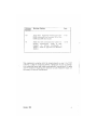
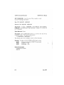
Revision
Number
Revision History
Date
-00
First Issue. Supports version 2.5 of the
Q500 microcode and version
of the
Q400 and Q300 microcode.
7/84
-01
Adds two new commands for tablet-toscreen conversions.
Adds a new
chapter on writing commands in
FORTH. Adds an appendix on Metheus
FORTH.
10/84
This equipment complies with the r e q u i r e m e n t s in part. 15 of FCC
rules for a class A computing device. Operation of this equipment
in a residential area may cause unacceptable interference to radio
and TV reception requiring the operator to t a k e whatever steps are
necessary to correct interference.
October, 1984
iii
I
SERVICE INFORMATION
Contact the Graphics System Service Center (GSSC) when you need
any Metheus graphics system repaired, replaced, or upgraded.
This includes both hardware and firmware products. Following
these simple instructions when you call or write will insure the
quickest possible response to your request.
(1) You must provide these three items when you call or write to
the service center:
Model Number
Serial Number
Purchase Order Number
Model numbers and serial numbers are m a r k e d on the outside
of the chassis packaged products, on the board artwork, or on
the firmware. The purchase order n u m b e r authorizes the service center to charge for services. They can also provide the
latest upgrade and service contract costs.
(2) Obtain a Return Authorization (RA) n u m b e r from the service
center BEFORE sending any equipment. Use this number in all
correspondence.
Contact the Service Center at this address:
Graphics System Service Center
Metheus Corporation
5510 N. E. Elam Young Parkway
Hillsboro, Oregon 97123
(503) 640-8000
i.
PREFACE
This manual is for new users of GRAFIN2. GRAFIN2 replaces the
earlier GRAFIN option. This manual describes the commands and
features of GRAFIN2. It assumes that you know how to use the
Omega Display Controller and your graphics input device. You do
not need to know how to use GRAFIN.
GRAFIN2 is an optional hardware interface package for Omega
display controllers. GRAFIN2 is compatible with all host interfaces
that support the Q300, Q400 and Q500 series Display Controllers.
GRAFIN2 commands are used in programs t o allow input from a
graphics tablet or mouse. GRAFIN2 supports the Summag rap hies 1
tablet and mouse, and GTCO2 tablet.
GRAF1N2 is not compatible with GRAPTN. The differences between
them and the installation procedures for GRAFIN2 are discussed in
Appendix A and B.
MANUAL OVERVIEW
This manual contains three chapters and three appendixes:
o Chapter 1 defines t e r m s and discusses t h e GRAFIN2 commands
by function.
o Chapter 2 discusses the GRAFIN2 commands in detail,
o Chapter 3 illustrates how to write customized GRAFI.N2
commands using the Metheus version of FORTH3,
o Appendix A contains the installation procedure for GRAFIN2.
o Appendix B describes the differences between GRAFIN2 and
GRAFIN. •
o Appendix C summarizes Metheus FORTH.
^ummagraphics is a registered tradename of Summagraphics Corporation.
GTC0 is a registered tradename of GTCO Corporation.
2
3
FORTH is a registered trademark of FORTH, Inc.
October, 1984
vii
GRAFIN2 User s Martuai
Preface
NOTE
If you are installing GRAFIN2 or upgrading GRAFIN to GRAFIN2,
you should read Appendix A first. Installation should be peiformed by a qualified service person only.
RELATED PUBLICATIONS
AXIA Graphics Package User's Manual, Order Number
FORTRAN Opcode Library User's Manual, Order Number
0400 User's Manual, Order Number
004-01065
0500 User's Manual, Order Number
004-02207
004-01086
004-01 705
The Micro FORTH Primer, FORTH, Inc., Manhattan Beach, CA, 1978
FORTH Fundamentals,
viii
Dilitheum Press, Beaverton, OR, 1983.
CONTENTS
CHAPTER 1
OVERVIEW
Definition of Terms
GRAFIN2 Commands
Environment Commands
Cursor-Tracking Commands
Event-Queue Commands
Initializing GRAFIN2
GRAFIN2 Example
CHAPTER 2
GRAF1N2 COMMAND DICTIONARY
Crosshair Cursor
Cursor Off
Cursor On
Event Count
Flush Q
Init GRAF1N2
Inquire Error
Inquire Version
Read Current Position
ReadQ...
Read Q and Wait
Rubberband Box
Rubberband Line
Set Clip Mode
Set Cursor Size
Set Offset/Scale
Set Q Mode
Set Screen Size
Set Tablet Size
Set Wrap Mode
Sketch
Write Tablet
October, 1984
1-1
1-4
1-5
1-6
1-7
1-8
1-9
2-2
2-3
2-4
2-5
2-6
2-7
2-8
2-9
2-10
2-11
2-12
2-13
2-14
2-15
2-16
2-17
2-20
2-22
2-23
2-24
2-25
2-26
ix
Contents
CHAPTER 3
WRITING CUSTOMIZED GRAFTN2 COMMANDS
FORTH Fundamentals
Definition of Terms
Using the Stack
Extending FORTH With Subroutines
Implementing the MINMAX Routine
Learning FORTH
Method One - Hardware Direct
Method Two - Downloading
Command Examples
Writing Custom Cursors
Implementing the Rubberband Line Cursor
Stack Management With SEXEC
Implementing the Sketch Cursor
Implementing the TV Cursor
Implementing Grid and Grid-Drawing Routines
GRAFIN2 Subroutines, Variables, and Pointers
GRAFIN2 Subroutines
Scalar Variables
Pointer Variables
GRAF1N2 Users Manual
3-1
3-2
3-2
3-3
3-5
3-5
3-6
3-7
3-8
3-8
3-9
3-11
3-12
3-14
3-16
3-19
3-19
3-23
3-24
APPENDIX A
GRAFTN2 INSTALLATION
APPENDIX B
GRAFIN AND GRAFIN2 DIFFERENCES
APPENDIX C
METHEU S FORTH
Syntax Changes
General Purpose Additions
Summary Tables
Deletions
C-l
C-2
C-3
C-10
October, 1984
Contents
GRAFIN2 User s MariUcx-
FIGURES
1-1.
1-2.
1-3.
3-1.
3-2.
3-3.
3-4.
3-5.
3 6.
3-7.
3-8.
3-9.
A-l.
A-2.
A-3.
A-4.
Button ID Formats
Clip Mode and Wrap Mode
Sample of GRAFIN2 Commands
Typical Stack Usage
"Sum7" Subroutine
Executing the "Sum7" Routine
Implementing the ,fMinmax" Routine
An Installation Routine
Implementing the Rubberband Line Cursor
Implementing the Sketch Cursor
Implementing the TV Cursor
Implementing Grid-Drawing Routines
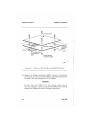
Position of t h e Interface and GRAFIN2 Boards
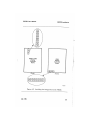
Installing the Omega Microcode PROMs
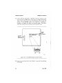
The GRAFIN2 Data Transfer-Switch
!
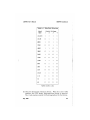
RS-232 Pin Configuration for GRAFIN2
1-2
1-3
........ 1-10
3-3
3-4
3-4
3-5
3-8
3-10
3-13
3-15
3-18
A-2
A-3
A-4
A-6
TABLES
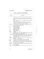
1-1.
1-2.
1-3.
1-4.
2-1.
2-2.
2-3.
3-1.
3-2.
A-l.
GRAFIN2 Commands
Environment Commands
Cursor-Tracking Commands
Event-Queue Commands
Decimal and Hex Scale Factors
Tablet-To-Screen Conversions (Hexadecimal)
Tablet-To-Screen Conversions (Decimal)
FORTH Terminology
GRAFIN2 FORTH Commands
Data Rate Selection
October, 1984
1-4
1-5
1-7
1-8
2-18
2-18
2-18
3-2
3-7
A-5
»
Contents
GRAF1N2 Users Manual
TABLES
C-l. Looping and Conditional Primitives
C-2. Arithmetic and Logical Words
C-3. Compiler Directives
C-4. Defining Words
C-5. I/O Words
C-6. Memory References
C-7. Relational Operators
C-8. Stack Words
C-9. System Words
C-10. System Variables
C-3
C-4
C-5
C-6
;.C-6
C~7
C-7
C-8
C-9
C-9
October, 1984
Chapter 1
OVERVIEW
This chapter contains four sections:
o
o
o
o
Definition of terms used in this manual
The GRAFIN2 commands listed by function
A discussion of the GRAFIN2 initialization commands
An example of GRAFIN2 use.
DEFINITION OF TERMS
The GRAFIN2 interface accepts graphics input from a bit-pad,
tablet, or mouse. In this manual, the input device is referred to as
the tablet. The tracking part of the tablet (the stylus, puck, or
mouse) is referred to in this manual as t h e mouse. The mouse's
position is indicated on the screen by the cursor.
GRAFIN2 keeps track of button events. Button event information
includes which button on the mouse was pressed (the button ID),
and the coordinates when the button was pressed. Button events
are stored in the button event queue. Events are read from the
queue in first-in, first-out order. A button event can be defined as
the push of a button (leading edge mode), the release of a button
(trailing edge mode), the button held down (level mode), or the
push and release of the button (both edge mode ~ two events are
recorded).
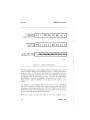
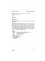
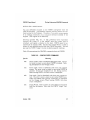
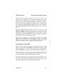
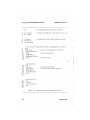
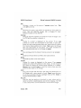
The button ID byte is identical to the data format byte sent from
the tablet. The button ID is formed from the button information
bits in the Summagraphics Bit Pad One Binary Data Format (bits
FO through F3), the SummaMouse Bit Pad One Data Format (bits L,
M, and R), or the GTCO DIGI-PAD 5 High-Resolution Format (bits
PBl, PBS, PB4, PB8, and PBA). Figure 1-1 illustrates these formats.
Refer to your tablet manual for information on interpreting the
button ID.
October, 1984
1-1
GRAFEN2 User's Manual
Overview
Summagraphics
Bit Pad One
Binary Data Format
p
1
F3
F2
F1
F0
0
0
Summa Mouse
Bit Pad One
Data Format
p
1
0
L
M
R
0
0
GTCO DIG! - PAD 5
High-Resolution Format
1 PBA PB8 PB4 PB2 PB1 X15 X14
F-0081
Figure 1-1. Button ID Formats
The origin (0,0) point on the Omega screen is t h e upper left corner
while on most tablets it is the lower left corner. Several commands
map the tablet to the screen and adjust the coordinate systems
(A default mapping is performed by the INIT GRAFIN2 command.)
Coordinates can be reported to or from the host as either tablet
coordinates or screen coordinates.
Coordinates are given in the
format (X,Y). Each coordinate is two bytes: low-x, high-x; low-y,
high-y.
The borders of the mapped area on the s c r e e n form a bounding
box. This is usually the edge of the screen, but you can also specify
a different bounding box with the SET CLIP MODE and SET WRAP
MODE commands. The coordinates of the c o r n e r s of the bounding
box are always given in screen coordinates.
When the mouse reaches the edge of the a r e a mapped to the
1-2
October, 1984
(
GRAFIN2 User's Manual
Overview
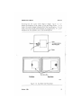
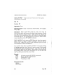
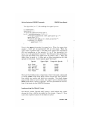
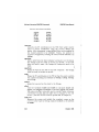
bounding box, the cursor either clips or wraps. Figure 1-2 illust r a t e s t h e behavior of the cursor in clip and wrap modes. In clip
mode, t h e cursor always r e m a i n s within t h e bounding box. In wrap
mode, when t h e mouse moves beyond t h e m a p p e d area, the cursor
r e a p p e a r s on t h e opposite side of the bounding box.
Bounding Box
Clip Mode
Wrap Mode
F-0078
Figure 1-2. Clip Mode and Wrap Mode
October, 1984
1-3
GRAFIN2 User's Manual
Overview
GRAFIN2 COMMANDS
GRAFIN2 commands fall into t h r e e categories:
o Environment commands
o Cursor-Tracking commands
o Event-Queue commands
Environment commands initialize the system, inquire the version
number and inquire the error status. The last section of this
chapter discusses the default initialization conditions and how tc
change them.
Cursor-Tracking commands allow you to select a style of cursor
and to control when it appears on the screen. When the cursor is
displayed, it t r a c k s the mouse.
Event-Queue commands keep t r a c k of button events so t h a t button
input is sent to the host in an orderly manner.
Table 1-1 lists the GRAFIN2 commands. Following the table, each
category of commands is discussed separately.
TABLE 1-1. GRAFIN2 Commands
Environment
Curso r- Trac king
Event-Queue
INIT GRAFIN2
INQUIRE ERROR
INQUIRE VERSION
SET CLIP MODE
SET OFFSET/SCALE
SET SCREEN SIZE
SET TABLET SIZE
SET WRAP MODE
WRITE TABLE
CROSSHAIR CURSOR
CURSOR OFF
CURSOR ON
RUBBERBAND BOX
RUBBERBAND LINE
SET CURSOR SIZE
SKETCH
EVENT COUNT
FLUSH Q
READ CURRENT POSITION
READ Q
READ Q AND WAIT
SET Q MODE
NOTE
Every GRAFIN2 opcode m u s t begin with t h e s e two bytes: the
first is 4Ah (74 decimal) and the second is t h e specific command opcode.
October, 1934
GRAFIN2 User's Manual
Overview
Environment Commands
The environment commands allow you to:
o Map the tablet to the screen
(INIT G.RAFIN2; SET
OFFSET/SCALE; SET SCREEN SIZE; SET TABLET SIZE).
o Set up a bounding box on the s c r e e n (SET CLIP MODE; SET
WRAP MODE).
o Inquire the error status of the system (INQUIRE ERROR),
o Inquire the version of the firmware (INQUIRE VERSION),
o Initialize the tablet (WRITE TABLET).
The environment commands are summarized in Table 1-2.
TABLE 1-2. Environment Commands
Name
INIT GRAFIN2
INQUIRE ERROR
INQUIRE VERSION
SET CLIP MODE
SET OFFSET/SCALE
SET SCREEN SIZE
SET TABLET SIZE
SET WRAP MODE
WRITE TABLET
(*a.)
(*b.)
(*c.)
(*d.)
(*e.)
Hex
Opcode
10
25
26
22
20
11
12
21
24
Decimal
Opcode
16
37
38
34
32
17
18
33
36
Arguments
none
none
none
apC^Xj-Ya)
8: (*c.)
4: (*d.)
4: (*d.)
8:(XvYvXz,Y2)
(*e.)
Returns
none
2: (*a.)
2: (*b.)
none
none
none
none
none
none
first byte = error code; second byte = error count
first byte = version code; second byte = reserved
2 bytes each (16-bit, 2's complement): X-OfTset, X-Scale,
Y-OfTset, Y-Scale
2 bytes each of width and height of s c r e e n or tablet.
variable n u m b e r of bytes (device dependent)
The Arguments and Returns columns in Table 1-2 indicate the
number of bytes (if any) required as input or r e t u r n e d as output.
For example, '^(X^Y^X^Yg)" means that t h e command opcode is
followed by eight bytes of information, in this case, the coordinates
October, 1984
1-5
Overview
GRAFEN2 User's Manual
(four bytes) of one corner of the bounding box and the coordinates
(four bytes) of the opposite corner of the bounding box.
Cursor-Tracking Commands
The cursor tracking commands allow you to select different cursor
types. The cursor types are:
o Crosshair cursor (default) (CROSSHAIR CURSOR, SET CURSOR
SIZE).
o Rubberband box cursor (RUBBERBAND BOX).
o Rubberband line cursor (RUBBERBAND LINE),
o Sketching cursor (SKETCH).
When you select a cursor type, it becomes the currently .selected
cursor and is displayed on the screen. The cursor remains on the
screen until explicitly removed with INIT GRAFIN2 or CURSOR OFF.
Generally, you will want to remove the cursor before drawing overits location. If you draw over the cursor, a shadow image of the
cursor's pixels will remain on the screen.
The CURSOR ON command displays the currently selected cursor.
To change cursors, e n t e r one of the four cursor commands.
The cursor tracking commands are summarized in Table 1-3. The
Arguments and Returns columns indicate the n u m b e r of bytes (if
any) required as input or returned as output. (X,Y) indicates coordinates.
1-6
October, 1984
GRAFIN2 User's Manual
Overview
TABLE 1-3. Cursor-Tracking Commands
Name
CROSSHAIR CURSOR
CURSOR OFF
CURSOR ON
RUBBERBAND BOX
RUBBERBAND LINE
SET CURSOR SIZE
SKETCH
(*a.)
Hex
Opcode
31
3F
30
33
32
23
34
Decimal
Opcode
49
63
48
51
50
35
52
Arguments
none
none
none
4: (X,Y)
4: (X,Y)
4: (*a.)
none
Returns
none
none
none
none
none
none
none
2 bytes each: half width and half height of the crosshair
cursor in pixels
Event-Queue Commands
The event queue stores up to 100 button events from the mouse.
There are two types of event queue commands:
o
o
Commands to manage the event queue itself (EVENT COUNT;
FLUSH Q; SET Q MODE).
Commands t h a t r e t u r n event information to the host (READ
CURRENT POSITION; READ Q; READ Q AND WAIT).
EVENT COUNT keeps track of the n u m b e r of events in the event
queue. If the queue count exceeds 100, new events are ignored and
a queue overflow error will be indicated by the INQUIRE ERROR
command. FLUSH Q clears the event queue. Use the SET Q MODE
command to select which edge is r e c o r d e d and whether tablet or
screen coordinates are reported.
The event queue commands are summarized in Table 1-4. The
Arguments and Returns columns indicates the number of bytes (if
any) required as input or returned as output. (X,Y) indicates coordinates.
October, 1984
1-7
GRAFEN2 User's Manual
Overview
TABLE 1-4. Event-Queue Commands
Hex
Opcode
40
EVENT COUNT
45
FLUSH Q
READ CURRENT POSITION 44
42
READ Q
43
READ Q AND WAIT
41
SET Q MODE
Name
(*a.)
(*b.)
(*c.)
Decimal
Opcode
64
69
68
66
67
65
Argume nts
Re turns
none
none
none
none
none
2: (*c.)
2: (*a.)
none
4. (X,Y)
6: (*b.)
6: (*b.)
none
b
first byte = event count; second byte = reserved
first byte = button ID; second byte = reserved; third through
sixth byte = (X,Y) coordinates
first byte = type of button edge recorded; second byte =
screen or tablet coordinates reported
INITIALIZING GRAFIN2
In general, when you use GRAFIN2 you will want t o initialize the system and possibly change the default conditions. This section looks
at the defaults of the INIT GRAFIN2 command and discusses the
commands used to change the default conditions:
o
o
o
o
o
o
INIT GRAFIN2. Initializes the graphics input environment.
SET SCREEN SIZE or SET TABLET SIZE. Changes the default
value of the screen or tablet size used in mapping.
SET OFFSET/SCALE. Adjusts the mapping of the tablet to the
screen.
SET Q MODE. Selects the button event type and coordinate system.
Cursor-Tracking Commands. Selects and displays a cursor,
SET CLIP/WRAP MODE. Selects the mode a n d defines a bounding box.
INIT GRAFIN2 maps a 2200 by 2200 tablet to a .1024 by 768 pixel
screen. If your tablet or screen is a different size, use SET SCREEN
SIZE or SET TABLET SIZE to change these default values. You can
1-8
October, 1984
.
GRAFTN2 User's Manual
Overview
also use SET OFFSET/SCALE.
INIT GRAFIN2 clears the button event queue, defines a button event
as a leading edge, and specifies that s c r e e n coordinates are sent to
the host. To select another button edge type or change to tablet
coordinates, use SET Q MODE.
INIT GRAFIN2 selects a 33 by 33 pixel crosshair cursor and erases
the cursor f r o m the screen. To display t h e crosshair cursor, use
CURSOR ON or CROSSHAIR CURSOR. To change the size of the
crosshair cursor, use SET CURSOR SIZE. To select a different cursor and display it on the screen, use RUBBERBAND BOX, RUBBERBAND LINE, or SKETCH. CURSOR OFF e r a s e s the cursor f r o m the
screen. CURSOR ON displays the most recently selected cursor.
INIT GRAFIN2 selects clip mode, with a 1024 by 768 pixel screen as
the bounding box. To set a different bounding box, use SET CLIP
MODE. To change to wrap mode and set a bounding box, use SET
WRAP MODE.
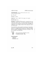
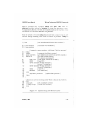
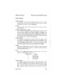
GRAFIN2 EXAMPLE
Figure 1-3 contains sample GRAFIN2 commands, followed by comments. The n u m b e r s in the left-most column r e f e r to the comments and are not p a r t of the GRAFIN2 commands.
October, 1964
1-9
Overview
(1)
(2)
(3)
(4)
(5)
GRAFEN2 User's Manual
4A 10 ~ INIT GRAFIN2
4A 11 00 05 00 04 - SET SCREEN SIZE
4A 41 02 00 -- SET Q MODE
4A 33 64 00 32 01 - RUBBERBAND BOX
4A 44 -- READ CURRENT POSITION (4 bytes r e t u r n e d )
(Move the mouse around the tablet and press a few buttons.)
(6)
(7)
(8)
(3)
4A 42 -- READ Q (6 bytes returned)
4A 45-- FLUSH Q
4A 3F - CURSOR OFF
4E 00 60 - Set color 0 (black) and clear screen
Figure 1-3. Sample of GRAFIN2 Commands
The code in the above example performs these actions:
(1) Initializes GRAFIN2
(2) Adjusts the mapping to an 1280 by 1024 s c r e e n
(3) Sets the queue mode to trailing edge and tablet coordinates
(4) Enables and displays a rubberband box cursor
(5) Reads the c u r r e n t position of the mouse
(6) Reads information from the event queue
(7) Clears the event queue
(8) Removes the cursor from the screen
(9) Sets color to black and clears the screen
1-10
October, 1984
Chapter 2
GRAFIN2 COMMAND DICTIONARY
This chapter alphabetically lists the GRAFIN2 commands. Terms
used in this chapter are defined in Chapter 1. The commands are
summarized by function in tables in Chapter 1.
The command entries in this chapter follow a standard format
which includes:
o
o
o
o
o
o
o
o
Name and short description of the command,
The functional group of the command,
Hex opcode and arguments (if any),
Decimal opcode and arguments (if any),
Definition of the argument(s).
Bytes returned (if any),
Description of the command,
Related commands.
In the command arguments, opcodes are in boldface while variables you must supply are in italics. Be sure to precede the
opcode with 4Ah to indicate a GRAFIN2 command. In the examples,
bytes that you enter are given in boldface; bytes t h a t the computer
returns are given in regular (this style) type.
July. 1984
2-1
GRAF1N2 Command Dictionary
GRAFLN2 User's Manual
CROSSHAIR CURSOR - Selects a crosshair c u r s o r shape.
(Cursor-Tracking Command)
Hex: 31
Decimal: 49
Arguments: None
Bytes Returned None
Description: CROSSHAIR CURSOR selects the crosshair shape for
the cursor and displays the cursor on the screen. While displayed,
the cursor tracks the mouse. The cursor is drawn in the complem e n t a r y color of the existing pixels. A crosshair cursor is the
default shape of the INIT GRAFIN2 and SKETCH commands. The
default size of the cursor is 33 by 33 pixels, s e t by INIT GRAFIN2.
Use the CURSOR SIZE command to change t h e size of the cursor.
The cursor remains on the s c r e e n until removed by INIT GRAFIN2
or CURSOR OFF.
Related Command.
CURSOR OFF
CURSOR ON
INIT GRAFIN2
SET CURSOR SIZE
2-2
July, 1984
GRAFIN2 User's Manual
GRAFIN2 Command Dictionary
CURSOR OFF -- Removes the cursor from t h e screen.
(Cursor-Tracking Command)
Hex: 3F
Decimal: 63
Arguments. None
Bytes Returned None
Description: CURSOR OFF removes the cursor from the screen.
Generally, you will want to remove the c u r s o r whenever you plan to
draw a figure t h a t will overlap t h e cursor. If you do not remove the
cursor (or else move it out of the way), and draw over the cursor, a
shadow image of the cursor's pixels will r e m a i n a t t h a t location.
Related Commands:
CROSSHAIR CURSOR
CURSOR ON
INIT GRAFIN2
RUBBERBAND BOX
RUBBERBAND LINE
SKETCH
July, 1984
2-3
GRAK1N2 Command Dictionary
GKAF1N2 User s Manual
CURSOR ON -- Displays the currently selected cursor.
(Cursor-Tracking Command)
Hex: 30
Decimal: 46
Arguments: None
Bytes Returned: None
Description: CURSOR ON displays the most r e c e n t l y selected cursor. While displayed, t h e cursor tracks t h e mouse. The cursor can
be a crosshair cursor (the default), a r u b b e r b a n d line, a rubberband box or a sketching cursor. Select t h e cursor with the
CROSSHAIR CURSOR, RUBBERBAND BOX, RUBBERBAND LINE, or
SKETCH commands. The INIT GRAFIN2 command selects a 33 by 33
pixel crosshair cursor but does not display it on the screen. The
cursor remains on the screen until removed by INIT GRAFIN2 or
CURSOR OFF.
Related Commands:
CROSSHAIR CURSOR
CURSOR OFF
INIT GRAFIN2
RUBBERBAND BOX
RUBBERBAND LINE
SET CURSOR SIZE
SKETCH
July. 1964
GRAFIN2 User's Manual
GRAF1N2 Command Dictionary
EVENT COUNT ~ Returns the number of events in the event queue.
(Event-Queue Command)
Hex. 40
Decimal: 64
Arguments: None
Bytes Returned: 2 bytes — (low, high) of event count
Description: EVENT COUNT tells you the n u m b e r of items in the
event queue. The event queue holds up t o 100 events. Events t h a t
occur a f t e r the queue is full are ignored. (You can check if the
queue has overflowed with the INQUIRE ERROR command.) Events
are read from the queue in first-in, first-out order. EVENT COUNT
r e t u r n s a 16-bit, two's complement number: low byte, high byte.
Example:
4A 40
1A 00
4Ah m u s t p r e c e d e all GRAFIN2 commands.
The event queue contains 26 b u t t o n hits.
Related Commands:
FLUSH Q
INQUIRE ERROR
July, 1984
GKAFIN2 Command Dictionary
GRAFIN2 User's Manual
FLUSH Q ~ Clears the button event queue.
(Event-Queue Command)
Hex: 45
Decimal: 69
Arguments: None
Bytes Returned: None
Description: FLUSH Q deletes all information in the b u t t o n event
queue and resets the count in EVENT COUNT t o zero. Any pending
requests (from the READ Q AND WAIT command) are also flushed.
However, data generated by READ Q AND WAIT b u t not yet read by
the host are not flushed. (See comments at READ Q AND WAIT.)
Related Commands.
EVENT COUNT
READ Q
READ Q AND WAIT
2-6
July, 1964
GRAF1N2 User's Manual
GRAFIN2 Command Dictionary
INIT GRAFIN2 - Initialize GRAFIN2 to its power-up defaults.
(Environment Command)
Hex:
10
Decimal: 16
Arguments: None
Bytes Returned: None
Description: The INIT GRAFIN2 command initializes the GRAFIN2
environment to the following default conditions:
o
o
o
o
o
o
o
o
Offset/Scale = maps a 2200 by 2200 t a b l e t to a 1024 by 768 screen
Clip/Wrap mode = clip (bounding box is 1024 by 768 pixels)
Cursor type = 33 by 33 pixel crosshair
Cursor is erased from screen
Button event recognition = leading edge mode
Coordinates reported = screen coordinates
Event queue = cleared
Error status = cleared
INIT GRAFIN2 r e s t o r e s the graphics environment to its power-up
conditions. The last section of Chapter 1, Initializing GRAFIN2,
discusses the commands used to change t h e INIT GRAFIN2 default
conditions.
Related Commands.
CROSSHAIR CURSOR
CURSOR ON
FLUSH Q
INQUIRE ERROR
SET CLIP MODE
SET CURSOR SIZE
SET OFFSET/SCALE
SET Q MODE
SET SCREEN SIZE
SET TABLET SIZE
October, 1964
2-7
GRAFIN2 Command Dictionary
GKAFIN2 User's Manual
INQUIRE ERROR -- Returns code indicating most r e c e n t error.
(Environment Command)
Hex
25
Decimal: 37
Arguments: None
Bytes Returned: 2 bytes — e r r o r code and e r r o r count
Description: INQUIRE ERROR r e t u r n s two bytes. The first byte contains the code of the most r e c e n t error and t h e second byte contains the number of e r r o r s (up to 2b6) since the last INQUIRE
ERROR command. The error codes are:
0 = no error when error count byte is 0; m a c r o compilation e r r o r
when error count byte is non-0
1 = cold s t a r t error
2 = warm s t a r t error
3 = stack error
4 = unknown FORTH command
5 = reserved
6 = event-queue overflow (too many button hits)
7 = unknown GRAFIN2 command
These errors are informational and non-fatal with the exception of
errors 1, 2, and 3. However, it is unlikely you will ever see those
t h r e e errors.
Example:
4A 25
06 0C
4Ah m u s t p r e c e d e all GRAFIN2 commands.
Indicates 12 errors; "event-queue overflow" was most
recent.
Related Commands:
EVENT COUNT
2-8
July, 1984
GRAFIN2 User's Manual
GRAFIN2 Command Dictionary
INQUIRE VERSION -- Returns the GRAF1N2 firmware version.
(Environment Command)
Hex: 26
Decimal: 38
Arguments. None
Bytes Returned: 2 bytes — version code and reserved byte
Description: INQUIRE VERSION reports t h e c u r r e n t implementation version of the GRAFIN2 firmware. The first byte r e t u r n s the
GRAFIN2 firmware version number. The second byte is reserved for
future use.
Example:
4A 26
10 00
4Ah m u s t precede all GRAFIN2 commands.
Indicates version 1.0 of the GRAFIN2 firmware.
Related Commands: None
July, 1984
GRAFIN2 Command Dictionary
GKAFIN2 User s Manual
READ CURRENT POSITION - Reports the position of the mouse.
(Event-Queue Command)
Hex: 44
Decimal: 68
Arguments. None
Bytes Returned 4 bytes — low-x, high-x, low-f, high-y
Description: READ CURRENT POSITION reads and r e p o r t s the
current location of the mouse in either tablet or screen coordinates. The SET Q MODE command determines w h e t h e r the location
of the mouse is r e p o r t e d in tablet or screen coordinates. READ
CURRENT POSITION does not affect the event queue.
Related Commands:
SET Q MODE
2-10
July, 1984
GRAFIN2 User's Manual
GRAFIN2 Command Dictionary
READ Q — Reads next entry from the button-event queue.
(Event-Queue Command)
Hex 42
Decimal: 66
Arguments: None
Bytes Returned 6 bytes — button ID, reserved byte, low-x, high-x,
low-y, high-y
Description: READ Q reads the next e n t r y from t h e button-event
queue and removes the e n t r j from the queue. Events are r e a d in
first-in, first-out order. READ Q r e t u r n s the button ID, a byte
reserved for f u t u r e use, and the coordinates when the b u t t o n was
hit. READ Q reports either tablet or s c r e e n coordinates, depending
on the setting of t h e SET Q MODE command. When the queue is
empty, the button ID is 00 and the c u r r e n t X and Y coordinates are
returned, as in READ CURRENT POSITION.
Example:
4A 42
02 00
2C 01
C8 00
4Ah m u s t precede all GRAFIN2 commands
b u t t o n 2 was hit; reserved byte
X coordinate = l2Ch
Y coordinate = C8h
Related Commands:
READ CURRENT POSITION
READ Q AND WAIT
SET Q MODE
July, 1984
2-11
GRAFIN2 Command Dictionary
GRAF1N2 User s Manual
READ Q AND WAIT -- Reads next entry from button-event queue.
(Event-Queue Command)
Hex: 43
Decimal: 67
Arguments: None
Bytes Returned: 6 bytes — button ID, reserved byte, low-x, high-x,
low-y, high-y
Description: READ Q AND WAIT reads the n e x t e n t r y from the
button-event queue and removes the entry f r o m the queue. Events
are read in first-in, first-out order. READ Q AND WAIT reports the
button ID, a byte reserved for f u t u r e use, and t h e coordinates when
the button was hit. The coordinates are in s c r e e n or tablet coordinates, depending on the SET Q MODE command.
READ Q AND WAIT is the same as READ Q except when the queue is
empty. When t h e queue is empty, nothing is r e p o r t e d until an
event occurs. (When the queue is empty, READ Q r e p o r t s a button
ID of 00 and the c u r r e n t coordinates.)
You can have more than one READ Q AND WAIT c o m m a n d s pending
by issuing several in a row. Be sure to read as m a n y 6-byte groups
as READ Q AND WAIT commands as issued. Otherwise, you may get
inappropriate data from the Omega. The FLUSH Q command clears
any pending READ Q AND WAIT commands but not t h e data t h a t
may have been generated but not yet read.
ExampLe:
4A 43
01 00
2C 01
C8 00
4Ah must precede all GRAFIN2 c o m m a n d s
b u t t o n 1 was hit; reserved byte
X coordinate = l2Ch
Y coordinate = C8h
Related Commands:
READ Q
SET Q MODE
2-12
July. 1964
GRAFIN2 User's Manual
GRAFIN2 Command Dictionary
RUBBERBAND BOX - Selects rubberband box style cursor.
(Cursor-Tracking Command)
Hex 33
anchor
Decimal
51
anchor
Arguments: 4 bytes — anchor = low-x, high-x, low-y, high-y
Bytes Returned: None
Description: RUBBERBAND BOX g e n e r a t e s a rectangle between the
anchor point and the cursor. The anchor point is given in screen
coordinates. Vmile displayed, the cursor t r a c k s t h e mouse. The
cursor remains on the screen until removed by INIT GRAFIN2 or
CURSOR OFF. The rectangle is drawn in t h e complement color of
the existing pixels.
Note t h a t when the cursor is exactly on t h e X-axis or Y-axis (reducing the box to a single horizontal or vertical line) the line will disappear due to complementing t h e pixels twice. Placing the anchor
point just outside a bounding box eliminates this problem. (See
SET CLIP MODE or SET WRAP MODE.)
Example:
4A 33
64 00
32 01
4Ah must precede t h e GRAFIN2 command
X coordinate of anchor = 64h
Y coordinate of anchor = 132h
Related Commands:
CURSOR OFF
CURSOR ON
RUBBERBAND LINE
July, 1984
2-13
GRAFIN2 Command Dictionary
GRAF1N2 User s Manual
RUBBERBAND LINE - Selects rubber line style cursor.
(Cursor-Tracking Command)
Hex: 32
anchor
Decimal. 50
anchor
Arguments: 4 bytes — anchor = "low-x, high-x, low-y, high-y
Bytes Returned: None
Description: RUBBERBAND LINE generates a line between the
anchor point and t h e cursor. The anchor point is given in screen
coordinates. While displayed, the cursor t r a c k s the mouse. The
cursor remains on the screen until removed by INIT GRAFIN2 or
CURSOR OFF. The line is drawn in the c o m p l e m e n t color of the
existing pixels.
Note t h a t when t h e cursor is exactly on the anchor point, the cursor will disappear due to complementing the pixels twice. Placing
the anchor point just outside a bounding box eliminates this problem. (See SET CLIP MODE or SET WRAP MODE.)
Example:
4A 32
20 02
32 01
4Ah m u s t precede the GRAFIN2 c o m m a n d
X coordinate of anchor = 220h
Y coordinate of anchor = 132h
Related Command
CURSOR OFF
CURSOR ON
RUBBERBAND BOX
2-14
July. 1964
GRAFIN2 User's Manual
GRAFIN2 Command Dictionary
SET CLIP MODE - Sets clip mode for c u r s o r tracking.
(Environment Command)
Hex: 22
comers
Decimal: 34
corners
Arguments: 8 bytes ~ corners
low-x2l high-x 2 , low-y2, high-y 2
=
low-Xj,
high-Xj,
low-y^
high-y^
Bytes Returned None
Description: SET CLIP MODE t u r n s on clip mode and defines the
diagonal corners of the bounding box. The coordinates of the
bounding box are always screen coordinates. In clip mode, when
you move the mouse beyond the area defined by the bounding box,
the cursor is clipped a t the boundary. The cursor will still move
along the other axis as long it is within the boundary. Refer t o Figure 1-2.
Example.
4A 22
64 00
32 00
2C 01
C8 00
4Ah must precede all GRAFIN2 commands
Xx = 64h
Yj = 32h
X2 = 12Ch
Y2 = C8h
Related Commands:
SET WRAP MODE
July, 1984
2-15
GRAF1N2 User s Manual
GRAFIN2 Command Dictionary
SET CURSOR SIZE -- Sets the size of the crosshair cursor.
(Cursor-Tracking Command)
Hex: 23 half width
half height
Decimal: 35 half width
half height
Arguments: 4 bytes — halfwidth = low-halfwidth, high-halfwidth;
halfheight = low-halfheight, high-halfheight. Range is 1 to 2047 ( l h
to 7FFh) pixels.
Bytes Returned: None
Description: SET CURSOR SIZE allows you to select the size of the
crosshair cursor. The actual cursor size is:
2 x ( h a l f w i d t h or halfheight) + 1.
The default size of the crosshair cursor is 33 by 33 pixels.
Example: To make a 45 by 45 (2Dh by 2Dh) pixel cursor:
4A 23
4Ah must precede all GRAFIN2 commands
16 00
halfwidth = 16h
16 00
halfheight = I6h
Related Commands:
CROSSHAIR CURSOR
SKETCH
2-16
July. 1964
GRAFIN2 User's Manual
GRAFIN2 Command Dictionary
SET OFFSET/SCALE -- Maps the tablet to t h e screen.
(Environment Command)
Hex: 20 X-Offset X-Scale
Decimal: 32 X-Offset
Y-Offset
X-Scale
Y-Scale
Y-Offset
Y-Scale
Arguments: 8 bytes - X-Offset = low-X-offset, high-X-offset, X-Scale
- low-X-scale, high-X-scale; Y-Offset = low-Y-offset, high-Y-offset, YScale = low-Y-scale, high-Y-scale
Bytes Returned None
Description: The SET OFFSET/SCALE command sets values used to
map tablet coordinates to screen coordinates. The tablet-toscreen conversion equations are:
Screen X = X-Offset + (X-Scale x Tablet X)
Screen Y = Y-Offset + (Y-Scale x Tablet Y)
The offsets move the coordinates a constant amount along each
axis. The offsets a r e each two bytes of d a t a in 16-bit, two's complement form:
X-Offset, Y-Offset = -32768 through +32767
(8000h through 7FFFh)
The scale factor shrinks or expands the t a b l e t coordinates to fit
the screen. The scale factors are each two bytes of data in 16-bit,
two's complement form. The most-significant 4 bits form a signed
integer and the least-significant 12 bits f o r m the fractional part:
X-Scale, Y-Scale = -8.00000 through +7.99976
(8000h through 7FFFh)
To convert a decimal scale factor to hex, multiply the decimal
number by 4096, convert to hex and t r u n c a t e to 16 bits. Table 2-1
contains some decimal scale factors and t h e i r hex equivalents.
July, 1984
2-17
GRAF1N2 User s Manual
GRAF1N2 Command Dictionary
Table 2-1. Decimal and Hex Scale Factors
Decimal
Hex
Decimal
Hex
1.00000
0.50000
-0.50000
0.75000
-0.75000
1000
0800
F800
ocoo
F400
1.50000
-1.50000
3.00000
-3.00000
-7.50000
1800
E800
3000
D000
8800
The (0, 0) point on the Omega screen is the upper left corner while
on most tablets it is the lower left corner. Therefore, you will usually want to reverse the Y coordinate system so that cursor movement on the screen is the same as the mouse. You can do this by
setting a negative Y-Scale factor and a positive full screen Y-Offset.
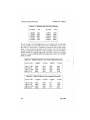
Tables 2-2 and 2-3 contain the scale and offset values (in hex and
decimal) to map a 2200 by 2200 Summagraphics tablet to the Q300,
Q400 and 0500.
Table 2-2. Tablet-To-Screen Conversions (Hexadecimal)
Screen
Size
1024 by 768
736 by 552
1280 by 1024
640 by 512
X-Offset
X-Scale
Y-Offset
Y-Scale
0000
0000
0000
0000
0072
055A
094E
04A7
02FF
0227
03FF
01FF
FA6C
F6FF
F890
FC49
Table 2-3. Tablet-To-Screen Conversbns (Decimal)
Screen
Size
1024 by 768
736 by 552
1280 by 1024
640 by 512
2-1B
X-Offset
X-Scale
Y-Offset
Y-Scale
0000
0000
0000
0000
1906
1370
2382
1191
767
511
1023
511
-1424
-1025
-1904
-951
July, 19B4
GRAFIN2 User's Manual
GRAFIN2 Command Dictionary
Example: To map a 2200 by 2200 tablet to a 736 by 552 screen:
4A 20
4Ah must precede all GRAFIN2 commands
00 00
X-Offset = OOOOh
5A 05
X-Scale = 055Ah
27 02
Y-Offset = 0227h
FF F6
Y-Scale = F6FFh
Related Commands:
INIT GRAFIN2
SET SCREEN SIZE
SET TABLET SIZE
October. 1904
GRAF1N2 User s Manual
GRAFIN2 Command Dictionary
SET Q MODE -- Sets button-detect and data-reporting modes.
(Event-Queue Command)
Hex: 41 detect-byte
Decimal: 65 detect-byte
report-byte
report-byte
Arguments: 2 bytes -- detect-byte = type of b u t t o n edge t h a t constitutes an event; report-byte = whether t a b l e t or screen coordinates are reported to the host.
Bytes Returned: None
Description: SET Q MODE determines which b u t t o n edge(s) are
detected and selects whether coordinates are r e p o r t e d as screen
or tablet coordinates. Only t h e lower two bits of t h e d e t e c t byte are
significant; only t h e lowest bit of the report b y t e is significant. All
other bits are reserved for f u t u r e use and should be set to zero.
Detect-byte values:
0 = level mode (events are recorded while a b u t t o n is held down
and the coordinates change)
1 = leading edge mode (button pushed)
2 - trailing edge mode (button released)
3 = both edge mode (two events — button pushed and released)
The default for INIT GRAFIN2 is leading edge d e t e c t i o n (value 1).
Report-byte
values:
0 = reports in
tablet coordinates
1 = reports in screen coordinates
The default for INIT GRAFIN2 is screen coordinates (value 1).
2-20
July. 1964
GRAFIN2 User's Manual
Example:
4A 41
00 01
GRAFIN2 Command Dictionary
4Ah m u s t precede all GRAFIN2 commands
Selects level button input a n d screen coordinates.
Related Commands:
INIT GRAFIN2
READ CURRENT POSITION
READ Q
READ Q AND WAIT
July, 1984
2-21
GKAFIN2 Command Dictionary
GRAF1N2 User's Manual
SET SCREEN SIZE -- Sets screen size for mapping.
(Environment Command)
Hex: 11 screenwidth
1 1 1 1 C»J
1 "7
1 f
Arguments:
screenheight
screenheight
pn^/i/TMnnV/f^
CT'Vrt/TM lh rtl f
It J l / I O t > ( W l/C, t/ty / L,l>
J L i I C & l l / \JU
4 bytes — screenwidth
= low-height, high-height
= low-width,
high-width;
Bytes Returned: None
Description: SET SCREEN SIZE maps the default tablet size to the
screen size specified in the arguments. The default tablet size is
2200 by 2200 pixels. (The tablet size can be changed with SET TABLET SIZE. If you need to change both tablet and screen sizes, issue both commands.)
The bounding box for clip or wrap mode is set t o the full screen
SET SCREEN SIZE does not change the default values used by INIT
GRAFIN2.
Example:
4A 11
00 05
00 04
4A m u s t precede all GRAFIN2 c o m m a n d s
screenwidth = 1280 (500h)
screenheight = 1024 (400h)
Related Commands:
INIT GRAFIN2
SET OFFSET/SCALE
SET TABLET SIZE
2-22
October, 1984
GRAF1N2 User's Manual
GRAF1N2 Command Dictionary
SET TABLET SIZE -- Sets tablet size for mapping.
(Environment Command)
Hex: 12 tabletwidth
Decimal: 18
tabletheight
tabletwidth
tabletheight
Arguments: 4 bytes — tabletwidth
bletheight = low-height, high-height
= low-width, high-width; ta-
Bytes Returned. None
Description: SET TABLET SIZE maps the t a b l e t size specified in the
arguments to the default screen size. The default screen size is
1024 by 768 pixels. (The screen size c a n be changed with SET
SCREEN SIZE. If you need to change both tablet and screen sizes,
issue both commands.)
SET TABLET SIZE does not change the default values used by INIT
GRAFIN2.
Example:
4A 12
00 04
00 04
4A m u s t precede all GRAFIN2 commands
tabletwidth = 1024 (400h)
tabletheight = 1024 (400h)
Related Commands:
INIT GRAFIN2
SET OFFSET/SCALE
SET SCREEN SIZE
October. 1984
2-23
GKAFIN2 Command Dictionary
GRAF1N2 User's Manual
SET WRAP MODE — Sets wrap-around mode for cursor tracking.
(Environment Command)
Hex: 21
comers
Decimal: 33
comers
Arguments: 8 bytes — comers
low-x2, high-x 2 , low-y2, high-y 2
= low-x1? high-x^ low-y^ high-y^
Bytes Returned: None
Description: SET WRAP MODE turns on wrap mode and defines the
diagonal corners of the bounding box. The coordinates of the
bounding box are always screen coordinates. If you move the
mouse beyond the area defined by the bounding box, the cursor
"wraps around" the boundary and r e a p p e a r s on t h e opposite side of
the bounding box. Refer to Figure 1-2.
Example
4 A 22
64 00
32 00
2C01
C8 00
4Ah must precede all GRAFIN2 commands
Xx = 64h
Y1 = 32h
X2 = lSCh
Y2 = C8h
Related Command:
SET CLIP MODE
2-24
October, 1984
GRAF1N2 User's Manual
GRAF1N2 Command Dictionary
SKETCH — Turns on sketching mode.
(Cursor-Tracking Command)
Hex 34
Decimal: 52
Arguments. None
Bytes Returned: None
Description: SKETCH is used to make f r e e f o r m drawings on the
screen. SKETCH draws in the currently-selected Omega color while
any button is held down on the mouse. Use the Omega SETCOL
command to change color while drawing.
SKETCH uses the crosshair cursor. While displayed, the cursor
tracks the mouse. The cursor remains on t h e screen until removed
by INIT GRAFIN2 or CURSOR OFF.
Button events are entered in the event queue as defined by the SET
Q MODE command.
Related Commands:
CURSOR OFF
CURSOR ON
SET CURSOR SIZE
SET Q MODE
October. 1984
2-25
GKAFIN2 Command Dictionary
GRAF1N2 User's Manual
WRITE TABLET — Sends initialization bytes to t a b l e t or mouse.
(Environment Command)
Hex: 24 init-bytes
IB
Decimal: 36 init-bytes
27
Arguments: init-bytes = device-dependent b y t e s to initialize special functions of the tablet. Argument is t e r m i n a t e d by an ASCII
escape (lBh).
Bytes Returned: None
Description: WRITE TABLET allows you to send initialization bytes
to the tablet, for example, to change the sampling rate. (Refer to
the manual of your tablet for the appropriate bytes.) In most
cases, you will not need this command. The c o m m a n d is terminated by an ASCII "escape" code (lBh).
Related Commands: None
2-26
October, 1984
Chapter 3
WRITING CUSTOMIZED GRAFIN2 COMMANDS
This chapter shows by example how to write customized GRAFIN2
commands using the Metheus version of FORTH1. In this chapter
we assume that you are an experienced programmer and that you
want to expand the functionality provided by GRAFIN2. If the existing GRAFIN2 commands meet your needs, you do not have to read
this chapter.
The chapter contains three sections:
o FORTH Fundamentals
o Command Examples
o GRAFIN2 Subroutines, Variables, and Pointers
The first part, "FORTH Fundamentals", introduces FORTH with some
simple examples. The second section, "Command Examples", contains examples with comments. The section shows you the implementation of the Rubberband Line cursor, the Sketch cursor a
"TV" cursor, and some grid-drawing routines. The examples ere
intended as a model for writing your own commands. The last section, "GRAFIN2 Subroutines, Variables, and Pointers", lists the
predefined FORTH routines and variables used by GRAFIN2.
GRAFIN2 is written in the Metheus version of FORTH. Appendix C is
a summary of Metheus FORTH. You should refer to the FORTH
reference manuals listed in the Preface for detailed information
about FORTH.
FORTH FUNDAMENTAL
FORTH is a stack based, interpreted language. FORTH evaluates
expressions by placing values on the evaluation stack, applying
operators to these values, then leaving the result on the stack or
saving the result away. (The evaluation stack is very similar to the
stack used by "Reverse Polish Notation" calculators.)
J
FORTH is a registered trademark of FORTH, Inc.
October. 1984
Writing Customized GRAFTN2 Commands
GRAFTN2 Users Manual
Commands are built up from subroutines which are, in turn, built
from the FORTH core words and Omega instructions. Data is
pushed on the stack in the reverse order of execution; the stack is
"last in, first out".
Definition of Terms
Table 3-1 contains t e r m s used in the discussions and examples t h a t
follow:
Table 3-1. FORTH Terminology
stack
The FORTH evaluation stack. FORTH uses this stack
for storing intermediate results. (FORTH also
has a return stack used for subroutine nesting
which GRAFIN2 does not use.)
TOS
Top Of Stack. The top word on t h e stack.
n l r\2 n3 n4...
One way to describe the stack: n l is the TOS, n2 is t h e
second word on the stack, n3 t h e word below that, ej
"abed..."
Another way to describe the stack: "abed..." represents words on the stack. The right-most c h a r a c t e r
(in this case, "d") is the TOS.
coordinate
Two numbers, X and Y, t h a t r e p r e s e n t a point on the
screen. These must always be positive numbers.
When pushed on the stack, X is always on top of Y.
LSB
Least Significant Bit (in some contexts, Byte).
Using the Stack
Figure 3-1 illustrates typical use of the stack. In this case, do A B + C, defining the variables and leaving the result in A.
NOTE
In this and all examples, the numbers appearing in the leftmost column are ONLY for the discussion of the example and
are NOT part of the FORTH input.
3-2
October, 19B4
GRAFTN2 Users Manual
1)
2)
3)
4)
5)
6)
?)
Writing Customized GRAFIN2 Commands
0 Var A
2 Var B
3 Yar C
B@
C@
+
A !
(
(
(
(
(
(
(
declare variable A )
declare B )
declare C )
move B t o the stack )
move C t o the stack )
add B and C together
save result in A )
Figure 3-1. Typical Stack Usage
Figure 3-1 illustrates a very simple stack operation. The first t h r e e
lines allocate t h r e e variables and give t h e m initial values of 0, 2,
and 3. Lines 4 and 5 move B and C to the s t a c k (C is the TOS). Line
6 adds t h e m together, leaving the result on the stack, and line 7
saves the result in A.
NOTE
All keywords (tokens) are separated by spaces or tabs. In
Metheus FORTH, tokens differ by length and by the first t h r e e
characters. Case is not considered; lower case is converted to
upper case. ('There" and "theory" differ in length, but "treat"
and "trees" are considered identical.) Comments are within
parentheses. Be sure to include the right parenthesis.
Extending FORTH With Subroutines
Because FORTH is a threaded, interpreted language, it is very easy
to extend t h e language by defining new subroutines. Metheus provides some subroutines for use with GRAFIN2; these are discussed
in the last section of this chapter. Once a routine is defined, it can
be called by other routines the same way FORTH core words or
previously-defined routines arc called. (The Metheus FORTH "core
words" are covered in Appendix C.)
Figure 3-2 shows a subroutine that finds the sum of the n u m b e r s 1
through 7.
October, 1984
3-2b
Writing Customized GRAFTN2 Commands
1)
2)
3)
41
5)
6)
decimal
: sum?
0
8 1 do
I
8)
;
?)
'
+
loop
GRAF1N2 Users Manual
( set base 10 )
( define a routine n a m e d 'sum7' )
( i n i t the accumulator )
( s t a r t at 1, count till we r e a c h 8 )
( get the c u r r e n t iteration c o u n t )
( add it to our a c c u m u l a t o r )
( bump the iteration count, exit if 8 )
( end definition of routine 'sum7' )
Figure 3-2. "Sum7" Subroutine
This summing example illustrates the construction of a simple subroutine. The first line sets the radix of the numbers, in this case,
decimal. Line 2 begins the definition of the routine "sum7' r . Line 3
pushes a 0 on the stack; this will be our accumulator. Line 4
pushes the p a r a m e t e r s of the loop onto the stack and begins the
Do ... Loop. The Do ... Loop construction is used to iterate through
a sequence of numbers. The p a r a m e t e r s of t h e loop (1 and 8) are
popped from the stack. The "I" and "+" in t h e fifth and sixth lines/
get the current iteration count and add it to the accumulator.^
Line 7 ends the Do ... Loop, and line 8 ends t h e definition of ,r sum7' r .
The routine "sum7" exits with the result left on the stack. We allocated no variables since the result would be left on the stack. The
code in Figure 3-3 executes "sum7" and saves its result in the variable A (which was defined in a previous example):
1)
2)
sum7
A!
( execute t h e routine )
( save the result in A )
Figure 3-3. Executing the ,r Sum7" Routine
By defining this routine, we have now extended the language to
include a function t h a t r e t u r n s trie sum of the first seven numbers.
October, 1984
GRAFTN2 Users Manual
Writing Customized GRAFIN2 Commands
Implementing the MINMAX Routine
Figure 3-4 shows the implementation of a GRAFIN2 subroutine,
minmax. Minmax sorts the top two values on the stack by size
NOTE
In discussing this and the remaining examples, the GRAFIN2
subroutines are referenced in boldface, and the variables and
pointers are referenced in italics.
The last section of this
chapter lists the GRAFIN2 subroutines, variables, and pointers.
1)
2)
3)
4)
5)
6)
7)
: minmax
over over
>
if
swap
then
;
(
(
(
(
(
(
(
define the routine )
copy the two top items on the stack )
compare the 2 numbers, replace with T/F
test if n2 is g r e a t e r t h a n n l )
reverse the order )
end of If s t a t e m e n t )
exit with larger n u m b e r on TOS)
Figure 3-4. Implementing the "Minmax" Routine
Minmax expects two numbers on the stack, and when it exits, the
larger number is on the top of stack. The first line s t a r t s the
definition of minmax. Line 2 copies the two numbers on the stack
so t h a t we now have four numbers on t h e stack. (If the values were
"ab", the stack now contains "abab".) The ">" in line 3 compares
the top two numbers and replaces t h e m with a True/False flag: a 0
if n2 was less than nl, else a 1. (In FORTH, 0 is false, non-zero is
true.) The stack now contains either "abO" o r "abl". The "if" statement in line 4 pops the T/F flag left by t h e ">" operator. If the
second number was bigger, line 5 swaps t h e two numbers left, oti
the stack. Line 6 ends the "if" s t a t e m e n t , and line 7 ends the
definition of minmax.
Learning FORTH
Now t h a t you have seen some simple examples of FORTH, you may
want to try it yourself. There are two ways t o learn FORTH on your
Omega system. The first method disables t h e GRAFIN2 firmware
October, 1984
3-2b
Writing Customized GRAF1N2 Commands
GRAFTN2 Users Manual
and allows you to directly access the FORTH i n t e r p r e t e r on the
GRAFIN2 card. Routines developed this way are lost when you
enable GRAFIN2 again. This method is intended only for learning
FORTH.
The second method downloads routines to t h e FORTH i n t e r p r e t e r
with one of the GRAFIN2 FORTH commands: opcodes 50h, 51h, 52h,
or 53h. (The GRAFIN2 FORTH commands, like all GRAFIN2 commands, must be preceded by opcode 4Ah.) Your routines are stored
in the "user-dictionary".
NOTE
The stack and the user-dictionary share approximately 1200
bytes of memory on the GRAFIN2 card. The stack and dictionary are located at opposite ends of m e m o r y and each "grows"
toward the middle. If you define too m a n y routines, the stack
area may become so small t h a t the system crashes.
METHOD ONE - HARDWARE DIRECT
The first method of learning FORTH requires you to remove the
cover of your Omega and t u r n off switch 7 of the data-transfer
switch on the GRAFIN2 card. (See Appendix A for instructions.
Refer to Figure A-3 for the location of t h e switch.) Switch 7 OFF disables the normal GRAFIN2 firmware and allows you to communicate
directly with the FORTH interpreter on the GRAFIN2 card. You can
plug your terminal into tablet port J4 on t h e back of the Omega.
Be sure the baud r a t e of your terminal m a t c h e s the baud rate of
the Omega.
With switch 7 OFF, all input from J4 goes directly to the FORTH
interpreter. A "control C" will usually break you out of a FORTH
program and r e t u r n control to the i n t e r p r e t e r . If your program
completely crashes, you can regain control by turning the Omega
off and back on. Be sure to t u r n switch 7 ON when you are don^
playing with FORTH, otherwise the Omega will not boot up.
CAUTION
Be sure to replace the cover of the Omega a f t e r setting the
switch or you may damage the circuit board. The Omega's
cooling system requires the cover to be in place.
3-6
October, 1984
GRAFIN2 Users Manual
Writing Customized GRAFIN2 Commands
METHOD TWO - DOWNLOADING
You can download routines to the FORTH i n t e r p r e t e r with the
GRAFIN2 firmware. User-defined routines execute before the routines located in the firmware. Therefore, if you write a new version
of an existing command, your command executes instead of the
original. (The original is not affected).
Entering opcodes 50h, 51h, or 52h p e r f o r m s t h r e e functions:
removes the cursor (if it was visible), s e t s the cursor type to
crosshair, and opens a channel to the host. FORTH input is terminated by an escape (lBh). Opcode 53h, Forget Words, is used to
delete all user-defined entries from the FORTH dictionary. You can
also use the FORTH "forget" routine to delete specific routines.
Table 3-2 summarizes the GRAFIN2 c o m m a n d s t h a t call FORTH.
TABLE 3-2. - GRAFIN2 FORTH COMMANDS
Opcode
Meaning
50h
Comm mode. Used to download debugged code. The error count is reset to zero when FORTH is invoked. Nothing is displayed on the Omega screen.
51h
Error mode. Used to download code t h a t may contain
errors. The error count is reset t o zero when FORTH is
invoked. Errors are displayed on the Omega screen.
When leaving FORTH, the error count is displayed.
52h
Text mode. Used to download code t h a t may contain errors. The error count is r e s e t to z e r o when FORTH is invoked. All FORTH code (except comments) is displayed
on the Omega screen. When leaving FORTH, the error
count is displayed.
53h
Forget Words. Used to delete all user-defined commands
from the dictionary. (See also t h e FORTH "forget" routine.)
October, 1964
3-7
Writing Customized GRAF1N2 Commands
GRAFTN2 Users Manual
COMMAND EXAMPLES
This section contains examples that show t h e implementation of
t h r e e cursors and some grid-drawing routines.
Writing Custom Cursors
In general, you need to create t h r e e routines t o draw a custom cursor:
o a cursor-erasing routine
o a curs or-drawing routine
o an installation routine
The three routines are linked by the pointer variables ccdown and
ccup. The installation routine puts the address of the cursorerasing routine in ccdown and the address of the cursor-drawing
routine in ccup.
The routine remove uses the erasing routine pointed to by ccdown
to erase the cursor. In addition, remove pushes the c u r r e n t cursor,
coordinates on the stack before using ccdown.
The routine new uses the drawing routine pointed to by ccup to
draw the new cursor. New pushes the c u r r e n t cursor coordinates
on the stack before using ccup.
The installation routine needs to erase any cursor t h a t may
currently be visible by calling remove, set ccdown and ccup, and
draw the new cursor with the new routine.
1)
2)
3)
4)
5)
: U35
remove
" Draw ccup !
" Erase ccdown !
new
(
(
(
(
(
(
GRAFIN2 names begin with 'U'
removes a cursor if visible )
installs Draw )
installs Erase )
draws the new cursor )
end definition of U35 )
Figure 3-5. An Installation Routine
Figure 3-b illustrates an installation routine that defines a new
3-56
October, 1984
GRAFTN2 Users Manual
Writing Customized GRAFIN2 Commands
cursor as opcode 35h. (Assume t h a t we have previously defined the
"Draw" and "Erase" routines.) The first line s t a r t s the definition of
the routine. By convention, all GRAFIN2 commands are named
"Unn", where nn is a hex number. (To execute the command, you
would enter "4A?m".) Remove, in line 2, pushes the cursor's coordinates on the stack and removes the c u r r e n t cursor if one is visible.
(At this point, ccdown contains the last cursor-erasing routine
used.) Line 3 takes the address of Draw and stores it in the pointer
variable ccup. Likewise, line 4 puts the address of Erase in ccdown.
New, in line 5 causes the new cursor to be drawn. When new executes, it places the current coordinates on the stack (X on top, Y
as the second word), then calls the Draw routine. Likewise, remove
places the c u r r e n t coordinates on the s t a c k t h e n calls the Erase
routine.
After the -Draw or Erase routine executes, t h e stack contains the
Omega instructions placed on it by the routines. The instructions
on the stack are executed ("unloaded") by t h e sexec (Stack EXECution) routine. The GRAFIN2 firmware automatically calls new,
remove, and sexec at the 60Hz r e f r e s h r a t e until it receives
another command.
Implementing the Rubberband Line Cursor
The Rubberband Line cursor is supplied in the GRAFIN2 firmware.
The Rubberband Line cursor draws a complement vector between
an anchor point and the cursor's location. Figure 3-6 shows the
implementation of the Rubberband l i n e cursor.
The Rubberband Line command contains t h r e e subroutines:
anchor, rlcomp, and U32. Before defining t h e subroutines, we set
hex as the radix and define two variables, xanchor and yanchor.
These variables hold the location of the anchor point for the complement vector. The routine anchor in line 4 reads an XY coordinate from the host and saves it in xanchor a n d yanchor.
line 8 begins the definition of the rlcomp (Rubber Line COMPute)
routine. Rlcomp pushes the data and opcodes needed to draw a
complement mode vector from the anchor location to the c u r r e n t
tablet position. Rlcomp is entered with t h e current XY cursor
October, 1984
3-2b
Writing Customized GRAF1N2 Commands
GRAFTN2 Users Manual
1) hex
( set hexadecimal f o r m a t for n u m b e r s )
2) 0 var xanchor
3) 0 var yanchor
( define anchor points )
4)
5)
6)
7)
anchor
( routine to set anchor point from host data )
wgethost xanchor !
wgethost yanchor !
( routine to push the complement vector d a t a to the stack )
( begin definition of rubberline compute )
8) :: rlcomp
( push compdr )
0172
9)
( get X to TOS, t h e n Y )
10) rrot
( push mov P i + flag )
11) 0752
( get the anchor points )
12) yanchor £l> xanchor @
( push mov P2 + flag )
13) 0753
( sets a solid line )
14) 68 0250
( end definition of rlcomp )
15) ;
( r u b b e r line cursor )
16) : U32
17) remove
18) " rlcomp dup ccdown ! ccup ! ( install new routine )
19) anchor
20) new
21)
Figure 3-6. Implementing the Rubberband Line Cursor
position on the stack.
Since we are pushing Omega instructions on the stack, the first
actions are the last items pushed on the stack. For rlcomp, the
last action is the complement draw. Thus t h e first Omega opcode
that we push is t h e COMPDR instruction in line 9.
After pushing the COMPDR opcode, we move t h e XY on top of it
3-10
October, 1984
GRAFTN2 Users Manual
Writing Customized GRAFIN2 Commands
using the RROT command. RROT r o t a t e s the top t h r e e stack
entries so t h a t n l becomes n3. (If the stack contained "abc", it now
contains "cab".) This leaves X on top of the stack with Y beneath it.
Next we push the MOY P i opcode (0752h) t o the stack—its parameters are the X and Y already on the stack. In line 12, we retrieve
the anchor points from yanchor and xanchor (the X coordinate will
be on top), then push the MOY P2 instruction in line 13. Finally we
push the Omega PATTERN instruction and d a t a in line 14 to set a
solid line.
The routine U32 installs the rubber line cursor. In line 17 it calls
remove to erase any currently drawn cursor. In line 18 it gets the
address of rlcomp to the stack, duplicates it, then saves it in ccup
and ccdown. It then calls anchor in line 19 to get the XY coordinates of the anchor location from the host computer. Finally, it
calls new in line 20 to draw the new cursor.
Once the stack contains the instructions and data, the routines
sexec, new, and remove are automatically invoked (at the 60Hz
refresh rate). After this, the routine rlcomp is called automatically
whenever the system needs to update t h e cursor position.
Stack Management With SEXEC
Since the stack uses 16-bit numbers, the u p p e r byte of each Omega
opcode on the stack tells sexec the location and size of the
opcode's parameters. Note that only the low byte of the opcode is
sent to the Omega. The upper byte is used f o r stack management.
If the upper byte is 0, the next word on the stack points to a block
of data to be sent to the Omega. The first word of the block is the
byte count (16 bits), and the following bytes are data.
If the upper byte is non-zero, the p a r a m e t e r s for the opcode are on
the stack. The upper byte specifies how m a n y p a r a m e t e r s are on
the stack, which of them are bytes, and which of t h e m are words.
Only seven p a r a m e t e r s can be passed in this manner.
October, 1984
3-2b
Writing Customized GRAF1N2 Commands
GRAFTN2 Users Manual
The algorithm (in "C") for making the u p p e r byte is:
int upper_byte ;
upper_byte = 1 ;
/* check all p a r a m e t e r s for size */
for (i ~~ number_params; i > 0; i—) [
/ * we have a parameter, shift upper_byte up 1 */
upper_byte *= 2 ;
/ * now set the LSB to 1 if a word p a r a m e t e r */
if (param[i] == WORD)
upper_byte + = 1 ;
Here is how sexec interprets the upper byte. When the upper byte
equals 1, there are no p a r a m e t e r s left on t h e stack. When the
upper byte is greater than 1, the LSB of the u p p e r byte represents
the next p a r a m e t e r of the opcode. If it is 0, the p a r a m e t e r is a
byte, if a 1 the p a r a m e t e r is a word. The firmware t h e n performs a
right shift and tests if the upper byte is g r e a t e r t h a n 1. When t h e
upper byte is equal to 1, t h e r e are no more p a r a m e t e r s for t h a t
opcode on the stack. Some typical u p p e r b y t e s are:
Opcode
6lh
72h
52h
4Eh
70h
- Draw
- Compdr
- Mov P1
- Mov Color
- Pixblt
Upper^Byte
Olh
Olh
07h
02h
OBh
Composite
Opcode
^
016lh
0172h
0752h
024Eh
0B70h
The byte/word distinction is important. Since t h e stack is allocated
in words, sexec m u s t know which stack e n t r i e s are byte parameters, which are words, and which are opcodes. The stack always
pops words; when a byte is sent, the upper byte is thrown away.
Sexec stops when it sees a 0 opcode. This 0 is preloaded at the bottom of the stack by the GRAFIN2 firmware.
Implementing the Sketch Cursor
The Sketch cursor (opcode 34h) leaves a trail behind the cursor
during the time a b u t t o n is pushed on the mouse. Figure 3-7 illustrates the implementation of the Sketch cursor.
3-12
October, 1984
GRAFIN2 Users Manual
Writing Customized GRAFIN2 Commands
Sketch contains two routines; inkup a n d U34. U34 uses the
xhair_set routine instead of remove to e r a s e the previous cursor.
To implement Sketch, we first set hexadecimal as the c u r r e n t radix
and define the variables xanchor and yanchor.
Next we create a routine inkup t h a t draws t h e cursor's trail in ihe
current Omega drawing color while a b u t t o n is pressed. Inkup is
1) hex
( set hexadecimal f o r m a t for n u m b e r s )
2) 0 var xanchor
3) 0 var yanchor
( initialize our variables )
( compute
4) : inkup
5)
cxhair
6)
epos toscreen
7)
button if
cursor routine - ink lines if button pressed )
8)
9)
10)
11)
( compute the Xhair cursor )
( get tablet and convert to screen coords )
( get the button s t a t u s )
( if a button is pressed )
0161 rrot ( push draw; rotate XY to TOS )
0753
( mov P 2 )
2over yanchor @ swap yanchor !
( store Y in yanchor )
2over xanchor @ swap xanchor !
( store X in xanchor )
0752
(mov P I )
68 0250
( set solid line )
12)
13)
14)
else
15)
xanchor ! yanchor !
16)
then
i?) ;
( update l a s t position )
( sketch in c u r r e n t drawing color while a button is pressed )
18) : U34
19)
xhair_set
( set crosshair cursor )
20)
" inkup ccup ! ( install new routine )
21)
new
23) ;
Figure 3-7. Implementing the S k e t c h Cursor
October, 1964
3-13
Writing Customized GRAFIN2 Commands
GRAFIN2 Users Manual
called with XY coordinates on the stack. Line 5 calls the routine
cxhair. Cxhair replaces the coordinates with the appropriate
Omega moving and drawing instructions to c r e a t e a complemented
crosshair cursor. The "epos toscreen" in line 6 takes the c u r r e n t
tablet position and converts it to screen coordinates. Line 7
checks the button status. If a button is being pressed, line 8
("0161 rrot") pushes an Omega DRAW instruction, t h e n rotates the
top t h r e e stack entries so t h a t the X and Y are back on the TOS.
Lines 8 through 13 draw a vector from the last cursor position to
the current position. The "0753" in line 9 pushes MOV P2 to the
stack; it will use the X and Y on the stack as data. Lines 10 and 11
move the previous cursor position to the stack and store the
c u r r e n t position in xanchor and yanchor. Then in line 12, MOV P i is
pushed to the stack. The last line of the "if" s t a t e m e n t pushes an
Omega PATTERN instruction and data to set a solid line.
The "else" s t a t e m e n t in line 14 updates the c u r s o r ' s position when
no button was pressed.
Routine U34 installs the SKETCH cursor. Xhair_set removes the old,
cursor and sets ccup and ccdown to the a d d r e s s of cxhair. Line 20, \
" " inkup ccup ! ", places the address of inkup in ccup. New
pushes the c u r r e n t coordinates to the stack and calls the routine
whose address is in ccup (inkup).
Implementing the TV Cursor
The "TV" cursor (opcode 35h) is not supplied with the standard
GRAFIN2 firmware. The command draws a small rectangle on the
screen to be the "TV receiver", and the cursor acts as a roving
camera. The command performs a block t r a n s f e r of the information the cursor "sees" to the "receiver" area. (It is helpful to have
something on the Omega screen for the cursor to "see" when you
invoke the TV cursor.)
The "TV" cursor defines two routines: bltup and U35. But first we
set the c u r r e n t radix to hex and define two variables, xsave and
ysave.
The bltup routine performs a block t r a n s f e r of the information
^-14
October, 1984
GRAFTN2 Users Manual
Writing Customized GRAFIN2 Commands
1) hex
( set hexadecimal format for n u m b e r s )
2) 0 var xsave
3) 0 var ysave
( define our variables )
I
( routine to compute the cursor-drawing commands )
4) : bltup
5)
over over
( copy the X Y )
6)
xsave ! ysave !
( save the X Y away for now )
?)
cxhair
( compute the cross hair )
8)
0 80 80 0B70
( data for the p i x b l t )
9)
IFF dup 0753
( mov P2, pixblt destination )
10) ysave @ xsave @ 0752
( mov P i , pixblt source )
11) ;
( install this as a new
12) : U35
13) remove
14)
" bltup ccup !
15)
" cxhair ccdown !
16)
0163
17)
OFF 024E
18)
1FE dup 0752
19)
280 dup 0753
20)
new
21) ;
H
I
cursor, name it U35 )
( remove a c u r s o r if visible )
(install cursor draw routine )
( install cursor e r a s e routine )
( draw rectangle around destination )
( set color 255 - white )
( mov P1 )
( mov P2 )
( draw a new c u r s o r )
Figure 3-8. Implementing the TV Cursor
"seen" by the cursor to the "receiver" area on the Omega screen.
Bltup is called with an XY coordinate on the stack. Lines 5 and 6,
("over over" and "xsave ! ysave !"), copy the coordinates and save
them away in the variables xsave and ysave for temporary storage.
Line 7 calls cxhair, which replaces the XY with the commands
needed to draw a complement mode cross-hair cursor on the
stack. In line 8, we push the Omega PIXBLT instruction to the
stack: the opcode and three parameters. Note the order t h a t we
push the p a r a m e t e r s and opcode. We now p u s h the MOV P2 instruction to the stack in line 9 with the fixed a d d r e s s of (lFFh,lFFh).
This is the destination of PIXBLT instruction. Finally, in line 10, we
October, 1984
3-2b
Writing Customized GRAF1N2 Commands
GRAFTN2 Users Manual
retrieve the cursor position from xsave and ysave
MOV PI (the source of the PIXBLT).
and use it with
When the stack is unloaded (via sexec), the c o m m a n d s sent to the
Omega are:
1) MOV P i to c u r r e n t tablet position
2) MOV P2 to (lFFh, lFFh)
3) PIXBLT a rectangle from P i to P2
4) Draw a cross-hair cursor.
U35 is the installation routine. First, the c u r s o r is removed f r o m
the screen by remove in line 13. We then install bltup as the
cursor-drawing routine by placing the address of bltup in the variable ccup. vVhen we examine bltup we see t h a t it uses the crosshair cursor routine cxhair. Because of this, we install cxhair as the
cursor-erasing routine. Next, in line 16, we draw a box around the
"TV receiver." Since the stack is unloaded in reverse order, the
first thing we push is the Omega RECTI instruction (outline box).
We then set the drawing color to white (color 255). Next we push
coordinates for the two corners of the box with t h e appropriate
MOV PI and MOV P2 instructions in lines 18 a n d 19. One corner is
at (lFEh, lFEh) and the other is at (280h,280h). Finally, we call new(
in line 20 to draw the cursor the first time. New will call bltup to
draw the cursor.
Before the next cursor is drawn, the previous cursor must be
removed. Since t h e routine cxhair was installed as t h e erase routine, the GRAFIN2 firmware will automatically invoke cxhair a f t e r
bltup so t h a t the crosshair-cursor-erase instructions and data are
on t h e TOS. Thus the previous cursor is erased before t h e next one
is drawn since the stack is unloaded top to bottom.
Implementing Grid and Grid-Drawing Routines
The final command example, shown in Figure 3-9, contains t h r e e
grid routines:
U18 — Followed by one byte each of X spacing and Y spacing
to set grid size. The cursor is snapped to the grid.
U19 ~ Turns off snapping the cursor to t h e grid.
3-16
October, 1984
GRAFTN2 Users Manual
Writing Customized GRAFIN2 Commands
U81 — Followed by one byte each of X spacing and Y spacing
to set grid size. Draws a grid on t h e screen in the c u r r e n t
Omega drawing color. (Cursor is not snapped to this ^rid).
The size of the grid (for either U18 or U81) is given as one byte of X
spacing and one byte of Y spacing, and s t o r e d in xgrid and ygrid,
defined in lines 2 and 3.
"Snapping" the cursor to the grid means t h a t the cursor moves in
discrete jumps. The jump size is specified by the XY spacing.
Snapping uses a feature called filtering. One example of filtering is
shown in the GRID routine in Figure 3-9. This routine i n t e r c e p t s
the tablet data and modifies it before the GRAFIN2 firmware draws
the cursor.
More importantly, you can write routines t h a t are unrelated to
graphics input! The routine U81, also shown in Figure 3-9, simply
draws a grid on the screen in the currently selected drawing color
The ability to download general-purpose routines to the FORTH
interpreter offers an efficient alternative to host resident software.
October, 1984
3-2b
Writing Customized GRAFTN2 Commands
GRAFIN2 Users Manual
1) hex
( set hexadecimal f o r m a t for numbers )
2) 0 var xgrid
3) 0 var ygrid
( declare 2 variables to hold the grid s p a c i n g )
4) 752 con p i
5) 753 con p2
6) 161 con draw
( constants for use in grid drawing routine )
( filter the XY on the stack so t h a t it is snapped to the grid )
7) : grid
( get 1/2 the xgrid value, add to X )
xgrid @ 2 / +
8)
dup xgrid @ mod 9)
( do the same for Y )
swap
10)
ygrid @ 2/ +
11)
dup ygrid @ mod 12)
( put X on TOS )
swap
13)
14)
<v
( turn grid on )
15) : U18
16)
remove
17)
hget xgrid !
1.8) hget ygrid !
19)
" grid uscaleat !
20)
ifon
( remove the cursor )
( init the X and Y grid spacing )
21) ;
( turn grid off )
22) : U19
remove
23)
" null uscaleat !
24)
ifon
25)
26)
Figure 3-9. Implementing Grid-Drawing Routines
3-lB
October, 1904
Writing Customized GRAFIN2 Commands
GRAFTN2 Users Manual
( draw a grid on the screen in current color )
27) : U81
28)
hget xgrid !
29)
hget ygrid !
30)
31)
32)
33)
34)
35)
( init the X and Y grid spacing )
swidth @ 0 do
draw
0 1 pi
sheight @ 1 p2
sexec drop
xgrid @ +loop
36)
sheight @ 0 do
37)
draw
38)
10 p i
39)
I swidth @ p2
40)
sexec drop
41)
ygrid @ +loop
42) ;
( draw vertical lines )
( draw horizontal lines )
Figure 3-9. (Cont.) Implementing Grid-Drawing Routines
GRAFIN2 SUBROUTINES, VARIABLES, AND POINTERS
This section contains subroutines, variables, and pointers used by
GRAFIN2. Entries are arranged alphabetically within each grouping. Variables and pointers are referenced by italics and subroutines by bold text.
GRAFIN2 Subroutines
anchor
Reads an XY coordinate from the host and initializes the variables xanchor and yanchor with the values.
bget
Gets a byte f r o m the Omega, fills leading zeros to 16 bits and
r e t u r n s that word as the TOS.
October, 1984
3-2b
Writing Customized GRAF1N2 Commands
GRAFTN2 Users Manual
bsend
Sends the lower byte of the TOS word to t h e Omega,
button
Returns the c u r r e n t button ID on the TOS. This word is 0 if no
buttons are pressed. The button ID format is tablet dependent.
clip
Clips the XY coordinates on the TOS so t h a t it is within the
c u r r e n t bounding box defined by hiXclip, LoXclip, hiYclip, and
to Yclip.
epos
Pushes the c u r r e n t tablet coordinates on t h e stack (X is TOS).
csend
Gets a byte f r o m the Omega and puts it on t h e stack,
cxhair
Uses the XY coordinates on the TOS to produce the appropriate
Omega move and draw instructions needed to create a complemented crosshair cursor. The XY are replaced on the stack by
the Omega instructions and data.
event
Moves a button from the event queue to t h e stack. If the event!
queue is empty, event p u t s a -1 on t h e stack, otherwise event
pushes a word with the button in the low byte (top of stack),
followed by a word of X coordinate, t h e n a word of Y coordinate.
(The X and Y a r e in tablet coordinates).
hcoord
Gets an XY coordinate f r o m the host c o m p u t e r and places it on
the stack. The host m u s t send four bytes: low_x, hL_x, low_y,
hi_y. The Omega must be ready to accept a n opcode.
hget
Gets a byte f r o m the host computer, fills leading zeros to 16
bits, and r e t u r n s that word as the TOS. The Omega must be
ready to accept an opcode.
hput
Sends the low byte of the TOS to the host computer, discarding
the high byte. The Omega m u s t be ready to accept an opcode.
3-20
October, 1984
GRAFTN2 Users Manual
Writing Customized GRAFIN2 Commands
if O i l
Redraws a cursor on the screen if remove erased one. If on
calls new to do this.
init
Removes the cursor, t h e n resets all variables to their power-up
state. (See INIT GRAFIN2, opcode lOh, in Chapter 2.) Userdefined routines are not affected,
minmax
Sorts the top two numbers on the stack so that the larger is on
the TOS and the smaller is beneath it.
new
Checks if a cursor is displayed on t h e screen. If not, new
pushes the current XY coordinates on t h e stack. It then computes the new cursor-drawing data and instructions by calling
the routine whose address is in ccup. New leaves the Omega
data and instructions on the stack. The stack contents are
later automatically sent to the Omega b y sexec.
null
Does nothing and is the default routine pointed to by uscaleat.
ppad
Sends the low byte from the TOS to the tablet devices,
qflush
Discards any data in the event queue,
remove
Checks if a cursor is displayed on t h e screen. If so, remove
pushes the cursor's XY position to the stack. It then removes
the cursor by calling the routine whose address is in ccdoum.
Remove then invokes sexec to send t h e instructions and data
stored on the stack to the Omega.
sexec
Pops instructions and data from the s t a c k and sends thern to
the Omega until a zero opcode is found. Sexec leaves the zero
on the stack and also r e t u r n s a garbage word on TOS. Sexec is
invoked automatically at 60Hz.
size_init
Uses the top two words on the stack t o r e s e t values used in
tablet-to-screen transformations and s c r e e n clipping. The TOS
is the screen width, t h e word beneath it is the screen height.
October, 1984
3-2b
Writing Customized GRAF1N2 Commands
Size_init sets
y off set
xoffset
yscale
zscale
swidth
shezght
GRAFTN2 Users Manual
variables:
twidth
t height
hiXcLip
LoXcLip
hiYclip
to Yclip
toscreen
Converts the XY coordinates on the TOS f r o m tablet coordinates to screen coordinates, using the c u r r e n t offsets and
scales. After conversion, a user-defined filter can be applied by
the routine pointed to by uscaleat.
Finally, the position is
clipped or wrapped by invoking the routine whose address is in
clpwrp.
wgethost
Gets a word f r o m the host computer and p u t s it on the stack.
The Omega m u s t be ready to accept an opcode. If the host
does not send a word, the Omega will hang and need to be
reset.
/
wputhost
Sends the word on the TOS to the host computer. The Omega
must be ready t o accept an opcode.
wrap
Wraps the XY coordinates on the TOS so t h a t t h e point is within
the current bounding box defined by hiXclip, loXclip, hiYclip,
and to Yclip.
wsend
Sends the top word on the stack to the Omega,
xfiiiit
Uses the variables swidth and twidth to calculate xscale and
xoffset, and sheight and theight to calculate yoffset and yscale.
The scale and offset values are used to convert tablet-to-screen
coordinates so that the full tablet size is mapped to the full
screen. (See SET OFFSET/SCALE, opcode 20h, in Chapter 2.)
xhair_set
Removes the cursor and installs the crosshair cursor as t h e
c u r r e n t cursor type by setting ccup and ccdown to t h e address
of cxhair.
3-22
October, 1984
GRAFIN2 Users Manual
Writing Customized GRAFIN2 Commands
Scaler Variables
cheight, cwidth
Two variables containing the height and width of the c u r r e n t
bounding box as set by SET WRAP MODE and SET CLIP MODE
(opcodes 2 l h and 22h). Also see size_init.
ecount
Tells how many button events are s t o r e d in the event queue (0
means empty).
hiXclip, hiYclip, LoXclip, loYclip
Four variables t h a t define the bounding box for the clip and
wrap routines. HiXclip > loXclip and hiYclip > loYclip, or you
will get unpredictable results. Also, cvuidth and cheight m u s t
be set so t h a t they agree with the bounding box. These variables are set by SET WRAP MODE and SET CLIP MODE (opcodes
2lh and 22h), and are also set by size_init.
swidth, sheight
Two variables containing the screen's width and height. They
are used in computing the tablet-to-screen conversion. They
are initially set to 1024 by 768. If this is not your screen size,
use SET SCREEN SIZE (opcode l l h ) to p u t the correct values
into these variables. See also routines size_init and xfinit.
sync on
Enables an Omega SYNC instruction between cursor draw and
erase when this variable is set to 1. (Most cursors look b e t t e r
with this variable set to l).
trig
Selects the trigger mode when a b u t t o n is put in the event
queue. See SET Q MODE, opcode 41h.
Trigger Flag
Mode
0
Level Mode
1
Leading Edge
2
Trailing Edge
3
Both Edges
twidth, theight
Two variables containing the tablet's width and height. They
are used by xfinit in calculating the tablet-to-screen conversion. They are initially set to 2200 by 2200 (Summa bit pad
size). If this is not your tablet size, you can use SET TABLET
SIZE (opcode I2h) to put the c o r r e c t values into these
October, 1964
3-23
Writing Customized GRAF1N2 Commands
GRAFTN2 Users Manual
variables. If you change these values, you m u s t call xfinit.
xanchor, yanchor
Two variables used only inside the cursor t r a c k i n g routines. If
you write a custom cursor, you can use t h e s e for t e m p o r a r y
storage.
xscale, xoffset, yscale, yoffset
Four variables containing the scale and offset values used to
transform the tablet coordinates to s c r e e n coordinates. (See
t h e SET OFFSET/SCALE (20h) command in Chapter 2 for their
format.) Also see size_init
Pointer Variables
These variables point to routines to execute.
ccup, ccdown
These variables are set with the addresses of t h e routines t h a t
draw and erase the cursor. Each routine is called with the
current cursor position on the stack (X on top). Each routine
replaces the coordinates with a set of Omega instructions. In
you need to install a routine t h a t does nothing in one of these
variables, r e m e m b e r that the routine m u s t drop two words (the
X and Y) from the stack.
clpwrp
Contains the address of either the clip routine or the wrap routine. You would typically set it by:
" wrap clpwrp !
or
" clip clpwrp !
scale at
Points to the routine that converts tablet coordinates to screen
coordinates for button-reporting. GRAFIN2 normally sets this
to " null (for tablet coordinates) or " toscreen (for screen
coordinates).
uscaleat
Points to a user-defined position-scaling routine. The routine is
called after the current position is converted f r o m tablet toscreen coordinates. After the routine is called, the result is
clipped or wrapped. This variable is normally set to " null and
3-24
October, 1984
GRAFTN2 Users Manual
Writing Customized GRAFIN2 Commands
can only be changed by a user-created GRAFIN2 command The
routine uscaleat points to is called with XY on the stack, and
must r e t u r n with an XY on the stack. Also see toscreen.
October, 1984
3-2b
APPENDIX A
GRAFIN2 INSTALLATION
This chapter explains how to install GRAFIN2 in your Omega system. The GRAFIN2 update package includes t h e GRAFIN2 board and
eight new PROMs for the Omega display controller board.
Specifically, the instructions in this c h a p t e r describe:
o
o
o
o
Position of the GRAFIN2 board
Replacing the microcode PROMs in t h e Omega display controller board
Selecting GRAFIN2 data rates
Connecting t h e graphics tablet
CAUTION
Only qualified service personnel should a t t e m p t any procedure
where the covers must be removed. Read and follow t h e installation instructions carefully. Failure t o properly install the
GRAFIN2 board or microcode PROMs could result in improper
operation or equipment damage to your Omega system.
(1) Unplug the Omega from the AC power source.
(2) Remove the top cover by removing the screws t h a t hold it in
place.
(3) Remove the interface board (and if you are upgrading f r o m
GRAFIN, also remove the GRAFIN board.) Figure A-l illustrates
the position of t h e interface and GRAFIN2/GRAFIN boards.
July. 1984
A-l
GRAFIN2 User's Manual
GRAFIN2 Installation
Controller Board
F-0080
Figure A-l. Position of t h e Interface and GRAFIN2 Boards
(4) Replace the Omega microcode PROMs. Figure A-2 illustrates
the location of the microcode PROMs for t h e £)300/fi400 and for
the Q500.. Note the a r r a n g e m e n t of the PROMs.
WARNING
Be sure t h a t each PROM is in t h e c o r r e c t socket and is
correctly oriented. Failure to install the PROMs correctly may
damage the PROMs and result in improper operation.
July, 1964
GRAF1N2 User's Manual
GRAFIN2 Installation
F-0079
Figure A-2. Installing the Omega Microcode PROMs
July. 1984
A-3
GRAFTN2 User's Manual
GRAF1N2 Installation
(5) Select GRAF.IN2 Data Rates. GRAFIN2 interface boards are set
at the factory for 9600 baud. If you need t o change this setting,
follow these instructions. Find the 8-position switch near the
center of the GRAFIN2 board. Four positions, numbered 1
through 4 in Figure A-3, select the t r a n s f e r rates. This figure
shows the default switch positions selecting 9600 baud.
<v
1 2 3 4 5 6 7 8
Off
Off
F-0014
Figure A-3. The GRAFIN2 Data-Transfer Switch
(6) Select t h e new baud r a t e f r o m Table A-l and set the switches
accordingly.
A-4
July. 1964
GRAFIN2 User's Manual
GRAFIN2 Installation
Table A-l. Data Rate Selection
Switch
1
2
Baud
Rate
Settings
3
4
unused
1
1
19.2K
0
1
9600
1
0
7200
0
0
4800
1
1
0
1
3600
0
1
0
1
2400
1
0
0
1
1800
0
0
0
1
1200
1
1
1
0
600
0
1
1
0
300
1
0
1
0
150
0
0
1
0
134.5
1
1
0
0
110
0
1
0
0
75
1
0
0
0
50
0
0
0
0
NOTE: 0=0ff, l=On
(7) Switch 5 determines resolution format. When set in the 0 (off)
position, the GTCO binary high-resolution f o r m a t is selected.
The 1 (on) position selects the Summagraphics Bit-Pad format.
July, 1964
A-5
GRAFIN2 User's Manual
GRAF1N2 Installation
(Refer to the tablet manual for compatibility information.) The
factory setting is 1, selecting the Summagraphics Bit-Pad format.
(8) Switches 6, 7, and 8 are reserved for f u t u r e use and should
remain as illustrated: switches 6 and 7 a r e on, and switch 8 is
off.
(9) After changing switch positions, replace boards as in Figure A1. Replace the top cover and the power cord.
(10)
Connect the input device to the Omega. Attach the input device to socket J4 on the back of the Omega. The pin arrangem e n t of the RS-232 connector is illustrated in Figure A-4.
o
•
•-jf
1
2
3
4
5
6
7
• 20
Ground
Transmit Data (to tablet)
Receive Data (from tablet)
RTS (Request to Send - always high)
CTS (Clear to Send - ignored)
DSR (Data Set Ready - ignored)
Ground
DTR (Data Terminal Ready - always high)
,
o
F-0082
Figure A-4. RS-232 Pin Configuration for GRAFIN2
A6
July, 1984
Appendix B
GRAFIN AND GRAFIN2 DIFFERENCES
GRAFIN2 differs from GRAFIN in the following ways:
(1) GRAFIN2 stores button hits in the b u t t o n event queue. GRAFIN
sends button hits to the host immediately (no event queue).
(2) GRAFIN2 returns six bytes of information about button hits;
GRAFIN returns five.
(3) GRAFIN2 allows a choice of four styles of cursor, plus varying
the size of the default crosshair cursor. GRAFIN supports only
the crosshair cursor.
(4) GRAFIN2 keeps the cursor on the screen unless taken down
explicitly with the INIT GRAFIN2 or CURSOR OFF commands.
GRAFIN takes down the cursor whenever a command is executed.
(5) GRAFIN2 allows you to specify a bounding box for clip and wrap
modes. GRAFIN sets a default bounding box according to the
hardware.
July, 1984
H
i
L
i
APPENDIX C
METHEUS FORTH
This appendix summarizes the Metheus version 01 FORTH used in
GRAFIN2. Refer to a FORTH reference manual for more information
about FORTH.
The following t e r m s are used throughout t h e appendix:
The top word on the FORTH Evaluation stack.
Each word on the stack is 16 bits wide. When 6
TOS
byte is popped or pushed on the stack, only the
lower 8 bits of the word are used.
n l n2 n3 n4
These are used to r e f e r to words on the stack: n l
is the TOS, n2 is just below it, etc.
LSB
Least Significant Bit (or Byte).
MSB
Most Significant Bit (or Byte).
SYNTAX CHANGES
The following are changes from the normal FORTH syntax.
VAR
FORTH uses VARIABLE. Metheus FORTH requires initialized
variables. For example:
10 VARXPOS
CVAR
Just like VAR except it allocates a byte of storage instead of a
word. For example:
6 CVAR COUNT
CON
Standard FORTH uses CONSTANT, Metheus uses CON For
example:
752 CON PI
October, 1984
83-1
j
j
j
h
Metheus FORTH
GRAFTN2 User's Manual
CCON
Just like CON except it allocates a byte of storage instead of a
word. For example:
1 CON ONE
GENERAL PURPOSE ADDITIONS
These additions are of general interest and a r e not related to
Omega I/O or GRAFIN2 functions.
CASE
Begin a case statement. The TOS is popped and used as an
index into the case. Note that each case t a r g e t must be
EXACTLY one word, else it dies. This means you shouldn't use
literals in the case statement.
Stack I/O: pop 1 word
CEND
End a case statement. After the selected c a s e entry is executed, the program will resume after the CEND s t a t e m e n t .
Stack I/O: none
LSHIFT
This word pops two items off the stack: TOS is a left shift count,
n2 the word to shift. The second word is shifted left the
number of places specified by the first word, t h e n pushed back
on the stack.
Stack I/O: pop two words, push 1 word
RSHIFT
This word pops two items off the stack: TOS is a right shift
count, n2 the word to shift. The second word is shifted right
the number of places specified by the first word, then pushed
back on the stack.
Stack I/O: pop two words, push 1 word
D* A double precision signed multiply. The top word is multiplied
by the second word and the 32-bit result is pushed back to the
stack so that t h e low 16 bits are on the top of stack.
Stack I/O: pop two words, push two words.
ERROR
This command r e t u r n s the address of the e r r o r flag word variable. The lower byte of the error flag contains the last error
C-2
October, 1984
Metheus FORTH
GRAF1N2 User's Manual
code, the upper byte contains the n u m b e r of errors since the
flag was reset. The user is responsible for resetting this flag
SUMMARY TABLES
The following 10 tables summarize most of the keywords, prim;
tives, and operators found in Metheus FORTH.
Table C-l. Looping and Conditional Primitives
Structure
BEGIN ... AGAIN
BEGIN ... (flag) UNTIL
BEGIN... (flag) WHILE...
REPEAT
IF ... THEN
IF ... ELSE ... THEN
DO ... LOOP
DO ... (cnt) +L00P
CDO ... CLOOP
CDO ... (cnt) C+LOOP
DO ... LEAVE ... LOOP
CDO ... CLEAVE ... CLOOP
October, 1904
Description
Infinite loop.
Loop until flag on stack is true.
Exit loop when flag is false.
If TOS is true, execute inner code.
If TOS is true, execute IF code, otherwise ELSE code.
Iteration loop, u s e s words for counters.
Ditto, increment by cnt.
Iteration loop, u s e s bytes for counters.
Ditto, increment by cnt.
Do loop, but LEAVE forces exit.
CDO loop, but CLEAVE forces exit.
C-2
GRAFTN2 User's Manual
Metheus FORTH
Table C-2. Arithmetic and Logical Words
Name
*
+
/
*/
/MOD
1+
2+
122*
2/
ABS
AND
D*
INTEGER
IOR
LSHIFT
MAX
MIN
MOD
NEGATE
RSHIFT
XOR
C-2
Function
Signed multiply n2 by nl, r e t u r n 16-bit word on stack.
16-bit add n l and n2, replace both with 16-bit result on
stack.
16-bit subtract n2 from n l , replace both with 16-bit
result on stack.
Divide n l by n2, replace with 16-bit r e s u l t on stack.
Given nl, n2, and n3 on the stack, p e r f o r m (n2 * n3) /
n l and leave the 16-bit result on the stack.
Divide n2 by n l . Replace both by a 16-bit quotient as n2,
and a 16-bit remainder as TOS.
Increment TOS by 1.
Increment TOS by 2.
Decrement TOS by 1.
Decrement TOS by 2.
Multiply TOS by 2.
Divide TOS by 2.
Absolute value of TOS.
Bit AND.
Signed multiply n2 by TOS. Replaces both with a 32-bit
signed number; the 16 LSBs in TOS.
Convert from 32-bit fixed-point to integer. n2 contains
the 16 MSBs, the TOS is the 16 LSBs. The 32-bit number
is divided by 4096 and a 16-bit n u m b e r is returned.
Bit inclusive-OR.
Arithmetic left shift of n2 by t h e n u m b e r of bits
specified in the TOS word.
Compare n l and n2; larger value b e c o m e s TOS.
Compare n l and n2; smaller value becomes TOS.
Signed divide n2 by the low byte of the TOS. Replace
both words by the 8-bit remainder expanded to 16 bits.
2's complement the TOS word.
Arithmetic right shift n2 by the n u m b e r of bits specified
in the TOS word.
Bit exclusive-OR.
October, 1984
GRAFIN2 User's Manual
Metheus FORTH
Table C-3. Compiler Directives*
Name
+LOOP
AGAIN
BEGIN
CASE
CEND
CLOOP
DO
ELSE
IF
LEAVE
LOOP
REPEAT
THEN
UNTIL
WHILE
[
]
Function
Terminate a DO loop. The n u m b e r on TOS is added to the
c u r r e n t iteration count. If the result is >= the final
value, stop.
End token for a BEGIN...AGAIN infinite loop.
Start of a BEGIN loop.
Start of CASE statement. The word on TOS indexes into
the case-statement. Each word in the case-statement
must be exactly 1 word, no literals allowed.
End of CASE statement.
Terminate a CDO loop. The low b y t e on TOS is added to
the c u r r e n t iteration count. If t h e result is >= t h e final
value, stop.
Start of a DO loop.
Middle of an IF...ELSE...THEN c o n s t r u c t .
Start of the IF construct.
Exit a DO loop.
End of a DO loop. 1 is added to t h e c u r r e n t iteration
count.
End of a BEGIN...WHILE...REPEAT loop.
End of a IF construct.
End of a BEGIN... UNTIL.
Middle of a BEGIN...WHILE...REPEAT
Start a ASCII string.
End an ASCII string.
(two single quote m a r k s together) Move dictionary address of next token to TOS.
•NOTE: These commands only work if you a r e in compile mode.
They cannot be executed in command mode.
October, 1984
C-5
GKAFIN2 User's Manual
Metheus FORTH
Table C-4. Defining Words
Name
Func tio n
:
;
CON
CCON
CVAR
VAR
Begin dictionary definition.
End dictionary definition.
Assign a constant (word).
Assign a constent (byte).
Assign a variable (byte).
Assign a variable (word).
Table C-5. I/O Words (Not available to GRAFIN2 application code)
Name
9
C?
ASCII
CRET
DISPLAY
ECHO
KEY
MSG
C-6
Function
Prints the 16-bit n u m b e r whose address is the TOS
Prints the 8-bit, n u m b e r whose address is the TOS.
Converts low byte of TOS to ASCII.
Send a carriage return/line-feed.
Prints low bytes f r o m successive TOSs until low by1
non-ASCII (>=80h).
Prints low byte of TOS.
Pushes byte from terminal to TOS.
Type out a prompt based on the c u r r e n t error flag.
is
October, 1964
GRAFIN2 User's Manual
Metheus FORTH
Table C-6. Memory References
Name
!
+!
OSET
1SET
@
C!
C+!
C@
COSET
C1SET
Function
Save n2 at address n l .
Add n2 to variable whose a d d r e s s is n l .
Set variable whose address is n l to 0.
Set variable whose address is n l to 1.
Move variable whose address is n l to n l .
Set the character variable whose address is n l to n2.
Add n2 to the character variable whose address is n l .
Move the character variable whose address is n l to n l .
Set the character variable whose address is n l to 0.
Set the character variable whose address is n l to 1.
Table C-7. Relational Operators
Name
0<
0=
<
=
>
October, 1984
Function
Compare TOS to zero, <0
Compare TOS to zero, =0
Compare top two words
true/false.
Compare top two words
true/false.
Compare top two words
true/false.
sets t r u e on TOS, else false.
sets t r u e on TOS, else false.
on stack, replaces words with
on stack, replaces words with
on stack, replaces words with
C-5
GRAFTN2 User's Manual
Metheus FORTH
Table C-8. Stack Words
Name
Func Hon
0
OSTACK
1
2
2D UP
20VER
2SWAP
ASPACE
CJOIN
CSPLIT
DROP
DUP
H
I
Push a 0 to the stack.
Reset the stack pointer to power up value.
Push a 1 to the stack.
Push a 2 to the stack.
Copy n l to TOS twice.
Copy n3 to TOS.
Swap TOS and n3.
Push a space c h a r a c t e r to the stack (20 hex)
Merge high byte of n2 and low byte of n l .
Split TOS so high byte is in n2, low in n l .
Drop the TOS.
Duplicate the TOS.
Get value of previous iteration counter to stack.
Get current iteration counter value of inner loop t<
stack.
Get iteration counter value of second outer loop t<
stack.
Get iteration counter value of third outer loop to stack.
Rotate top t h r e e stack entries so that n 3 becomes TOS.
Copy n2 to TOS.
Rotate top t h r e e stack entries so that n 2 becomes TGS
Swap n l and n2.
J
K
LROT
OVER
RROT
SWAP
C-2
October, 1984
GRAFIN2 User's Manual
Metheus FORTH
Table C-9. System Words
Name
ABORT
BINARY
DECIMAL
DO.
EXECUTE
FORGET
HERE
HEX
Function
(tick mark); In interpret mode, move dictionary address of next token to TOS.
(comma); Put 16-bit value into next two dictionary
bytes.
Warm start.
Set input radix to binary.
Set input radix to decimal.
Output a signed double-precision value to terminal.
Jumps to address at TOS.
Forget user definitions after this one, inclusive.
Push address of next free dictionary entry to TOS.
Set input radix to hexadecimal.
Table C-10. System Variables
Name
BASE
DP
October, 1984
Function
Current i n p u t / o u t p u t radix.
Current dictionary pointer.
C-5
Metheus FORTH
GRAF1N2 User s Mcoual
Deletions
These words are not used by GRAFIN2 and are unsupported
They may or may not work with Metheus FORTH. Refer to a
FORTH reference book for their explanation.
<BUILDS
;CODE
CREATE
<R
C<R
#
#>
#s
+SP
-SP
?RS
?SP
CA!
END,
ENTRY
COMPILER
CONTEXT
CORE
C-10
DOES>
VOCABULARY
STATE
R>
CR>
<#
SIGN
TYPE
IMMEDIATE
INLINE
NUMBER
SEARCH
SINGLE
TOKEN
CURRENT
LBP
MODE
October, 1984
I.