1
Multiserver 3000
User’s Manual
Part Number 800185650 Rev. A
May 1996
Safety Warnings and Cautions
Various safety agencies request statements of warning or caution to help you
in the safe operation of the Black Box unit. These statements also apply to any
and all modules installed within the unit.
To ensure adequate cooling of the
equipment a 2.0 inch unobstructed
space must be maintained around all
sides of the unit.
Um die Kühlung des Gerätes nicht
zu beschränken, ist es notwendig
um das Gerät herum an allen Seiten
ca 5 cm Raum zu lassen.
Pour assurer un refroidissement
adéquat, maintenir un espace libre
de 5 cm (2 pouces) tout autour de
l'appareil.
The ac power socket shall be
installed near the equipment and
shall be easily accessible.
Stellen Sie das Gerät in der Nähe
einer geerdeten Schutzkontakt
steckdose so auf, dass diese leicht
erreichbar und zugänglich ist.
Installer la prise AC à proximité de
l'appareil, dans un rayon d'accès
facile.
Installation and access to the
interior of this unit shall be made
only by a qualified technician.
Die Montage und der Zugang ins
Innere des Gerätes sind nur einem
qualifizierten Techniker gestattet.
L'installation et l'ouverture de cet
appareil est permise par un
technicien autorisé seulement.
Connection to the network is to be
disconnected before the (mains) plug
is removed.
Ehe der Netzstecker aus der
Steckdose gezogen wird, müssen
sämtliche äusserliche Verbindungen
vom Gerät getrennt werden.
Avant de débrancher la prise de
courant, assurer que toutes les
connexions externes ont été
déconnecté de l'appareil.
Warning
Remove power plug from the power
socket before performing any service
work on the unit.
Warnung
Vor öffnen des Gerätes, muss der
Netzstecker aus der Steckdose
gezogen werden.
Avertissement
Débrancher la prise de courant
avant d'entreprendre aucun travail
de réparation de l'appareil.
Lithium Battery
Caution
Lithium Batterie
Warnung
Batterie Au Lithium
Avertissement
Danger of explosion if battery is in
correctly replaced. Replace only
with the same type or equivalent
battery, as recommended by the
manufacturer. Discard used batter
ies according to manufacturer's
instructions.
Explosionsgefahr besteht wenn die
Batterie nicht richtig ersetzt ist.
Die Batterie darf nur mit einer
gleichen oder gleichwertigen
Batterie ersetzt werden.
Un danger d'explosion existe si la
batterie est remplacée incorrecte
ment. Remplacer avec une batterie
identique ou similaire, recomman
dée par le fabriquant. Disposer des
batteries utilisées selon la méthode
prescrite par le fabriquant.
The power supply is autoranging in
this model.
Netzteil ist mit automatischer
Umschaltung entsprechend der
Versorgungsspannung versorgt.
Ce modèle s'adapte automatique
ment au courant électrique ou
voltage de la prise murale.
The power supply cordset to be
supplied in Europe must have
0.752mm, 3 conductor HAR" cord
type H05VVF, terminated in a
grounding type Shucko plug on one
end and a moldedon IEC 320
connector on the other end.
Die Netzleitung sollte ein
harmonisierter Typ (HAR) sein, mit
der Bezeichnung H05VVF oder
H05VVH2F, 3G 0.752mm, mit
einem Schutzkontakt - und einem
Kaltgerätestecker (IEC 320).
En Europe, brancher l'appareil à la
prise murale au moyen d'un fil
HAR" comprenant 3 cables
H05VVF ou H05VVH2F de
0.752mm chacun, avec à une
extremité une prise de terre genre
SHUCKO et à l'autre une prise IEC
320.
Technical Data
Input Volts
: 100240 Vac
-5%, +10%
Input Current
Marathon
5K Turbo, 10K,
20K
NetRunner
500ET, 1000E,
2000E
: 3A1.5A
Marathon 2K,
2KPlus, 3K
NetRunner 75E : 2A1A
STADIA
Integration Hub: 6A3A
Frequency
: 4763 Hz
Technische Daten
Donnees Techniques
Nennspannung
: 100240 V
-5%, +10%
Nennstrom
Marathon
5K Turbo, 10K,
20K
NetRunner
500ET, 1000E,
2000E
:
Marathon 2K,
2KPlus, 3K
NetRunner 75E :
STADIA
Integration Hub:
Frequenz
:
3A1.5A
2A1A
6A3A
4763 Hz
Voltage d'Accès
: 100240 V
-5%, +10%
Courant d'Accès
Marathon
5K Turbo, 10K,
20K
NetRunner
500ET, 1000E,
2000E
:
Marathon 2K,
2KPlus, 3K
NetRunner 75E :
STADIA
Integration Hub:
Fréquence
:
3A1.5A
2A1A
6A3A
4763 Hz
iii
Notification of FCC Requirements
NOTE: This equipment has been tested and found to comply with the limits for a Class A digital device,
pursuant to Part 15 of the FCC Rules. These limits are designed to provide reasonable protection against
harmful interference when the equipment is operated in a commercial environment. This equipment generates,
uses, and can radiate radio frequency energy and, if not installed and used in accordance with the instruction
manual, may cause harmful interference to radio communications. Operation of this equipment in a residential
area is likely to cause harmful interference in which case the user will be required to correct the interference at
his own expense.
Changes or modifications to this product, that could increase the amount of Radio Frequency Emissions from this
product, without the expressed written approval of Black Box Corp., could cause the product and
the user to violate the FCC's Rules and Regulations, thus requiring the product to be turned off or disconnected.
If this unit is used on a DTE which requires use of shielded cables for compliance with FCC Part 15, then use of a
filtered pin connector may be required to maintain FCC compliance. See the Installation section for specific
applications.
Notification of Canadian Requirements
This digital apparatus does not exceed the Class A limits for radio noise emissions from digital apparatus as set
out in the Radio Interference Regulations of the Canadian Department of Communications.
Le présent appareil numérique n'émet pas de bruits radioélectriques dépassant les limites applicables
aux appareils numériques de classe A prescrites dans le règlement sur le brouillage radioélectrique édicté par le
Ministère des Communications du Canada.
United Kingdom Requirement: Interconnection of Ports Warning
Interconnection directly, or by way of other apparatus, of ports marked SAFETY WARNING. See instructions
for use", with ports marked or not so marked may produce hazardous conditions on the network. The advice of a
competent engineer must be obtained before such a connection is made. None of the ports provide isolation
sufficient to satisfy the relevant parts of BS 6301. Apparatus connected to the ports, must either have been
approved to the relevant parts of BS 6301 or to have been previously evaluated against BS 6301 British Telecom
Technical Guides 2 or 26, and given permission to attach. Other usage will invalidate any approval given to this
apparatus.
Any or all of the ports on the following modules may be configured as nonnetwork ports:
iv
D
Communications Control Modules (CCM): 6 Dtype ports
D
Up to 4 Channel Expansion Modules (CEM): up to 6 Dtype or 12 RJ45 ports
D
LAN modules (including RTS, RLB, or IRM): AUI, BNC, and 8pin modular jack ports
D
NMS module: 1 log port, 1 command port
D
Up to 4 2port voice cards
D
Alarm port
WARRANTY
Black Box warrants that to the extent that the equipment delivered is hardware, such equipment shall
be free from defective material and workmanship for a period of 3 years from the date of shipment of
equipment from Black Box when given normal, proper and intended usage. Black Box further agrees to
provide, without cost, emergency replacement equipment, shipped freight prepaid, for a period of
ninety (90) days from date of shipment of the equipment and factory repair for the remainder of the
warranty period provided that:
(a) Black Box is promptly notified upon discovery that the equipment is defective;
(b) The equipment is returned freight prepaid to BlackBox;
(c) Black Box's examination of the equipment shall disclose that any defect was not caused by failure
of electrical power or air conditioning, damage from lightning or weatherrelated causes, acci
dent, misuse, neglect, alteration, improper installation, unauthorized repair or improper test
ing.
To the extent the equipment is or contains software or firmware (collectively Software"), Black Box
warrants that for a period of one (1) year from the date of shipment, the Software shall be free from
defects in material and workmanship under normal use and that the programs will perform accord
ing to the specifications contained in BlackBox's user manual. BlackBox does not warrant that the
functions contained in the Software will meet a specific requirement or that the operation will be
uninterrupted or error free.
INSTALLING NON BLACKBOX SOFTWARE IN BLACKBOX EQUIPMENT SHALL VOID THIS WARRANTY.
Black Box may, in its sole discretion, except for the first ninety (90) days of warranty, elect to repair or
replace the equipment, in which event Black Box shall have a reasonable time to make repairs or to
replace the equipment. Black Box will return the equipment freight prepaid.
THE PROVISIONS OF THIS WARRANTY ARE IN LIEU OF ANY OTHER WARRANTY, WHETHER
EXPRESS OR IMPLIED, WRITTEN OR ORAL (INCLUDING ANY WARRANTY OF MERCHANT
ABILITY OR FITNESS FOR A PARTICULAR PURPOSE), AND Black Box LIABILITY ARISING
OUT OF THE MANUFACTURE, SALE, OR SUPPLYING OF THE EQUIPMENT OR ITS USE,
WHETHER BASED UPON WARRANTY, CONTRACT, NEGLIGENCE, PRODUCTS LIABILITY OR
OTHERWISE, SHALL NOT EXCEED THE ORIGINAL AMOUNT PAID BY THE BUYER FOR THE
EQUIPMENT. IN NO EVENT SHALL BLACK BOX BE LIABLE TO THE BUYER OR ANY OTHER PER
SON OR ENTITY FOR UNINTENDED OR CONSEQUENTIAL DAMAGES (INCLUDING, BUT NOT
LIMITED TO, LOSS OF PROFITS OR USE DAMAGES) ARISING OUT OF THE MANUFACTURE,
SALE OR SUPPLYING OF THE EQUIPMENT.
SERVICE INFORMATION
If you experience difficulty with this product, contact your BLACK BOX Certified Distributor for prompt
assistance.
BLACK BOX offers complete factory repair for both inwarranty and outofwarranty equipment.
Before returning any equipment, you must obtain a Return Authorization number. Contact your dis
tributor for assistance.
Shipping charges must be prepaid.
v
Contents
1 — General Description
Physical Description . . . . . . . . . . . . . . . . . . . . . . . . . . . . . . . . . . . . . . . . . . . . . . . . . . . . . . . . . . . . . . . .
1-1
Voice/Fax Operation . . . . . . . . . . . . . . . . . . . . . . . . . . . . . . . . . . . . . . . . . . . . . . . . . . . . . . . . . . . . . . . .
1-2
Telephone Interface Types . . . . . . . . . . . . . . . . . . . . . . . . . . . . . . . . . . . . . . . . . . . . . . . . . . . . . . . . . . .
1-3
Strapping . . . . . . . . . . . . . . . . . . . . . . . . . . . . . . . . . . . . . . . . . . . . . . . . . . . . . . . . . . . . . . . . . . . . . . . . . .
1-3
Connecting the Voice/Fax Channel to the Telephone Equipment . . . . . . . . . . . . . . . . . . . . . . . . . .
1-3
Compatibility . . . . . . . . . . . . . . . . . . . . . . . . . . . . . . . . . . . . . . . . . . . . . . . . . . . . . . . . . . . . . . . . . . . . . . .
Related Documentation . . . . . . . . . . . . . . . . . . . . . . . . . . . . . . . . . . . . . . . . . . . . . . . . . . . . . . . . . .
1-3
1-3
2 — Configuration
Summary of Options . . . . . . . . . . . . . . . . . . . . . . . . . . . . . . . . . . . . . . . . . . . . . . . . . . . . . . . . . . . . .
vi
2-3
Configuring the Channel Characteristics . . . . . . . . . . . . . . . . . . . . . . . . . . . . . . . . . . . . . . . . . . . . . . .
Accessing the Menus . . . . . . . . . . . . . . . . . . . . . . . . . . . . . . . . . . . . . . . . . . . . . . . . . . . . . . . . . . . .
Description of Options . . . . . . . . . . . . . . . . . . . . . . . . . . . . . . . . . . . . . . . . . . . . . . . . . . . . . . . . . . .
Mode . . . . . . . . . . . . . . . . . . . . . . . . . . . . . . . . . . . . . . . . . . . . . . . . . . . . . . . . . . . . . . . . . . . . . .
Digitizing Rate . . . . . . . . . . . . . . . . . . . . . . . . . . . . . . . . . . . . . . . . . . . . . . . . . . . . . . . . . . . . . .
Input and Output Levels . . . . . . . . . . . . . . . . . . . . . . . . . . . . . . . . . . . . . . . . . . . . . . . . . . . . . .
Busyout Mode . . . . . . . . . . . . . . . . . . . . . . . . . . . . . . . . . . . . . . . . . . . . . . . . . . . . . . . . . . . . . .
Bandwidth . . . . . . . . . . . . . . . . . . . . . . . . . . . . . . . . . . . . . . . . . . . . . . . . . . . . . . . . . . . . . . . . . .
Background . . . . . . . . . . . . . . . . . . . . . . . . . . . . . . . . . . . . . . . . . . . . . . . . . . . . . . . . . . . . . . . .
Priority . . . . . . . . . . . . . . . . . . . . . . . . . . . . . . . . . . . . . . . . . . . . . . . . . . . . . . . . . . . . . . . . . . . . .
Signalling Format . . . . . . . . . . . . . . . . . . . . . . . . . . . . . . . . . . . . . . . . . . . . . . . . . . . . . . . . . . . .
Number of Rings . . . . . . . . . . . . . . . . . . . . . . . . . . . . . . . . . . . . . . . . . . . . . . . . . . . . . . . . . . . .
Analog Operation . . . . . . . . . . . . . . . . . . . . . . . . . . . . . . . . . . . . . . . . . . . . . . . . . . . . . . . . . . . .
Ringing Frequency . . . . . . . . . . . . . . . . . . . . . . . . . . . . . . . . . . . . . . . . . . . . . . . . . . . . . . . . . .
Fax Digitizing Rate . . . . . . . . . . . . . . . . . . . . . . . . . . . . . . . . . . . . . . . . . . . . . . . . . . . . . . . . . .
Disconnect Supervision . . . . . . . . . . . . . . . . . . . . . . . . . . . . . . . . . . . . . . . . . . . . . . . . . . . . . .
Line Impedance (FXS, FXO, and E&M 2-Wire Only) . . . . . . . . . . . . . . . . . . . . . . . . . . . . .
Maximum Output Level (E&M 4-Wire Only) . . . . . . . . . . . . . . . . . . . . . . . . . . . . . . . . . . . . .
Regeneration Delay . . . . . . . . . . . . . . . . . . . . . . . . . . . . . . . . . . . . . . . . . . . . . . . . . . . . . . . . .
Dial Digit Time Limit . . . . . . . . . . . . . . . . . . . . . . . . . . . . . . . . . . . . . . . . . . . . . . . . . . . . . . . . .
Maximum Number of Forwarded Digits . . . . . . . . . . . . . . . . . . . . . . . . . . . . . . . . . . . . . . . . .
Menu Structure . . . . . . . . . . . . . . . . . . . . . . . . . . . . . . . . . . . . . . . . . . . . . . . . . . . . . . . . . . . . . . . . . . . . .
2-6
2-6
2-8
2-8
2-9
2-10
2-11
2-12
2-13
2-13
2-14
2-15
2-16
2-16
2-17
2-18
2-19
2-20
2-20
2-21
2-22
2-2
Setting the Voice/Fax Node Parameters . . . . . . . . . . . . . . . . . . . . . . . . . . . . . . . . . . . . . . . . . . . . . . .
2-25
Configuring the Voice/Fax Switching Parameters . . . . . . . . . . . . . . . . . . . . . . . . . . . . . . . . . . . . . . .
Voice Extension Number . . . . . . . . . . . . . . . . . . . . . . . . . . . . . . . . . . . . . . . . . . . . . . . . . . . . . . . . .
Fax Extension Number . . . . . . . . . . . . . . . . . . . . . . . . . . . . . . . . . . . . . . . . . . . . . . . . . . . . . . . . . .
Call Inhibit . . . . . . . . . . . . . . . . . . . . . . . . . . . . . . . . . . . . . . . . . . . . . . . . . . . . . . . . . . . . . . . . . . . . .
Receive Inhibit . . . . . . . . . . . . . . . . . . . . . . . . . . . . . . . . . . . . . . . . . . . . . . . . . . . . . . . . . . . . . . . . . .
Autocall Extension Number . . . . . . . . . . . . . . . . . . . . . . . . . . . . . . . . . . . . . . . . . . . . . . . . . . . . . . .
2-26
2-27
2-27
2-27
2-27
2-27
Force Connecting a Voice/Fax Channel . . . . . . . . . . . . . . . . . . . . . . . . . . . . . . . . . . . . . . . . . . . . . . . .
Force Connecting Mixed Channels . . . . . . . . . . . . . . . . . . . . . . . . . . . . . . . . . . . . . . . . . . . . . . . .
2-29
2-30
Copy Channel Parameters . . . . . . . . . . . . . . . . . . . . . . . . . . . . . . . . . . . . . . . . . . . . . . . . . . . . . . . . . . .
2-31
Network Code Download . . . . . . . . . . . . . . . . . . . . . . . . . . . . . . . . . . . . . . . . . . . . . . . . . . . . . . . . . . . .
When to Download . . . . . . . . . . . . . . . . . . . . . . . . . . . . . . . . . . . . . . . . . . . . . . . . . . . . . . . . . . . . . .
2-31
2-31
Contents
3 — Operation
Voice/Fax Switching Operation . . . . . . . . . . . . . . . . . . . . . . . . . . . . . . . . . . . . . . . . . . . . . . . . . . . . . . .
FXS to FXS . . . . . . . . . . . . . . . . . . . . . . . . . . . . . . . . . . . . . . . . . . . . . . . . . . . . . . . . . . . . . . . . . . . .
FXS to FXO . . . . . . . . . . . . . . . . . . . . . . . . . . . . . . . . . . . . . . . . . . . . . . . . . . . . . . . . . . . . . . . . . . . .
FXO to FXS . . . . . . . . . . . . . . . . . . . . . . . . . . . . . . . . . . . . . . . . . . . . . . . . . . . . . . . . . . . . . . . . . . . .
E&M to E&M . . . . . . . . . . . . . . . . . . . . . . . . . . . . . . . . . . . . . . . . . . . . . . . . . . . . . . . . . . . . . . . . . . .
E&M to FXS . . . . . . . . . . . . . . . . . . . . . . . . . . . . . . . . . . . . . . . . . . . . . . . . . . . . . . . . . . . . . . . . . . . .
FXS to E&M . . . . . . . . . . . . . . . . . . . . . . . . . . . . . . . . . . . . . . . . . . . . . . . . . . . . . . . . . . . . . . . . . . . .
FXO to FXO . . . . . . . . . . . . . . . . . . . . . . . . . . . . . . . . . . . . . . . . . . . . . . . . . . . . . . . . . . . . . . . . . . . .
FXO to E&M . . . . . . . . . . . . . . . . . . . . . . . . . . . . . . . . . . . . . . . . . . . . . . . . . . . . . . . . . . . . . . . . . . . .
E&M to FXO . . . . . . . . . . . . . . . . . . . . . . . . . . . . . . . . . . . . . . . . . . . . . . . . . . . . . . . . . . . . . . . . . . . .
Slow Busy and Reorder . . . . . . . . . . . . . . . . . . . . . . . . . . . . . . . . . . . . . . . . . . . . . . . . . . . . . . . . . .
Reorder Response . . . . . . . . . . . . . . . . . . . . . . . . . . . . . . . . . . . . . . . . . . . . . . . . . . . . . . . . . .
Special Notes . . . . . . . . . . . . . . . . . . . . . . . . . . . . . . . . . . . . . . . . . . . . . . . . . . . . . . . . . . . . . . .
3-2
3-3
3-4
3-5
3-6
3-7
3-8
3-9
3-10
3-11
3-12
3-12
3-13
Single Dial Tone Operation . . . . . . . . . . . . . . . . . . . . . . . . . . . . . . . . . . . . . . . . . . . . . . . . . . . . . . . . . . .
Typical Application . . . . . . . . . . . . . . . . . . . . . . . . . . . . . . . . . . . . . . . . . . . . . . . . . . . . . . . . . . . . . .
Calling Dallas . . . . . . . . . . . . . . . . . . . . . . . . . . . . . . . . . . . . . . . . . . . . . . . . . . . . . . . . . . . . . . .
Calling Atlanta . . . . . . . . . . . . . . . . . . . . . . . . . . . . . . . . . . . . . . . . . . . . . . . . . . . . . . . . . . . . . .
Calling Chicago . . . . . . . . . . . . . . . . . . . . . . . . . . . . . . . . . . . . . . . . . . . . . . . . . . . . . . . . . . . . .
3-13
3-14
3-15
3-15
3-16
4 — Administration
View Configuration . . . . . . . . . . . . . . . . . . . . . . . . . . . . . . . . . . . . . . . . . . . . . . . . . . . . . . . . . . . . . . . . . .
4-2
Status Displays . . . . . . . . . . . . . . . . . . . . . . . . . . . . . . . . . . . . . . . . . . . . . . . . . . . . . . . . . . . . . . . . . . . . .
4-7
Statistics Display . . . . . . . . . . . . . . . . . . . . . . . . . . . . . . . . . . . . . . . . . . . . . . . . . . . . . . . . . . . . . . . . . . .
Periodic Display . . . . . . . . . . . . . . . . . . . . . . . . . . . . . . . . . . . . . . . . . . . . . . . . . . . . . . . . . . . . . . . .
System Statistics . . . . . . . . . . . . . . . . . . . . . . . . . . . . . . . . . . . . . . . . . . . . . . . . . . . . . . . . . . . . . . . .
Last Period Report . . . . . . . . . . . . . . . . . . . . . . . . . . . . . . . . . . . . . . . . . . . . . . . . . . . . . . . . . .
Demand Report . . . . . . . . . . . . . . . . . . . . . . . . . . . . . . . . . . . . . . . . . . . . . . . . . . . . . . . . . . . . .
Channel Statistics . . . . . . . . . . . . . . . . . . . . . . . . . . . . . . . . . . . . . . . . . . . . . . . . . . . . . . . . . . . . . . .
Voice/Fax Daily Statistics . . . . . . . . . . . . . . . . . . . . . . . . . . . . . . . . . . . . . . . . . . . . . . . . . . . . . . . .
4-9
4-10
4-11
4-11
4-11
4-11
4-12
Hardware Display . . . . . . . . . . . . . . . . . . . . . . . . . . . . . . . . . . . . . . . . . . . . . . . . . . . . . . . . . . . . . . . . . . .
4-13
Messages . . . . . . . . . . . . . . . . . . . . . . . . . . . . . . . . . . . . . . . . . . . . . . . . . . . . . . . . . . . . . . . . . . . . . . . . .
4-13
Reset Voice/Fax Channel . . . . . . . . . . . . . . . . . . . . . . . . . . . . . . . . . . . . . . . . . . . . . . . . . . . . . . . . . . . .
4-15
5 — Testing
Self-Test . . . . . . . . . . . . . . . . . . . . . . . . . . . . . . . . . . . . . . . . . . . . . . . . . . . . . . . . . . . . . . . . . . . . . . . . . . .
5-3
Test Connections . . . . . . . . . . . . . . . . . . . . . . . . . . . . . . . . . . . . . . . . . . . . . . . . . . . . . . . . . . . . . . . . . . .
5-4
Loopback Tests, Switching Mode . . . . . . . . . . . . . . . . . . . . . . . . . . . . . . . . . . . . . . . . . . . . . . . . . . . . .
FXS Telephone Interface . . . . . . . . . . . . . . . . . . . . . . . . . . . . . . . . . . . . . . . . . . . . . . . . . . . . . . . . .
FXO Telephone Interface . . . . . . . . . . . . . . . . . . . . . . . . . . . . . . . . . . . . . . . . . . . . . . . . . . . . . . . . .
E&M Telephone Interface . . . . . . . . . . . . . . . . . . . . . . . . . . . . . . . . . . . . . . . . . . . . . . . . . . . . . . . .
5-4
5-5
5-6
5-7
vii
Contents
5 — Testing (cont’d)
Loopback Tests, Force-Connect Mode . . . . . . . . . . . . . . . . . . . . . . . . . . . . . . . . . . . . . . . . . . . . . . . . .
FXS-to-FXS . . . . . . . . . . . . . . . . . . . . . . . . . . . . . . . . . . . . . . . . . . . . . . . . . . . . . . . . . . . . . . . . . . . .
FXS-to-E&M . . . . . . . . . . . . . . . . . . . . . . . . . . . . . . . . . . . . . . . . . . . . . . . . . . . . . . . . . . . . . . . . . . . .
E&M-to-FXS . . . . . . . . . . . . . . . . . . . . . . . . . . . . . . . . . . . . . . . . . . . . . . . . . . . . . . . . . . . . . . . . . . . .
E&M-to-E&M . . . . . . . . . . . . . . . . . . . . . . . . . . . . . . . . . . . . . . . . . . . . . . . . . . . . . . . . . . . . . . . . . . .
FXS-to-FXO . . . . . . . . . . . . . . . . . . . . . . . . . . . . . . . . . . . . . . . . . . . . . . . . . . . . . . . . . . . . . . . . . . . .
FXO-to-FXS . . . . . . . . . . . . . . . . . . . . . . . . . . . . . . . . . . . . . . . . . . . . . . . . . . . . . . . . . . . . . . . . . . . .
Input Level Display . . . . . . . . . . . . . . . . . . . . . . . . . . . . . . . . . . . . . . . . . . . . . . . . . . . . . . . . . . . . . .
Reset Voice/Fax Channel . . . . . . . . . . . . . . . . . . . . . . . . . . . . . . . . . . . . . . . . . . . . . . . . . . . . . . . .
Testing of Two Local Voice/Fax Channels . . . . . . . . . . . . . . . . . . . . . . . . . . . . . . . . . . . . . . . . . .
5-8
5-9
5-10
5-11
5-12
5-13
5-14
5-15
5-16
5-17
6 — Specifications
General . . . . . . . . . . . . . . . . . . . . . . . . . . . . . . . . . . . . . . . . . . . . . . . . . . . . . . . . . . . . . . . . . . . . . . . . . . .
Telephone Interfaces . . . . . . . . . . . . . . . . . . . . . . . . . . . . . . . . . . . . . . . . . . . . . . . . . . . . . . . . . . . .
6-2
6-2
E&M Telephone Interface Analog Specifications . . . . . . . . . . . . . . . . . . . . . . . . . . . . . . . . . . . . . . . .
6-3
FXS Telephone Interface Analog Specifications . . . . . . . . . . . . . . . . . . . . . . . . . . . . . . . . . . . . . . . . .
6-5
FXO Telephone Interface Analog Specifications . . . . . . . . . . . . . . . . . . . . . . . . . . . . . . . . . . . . . . . .
6-7
A — Agency Requirements
FCC Requirements . . . . . . . . . . . . . . . . . . . . . . . . . . . . . . . . . . . . . . . . . . . . . . . . . . . . . . . . . . . . . . . . .
Requirements for Operation with the Telephone Company . . . . . . . . . . . . . . . . . . . . . . . . . . . . . . .
User’s Responsibility . . . . . . . . . . . . . . . . . . . . . . . . . . . . . . . . . . . . . . . . . . . . . . . . . . . . . . . . . . . .
Telephone Company Rights and Responsibilities . . . . . . . . . . . . . . . . . . . . . . . . . . . . . . . . . . . .
Repair Instructions . . . . . . . . . . . . . . . . . . . . . . . . . . . . . . . . . . . . . . . . . . . . . . . . . . . . . . . . . . . . . .
BABT Notes . . . . . . . . . . . . . . . . . . . . . . . . . . . . . . . . . . . . . . . . . . . . . . . . . . . . . . . . . . . . . . . . . . . . . . .
Ringer Equivalence Number (REN, U.K.) . . . . . . . . . . . . . . . . . . . . . . . . . . . . . . . . . . . . . . . . . . .
Loop Disconnect Dialing . . . . . . . . . . . . . . . . . . . . . . . . . . . . . . . . . . . . . . . . . . . . . . . . . . . . . . . . .
A-1
A-1
A-1
A-2
A-2
A-3
A-3
A-3
Equipment Attachment Limitations for Operation in Canada . . . . . . . . . . . . . . . . . . . . . . . . . . . . . .
A-4
B — Voice/Fax Channel Level Adjustment Procedure
viii
Overview . . . . . . . . . . . . . . . . . . . . . . . . . . . . . . . . . . . . . . . . . . . . . . . . . . . . . . . . . . . . . . . . . . . . . . . . . .
B-1
Adjust all Voice Ports (Channels) at One Location . . . . . . . . . . . . . . . . . . . . . . . . . . . . . . . . . . . . . . .
B-2
Private Network or PSTN . . . . . . . . . . . . . . . . . . . . . . . . . . . . . . . . . . . . . . . . . . . . . . . . . . . . . . . . . . . .
B-3
Equipment Required . . . . . . . . . . . . . . . . . . . . . . . . . . . . . . . . . . . . . . . . . . . . . . . . . . . . . . . . . . . . . . . .
B-3
Preliminary Considerations and Connections . . . . . . . . . . . . . . . . . . . . . . . . . . . . . . . . . . . . . . . . . . .
Interface Pairings . . . . . . . . . . . . . . . . . . . . . . . . . . . . . . . . . . . . . . . . . . . . . . . . . . . . . . . . . . . . . . . . . . .
B-4
B-4
Preliminary Settings . . . . . . . . . . . . . . . . . . . . . . . . . . . . . . . . . . . . . . . . . . . . . . . . . . . . . . . . . . . . . . . . .
B-4
Checking the Operation of the PBX Station . . . . . . . . . . . . . . . . . . . . . . . . . . . . . . . . . . . . . . . . . . . .
B-5
PBX Tie Trunk Application Adjustments . . . . . . . . . . . . . . . . . . . . . . . . . . . . . . . . . . . . . . . . . . . . . . . .
B-6
PBX CO Trunk Application Adjustments . . . . . . . . . . . . . . . . . . . . . . . . . . . . . . . . . . . . . . . . . . . . . . .
B-10
PBX Station or CENTREX PSTN Line Application Adjustments . . . . . . . . . . . . . . . . . . . . . . . . . . .
B-10
Single Line Telephone Application . . . . . . . . . . . . . . . . . . . . . . . . . . . . . . . . . . . . . . . . . . . . . . . . . . . .
B-14
Hybrid Key System Adjustment . . . . . . . . . . . . . . . . . . . . . . . . . . . . . . . . . . . . . . . . . . . . . . . . . . . . . . .
B-17
Contents
C — PBX Interface Connection Diagrams
D — Fax and Modem Operation
Fax Operation . . . . . . . . . . . . . . . . . . . . . . . . . . . . . . . . . . . . . . . . . . . . . . . . . . . . . . . . . . . . . . . . . . . . . .
Fax Machine Types . . . . . . . . . . . . . . . . . . . . . . . . . . . . . . . . . . . . . . . . . . . . . . . . . . . . . . . . . . . . .
Auxiliary Devices . . . . . . . . . . . . . . . . . . . . . . . . . . . . . . . . . . . . . . . . . . . . . . . . . . . . . . . . . . . . . . . .
Line Sharing Unit . . . . . . . . . . . . . . . . . . . . . . . . . . . . . . . . . . . . . . . . . . . . . . . . . . . . . . . . . . . . . . .
Fax Sharing Unit . . . . . . . . . . . . . . . . . . . . . . . . . . . . . . . . . . . . . . . . . . . . . . . . . . . . . . . . . . . . . . . .
D-1
D-1
D-1
D-2
D-3
Fax Applications, Force-Connected Channels . . . . . . . . . . . . . . . . . . . . . . . . . . . . . . . . . . . . . . . . . .
FXS-to-FXS Shared Channel . . . . . . . . . . . . . . . . . . . . . . . . . . . . . . . . . . . . . . . . . . . . . . . . . . . . .
PBX-to-PBX Shared Channel/Dedicated Fax . . . . . . . . . . . . . . . . . . . . . . . . . . . . . . . . . . . . . . .
PBX-to-PBX Shared Channel/Shared Fax . . . . . . . . . . . . . . . . . . . . . . . . . . . . . . . . . . . . . . . . . .
PBX-to-Hybrid or KTS Shared Channel with Dedicated Fax . . . . . . . . . . . . . . . . . . . . . . . . . . .
PBX-to-KTS Shared Fax with Shared Channel . . . . . . . . . . . . . . . . . . . . . . . . . . . . . . . . . . . . . .
D-3
D-4
D-5
D-7
D-8
D-9
Modem Operation . . . . . . . . . . . . . . . . . . . . . . . . . . . . . . . . . . . . . . . . . . . . . . . . . . . . . . . . . . . . . . . . . .
D-10
E — Network Code Download
Methods of Downloading . . . . . . . . . . . . . . . . . . . . . . . . . . . . . . . . . . . . . . . . . . . . . . . . . . . . . . . . . . . .
E-1
Prerequisites . . . . . . . . . . . . . . . . . . . . . . . . . . . . . . . . . . . . . . . . . . . . . . . . . . . . . . . . . . . . . . . . . . . . . . .
E-1
Procedures for Code Download Using a PC . . . . . . . . . . . . . . . . . . . . . . . . . . . . . . . . . . . . . . . . . . . .
Summary . . . . . . . . . . . . . . . . . . . . . . . . . . . . . . . . . . . . . . . . . . . . . . . . . . . . . . . . . . . . . . . . . . . . . .
Connection . . . . . . . . . . . . . . . . . . . . . . . . . . . . . . . . . . . . . . . . . . . . . . . . . . . . . . . . . . . . . . . . . . . . .
Installing the FlashDLD Program . . . . . . . . . . . . . . . . . . . . . . . . . . . . . . . . . . . . . . . . . . . . . . . . . .
Starting the Communications Software . . . . . . . . . . . . . . . . . . . . . . . . . . . . . . . . . . . . . . . . . . . . .
Configuring the Communications Software . . . . . . . . . . . . . . . . . . . . . . . . . . . . . . . . . . . . . . . . .
Configuring the Download Parameters . . . . . . . . . . . . . . . . . . . . . . . . . . . . . . . . . . . . . . . . . . . . .
Erasing and Exit . . . . . . . . . . . . . . . . . . . . . . . . . . . . . . . . . . . . . . . . . . . . . . . . . . . . . . . . . . . . . . . .
Initiating the Code Download . . . . . . . . . . . . . . . . . . . . . . . . . . . . . . . . . . . . . . . . . . . . . . . . . . . . .
E-2
E-2
E-2
E-3
E-4
E-4
E-5
E-6
E-7
Glossary
Index
Figures
1-1
1-2
1-3
3K Base Module, Front Top View . . . . . . . . . . . . . . . . . . . . . . . . . . . . . . . . . . . . .
3K Base Module, Rear View . . . . . . . . . . . . . . . . . . . . . . . . . . . . . . . . . . . . . . . . . .
Voice/Fax Operation . . . . . . . . . . . . . . . . . . . . . . . . . . . . . . . . . . . . . . . . . . . . . . . .
1-1
1-2
1-2
2-1
Voice/Fax Configuration Outline . . . . . . . . . . . . . . . . . . . . . . . . . . . . . . . . . . . . . .
2-2
3-1
3-2
3-3
3-4
3-5
FXS-to-FXS Switching Operation . . . . . . . . . . . . . . . . . . . . . . . . . . . . . . . . . . . . .
FXS-to-FXO Switching Operation . . . . . . . . . . . . . . . . . . . . . . . . . . . . . . . . . . . . .
FXO-to-FXS Switching Operation . . . . . . . . . . . . . . . . . . . . . . . . . . . . . . . . . . . . .
E&M-to-E&M Switching Operation . . . . . . . . . . . . . . . . . . . . . . . . . . . . . . . . . . . .
E&M to FXS Switching Operation . . . . . . . . . . . . . . . . . . . . . . . . . . . . . . . . . . . . .
3-3
3-4
3-5
3-6
3-7
ix
Contents
Figures (cont’d)
3-6
3-7
3-8
3-9
3-10
FXS to E&M Switching Operation . . . . . . . . . . . . . . . . . . . . . . . . . . . . . . . . . . . . .
FXO to FXO Switching Operation . . . . . . . . . . . . . . . . . . . . . . . . . . . . . . . . . . . . .
FXO to E&M Switching Operation . . . . . . . . . . . . . . . . . . . . . . . . . . . . . . . . . . . . .
E&M to FXO Switching Operation . . . . . . . . . . . . . . . . . . . . . . . . . . . . . . . . . . . . .
Typical Single Dial Tone Application . . . . . . . . . . . . . . . . . . . . . . . . . . . . . . . . . . .
3-8
3-9
3-10
3-11
3-14
5-1
5-2
5-3
5-4
5-5
5-6
5-7
5-8
5-9
5-10
5-11
5-12
5-13
Loopback Connections . . . . . . . . . . . . . . . . . . . . . . . . . . . . . . . . . . . . . . . . . . . . . .
Example of a Switching FXS Loopback Test . . . . . . . . . . . . . . . . . . . . . . . . . . . .
Example of a Switching FXO Loopback Test . . . . . . . . . . . . . . . . . . . . . . . . . . . .
Example of a Switching E&M Loopback Test . . . . . . . . . . . . . . . . . . . . . . . . . . .
FXS-to-FXS Force Connect Test Setup . . . . . . . . . . . . . . . . . . . . . . . . . . . . . . . .
FXS-to-E&M Force Connect Test Setup . . . . . . . . . . . . . . . . . . . . . . . . . . . . . . . .
E&M-to-FXS Force Connect Test Setup . . . . . . . . . . . . . . . . . . . . . . . . . . . . . . . .
E&M-to-E&M Force Connect Test Setup . . . . . . . . . . . . . . . . . . . . . . . . . . . . . . .
FXS-to-FXO Force Connect Test Setup . . . . . . . . . . . . . . . . . . . . . . . . . . . . . . . .
FXO-to-FXS Force Connect Test Setup . . . . . . . . . . . . . . . . . . . . . . . . . . . . . . . .
Dynamic Input Level Display . . . . . . . . . . . . . . . . . . . . . . . . . . . . . . . . . . . . . . . . .
Voice/Fax Channel Bar Graphs . . . . . . . . . . . . . . . . . . . . . . . . . . . . . . . . . . . . . . .
Connecting Two Local Voice Fax Channels . . . . . . . . . . . . . . . . . . . . . . . . . . . .
5-4
5-5
5-6
5-7
5-9
5-10
5-11
5-12
5-13
5-14
5-15
5-16
5-17
B-1
B-2
B-3
B-4
B-5
B-6
B-7
Basic Adjustment Objective . . . . . . . . . . . . . . . . . . . . . . . . . . . . . . . . . . . . . . . . . .
Checking the PBX in a Station Application . . . . . . . . . . . . . . . . . . . . . . . . . . . . .
PBX Tie Trunk Application Test Setup . . . . . . . . . . . . . . . . . . . . . . . . . . . . . . . . .
PBX CO Trunk Application Test Setup . . . . . . . . . . . . . . . . . . . . . . . . . . . . . . . . .
PBX Station/Centrex Line Application Test Setup . . . . . . . . . . . . . . . . . . . . . . . .
Single Line Telephone Test Setup . . . . . . . . . . . . . . . . . . . . . . . . . . . . . . . . . . . . .
Hybrid Key System Test Setup . . . . . . . . . . . . . . . . . . . . . . . . . . . . . . . . . . . . . . . .
B-2
B-5
B-6
B-10
B-11
B-14
B-17
C-1
C-2
C-3
D-1
D-2
D-3
D-4
D-5
D-6
D-7
Type I E&M Signalling Interface Connection Diagram . . . . . . . . . . . . . . . . . . . .
Type II E&M Signalling Interface Connection Diagram . . . . . . . . . . . . . . . . . . .
E&M Type V Interface Connection Diagram . . . . . . . . . . . . . . . . . . . . . . . . . . . .
Line Sharing Unit Connection Diagram . . . . . . . . . . . . . . . . . . . . . . . . . . . . . . . .
Fax Sharing Unit Connection Diagram . . . . . . . . . . . . . . . . . . . . . . . . . . . . . . . . .
FXS-to-FXS Fax Application . . . . . . . . . . . . . . . . . . . . . . . . . . . . . . . . . . . . . . . . . .
PBX-to-PBX Shared Channel/Dedicated Fax Application . . . . . . . . . . . . . . . . .
PBX-to-PBX Shared Channel/Shared Fax Application . . . . . . . . . . . . . . . . . . .
PBX-to-Hybrid or KTS Shared Channel with Dedicated Fax Application . . . .
PBX-to-KTS, Shared Fax with Shared Channel . . . . . . . . . . . . . . . . . . . . . . . . .
C-1
C-2
C-3
D-2
D-3
D-4
D-5
D-7
D-8
D-9
Tables
x
2-1
2-2
2-3
2-4
2-5
2-6
Voice/Fax Channel Characteristics Options . . . . . . . . . . . . . . . . . . . . . . . . . . . .
Voice/Fax Node Parameters Option . . . . . . . . . . . . . . . . . . . . . . . . . . . . . . . . . . .
Voice/Fax Switching Parameters Options . . . . . . . . . . . . . . . . . . . . . . . . . . . . . .
Compatibility Matrix . . . . . . . . . . . . . . . . . . . . . . . . . . . . . . . . . . . . . . . . . . . . . . . . .
Line Impedance Matching Options For Different Interface Modules . . . . . . . .
Definition of Call Progress Tones . . . . . . . . . . . . . . . . . . . . . . . . . . . . . . . . . . . . . .
2-3
2-5
2-5
2-10
2-19
2-24
4-1
Screen Display Messages . . . . . . . . . . . . . . . . . . . . . . . . . . . . . . . . . . . . . . . . . . .
4-14
B-1
Preliminary Settings . . . . . . . . . . . . . . . . . . . . . . . . . . . . . . . . . . . . . . . . . . . . . . . . .
B-4
General Description
1
This manual describes the dualchannel voice/fax portion of the 3K Base
Module.
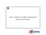
Physical Description
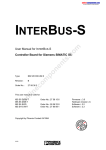
Figure 11 is a front top view of the 3K Base Module. It is made up of two
distinct parts: the dual channel Voice/Fax Module, and the Communications
Control Module (CCM). As viewed from the front, all circuits associated with
voice/fax occupy the left half of the module, while the Communications
Control Module is on the right side. Since this manual deals mainly with
voice/fax functionality, the Communications Control Module will be discussed
only where it directly affects voice/fax operations.
Voice Portion
Communications Control Module Portion
Indicators
Figure 1-1. 3K Base Module, Front Top View
On the right front of the module are the 14 indicators. Of these, the left eight
are associated with the two voice/fax channels, while the last six are related
to the Communications Control Module. The voice/fax indicators will be
discussed in more detail in Sections 5 and 6.
1-1
Marathon 3K Voice/Fax Facility Manual
General Description
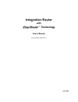
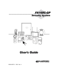
Figure 12 is the rear view of the 3K Base Module. Each voice/fax channel
has a pair of connectors associated with it: RJ1CX and RJ11. These are used
to connect the voice/fax ports to the telephone interface.
RJ-1CX
Marathon 3K
RJ-1CX Connector, E&M interface
RJ11 Connector, FXS/FXO interfaces
Voice/Fax Voice/Fax
Port 1
Port 2
RJ11
Figure 1-2. 3K Base Module, Rear View
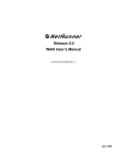
Voice/Fax Operation
Each voice/fax channel converts analog voice obtained from a telephone
interface into digital form, and internally connects the converted voice to the
Communications Control Module portion of the 3K Base Module (see Figure
13). Next, the converted digitized signal is multiplexed with other data to
form part of the Communications Control Module composite data stream.
This data stream is transmitted over a data link to a remote Communications
Control Module.
Voice
3K Base Module
Voice/Fax
Channel
CCM
3K Base Module
CCM
Voice
Voice/Fax
Channel
CCM = Communications Control Module
Figure 1-3. Voice/Fax Operation
At the remote Communications Control Module the digitized voice signal is
demultiplexed, and routed to a compatible voice/fax channel specified by the
destination address. Ultimately, the digitized voice signal is reconverted to
the original analog form.
In addition to accepting analog voice signals for digital conversion, the
voice/fax channel can also process analog signals obtained from a fax machine
or modem. This feature is implemented by resident firmware.
The firmware constantly monitors the incoming analog stream for the
presence of fax or modem signals. When fax or modem signals are detected,
and provided there is currently no voice traffic on the channel, the firmware
switches into the fax/modem mode. While in this mode, the signals are
demodulated into the appropriate fax or modem symbols and passed as data
to the remote end. At the remote end the fax or modem symbols are remodu
lated to the correct standards.
1-2
Marathon 3K Voice/Fax Facility Manual
General Description
Telephone Interface Types
Depending on the telephone interface, the voice/fax facility can be strapped to
conform with one of three common types of signaling convention:
D
E&M (Ear and Mouth) - A tie line trunk circuit used to connect be
tween Private Branch Exchanges (PBXs) or other voice switching sys
tem.
D
FXO (Foreign Exchange Office) - A trunk loop start operation that
emulates a singleline telephone to Central Office lines or CENTREXR
or PBX stations. It recognizes ringing signals and draws current to
indicate an active state.
D
FXS (Foreign Exchange Station) - A station loop start operation that
provides connection to a standard, singleline telephone instrument,
the line circuit of a Key Telephone System (KTS), or a loop start trunk
circuit of a PBX that normally connects to incoming Central Office
(CO) circuits. This interface type provides power and ringing signals
to its interfacing equipment. It is not intended for connection to the
Public Switched Telephone Network (PSTN).
Strapping
All information relating to the strapping of the voice/fax facility interface
types is provided in the 8001846 3Slot Chassis Installation and Cabling
Manual.
Connecting the Voice/Fax Channel to the Telephone Equipment
All information relating to the telephone connection, including interface
cabling and pinouts, is provided in the 8001846 3Slot Chassis Installation
and Cabling Manual.
Compatibility
The 3K voice is compatible with other BLACK BOX analog voice modules. The
voice module with the least features will determine the feature set for the
channel.
Related Documentation
D
Marathon 3Slot Chassis Installation and Cabling Manual, BLACK BOX
D
Marathon Startup Guide,
D
Universal Voice/Fax Module and Telephone Interface Modules User's
Manual
1-3
Configuration
2
Contents
Menu Structure . . . . . . . . . . . . . . . . . . . . . . . . . . . . . . . . . . . . . . . . . . . . . . . . . . . . . . . . . . . . . . . . .
Summary of Options . . . . . . . . . . . . . . . . . . . . . . . . . . . . . . . . . . . . . . . . . . . . . . . . . . . . . . . . .
2-2
2-3
Configuring the Channel Characteristics . . . . . . . . . . . . . . . . . . . . . . . . . . . . . . . . . . . . . . . . . . .
Accessing the Menus . . . . . . . . . . . . . . . . . . . . . . . . . . . . . . . . . . . . . . . . . . . . . . . . . . . . . . . .
Description of Options . . . . . . . . . . . . . . . . . . . . . . . . . . . . . . . . . . . . . . . . . . . . . . . . . . . . . . .
2-6
2-6
2-8
Setting the Voice/Fax Node Parameters . . . . . . . . . . . . . . . . . . . . . . . . . . . . . . . . . . . . . . . . . . .
2-25
Configuring the Voice/Fax Switching Parameters . . . . . . . . . . . . . . . . . . . . . . . . . . . . . . . . . . .
Voice Extension Number . . . . . . . . . . . . . . . . . . . . . . . . . . . . . . . . . . . . . . . . . . . . . . . . . . . . .
Fax Extension Number . . . . . . . . . . . . . . . . . . . . . . . . . . . . . . . . . . . . . . . . . . . . . . . . . . . . . .
Call Inhibit . . . . . . . . . . . . . . . . . . . . . . . . . . . . . . . . . . . . . . . . . . . . . . . . . . . . . . . . . . . . . . . . .
Receive Inhibit . . . . . . . . . . . . . . . . . . . . . . . . . . . . . . . . . . . . . . . . . . . . . . . . . . . . . . . . . . . . . .
Autocall Extension Number . . . . . . . . . . . . . . . . . . . . . . . . . . . . . . . . . . . . . . . . . . . . . . . . . . .
2-26
2-27
2-27
2-27
2-27
2-27
Force Connecting a Voice/Fax Channel . . . . . . . . . . . . . . . . . . . . . . . . . . . . . . . . . . . . . . . . . . . .
Force Connecting Mixed Channels . . . . . . . . . . . . . . . . . . . . . . . . . . . . . . . . . . . . . . . . . . . .
2-29
2-29
Copy Channel Parameters . . . . . . . . . . . . . . . . . . . . . . . . . . . . . . . . . . . . . . . . . . . . . . . . . . . . . . .
2-30
Network Code Download . . . . . . . . . . . . . . . . . . . . . . . . . . . . . . . . . . . . . . . . . . . . . . . . . . . . . . . .
When to Download . . . . . . . . . . . . . . . . . . . . . . . . . . . . . . . . . . . . . . . . . . . . . . . . . . . . . . . . . .
2-31
2-31
This section describes how to configure the voice/fax channel. Your Startup Guide
explains how to access the Command Facility Main Menu.
2-1
Marathon 3K Voice/Fax Facility Manual
Configuration
Menu Structure
Command Facility Main Menu
Configure Local Nodes
Voice/Fax
Option 1
Voice/Fax Channel
Configuration
Option 2
Voice/Fax Node Parameters
Number of Digits
(see page 2-25)
Prompt: ENTER NODE–ID/CHANNEL NUMBER # (^X TO ABORT)
Voice/Fax Channel
Configuration Menu
Voice/Fax Channel
Characteristics
FXS, E&M, FXO
(see page 2-6)
Voice/Fax Switching Parameters
Voice/Fax Extension Number
Call Receive/Inhibit, Autocall
(see page 2-26)
Figure 2-1. Voice/Fax Configuration Outline
2-2
Marathon 3K Voice/Fax Facility Manual
Configuration
Summary of Options
Tables 21 through 23 summarize the configuration options associated with
the voice/fax channel. Refer to pages 27 through 28 for option numbers of
each interface type.
Table 2-1. Voice/Fax Channel Characteristics Options
Option
Telephone
Interface
Default
Description
(Page Reference)
Mode
All
Voice/Fax
Selects two types of channel
signal processing: voice/fax,
and voice only (page 2-8).
Digitizing Rate
All
G.729
Selects one of ten voice
digitizing rates (page 2-9).
Input Level Gain
All
0 dB
Selects one of 26 input signal
gain values in 1-dB increments;
-6 is maximum attenuation; 0 =
no gain; 19 = maximum gain
(page 2-10).
Output Level
Attenuation
All
0 dB
Selects one of 26 output level
attenuation values in 1-dB
increments; 0 = no attenuation;
25 = maximum attenuation
(page 2-10).
Busyout Mode
All
System Controlled
Selects one of three methods of
busyout control (page 2-11).
Bandwidth
All
Voice Activated
Selects how the channel uses
link bandwidth: all the time, only
when voice or fax signals are
present, or dynamically (page
2-12).
Background
All
Regenerated
Selects to either regenerate or
suppress background noise
during idle periods. (page 2-13).
Priority
All
High
Selects either high or low
composite bandwidth priority for
the channel (page 2-13).
Signalling Format
E&M only
DC
Selects one of three types of
signaling format: DC, where
signaling is accomplished by the
state of the E and M leads;
2280, Tone, where signaling is
accomplished by tone over the
analog transmission path; and
pulsed DC, where signaling
follows Ron/Tron convention
(page 2-14).
Signalling Format
FXS only
Interrupted Ring
2/4
Selects one of two ringing
patterns (page 2-14).
2-3
Marathon 3K Voice/Fax Facility Manual
Configuration
Table 2-1. Voice/Fax Channel Characteristics Options (continued)
Option
Telephone
Interface
Default
Description
(Page Reference)
Number of Rings
FXO only
1
Selects number of ring backs
before receipt of dial tone (page
2-15).
Analog Operation
E&M only
4-wire
Sets channel for either 2-wire or
4-wire operation (page 2-16).
Ringing
Frequency
FXS only
25 Hz
Selects 25 Hz or 50 Hz ringing
frequency (page 2-16).
Fax Digitizing
Rate
All
Voice Rate
Selects 1 of 5 digitizing rates for
fax operation (page 2-17).
Disconnect
Supervision
FXO only
Tone
Selects either tone or power
interrupt disconnect supervision
(page 2-18).
Line Impedance
FXS, FXO,
and E&M
2-wire only
600 ohms
Selects one of two line
impedance matching types
(page 2-19).
Maximum Output
Level
E&M 4-wire
only
0 dBm
Selects one of two maximum
output levels (page 2-20).
Regeneration
Delay
All
1
Delays from 1 to 15 seconds the
forwarding of dial digits to the
destination PBX (page 2-20).
Dial Digit Time
Limit
All
10
Selects from 1 to 15 seconds of
interdigit time limit. When time
limit is reached, the voice/fax
channel stops detecting dialing
digits (page 2-21).
Maximum Number
of Forwarded
Digits
All
0
Ranges from 1 to 16. When the
configured number is reached,
the digits are forwarded without
waiting for the time limit (page
2-22).
0 disables the single dial tone
feature.
2-4
Regeneration
Format
All
Dial Pulse
Specifies 1 of 2 types of
regeneration format, pulse or
DTMF (page 2-23).
Call Progress
Tone
All
North American
Specifies 1 of of 8 types of call
progress tones, as required in
selected countries or regions
(page 2-23).
Marathon 3K Voice/Fax Facility Manual
Configuration
Table 2-2. Voice/Fax Node Parameters Option
Option
Number of
Digits
No.
1
Telephone
Interface
FXS
E&M
FXO
Default
2
Description
Specifies number of digits (1-4) to be
assigned to each voice/fax extension
(page 2-25).
Table 2-3. Voice/Fax Switching Parameters Options
Option
No.
Telephone
Interface
Default
Description
Assigns the telephone extension number
to the voice/fax channel (page 2-27).
Voice
Extension
Number
1
FXS
E&M
FXO
–
Fax
Extension
Number
2
Not used in
the Marathon
3K
–
Call Inhibit
3
FXS
E&M
FXO
NO
When set to YES, prevents the voice/fax
channel from calling another voice/fax
channel (page 2-27). It can only answer
calls.
Receive
Inhibit
4
FXS
E&M
FXO
NO
When set to YES, prevents the voice/fax
channel from receiving calls (page 2-27).
It can only originate calls.
Autocall
Extension
Number
5
FXS
E&M
FXO
–
When off-hook, automatically calls the
configured extension number (page
2-27).
2-5
Marathon 3K Voice/Fax Facility Manual
Configuration
Configuring the Channel Characteristics
Accessing the Menus
To access the channel characteristics menus, access the Command Facility
Main Menu, then follow this path.
Command Facility Main Menu
Configure Local Nodes
Voice/Fax
Prompt: ENTER NODE–ID/CHANNEL # (^X TO ABORT):
Typical Entry:
SIMI/E1
where Simi is the node ID,
and E1 is voice/fax channel 1
<cr>
VOICE/FAX CHANNEL CONFIGURATION
Voice/Fax Channel
Characteristics
FXS Interface
Voice/Fax Channel
Characteristics Menu
FXO Interface
Voice/Fax Channel
Characteristics Menu
E&M Interface
Voice/Fax Channel
Characteristics Menu
see page 2-7
see page 2-8
see page 2-7
The menu you will see depends on the type of interface you have.
2-6
Marathon 3K Voice/Fax Facility Manual
Configuration
FXS Interface
VOICE/FAX CHANNEL CHARACTERISTICS [node ID/channel #]
1. MODE
[VOICE/FAX]
2. DIGITIZING RATE
[G.729]
3. INPUT LEVEL GAIN
[0 dB]
4. OUTPUT LEVEL ATTENUATION
[0 dB]
5. BUSYOUT MODE
[SYSTEM CONTROLLED]
6. BANDWIDTH
[VOICE ACTIVATED]
7. BACKGROUND
[REGENERATED]
8. PRIORITY
[HIGH]
9. SIGNALLING FORMAT
[INTERRUPTED RING]
10. RINGING FREQUENCY
[25 HZ]
11. FAX DIGITIZING RATE
[VOICE RATE]
12. LINE IMPEDANCE
[600 OHMS]
13. REGENERATION DELAY
[1]
14. DIAL DIGIT TIME LIMIT
[10]
15. MAXIMUM NUMBER OF FORWARDED DIGITS
[0]
[DIAL PULSE]
16. REGENERATION FORMAT
17. CALL PROGRESS TONE
[N. AMER]
CR - ACCEPT ENTRY
M - MAIN MENU
Note:
The information in brackets shown in the menus are the default values. As you
configure your unit, the information displayed will be updated to the current values.
E&M Interface
VOICE/FAX CHANNEL CHARACTERISTICS [node ID/channel #]
1. MODE
[VOICE/FAX]
2. VOICE DIGITIZING RATE
[G.729]
3. INPUT LEVEL GAIN
[0 dB]
4. OUTPUT LEVEL ATTENUATION
[0 dB]
5. BUSYOUT MODE
[SYSTEM CONTROLLED]
6. BANDWIDTH
[VOICE ACTIVATED]
7. BACKGROUND
[REGENERATED]
8. PRIORITY
[HIGH]
9. SIGNALLING FORMAT
[DC]
10. ANALOG OPERATION
[4-WIRE]
11. FAX DIGITIZING RATE
[VOICE RATE]
12. LINE IMPEDANCE (2WIRE ONLY)
[600 OHMS]
13. MAXIMUM OUTPUT LEVEL (4-WIRE ONLY)
[0 DBM]
14. REGENERATION DELAY
[1]
15. DIAL DIGIT TIME LIMIT
[10]
16. MAXIMUM NUMBER OF FORWARDED DIGITS
[0]
17. REGENERATION FORMAT
[DIAL PULSE]
18. CALL PROGRESS TONE
[N. AMER]
CR - ACCEPT ENTRY
M - MAIN MENU
Note:
The information in brackets is the default value. As you configure your unit, the
information displayed will be updated to the current values.
2-7
Marathon 3K Voice/Fax Facility Manual
Configuration
FXO Interface
VOICE/FAX CHANNEL CHARACTERISTICS [node ID/channel #]
1. MODE
[VOICE/FAX]
2. DIGITIZING RATE
[G.729]
3. INPUT LEVEL GAIN
[0 dB]
4. OUTPUT LEVEL ATTENUATION
[0 dB]
5. BUSYOUT MODE
[SYSTEM CONTROLLED]
6. BANDWIDTH
[VOICE ACTIVATED]
7. BACKGROUND
[REGENERATED]
8. PRIORITY
[HIGH]
9. NUMBER OF RINGS
[1]
10. FAX DIGITIZING RATE
[VOICE RATE]
11. DISCONNECT SUPERVISION
[TONE]
12. LINE IMPEDANCE
[600 OHMS]
13. REGENERATION DELAY
[1]
14. DIAL DIGIT TIME LIMIT
[10]
15. MAXIMUM NUMBER OF FORWARDED DIGITS
[0]
16. REGENERATION FORMAT
[DIAL PULSE]
17. CALL PROGRESS TONE
[N. AMER]
CR - ACCEPT ENTRY
M - MAIN MENU
Note:
The information in brackets is the default value. As you configure your unit, the
information displayed will be updated to the current values.
Description of Options
Mode
The MODE option of the Channel Characteristics Menu allows you to select
two types of voice/fax operation.
MODE [VOICE/FAX]
1. VOICE/FAX
2. VOICE ONLY
CR - ACCEPT ENTRY
M - MAIN MENU
N - NEXT ENTRY
ENTRY:
If you select the VOICE/FAX option, the channel will process voice or fax
signals, as follows: Normally the channel operates in the voice mode. If a fax
signal is detected, and provided there is no voice traffic over that channel, the
channel will automatically switch to the fax mode. It will stay in that mode
until fax signals are no longer detected, and then switch back to the voice
mode. Use this option for most voice/fax applications.
2-8
Marathon 3K Voice/Fax Facility Manual
Configuration
If you select the VOICE ONLY option, the voice/fax channel will be in the
voice mode all the time. Use this as the preferred option if the channel is to
be dedicated to voice traffic.
Note:
When force connected, both local and remote channels must be configured for
the same mode. When attempting a switched call, if either channel is set to
Voice Only, that call will operate in the Voice Only mode.
Digitizing Rate
The DIGITIZING RATE option of the Channel Characteristics Menu allows
you to select one of 10 voice digitizing rates in bps as shown in the following
display. Higher voice digitizing rates will usually produce crisper voice
communications. However, higher digitizing rates may result in overbooking
of composite bandwidth.
DIGITIZING RATE
1. 4000
2. 4800
3. 6400
4. 7200
5. 8000
6. 9600
7. 12000
8. 14400
9. 16000
10. G.729
[G.729]
CR - ACCEPT ENTRY
M - MAIN MENU
N - NEXT MENU
ENTRY:
The G.729 option, part of the ClearVoice Technology, is incorporated in
Release 5.0 or later Marathon 3K units. It uses a voice compression algo
rithm based on International Telecommunications Union's (ITU) G.729
recommendations. With G.729, voice is digitized at 8 Kbps, but produces
voice quality equivalent to 32Kbps voice using Adaptive Differential Pulse
Code Modulation (ADPCM).
If you call a network extension that does not have the G.729 option, the call
will reduce to the lowest rate and utilize the older voice algorithm. See Table
24 for compatibility details.
When in the force connect mode, you may use the G.729 option only when
both sides are set to G.729.
Bandwidth Selection
With the voice rate of a voice channel configured for G.729 rate, use VOICE
ACTIVATED only. If you select DYNAMIC or CONTINUOUS, the message
NOT SUPPORTED" will appear.
2-9
Marathon 3K Voice/Fax Facility Manual
Configuration
Table 2-4. Compatibility Matrix
Node A
Voice/Fax Channel
Node B
Rel. Level
Voice/Fax Channel
Rel. Level
Compatibility
Configured for G.729
rate
5.0
Configured for G.729 rate
5.0
Fully compatible,
operating with G.729
algorithm.
Configured for G.729
rate
5.0
G.729 or non-G.729,
configured for 4 Kbps to
7.2 Kbps
5.0
Operates with older
voice algorithm at a
lower rate.1
Configured for G.729
rate
5.0
G.729 or non-G.729,
configured for 8 Kbps to
16 Kbps
5.0
Operates with older
voice algorithm at
8 Kbps.1
Configured for G.729
rate
5.0
G.729 or non-G729 rate
4.3 or earlier
Operates with older
voice algorithm at the
lowest rate.1
1 Will not operate in force connect mode
Input and Output Levels
The INPUT LEVEL option of the Channel Characteristics Menu provides one
of 26 choices of input signal amplification settings in 1 dB increments as
shown in the following display; -6 dB is maximum attenuation (negative
gain), 0 is no amplification, and 19 dB is maximum amplification. The
default is 0 dB.
Note:
If your equipment is operated in the U.S.A. or Canada, input and output levels
must be set to 0 dB. See Appendix B for details.
INPUT LEVEL GAIN
1.
-6 dB
2.
-5 dB
3.
-4 dB
4.
-3 dB
5.
-2 dB
6.
-1 dB
7.
0 dB
8.
1 dB
9.
2 dB
10.
3 dB
11.
4 dB
12.
5 dB
13.
6 dB
CR
M
N
-
ENTRY:
2-10
[0 dB]
14.
15.
16.
17.
18.
19.
20.
21.
22.
23.
24.
25.
26.
ACCEPT ENTRY
MAIN MENU
NEXT MENU
7 dB
8 dB
9 dB
10 dB
11 dB
12 dB
13 dB
14 dB
15 dB
16 dB
17 dB
18 dB
19 dB
Marathon 3K Voice/Fax Facility Manual
Configuration
The OUTPUT LEVEL option of the Channel Characteristics Menu provides
one of 26 choices of output signal attenuation settings in 1 dB increments as
shown in the following display; 0 dB is no attenuation and 25 dB is maximum
attenuation.
OUTPUT LEVEL ATTENUATION [0dB]
1.
0 dB
14. 13 dB
2.
1 dB
15. 14 dB
3.
2 dB
16. 15 dB
4.
3 dB
17. 16 dB
5.
4 dB
18. 17 dB
6.
5 dB
19. 18 dB
7.
6 dB
20. 19 dB
8.
7 dB
21. 20 dB
9.
8 dB
22. 21 dB
10.
9 dB
23. 22 dB
11.
10 dB
24. 23 dB
12.
11 dB
25. 24 dB
13.
12 dB
26. 25 dB
CR
M
N
-
ACCEPT ENTRY
MAIN MENU
NEXT MENU
ENTRY:
Busyout Mode
The BUSYOUT MODE option of the Channel Characteristics Menu allows
you to select one of three busyout modes.
BUSYOUT MODE [SYSTEM CONTROLLED]
1. SYSTEM CONTROLLED
2. FORCED ON
3. FORCED OFF
CR - ACCEPT ENTRY
M - MAIN MENU
N - NEXT ENTRY
ENTRY:
Selecting SYSTEM CONTROLLED will cause the system to place the
channel in the busyout state in a force connect mode when there is no link
bandwidth available for the voice/fax channel.
Selecting FORCED ON forces the voice/fax channel into the busyout state.
This option is used to disable an intermittent or defective voice/fax channel
until it can be repaired.
2-11
Marathon 3K Voice/Fax Facility Manual
Configuration
Selecting FORCED OFF prevents a forceconnected channel from going busy,
overriding any other existing conditions. Normally, this option is used when
the channel is being tested.
Note that, when the channel is in the busyout mode, the LO indicator will
flash every second.
Bandwidth
The BANDWIDTH option of the Channel Characteristics Menu allows you to
select one of three methods of bandwidth utilization by the voice/fax channel.
BANDWIDTH [VOICE ACTIVATED]
1. VOICE ACTIVATED
2. CONTINUOUS
3. DYNAMIC
CR - ACCEPT ENTRY
M - MAIN MENU
N - NEXT ENTRY
ENTRY:
Note:
D
In a force connect mode, bandwidth must be set the same way at both
ends. If changed at one end the connection will be disrupted until the other
end is changed to match.
D
When using the G.729 option, select VOICE ACTIVATED. Do not select
the other options.
When VOICE ACTIVATED is selected, the channel uses link bandwidth only
when speech or fax signals are present.
When CONTINUOUS is selected, link bandwidth is dedicated to the channel
while that channel is active (offhook), even during pauses in voice and fax
signal transmissions; while active, the bandwidth of this channel is not
available for other voice/fax, data, or LAN traffic. You may use this option if
it is desired to transmit background noise, subject to availability of link
bandwidth. If you use this option in pulsed dc E&M applications, then you
will be using bandwidth even when the voice/fax channel is idle (similar to a
TDM operation).
When DYNAMIC is selected, the voice/fax channel will normally operate at
the configured digitizing rate, but will reduce to a lower rate when demand
on composite link is heavy. This feature is effective over multiple hops, and is
limited to internodal delays of 60 milliseconds or less. As a general rule, use
option 3 in networks of less than four nodes (threenode hops). If these
limitations are exceeded, the dynamic voice option may cause voice dropouts
during network congestion. This option is not recommended for operation
over satellite links and for tandem circuits, and is not supported in BLACK BOX
mux channels. Channels operating in the fax mode will not be down rated.
2-12
Marathon 3K Voice/Fax Facility Manual
Configuration
Background
The BACKGROUND option of the Channel Characteristics Menu provides
you with two options for managing background noise.
BACKGROUND [REGENERATED]
1. REGENERATED
2. SILENCE
CR - ACCEPT ENTRY
M - MAIN MENU
N - NEXT ENTRY
ENTRY:
When REGENERATED is selected, background sound is reproduced locally
and heard by the local telephone user.
When SILENCE is selected, gaps in speech are filled by silence. Try both
options, then choose the preferred setting.
Priority
This option allows you to set a high or low bandwidth priority level for the
selected voice/fax channel. This feature is primarily intended to establish
priority between synchronous data channels and voice/fax channels during
heavy demands on composite bandwidth. The default setting for every
voice/fax channel is HIGH, and for every synchronous data channel is LOW.
PRIORITY [HIGH]
1. HIGH
2. LOW
CR - ACCEPT ENTRY
M - MAIN MENU
N - NEXT ENTRY
ENTRY:
Selecting one or more synchronous channels for high priority will allow those
channels to contend equally with voice/fax channels for link bandwidth.
If the link bandwidth for the voice/fax channels is overbooked, then Dynamic
Bandwidth is recommended. See page 212.
If you set the voice/fax channels for LOW priority and the synchronous
channels for HIGH priority, then voice performance will clearly suffer, and
Bandwidth should be configured to DYNAMIC to prevent voice breakup.
However, voice breakup may still occur if the synchronous channels and
minimum voice rates exceed the link bandwidth.
2-13
Marathon 3K Voice/Fax Facility Manual
Configuration
Signalling Format
FXS
FXS SIGNALLING FORMAT [INTERRUPTED RING]
1. REPEATED RING
2. INTERRUPTED RING
CR - ACCEPT ENTRY
M - MAIN MENU
N - NEXT ENTRY
ENTRY:
When REPEATED RING is selected, ringing depends on the ring cycle
generated by the PBX. REPEATED RING must be used when the local
channel is force connected to the remote channel, and the remote channel is
strapped for FXO.
When INTERRUPTED RING is selected, it causes the local telephone to ring
when the remote telephone is lifted offhook, or vice versa. The ringing
cadence is as follows:
ring for two seconds, off for four seconds.
INTERRUPTED RING is normally selected when an FXSstrapped voice/fax
channel is connected to another FXS or E&Mstrapped voice/fax. INTER
RUPTED RING must be selected for switched voice calls channels.
Note:
INTERRUPTED RING selects the ringing cadence of the telephone set attached to the FXS-strapped voice/fax channel. It does not affect the cadence of
the ring back heard by the user originating the call. That cadence is selected
from the Call Progress Tones Menu as detailed on page 2-24.
E&M
E&M SIGNALLING [DC]
1. DC
2. 2280 TONE
3. PULSED DC
CR - ACCEPT ENTRY
M - MAIN MENU
N - NEXT ENTRY
ENTRY:
When DC is selected, the channel senses the idle/active status by the DC
condition of the Mlead, and sends the idle/active status to the remote
channel as a DC condition of the Elead.
2-14
Marathon 3K Voice/Fax Facility Manual
Configuration
When 2280 TONE, is selected, the channel senses the idle status by the
presence of a 2280Hz tone on the TR pair, and holds a 2280Hz tone as an
idle condition on the T1R1 pair. Option 2 supports CEPTL1 circuits such as
the AC15 circuits in the United Kingdom. Both ends of the circuit must
support this signaling format and the channel must be force connected. This
option can only be selected when the channel is configured for 4wire analog
operation (refer to page 216).
When PULSED DC is selected, going offhook is indicated by a pulse of
medium duration, and going onhook is indicated by a pulse of a longer
duration. Pulsed DC includes the Ron/Tron signaling convention. Both ends
of the circuit must support this signaling format, and the channel must be
force connected. In this mode, signals on the M lead are reproduced on the
distant E lead and the voice/fax channel is not affected by the state of the
signaling levels.
Number of Rings
NUMBER OF RINGS [1]
1.
1
2.
2
3.
3
4.
4
5.
5
6.
6
7.
7
8.
8
9.
9
CR - ACCEPT ENTRY
M - MAIN MENU
N - NEXT MENU
ENTRY:
Application: In voice/fax switching, with the local channel fitted with an FXO
interface module.
PBX
Trunk
Side
Local Marathon 3K
Remote Marathon 3K
Station
Side
Strapped
for FXO
Strapped
for FXS
2-15
Marathon 3K Voice/Fax Facility Manual
Configuration
When an attempt is made to contact a network channel from a PBX station,
the user first dials the local FXO station number and waits for a second dial
tone. In response, the local FXO channel waits one or more ring cycles before
providing that dial tone. Then the user dials the extension number of the
network channel. It is the number of ring cycles before the dial tone that is
selected with this option.
Notes:
D
The NUMBER OF RINGS option applies only to calls originating at the FXO
side of the WAN; it does not affect calls received by the FXO side.
D
If the number of rings is configured for 8 or 9, the actual number of rings
heard may be 9 or more.
Analog Operation
E&M
ANALOG OPERATION [4WIRE]
1. 2WIRE
2. 4WIRE
CR - ACCEPT ENTRY
M - MAIN MENU
N - NEXT ENTRY
ENTRY:
Select the setting, as appropriate, to match the voice/fax channel with the
associated PBX equipment.
Note:
You must select the 4-WIRE option if you have selected the 2280 TONE signalling option on page 2-14.
Ringing Frequency
FXS
RINGING FREQUENCY [25 HZ]
1. 25 HZ
2. 50 HZ
CR - ACCEPT ENTRY
M - MAIN MENU
N - NEXT ENTRY
ENTRY:
This option controls the signal that rings the bell on the telephone to indicate
that a call is coming to that location.
The 25 HZ option is normally used. However, some European telephone
systems will only operate with a 50Hz ringing frequency.
2-16
Marathon 3K Voice/Fax Facility Manual
Configuration
Fax Digitizing Rate
This option allows you to select one of five fax digitizing rates.
FAX DIGITIZING RATE (bps) [VOICE RATE]
1. VOICE RATE
2. 2400
3. 4800
4. 7200
5. 9600
CR - ACCEPT ENTRY
M - MAIN MENU
N - NEXT ENTRY
ENTRY:
The VOICE RATE option sets the fax digitizing to the same rate configured
for voice (see page 29). The other four options (2 through 5) are used when
voice and fax require different digitizing rates, typically when the voice rate
is below 9600 bps. If you select VOICE RATE, and the voice digitizing rate is
set for G.729 (see page 29), the fax signals will be digitized at 7.2 Kbps.
Manual fax switchover is not supported. You cannot send a fax message
while a voice call is in progress; you must first set the fax machine or modem
to auto answer and place a new call. The fax/modem detector relies on the
answer tone of the called device. This tone is provided automatically when
the called device is set for the auto answer mode.
2-17
Marathon 3K Voice/Fax Facility Manual
Configuration
Disconnect Supervision
Disconnect supervision is the means used to disconnect a switched telephone
connection when the telephone equipment at one end goes from an offhook
(active) to an onhook (idle) state.
Disconnect supervision is not effective in a forced telephone connection.
However, Autocall can be used to accomplish a similar operation and provide
disconnect supervision between an FXO and an FXS interface pair.
Voice/fax channels strapped for FXO can detect one of two types of disconnect
supervision signals: power interrupt, or tone. In case of power interrupt, the
voice/fax channel monitors the station line of the attached PBX or CO for the
absence of loop current for 600 ms or longer.
PBX
Marathon 3K
Trunk
Side
Station
Side
Power Interrupt Pulse
FXO
If the attached PBX or CO cannot supply a power interrupt signal, the
voice/fax channel looks for a call progress tone of 600 Hz or less.
DISCONNECT SUPERVISION [TONE]
1. TONE
2. POWER INTERRUPT
CR - ACCEPT ENTRY
M - MAIN MENU
N - NEXT ENTRY
ENTRY:
Select TONE if the attached PBX or Central Office (CO) cannot supply a
power interrupt pulse. Select POWER INTERRUPT if the attached PBX or
CO provides a 600ms power interrupt pulse when the telephone set on the
other side goes onhook. This setting is recommended for CENTREX (Bell
System) or CENTRANET (GTE) station lines from the CO.
2-18
Marathon 3K Voice/Fax Facility Manual
Configuration
Line Impedance (FXS, FXO, and E&M 2-Wire Only)
LINE IMPEDANCE [600 OHMS]
1. 600 OHMS
2. COMPLEX
CR - ACCEPT ENTRY
M - MAIN MENU
N - NEXT ENTRY
ENTRY:
The LINE IMPEDANCE option provides impedance matching choices for the
FXS, FXO, and E&M 2wire interfaces as shown in Table 25. The line
impedance of E&M interface configured for 4wire operation is fixed at 600
ohms and is not configurable.
Table 2-5. Line Impedance Matching Options
For Different Interface Modules
Option
1. 600 W
2. Complex
FXS
FXO
E&M
2-wire
E&M
4-wire
600 W
resistive
No
No
Yes
Fixed
600 W
+ 2.2 mF
Yes
Yes
No
No
370 W
+ 0.31 mF //
620 W
or
220 W
+ 0.12 mF //
820 W
Yes
Yes
Yes
No
Impedance
The symbol // means in parallel with.
2-19
Marathon 3K Voice/Fax Facility Manual
Configuration
Maximum Output Level (E&M 4-Wire Only)
The +7 dBm option of this menu is used when the interfacing tie trunk
equipment includes a pad. Use 0 dBm NOMINAL for all other applications.
MAXIMUM OUTPUT LEVEL [0 dBm NOMINAL]
1. 0 dBm NOMINAL
2. +7 dBm
CR - ACCEPT ENTRY
M - MAIN MENU
N - NEXT ENTRY
ENTRY:
This menu, in combination with the output level attenuation setting on page
211, determines the final value of the output level. For example, if +7 dB is
selected here, and the output level attenuation on page 211 is set to 5 dB,
the resultant output level is a net gain of + 2 dB.
Regeneration Delay
This menu is part of the Single Dial Tone function described on page 313.
Ranging from 1 to 15 seconds, the selected delay compensates for the time it
takes for the remote PBX to go offhook and and be ready to accept dialing
from the voice/fax channel for completing the call setup. Default is 1 second.
REGENERATION DELAY [1]
1. 1
9.
9
2. 2
10. 10
3. 3
11. 11
4. 4
12. 12
13. 13
5. 5
6. 6
14. 14
15. 15
7. 7
8. 8
CR - ACCEPT ENTRY
M - MAIN MENU
N - NEXT MENU
2-20
Marathon 3K Voice/Fax Facility Manual
Configuration
Dial Digit Time Limit
This option is part of the Single Dial Tone function described on page 313.
DIAL DIGIT TIME LIMIT [10]
1. 1
9.
9
2. 2
10. 10
3. 3
11. 11
4. 4
12. 12
13. 13
5. 5
6. 6
14. 14
15. 15
7. 7
8 8
CR - ACCEPT ENTRY
M - MAIN MENU
N - NEXT MENU
Ranging from 1 to 15 seconds, this option specifies the maximum time (from
the start of one digit to the start of the next) for accepting dialed digits.
When the time limit is reached, the accumulated digits are compared to the
node's configured Number of Digits as defined on page 225. If the accumu
lated number is less than the configured Integration network number, a
reorder (fast busy) response signal is generated. If the accumulated number
is equal to or more than the configured number, a call request is generated.
The default is 10 seconds. This allows a person time to pause and check a
number being dialed. When using pulse dialing, this parameter must be set
for 2 seconds or more to accommodate the highorder digits, such as 9 or 0
which take a longer time to record.
2-21
Marathon 3K Voice/Fax Facility Manual
Configuration
Maximum Number of Forwarded Digits
MAXIMUM NUMBER OF FORWARDED DIGITS [16]
1.
0
10. 9
2.
1
11. 10
3.
2
12. 11
4.
3
13. 12
5.
4
14. 13
6.
5
15. 14
7..
6
16. 15
8.
7
17. 16
9.
8
CT - ACCEPT ENTRY
M - MAIN MENU
N - NEXT MENU
This menu is part of the Single Dial Tone feature described on page 313.
Ranging from 1 to 16, the selected value specifies the maximum number of
dialing digits to be forwarded to any destination voice channel in the net
work. If this number is reached, the call proceeds without having to wait
until the Dial Digit Time Limit is reached.
The default value is 0, which will disable the Single Dial Tone feature. This
assures backward compatibility, and requires positive action by the user to
enable this feature.
When used in conjunction with a line configured to pulse dialing, this feature
may be used to set limits on call routing. For example:
2-22
D
A value of 4 or 5 will restrict calls to within a private network.
D
A value of 8 will restrict calls to local calls from the PBX.
D
A value of 9 will restrict calls to within the area code from the PBX.
D
A value of 11 will restrict calls to within the country.
D
Values beyond 11 would allow placing of international calls with resul
tant administrative call accounting issues.
Marathon 3K Voice/Fax Facility Manual
Configuration
Regeneration Format
REGENERATION FORMAT [DIAL PULSE]
1. DIAL PULSE
2. DTMF
CR - ACCEPT ENTRY
M - MAIN MENU
N - NEXT MENU
This option is in support of the Single Dial Tone feature described on
page 313. Designed for E&M and FXO interfaces, it allows the voice/fax
channel to match the outgoing dialing digits with that of the interfacing PBX.
Default is Dial Pulse. The voice/fax channel can accept either Dial Pulse or
DTMF input digits.
Select DIAL PULSE for FXO and E&M interfaces if the interfacing PBX
requires a dial pulse format. On FXS and FAX interfaces, selecting DIAL
PULSE will result in no digits forwarded.
Select DTMF for FXO and E&M interfaces if the interfacing PBX requires a
DTMF format. Select DTMF for FXS or FAX interfaces when used with PBXs
or Key Systems equipped with DISA (Direct Inward System Access).
Call Progress Tones
CALL PROGRESS TONES [N.AMER]
1. N. AMER
2. JAPAN
3. U.K.
4. EUROPE
5. FRANCE
6. C. AMERICA
7. CHILE
8. AUSTRALIA
CR - ACCEPT ENTRY
M - MAIN MENU
N - NEXT MENU
This menu allows you to match the call progress tones to one of eight
countries or areas where the Integration network is installed. Details are
listed in Table 26.
2-23
Marathon 3K Voice/Fax Facility Manual
Configuration
Table 2-6. Definition of Call Progress Tones
Dial
Cadence
Frequency
Ringing
Cadence
Frequency
Busy
Cadence
Frequency
1
Continuous
350 + 440
2–4
440 + 480
0.5 – 0.5
480 + 620
0.25 – 0.25
480 + 620
North America
2
Continuous
440
1–2
384 + 416
0.5 – 0.5
400
0.5 – 0.5
400
Japan
3
Continuous
350 + 440
0.4 – 0.2 –
0.4 – 2
440 + 450
0.375 –
0.375 400
0.4 – 0.35 – 0.225
– 0.525
400
United Kingdom
4
Continuous
425
1–4
425
0.5 – 0.5
425
0.25 – 0.25
425
Europe
5
Continuous
425 + 455
1.6 – 3.33
400
0.25 – 0.25
440
0.25 – 0.25
440
France
6
Continuous
425
1–4
425
0.25 – 0.25
425
0.25 – 0.25
425
Brazil, Mexico
7
Continuous
400
1–3
400
0.5 – 0.5
400
0.5 – 0.5
400
Chile
8
Continuous
400+425
0.4 – 0.2 –
0.4 – 2
400 + 450
0.375 –
0.375 425
0.375 – 0.375
425
Australia
Option
Congestion
Cadence
Frequency
0.4 – 0.2 –
0.4 – 2
400 + 450
Example: In Australia, tones of 400 and 450 Hz are:
D
D
D
D
2-24
on for 400 milliseconds
silent for 200 milliseconds
on for 400 milliseconds
silent for 2 seconds
Country
Marathon 3K Voice/Fax Facility Manual
Configuration
Setting the Voice/Fax Node Parameters
To configure the voice/fax channel node parameters, access the Command
Facility Main Menu and follow this path:
Command Facility Main Menu
Configure Local Nodes
Voice/Fax
Voice/Fax Channel
Node Parameters
VOICE/FAX NODE PARAMETERS
1. NUMBER OF DIGITS
CR - ACCEPT ENTRY
M - MAIN MENU
P - PREVIOUS MENU
ENTRY:
NUMBER OF DIGITS [2]
1. 1
2. 2
3. 3
4. 4
CR - ACCEPT ENTRY
M - MAIN MENU
N - NEXT ENTRY
ENTRY:
Ranging from 1 through 4, the value selected specifies the number of digits
that need to be configured for all voice/fax extension numbers (channels)
within the local node. Once configured, a voice/fax channel within any node
can call only another voice/fax channel that has the same number of digits.
2-25
Marathon 3K Voice/Fax Facility Manual
Configuration
Configuring the Voice/Fax Switching Parameters
To configure the channel voice/fax switching parameters, access the Com
mand Facility Main Menu and follow this path:
Command Facility Main Menu
Configure Local Nodes
Voice/Fax
Prompt: ENTER NODE-ID/CHANNEL # <^X TO ABORT>:
<cr>
Typical Entry:
SIMI/E1
where Simi is the node ID,
and E1 is voice/fax channel 1
VOICE/FAX CHANNEL CONFIGURATION
Voice/Fax Channel
Configuration Menu
VOICE/FAX SWITCHING PARAMETERS
VOICE/FAX SWITCHING PARAMETERS [node ID/channel#]
1. VOICE EXTENSION NUMBER
[XXXX]
2. FAX EXTENSION NUMBER
[XXXX]
3. CALL INHIBIT
[NO]
4. RECEIVE INHIBIT
[NO]
5. AUTOCALL EXTENSION NUMBER
[XXXX]
CR - ACCEPT ENTRY
M - MAIN MENU
P - PREVIOUS MENU
ENTRY:
where xxxx shows the current number
2-26
Marathon 3K Voice/Fax Facility Manual
Configuration
Voice Extension Number
The VOICE EXTENSION NUMBER option of the Voice/Fax Switching
Parameters Menu is used to assign the telephone extension number to the
voice/fax channel. There is no default value. When this option is selected,
the following display will appear on the screen:
ENTER VOICE EXTENSION (^X TO ABORT):
Enter 1 through 4 decimal digits. The number of digits entered must match
the number specified in the voice/fax node parameters option (see page 225).
If the entry does not contain the exact number of required digits, you will
receive an error message.
To erase a prevously configured voice extension number, select VOICE
EXTENSION option, then type in one space (space bar) followed by <cr>.
Fax Extension Number
This option is not supported by the Marathon 3K voice/fax channel.
Call Inhibit
YES, prevents the voice/fax channel from calling another voice/fax channel.
Default is NO.
Receive Inhibit
YES, prevents the voice/fax channel from receiving calls. Default is NO.
Autocall Extension Number
This option allows the local user to preselect a fixed destination (extension
number) within the Integration network. Then, when the local voice/fax
channel goes offhook, it is automatically connected to that extension number.
Although outbound calls are directed to a single destination, the local
voice/fax channel maybe accessed by multiple sources; when onhook, it is
free to receive calls from any of the other extensions within the Integration
network provided that Receive Inhibit is not enabled.
2-27
Marathon 3K Voice/Fax Facility Manual
Configuration
Application
Autocall allows multiple users to contend for a limited number of resources
within the Integration network. As shown in the following example, a
headquarters office in Los Angeles is connected over three separate WAN
links to field offices in Chicago, Simi, and Dallas. Each office is served by a
single voice/fax channel. Specifically, the Los Angeles office is connected over
an FXOstrapped voice/fax channel to PBX station 1234. The three field
offices are strapped for FXS. Each voice/fax channel is assigned a 3digit
Integration network extension number as shown. In addition, the three field
offices are configured with autocall enabled, and with autocall extension
number configured for X345.
Any of the field office users can access the Los Angeles PBX by simply lifting
the telephone offhook and be automatically connected to PBX station 1234.
From there the user can dial any other PBX station or dial an access code for
a PSTN dial tone.
Chicago
Marathon 3K
Los Angeles
Marathon 3K
Voice/Fax
Channel
PBX
1234
FXO
X345
Voice/Fax
Channel
FXS
X234 or
X678 or
X567
Voice/Fax
Channel
FXS
X567 or
X678 or
X567
1235
1236
Dallas
Marathon 3K
PSTN
Voice/Fax
Channel
FXS
X567 or
X678 or
X567
2-28
Simi
Marathon 3K
Marathon 3K Voice/Fax Facility Manual
Configuration
To Configure
To configure an autocall extension number, select AUTOCALL EXTENSION
NUMBER from the Voice/Fax Switching Parameters Menu. The following
display will appear on the screen:
ENTER AUTOCALL EXTENSION (^X TO ABORT):
The destination number selected must match an already configured extension
number within the Integration network.
To erase a prevously configured autocall extension number, select AUTO
CALL EXTENSION NUMBER, then type in one space (space bar) followed
by <cr>.
Force Connecting a Voice/Fax Channel
As described earlier, voice/fax channels can be either switched or dedicated
(force connected). Any channel that is not force connected is a switched
channel. Normally, users connected to a switched voice/fax channel can call
any other compatible voice/fax channel within the network by dialing the
extension number of that channel.
In contrast, a forceconnected voice/fax channel is paired up for connection
with one other voice/fax channel only. It can neither call nor be called by
other than the channel with which it is paired up, even when configured with
an extension number. The procedure for force connecting a voice/fax channel
follows.
Notes:
D
The term “remote node” used in this procedure suggests that the other
(mating) voice/fax channel is located in a remote Integration node, the most
common application. You may, in fact, force connect any two voice/fax
channels, including two within the same node or even within the same 3K
Base Module. This is a convenient way to test voice/fax channels either
before or after the network is in operation.
D
Any voice/fax channel using AC15, Ron Tron, or wink start type signaling
cannot be switched and must be force connected.
D
Delay dial is not supported in force-connected channels
2-29
Marathon 3K Voice/Fax Facility Manual
Configuration
Force Connecting Mixed Channels
Do not force connect a voice/fax channel configured for G.729 with a voice/fax
channel configured for any nonG.729 rate.
From the: Command Facility Main Menu
Switching Control
Force Connect
Prompt: ENTER FROM NODE-CHANNEL # (OR RANGE OF CHANNELS)
(^X TO ABORT):
Typical Entry:
SIMI/E1
Prompt: ENTER TO NODE-ID/CHANNEL # (^X TO ABORT):
Typical Entry:
MPARK/E2
Entering this command will replace an existing connection with the new one.
Viewing a Status
If you wish to view the connection status of a voice/fax channel, select the
Channel Status option from the Status/Statistics Menu. You will be
prompted:
ENTER NODE-ID/CHANNEL# (OR RANGE OF CHANNELS) (^X TO ABORT)
Typical Entry
SIMI/E1
You will receive the following typical display:
[node ID] CHANNEL STATUS
CONNECTED
CH
STATUS
SPEED
TO NODE/CHAN
–––––––––––––––––––––––––––––––––––––––––––––––––––––––––––––––––
E01
FCONN
8000
[MPARK , E02]
E02
OOS
8000
ENTER CARRIAGE RETURN TO CONTINUE
To disable or disconnect a force connection, select the FORCE DISCONNECT
option in the Switching Control Menu. You will be prompted as follows:
ENTER FROM NODE CHANNEL # (OR RANGE OF CHANNELS) (^X TO ABORT):
2-30
Configuration
Marathon 3K Voice/Fax Facility Manual
Copy Channel Parameters
Having configured one voice/fax channel, you may copy the same parameters
to another voice/fax channel (or a range of voice/fax channels). As a prerequi
site, both voice/fax channels must be located within the same 3K Base
Module, and must be strapped for the same interface type (FXO, FXS, E&M).
To enter the Copy Channel Parameters Menu, access the Command Facility
Main Menu per page 26, and follow this path:
Command Facility Main Menu
Configure Local Nodes
Copy Channel Parameters
<cr>
Prompt: ENTER SOURCE NODE–ID/CHANNEL # (^X TO ABORT):
Enter the node id, a slash, and the channel number of the source voice/fax
channel from where the parameters are to be copied, followed by a carriage
return to accept the entry.
ENTER NODEID/CHANNEL (OR RANGE OF CHANNELS) (^X TO ABORT):
Enter the node id, a slash, and the channel number of the destination
voice/fax channel where the configuration is to be copied, followed by a
carriage return to accept the entry. The system will perform the copy and the
screen will display the Command Facility Main Menu.
Important
If you copy a G.729-configured voice channel into a voice
channel that does not incorporate the ClearVoice technology,
you must reconfigure the digitizing rate of the non-G.729
channel. Otherwise, the non-G.729 channel will operate at the
previous rate but will show a G.729 rate on the View
Configuration display.
Network Code Download
Each voice/fax channel is equipped with a Flash memory that allows for local
or remote updating of operating software.
When to Download
D
To upgrade existing software.
D
If the Voice/Fax Flash Status display indicates that an invalid or
erased condition exists.
Refer to Appendix E for details.
2-31
Operation
3
Contents
Voice/Fax Switching Operation . . . . . . . . . . . . . . . . . . . . . . . . . . . . . . . . . . . . . . . . . . . . . . . . . . .
FXS to FXS . . . . . . . . . . . . . . . . . . . . . . . . . . . . . . . . . . . . . . . . . . . . . . . . . . . . . . . . . . . . . . . .
FXS to FXO . . . . . . . . . . . . . . . . . . . . . . . . . . . . . . . . . . . . . . . . . . . . . . . . . . . . . . . . . . . . . . . .
FXO to FXS . . . . . . . . . . . . . . . . . . . . . . . . . . . . . . . . . . . . . . . . . . . . . . . . . . . . . . . . . . . . . . . .
E&M to E&M . . . . . . . . . . . . . . . . . . . . . . . . . . . . . . . . . . . . . . . . . . . . . . . . . . . . . . . . . . . . . . .
E&M to FXS . . . . . . . . . . . . . . . . . . . . . . . . . . . . . . . . . . . . . . . . . . . . . . . . . . . . . . . . . . . . . . . .
FXS to E&M . . . . . . . . . . . . . . . . . . . . . . . . . . . . . . . . . . . . . . . . . . . . . . . . . . . . . . . . . . . . . . . .
FXO to FXO . . . . . . . . . . . . . . . . . . . . . . . . . . . . . . . . . . . . . . . . . . . . . . . . . . . . . . . . . . . . . . . .
FXO to E&M . . . . . . . . . . . . . . . . . . . . . . . . . . . . . . . . . . . . . . . . . . . . . . . . . . . . . . . . . . . . . . . .
E&M to FXO . . . . . . . . . . . . . . . . . . . . . . . . . . . . . . . . . . . . . . . . . . . . . . . . . . . . . . . . . . . . . . . .
Slow Busy and Reorder . . . . . . . . . . . . . . . . . . . . . . . . . . . . . . . . . . . . . . . . . . . . . . . . . . . . . .
3-2
3-3
3-4
3-5
3-6
3-7
3-8
3-9
3-10
3-11
3-12
Single Dial Tone Operation . . . . . . . . . . . . . . . . . . . . . . . . . . . . . . . . . . . . . . . . . . . . . . . . . . . . . . .
Typical Application . . . . . . . . . . . . . . . . . . . . . . . . . . . . . . . . . . . . . . . . . . . . . . . . . . . . . . . . . .
3-13
3-14
This section provides stepbystep explanations of what happens when a call is placed
in the various interface configurations. Single Dial Tone operation is also explained.
3-1
Operation
Marathon 3K Voice/Fax Facility Manual
Voice/Fax Switching Operation
The following paragraphs describe how voice switching works in different
telephone interface applications.
It is assumed that the voice/fax channel is enabled for switching operation
(the default condition). If, for some reason, the channel comes up in a
disabled state, you will hear a slow busy signal instead of a dial tone. To
enable the channel for switching operation, return to the Command Facility
Main Menu, and follow this path:
From the: Command Facility Main Menu
Switching Control
Enable Channel
ENTER NODE-ID/CHANNEL# (OR RANGE OF CHANNELS) ^X TO ABORT):
A typical entry would be:
SIMI/E1
where Simi is the node id, and E1 is voice/fax channel 1.
3-2
Marathon 3K Voice/Fax Facility Manual
Operation
FXS to FXS
X123
Local
Marathon 3K
Remote
Marathon 3K
Voice/Fax
Channel
(FXS)
Voice/Fax
Channel
(FXS)
X234
Figure 3-1. FXS-to-FXS Switching Operation
1. In Figure 31, the user at X 123 lifts the receiver. In response, the lo
cal voice/fax channel returns a dial tone.
2. The user at extension X 123 dials 234. The local Marathon 3K
searches the network for an idle X 234. If X 234 exists but all such
ports are busy, then a station busy (Slow Busy) tone will be sent to X
123. If X 234 cannot be found because it is not configured in the net
work, or the link to the node that contains X 234 is fully loaded or has
failed, then a Reorder (Fast Busy) tone will be sent to X123.
3. Assuming that extension X 234 is not busy and is at the remote Mara
thon 3K, the remote unit returns a positive acknowledge signal.
4. The remote voice/fax channel rings X 234, and provides a ringback to
the user at X 123.
5. Conversation starts when the user at X 234 lifts the receiver.
6. The connection is terminated when the user at either end hangs up
the telephone.
3-3
Operation
Marathon 3K Voice/Fax Facility Manual
FXS to FXO
X123
Local
Marathon 3K
Remote
Marathon 3K
Voice/Fax
Channel
(FXS)
Voice/Fax
Channel
(FXO)
PBX
X234
ST55
Station
Side
Trunk
Side
ST56
Figure 3-2. FXS-to-FXO Switching Operation
Note:
In this application, there exists the possibility of a mismatch of impedances at
the FXO interface. Voice quality and signalling may not be optimal.
1. In Figure 32, the user at X 123 lifts the receiver. In response, the lo
cal voice/fax channel returns a dial tone.
2. The user at X 123 dials X 234. In response, the local Marathon 3K
first determines that X 234 is not a local extension. It then sends re
quests on all links to other Integration units within the system.
3. Assuming that extension X 234 is not busy, the remote Marathon 3K
returns a positive acknowledge signal and connects the call to exten
sion X 234. Since X 234 is connected directly to PBX station ST 55,
the PBX returns a dial tone to the user at X 123.
Notes: If a call is coming in from extension 123 to station 55 while the PBX is in the
middle of completing an outgoing call from station 55 to another extension,
there is a slight chance that the user at extension 123 will be connected to the
other extension.
To prevent this from happening, configure a few channels as outgoing only (receive inhibit) and others as incoming only (call inhibit). (See page 2-26.) To
match these channels, the PBX port connecting to these channels would also
have to be set as one-way, or assigned different extension numbers with Receive Only.
4. The user at X 123 dials ST 56, and conversation starts when the user
at PBX ST 56 lifts the receiver. If ST 56 is busy, the PBX returns a
busy signal to X 123.
5. The connection is terminated when the user at the FXS end hangs up
the telephone. If the user at station 56 hangs up and the FXO can de
tect a valid disconnect from the PBX, then the network will terminate
the connection.
3-4
Marathon 3K Voice/Fax Facility Manual
Operation
FXO to FXS
PBX
ST55
Trunk
Side
Station
Side
Local
Marathon 3K
Remote
Marathon 3K
Voice/Fax
Channel
(FXO)
Voice/Fax
Channel
(FXS)
X234
X123
ST56
Figure 3-3. FXO-to-FXS Switching Operation
1. In Figure 33, the user at PBX station ST 56 lifts the receiver. Upon
receipt of a dial tone from the PBX, the user dials PBX station ST 55.
Following a preconfigured number of ringbacks (1 to 9) provided by
the PBX, connection between ST 55 and X 123 is established, and the
voice/fax channel within local Marathon 3K returns another dial tone
to the user at ST 56.
(See notes on page 34.)
2. The user at ST 56 dials X 234. In response, local Marathon 3K first
determines that X 234 is not a local extension. It then sends requests
on all links to other Integration units within the system.
3. Assuming that extension 234 is not busy, the remote Marathon 3K re
turns a positive acknowledge signal.
4. The voice/fax channel at the remote Marathon 3K rings extension
X 234, and provides audible ringing tones to the user at extension
X 123.
5. Conversation starts when the user at X 234 lifts the receiver.
6. The connection is terminated when the user at the FXS end hangs up
the telephone. If the user at station 56 hangs up and the FXO can de
tect a valid disconnect from the PBX (power interrupt), then the net
work will terminate the connection.
3-5
Operation
Marathon 3K Voice/Fax Facility Manual
E&M to E&M
PBX 1
80
ST56
Station
Side
Trunk
Side
Local
Marathon 3K
Remote
Marathon 3K
Voice/Fax
Channel
(E&M)
Voice/Fax
Channel
(E&M)
X123
X234
80
PBX 2
Trunk
Side
Station
Side
ST57
Figure 3-4. E&M-to-E&M Switching Operation
1. In Figure 34, the user at PBX 1, station ST 56, lifts the receiver.
Upon receipt of a dial tone from PBX 1, the user dials access code 80,
and is connected directly to the voice/fax channel in the local Mara
thon 3K.
2. Next, the user at ST 56 receives a dial tone from the voice/fax channel
at the local Marathon 3K, and dials X 234.
3. The Local Marathon 3K first determines that X 234 is not a local ex
tension. It then sends requests on all links to other Integration units
within the system.
4. Assuming that extension X 234 is not busy, the remote Marathon 3K
returns a positive acknowledge signal, and connects the call to exten
sion X 234. Since X 234 is connected directly to tie line access code 80
on the trunk side of PBX 2, PBX 2 returns a dial tone to the user at
ST 56.
5. The user at ST 56 dials PBX 2 station ST 57, and the PBX provides
audible ringing tones. Conversation starts when the user at ST 57
lifts his receiver. If ST 57 is busy, PBX 2 returns a busy signal to
ST 56.
6. The connection is terminated when the user at either end hangs up
the telephone.
3-6
Marathon 3K Voice/Fax Facility Manual
Operation
E&M to FXS
PBX
80
ST56
Station
Side
Trunk
Side
X123
Local
Marathon 3K
Remote
Marathon 3K
Voice/Fax
Channel
(E&M)
Voice/Fax
Channel
(FXS)
X234
Figure 3-5. E&M to FXS Switching Operation
1. In Figure 35, the user at station ST 56 of the PBX lifts the receiver.
Upon receipt of a dial tone from the PBX, the user dials access code
80, and is connected directly to the voice/fax channel in the local Mar
athon 3K.
2. Next, the user at ST 56 receives a dial tone from the voice/fax channel
in the local Marathon 3K, and dials X 234.
3. The local Marathon 3K first determines that X 234 is not a local ex
tension. It then sends requests on all links to other Integration units
within the system.
4. Assuming that extension X 234 is not busy, the remote Marathon 3K
returns an acknowledge signal.
5. The voice/fax channel at the remote Marathon 3K rings extension X
234, and provides audible ringing tones to the user at ST 56.
6. Conversation starts when the user at X 234 lifts the receiver.
7. The connection is terminated when the user at either end hangs up
the telephone.
3-7
Operation
Marathon 3K Voice/Fax Facility Manual
FXS to E&M
Local
Marathon 3K
X123
Remote
Marathon 3K
Voice/Fax
Channel
(FXS)
Voice/Fax
Channel
(E&M)
X234
PBX
ST57
Station
Side
Trunk
Side
80
Figure 3-6. FXS to E&M Switching Operation
1. In Figure 36, the user at X 123 lifts the receiver. In response, the
voice/fax channel returns a dial tone.
2. The user at X 123 dials 234. In response, the local Marathon 3K first
determines that X 234 is not a local extension. It then sends requests
on all links to other Integration units within the system.
3. Assuming that extension X 234 is not busy, the remote Marathon 3K
returns a positive acknowledge signal, and connects the call to voice/
fax extension X 234. Since X 234 is connected directly to the trunk
side of the PBX, the PBX returns a dial tone to the user at X 123.
4. The user dials PBX station ST 57, and the PBX provides audible ring
ing tones. Conversation starts when the user at ST 57 lifts the re
ceiver. If ST 57 is busy, the PBX returns a slow busy signal to X 123.
5. The connection is terminated when the user at either end hangs up
the telephone.
3-8
Marathon 3K Voice/Fax Facility Manual
Operation
FXO to FXO
CENTREX 1
Local
Marathon 3K
ST2345
X5555
Voice/Fax
Channel
(FXO)
ST1234
Remote
Marathon 3K
CENTREX 2
ST3456
X6666
Voice/Fax
Channel
(FXO)
ST3455
Figure 3-7. FXO to FXO Switching Operation
Note:
In an FXO to FXO application, POWER INTERRUPT must be used in the Disconnect Supervision Menu (see page 2-18) of the FXO voice/fax channels at
both end. Otherwise, the connection will not be established.
1. In Figure 37, the user at CENTREX 1, station 1234 lifts the receiver.
Upon receipt of a dial tone from CENTREX 1, the user dials CEN
TREX 1, station 2345. Following a preconfigured number of ring
cycles (1 to 9) provided by CENTREX 1, connection between CEN
TREX 1, station 1234 and the local voice/fax channel is established,
and the local voice/fax channel returns another dial tone to the user at
station 1234.
2. The user at CENTREX 1, station ST 1234 dials network extension
X 6666. In response, local Marathon 3K first determines that X 6666
is not a local extension. It then sends requests on all links to other
Integration units within the system.
3. Assuming that extension X 6666 is not busy, the remote Marathon 3K
returns an acknowledge signal.
4. Next, the the remote voice/fax channel, which is always connected to
CENTREX 2, station 3456, goes offhook. In response, CENTREX 2
provides a dial tone to the user at CENTREX 1, station 1234.
3-9
Operation
Marathon 3K Voice/Fax Facility Manual
5. The user at CENTREX 1, station 1234 dials station 3455, and CEN
TREX 2 provides audible ringing tones. Conversation starts when the
user at station 3455 lifts the receiver. If station 3455 is busy, CEN
TREX 2 will provide a slow busy signal.
6. The connection is terminated when the user at either end hangs up
the telephone.
FXO to E&M
CENTREX
Local
Marathon 3K
ST2345
X5555
Voice/Fax
Channel
(FXO)
ST1234
Remote
Marathon 3K
PBX
ST4567
Station
Side
Trunk
Side
80
X6666
Voice/Fax
Channel
(E&M)
Figure 3-8. FXO to E&M Switching Operation
Note:
For best results in an FXO to E&M application the POWER INTERRUPT option
should be selected from the Disconnect Supervision Menu (see page 2-18) if
the PBX can supply a power interrupt signal.
1. In Figure 38, the user at CENTREX station 1234 lifts the receiver.
Upon receipt of a dial tone from the CENTREX, the user dials CEN
TREX station 2345. Following a preconfigured number of ring cycles
(1 to 9) provided by the CENTREX, connection between CENTREX
station 1234 and the local voice/fax channel established, and the local
voice/fax channel returns another dial tone to the user at station
1234.
2. The user at CENTREX, station ST 1234 dials network extension
X 6666. In response, the local Marathon 3K Integration unit first de
termines that X 6666 is not a local extension. It then sends requests
on all links to other Integration units within the system.
3-10
Marathon 3K Voice/Fax Facility Manual
Operation
3. Assuming that extension X 6666 is not busy, the remote Marathon 3K
returns an acknowledge signal.
4. Next, the remote voice/fax channel, which is always connected to the
trunk, goes offhook. In response, the PBX provides a dial tone to the
user at CENTREX station 1234. (Immediate dial trunk protocol.)
5. The user at CENTREX station 1234 dials PBX station 4567, and the
PBX provides audible ringing tones. Conversation starts when the
user at station 4567 lifts the receiver. If station 4567 is busy, the PBX
will provide a slow busy signal.
6. The connection is terminated when the user at either end hangs up
the telephone.
E&M to FXO
Local
Marathon 3K
PBX
ST4567
Station
Side
Trunk
Side
80
X5555
CENTREX
Voice/Fax
Channel
(E&M)
Remote
Marathon 3K
ST2345
X6666
Voice/Fax
Channel
(FXO)
ST1234
Figure 3-9. E&M to FXO Switching Operation
Note:
For best results in an E&M to FXO application, select the POWER INTERRUPT
option from the Disconnect Supervision Menu (see page 2-18) if the CENTREX
can supply a power interrupt signal.
3-11
Operation
Marathon 3K Voice/Fax Facility Manual
1. In Figure 39, the user at PBX station ST 4567 lifts the receiver. Upon
receipt of a dial tone from the PBX, the user dials access code 80, and
receives a dial tone from the local voice/fax channel.
2. The user at PBX station 4567 dials network extension X 6666. In re
sponse, the local Marathon 3K Integration unit first determines that X
6666 is not a local extension. It then sends request on all links to
other Integration units within the system.
3. Assuming that extension X 6666 is not busy, the remote Integration
unit returns an acknowledge signal.
4. Next, the remote Integration unit, which is always connected to CEN
TREX station 2345, goes offhook. In response, the CENTREX pro
vides a dial tone to the user at PBX station 4567.
5. The user at PBX station 4567 dials CENTREX station 1234, and the
CENTREX will provide audible ringing tones. Conversation starts
when the user at station 1234 lifts his receiver. If station 1234 is busy,
the CENTREX will provide a slow busy signal.
6. The connection is terminated when the user at either end hangs up
the telephone.
Slow Busy and Reorder
When a dialed extension is off hook, the caller will receive a slow busy signal.
In most other circumstances an unsuccessful call attempt will result in a
reorder (fast busy) response signal.
Reorder Response
The Integration Network switched telephone system will respond with a
reorder (fast busy) signal when the call attempt was unsuccessful for one of
the following reasons:
1. Called extension is force connected to a third telephone extension.
2. Called extension number does not exist.
3. When the link is overbooked, resulting in insufficient bandwidth to
establish a call over the network.
4. One of the nodes within the network did not return a negative ac
knowledge message within a prescribed time limit, and all other polled
nodes did return a negative acknowledge message.
5. Called extension is in the receive inhibit mode.
6. Caller did not enter the required number of digits within a prescribed
time limit (1 to 15 seconds).
7. Lack of communication between the voice/fax channel and the Com
munications Control Module (CCM) on the 3K Base Module.
3-12
Marathon 3K Voice/Fax Facility Manual
Operation
Special Notes
1. With the Single Dial Tone function disabled, calling a number with
fewer digits than the number of digits configured (refer to page 225)
is the same as calling a nonexistent number; it will result in a reorder
(fast busy) signal.
2. With the Single Dial Tone feature enabled, calling a number with
more digits than the number of digits configured, will result in a con
nection if the leading digits match an existing extension; otherwise it
will result in a reorder (fast busy) signal.
3. If the link goes down while the channel is switchconnected to another
channel, the call will be disconnected immediately, and a fast busy (re
order) will be generated. If the link recovers during the first 20 se
conds of the timeout, connection will be restored. If the link does not
recover in time, at the end of 30 seconds a reorder (fast busy) signal
will be generated.
4. If the link goes down while the channel is forceconnected to another
channel, a slow busy signal will be generated. Connection will be re
established when the link is restored.
Single Dial Tone Operation
The main purpose of Single Dial Tone feature is to support Common Control
Switching Arrangements (CCSA) on PBX networks through BLACK BOX's private
Integration Network. In these arrangements, the user dials the number the
same way as he does over the Public Switched Telephone Network. Then, the
PBX must choose the most economical path for that call: BLACK BOX's private
Integration Network, or the Public Switched Telephone Network. The PBX
has the ability to delete the appropriate number of starting digits, and pass
only that portion of the address required for the selected path.
To enable the Single Dial Tone feature requires that the maximum number of
forwarded digits be configured for a nonzero value. Once this requirement is
met, the remaining parameters of the Single Dial Tone feature are activated.
These include the dial digit time limit, regeneration delay, and dial format.
With Single Dial Tone enabled, the Digital Voice Module accumulates dialing
information beyond the 1 to 4 digits required for Integration Network access
(see Voice Extension Number page 227). It continues to accept digits until
either the maximum number of forwarded digits (1 to 16) is received, or until
the configured dial digit time limit (the interval between the start of one digit
and the start of the next digit) has been reached.
3-13
Operation
Marathon 3K Voice/Fax Facility Manual
Typical Application
A typical application for the Single Dial Tone feature is shown in Figure 310.
Here the Los Angeles PBX is connected to an Integration network using a
Marathon 3K Integration node. It has links to three other locations: Dallas,
Chicago, and Atlanta, each of which is equipped with a Marathon 3K
Integration unit. The voice/fax channels at Los Angeles and Dallas are
strapped for an E&M interface, and connected to the respective PBXs. The
Atlanta Marathon 3K voice is configured for E&M interface with DTMF dial
format and connected to the Central Office trunk of that PBX. The Chicago
office is equipped with a Key Telephone system. Therefore the Marathon 3K
at that location is configured for FXS interface with DIAL PULSE dial
format.
Los Angeles (805) 583-8600
PBX
X3456
Station
Side
Trunk
Side
Dallas (214) 650-2000
Marathon 3K
Integration Unit
Marathon 3K
Integration Unit
Voice/Fax
Channel
Voice/Fax
Channel
E&M
X583
80
E&M
X650
PBX
80
Trunk
Side
Station
Side
X2345
Atlanta (404) 435-3000
Marathon 3K
Integration Unit
Chicago (312) 777-2999
Marathon 3K
Integration Unit
ÅÅ
ÅÅ
PBX
Voice
E&M
X353
80
Trunk
Side
Station
Side
Voice
FXS
X717
Key Telephone
System
Figure 3-10. Typical Single Dial Tone Application
3-14
X245
Marathon 3K Voice/Fax Facility Manual
Operation
Assume that the user at the Los Angeles PBX station 3456 wants to call the
users at the other company locations. The Integration Network is set for the
threedigit dialing plan to best fit the prefix numbers of various offices (select
the minimum number of digits to be unique beyond the forwarded digits two digits would work in this example). Since there are four digits required
at Dallas to identify the individual PBX stations, the voice/fax channel at Los
Angeles will be configured for 4 Maximum Forwarded Digits. A Digit Time
Limit of 1 second is selected, since the user would dial into the Los Angeles
node in a continuous stream, without pause.
Calling Dallas
Without the Single Dial Tone feature enabled, the user at the Los Angeles
PBX would have to dial 80, wait for a dial tone from the Marathon 3K, dial
650 to reach the Dallas voice/fax channel, wait for dial tone from the Dallas
PBX, and then dial 2345 to reach the indicated individual in Dallas.
With Single Dial Tone enabled, the user at Los Angeles would dial 9 then
1(214)6502345. The PBX at Los Angeles would be programmed to look at the
Area Code (214) and the Prefix (650) to determine the most economical
routing. In this case, the PBX is programmed to first select Trunk Group 80
and see if there is any channel available on the Integration Network.
Assuming that there is (otherwise the PBX would route the call over the
PSTN), the PBX sends the last 7 digits (6502345) to the Los Angeles Mara
thon 3K. In turn, the Los Angeles unit uses the first 3 digits (650) to route
the call to the Dallas unit immediately on receipt of the 7th digit, and pass
the last 4 digits (2345) to the Dallas unit. Here the voice/fax channel will
wait 1 second (default regeneration delay) after seizing the Tie Trunk at
Dallas, then send 2345 in either DTMF or Dial Pulse, as applicable, to the
Dallas PBX. As a result, the Dallas PBX will either return a Busy signal if
station 2345 is engaged, or ring station 2345 and return an audible ringing
signal to the user in Los Angeles.
Calling Atlanta
Next, consider the user wanting to call station 245 in Atlanta. In this case,
the user again calls the full telephone number 9 1(404)4353245. The PBX
again selects trunk group 80 based on the Area Code (404) and the Prefix
(435), but this time it is programmed to only send the last 6 digits (353245).
The Los Angeles unit is expecting 7 digits, as before. Since there is no 7th
digit, the voice/fax channel will wait 1 second (the Dial Digit Time Limit) and
then generate a call to Integration network address 353 and forward the last
3 digits (245). When the Atlanta unit receives the connect request, it will
generate a ringing signal to the Central Office Trunk in the Atlanta PBX.
This PBX trunk is configured for Direct Inward System Access (DISA) so that
it automatically answers the call. The Atlanta voice/fax channel sends 245 as
DTMF digits to the Atlanta PBX. The Atlanta PBX will then either send a
busy tone if station 245 is engaged, or will ring station 245 and return an
audible ringing signal to the user in the Los Angeles PBX.
3-15
Operation
Marathon 3K Voice/Fax Facility Manual
Calling Chicago
The final case is a call to Chicago which is equipped with a Key Telephone
System. The Los Angeles user again dials the full number for Chicago 9
1(312)7172999. The Los Angeles PBX again looks at the Area Code (312) and
the Prefix (717), selects trunk group 80 and sends the last 7 digits to the Los
Angeles unit. By sending the 7 digits, the Los Angeles unit will search for
Integration Network address 717. The voice/fax channel on the Los Angeles
unit will forward the last 4 digits to the unit at Chicago. In this case, the
voice/fax channel is an FXS interface and set for Dial Pulse signaling. When
this combination is encountered, the FXS interface in the Chicago unit node
will discard any digits forwarded to it since the FXS interface cannot gener
ate Dial Pulse signaling. As a result, the assigned line on the Key Telephone
System will flash the associated lamp along with the ringing signal generated
by the Marathon 3K.
In this environment, if the PBX in Los Angeles found all the channels
associated with trunk group 80 busy, then any of these calls would have
automatically been routed to the trunks which support the Inter Exchange
Carrier that the customer in Los Angeles has chosen. Alternatively, there
could be multiple layers of private trunk groups or multiple long distance
carrier choices which the PBX would be programmed to choose, based on the
least cost method of servicing each destination.
The above descriptions indicate the most complete use of the Single Dial Tone
feature. If the PBX is unable to store and/or manipulate dialing digits, then
the user in Los Angeles could call the defined trunk group 80 and access the
Marathon 3K. At that point, the user could dial the complete Integration
network number and extension as a single string. In this case, since the
dialing is performed by a person, the Dial Digit Time Limit should be set in
the range of 5 to 10 seconds to allow for pauses to check the next part of the
number to dial.
3-16
Administration
4
Contents
View Configuration . . . . . . . . . . . . . . . . . . . . . . . . . . . . . . . . . . . . . . . . . . . . . . . . . . . . . . . . . . . . . .
4-2
Status Displays . . . . . . . . . . . . . . . . . . . . . . . . . . . . . . . . . . . . . . . . . . . . . . . . . . . . . . . . . . . . . . . . .
4-7
Statistics Display . . . . . . . . . . . . . . . . . . . . . . . . . . . . . . . . . . . . . . . . . . . . . . . . . . . . . . . . . . . . . . .
Periodic Display . . . . . . . . . . . . . . . . . . . . . . . . . . . . . . . . . . . . . . . . . . . . . . . . . . . . . . . . . . . .
System Statistics . . . . . . . . . . . . . . . . . . . . . . . . . . . . . . . . . . . . . . . . . . . . . . . . . . . . . . . . . . . .
Channel Statistics . . . . . . . . . . . . . . . . . . . . . . . . . . . . . . . . . . . . . . . . . . . . . . . . . . . . . . . . . . .
Voice/Fax Daily Statistics . . . . . . . . . . . . . . . . . . . . . . . . . . . . . . . . . . . . . . . . . . . . . . . . . . . .
4-9
4-10
4-11
4-11
4-12
Hardware Display . . . . . . . . . . . . . . . . . . . . . . . . . . . . . . . . . . . . . . . . . . . . . . . . . . . . . . . . . . . . . . .
4-13
Messages . . . . . . . . . . . . . . . . . . . . . . . . . . . . . . . . . . . . . . . . . . . . . . . . . . . . . . . . . . . . . . . . . . . . .
4-13
Reset Voice/Fax Channel . . . . . . . . . . . . . . . . . . . . . . . . . . . . . . . . . . . . . . . . . . . . . . . . . . . . . . . .
4-15
This section details the administrative functions of the voice/fax channel. Included
are the viewing of configuration, status, statistics, hardware displays and messages.
4-1
Administration
Marathon 3K Voice/Fax Facility Manual
View Configuration
The View Configuration feature allows you to view the current configuration
values of any or all voice/fax channels installed within the local Marathon 3K
unit, including the 3K Base Module. To view the current configuration,
access the Command Facility Main Menu, and follow this path:
Command Facility Main Menu
View Configuration
Voice/Fax Channels
ENTER NODEID/CHANNEL# (OR RANGE OF CHANNELS)(^X TO ABORT):
Enter the node ID/channel (or range of channels) followed by a carriage
return <cr> to accept the entry and move to the screen display.
There are four screen displays associated with the voice/fax channels. Three
of the displays deal with channel characteristics, while the fourth display
shows the configured switching parameters. Following is a sample of the
three voice/fax screen displays. Each item in the display is explained on
page 45. To advance through the displays, press the <cr> key. Pressing the
<cr> key after the fourth display will return the program to the View
Configuration Menu.
Notes:
4-2
D
Only the voice/fax channels incorporated within the 3K Base Module are
included in the sample.
D
The logical location of the voice/fax channels in the Marathon 3K unit
is module location E. Accordingly, channel 1 is displayed as E01 and
channel 2 is displayed as E02.
Marathon 3K Voice/Fax Facility Manual
Administration
Screen 1
[node ID] VOICE/FAX CHANNEL CHARACTERISTICS
OPERATION
INPUT OUTPUT
BUSYOUT
CH. RATE ANALOG SIGNALLING
GAIN
ATTN
MODE
BACKGROUND
-----------------------------------------------------------------------------------------E01 G729 2-WIRE FXS INTERRUPT 0 dB
0 dB
SYSTEM CNTRL
REGENERATED
E02 4800 2-WIRE FXO
0 dB
0 dB
SYSTEM CNTRL
SILENCE
ENTER CARRIAGE RETURN TO CONTINUE
Screen 2
VOICE/FAX CHANNEL CHARACTERISTICS
NUMBER
RINGING
CH. FREQUENCY
MODE
BANDWIDTH
IMPEDANCE PRIORITY
OF RINGS AGC
--------------------------------------------------------------------------------------------E01 25 HZ
VOICE/FAX
VOICE ACT
COMPLEX
HIGH
--E02 -VOICE/FAX
CONTINUOUS 600 OHMS
HIGH
3
ENTER CARRIAGE RETURN TO CONTINUE
4-3
Administration
Marathon 3K Voice/Fax Facility Manual
Screen 3
VOICE/FAX CHANNEL CHARACTERISTICS
FAX DISCONN
MAX OUT
DIAL REGEN
REGEN FWD
COMPDR
LIMIT FORMAT
CPT
DELAY DIGITS
FORMAT
CH. RATE SUPERVSN
LEVEL
--------------------------------------------------------------------------------------------------E01 9600 - -10
PULSED
N.AMER 1
16
-E02 9600 POWER INTER
-10
DTMF
N.AMER 1
16
-ENTER CARRIAGE RETURN TO CONTINUE
Screen 4
VOICE/FAX SWITCHING PARAMETERS
NUMBER OF DIGITS: [4]
VOICE
FAX
AUTOCALL
CH.
EXTENSION
EXTENSION
CALL INH RCV INH
SWITCH EXTENSION
------------------------------------------------------------------------------------------E01
1234
-NO
NO
ENABLE
-E02
1235
-NO
NO
ENABLE
ENTER CARRIAGE RETURN TO CONTINUE
4-4
Marathon 3K Voice/Fax Facility Manual
Administration
Following is a definition of the items displayed in the voice/fax portion of the
View Configuration display:
Ch - The physical location of the voice/fax channel in the local Marathon
3K unit. The channel designations for the voice/fax portion of the 3K
Base Module are always E01 and E02.
Rate - The voice digitizing rate. Values range from 4000 bps to 16000 bps
and G.729 (8 Kbps).
Operation - The way the voice/fax channel is strapped and configured.
Analog - E&Mstrapped voice/fax channels may be strapped for either
2wire or 4wire operation. All FXS and FXOstrapped voice/fax
channels are fixed for 2wire operation.
Signaling - Interface type and, if E&M, type of signaling convention used.
May include the following:
FXS Interrupted Ring
FXS Repeated Ring
E&M DC
E&M 2280
E&M Pulsed DC
Input Gain - The setting of the input level gain. Values range from -6 dB
to 19 dB.
Output Attenuation - The setting of the output level attenuation. Values
range from 0 dB to 25 dB.
Busyout Mode - A method for setting the voice/fax channel in the busy
state.
Background - Method for managing background noise (silence or regener
ated).
Ringing Frequency - Either 25 Hz or 50 Hz ringing frequency selected for
the FXS voice/fax channel.
Mode - Voice/fax or voice only.
Bandwidth - Method for utilizing link bandwidth for voice/fax channel.
Impedance - Value selected to match the line impedance of the telephone
equipment interfacing with the voice/fax channel.
Priority - When high, voice/fax channel has priority over synchronous
data channel when contending for link bandwidth.
Number of Rings - The number of ringbacks returned by the FXO voice/
fax channel before providing a dial tone.
AGC - (Automatic Gain Control) not implemented.
Fax Rate - The digitizing rate selected for fax operation. See page 217.
Disconnect Supervision - Type of signal (tone or power interrupt pulse)
generated by the PBX to indicate that a station user hung up the
telephone. The FXO voice/fax channel uses this information to
break the voice/fax connection over the Integration network.
4-5
Administration
Marathon 3K Voice/Fax Facility Manual
Maximum Output Level - Special setting for a voice/fax channel strapped
for E&M and configured for 4wire operation. Choices are 0 dBm
and +7 dBm.
Dial Limit - Configured interdigit time limit. Timer is reset after each
digit received. If the next digit is not received before time expires,
the voice/fax channel will stop accumulating further digits.
REGEN Format - Pulse or DTMF, as configured, to match that of the
associated PBX.
CPT (Call Progress Tone) - Set to match the calling convention tones of
the country or region of operation.
REGEN Delay - Allows for time delay while the PBX prepares to receive
regeneration dialing digits.
FWD Digits - Maximum number of received digits to be forwarded. When
that number is reached, the digits are forwarded without waiting for
the time limit to expire.
COMPDR Format - Not supported in the 3K voice/fax facility.
Voice Extension - The voice extension number presently configured for
that voice/fax channel.
Fax Extension - Not supported in the 3K voice/fax facility.
Call Inhibit - Indicates whether the voice/fax channel can or cannot call
another voice/fax channel within the Integration network.
Receive Inhibit - Indicates whether the voice/fax channel can or cannot
receive calls from another voice/fax channel within the Integration
network.
Switch - Indicates whether or not the voice/fax facility is configured for
switching.
Autocall Extension - The extension number configured to be dialed auto
matically when going offhook.
4-6
Marathon 3K Voice/Fax Facility Manual
Administration
Status Displays
Note:
Only the voice/fax channels incorporated in the 3K Base Module, E01 and E02,
are treated here.
There are two status displays relating to the voice/fax channel: channel
status, and voice/fax status. To obtain these status reports, access the
Command Facility Main Menu and follow this path:
Command Facility Main Menu
Status/Statistics
Channel Status
<cr>
ENTER NODEID/CHANNEL# (OR RANGE OF CHANNELS) (^X TO ABORT):
Enter the node ID and channel number (or range of channels) followed by a
carriage return. You will obtain the following typical display:
[node ID] CHANNEL STATUS
CONNECTED
CH
STATUS
SPEED
TO NODE/CHAN
--------------------------------------------------------E01
E02
FCONN
OOS
G.729
8000
[MPARK , B02]
IDLE - Indicates that the channel is available but currently not used.
Not shown in the above sample.
CONN - Indicates that the channel is switch connected. Not shown in
the above sample.
FCONN - Indicates that the channel is forceconnected to another chan
nel, as shown in the CONNECTED TO" column.
OOS - Indicates that the channel has been disabled or has failed.
CIP - Connection in process. Not shown in the above sample.
Next, reenter the Status/Statistics Menu from the Command Facility Main
menu, and follow the path:
Command Facility Main Menu
Status/Statistics
Voice/Fax Status
<cr>
ENTER NODEID/CHANNEL# (OR RANGE OF CHANNELS) (^X TO ABORT):
4-7
Administration
Marathon 3K Voice/Fax Facility Manual
Enter the node ID and channel number (or range of channels) followed by a
carriage return. You will obtain the following typical display:
[node ID/ch#] VOICE/FAX STATUS TIME hh:mm:ss DATE mm/dd/yy
INPUT
SOFTWARE TEST
TEST
CH. RATE
LEVEL
STATE
REVISION
MODE
STATUS
----------------------------------------------------------------------------------------------------––
E01 G.729
<–25 DBM ON HOOK 2249–00A
E02 8000
<–25 DBM BUSY
2249–00A
LOCAL SELF TEST
PASS
ENTER CARRIAGE RETURN TO CONTINUE
CHANNEL INTERFACE
INTERFACE
FLASH
CH. SWITCH MODE
RECOVERY NUMBER
REV
DESCRIPTION
STATUS
----------------------------------------------------------------------------------------------------E01 ENABLE VOICE
00
1234
C
ENHANCED FXS
ACTIVE
E02 ENABLE FAX
00
5678
E
ENHANCED FXO
ERASED
Ch. - The physical location of the voice/fax channel in the Marathon 3K
unit. The channel designation for the voice/fax portion of the 3K
Base Module are always E01 and E02.
Rate - The rate in bps at which the voice channel is currently operating.
If a channel is configured with DYNAMIC bandwidth, the value will
fluctuate. If a channel is configured for fixed bandwidth, the value
will be the configured rate.
If a channel operates in the fax mode, the displayed value indicates
the rate at which the channel transmits (not receives) fax messages.
Input Level - The value of the input signal monitored, in dBm.
State - State of current operation. ON HOOK, and OFF HOOK apply to
forceconnected channels, while IDLE, CONNECT and BUSY apply
to switched channels.
Software # Revision - Type and revision of the voice/fax software.
Test Mode - Type of test, if any, currently running.
Test Status - The status of the current test, if in the test mode.
Switch - Whether or not switching is enabled.
Mode - The mode (voice/fax or voice only) the voice/fax channel is operat
ing in.
Channel Recovery - is a counter value, ranging from 00 through 99, that
indicates how many times the channel was reset by software. This
counter value will return to zero when the system is reinitialized.
4-8
Marathon 3K Voice/Fax Facility Manual
Administration
Interface Number - Not applicable to the voice/fax channel incorporated
in the 3K Base Module.
Interface Revision - Not applicable to the voice/fax channel incorporated
in the 3K Base Module.
Interface Description - Describes the voice/fax channel's type of telephone
interface (FXS, FXO, to E&M).
Flash Status - Status of the channel's Flash EPROM, coded as follows:
Not Ins = Not installed.
Active = Loaded and operational.
Erased = Ready to receive file.
Invalid = Checksum Error or other fault.
BAD RCV = File was incomplete due to transmission error or prob
lem in receiving. Reset voice/fax channel, erase Flash and try again.
Note:
Channel Inoperable will be displayed in the Voice/Fax Status Menu if the hardware is defective.
Statistics Display
The Marathon 3K maintains a running inventory of statistical information on
voice/fax channel activity. Periodically, or upon special request, the accumu
lated statistical information is displayed on the screen for a particular node.
Statistical information monitored includes channel number, duration and
type of calls made, calls attempted, duration of busy condition, number of
times voice/fax frames were discarded due to channel congestion, faxing time,
and percentage of calls in fax mode.
There are four different functions that display voice/fax channel statistics
display, as follows:
D
Periodic Report
D
System Statistics
-
Last Period Report
-
Demand Report
D
Channel Statistics
D
Daily Voice/Fax Statistics
4-9
Administration
Marathon 3K Voice/Fax Facility Manual
Periodic Display
Voice statistics forms part of the periodic statistics report, and is appended to
the channel portion of the display. Frequency of display is a value selectable
in intervals of
D
None
D
10 minutes
D
20 minutes
D
30 minutes
D
60 minutes
When none is selected, the information is cleared on the hour but not
displayed automatically; only on special request (on demand).
The voice/fax channel portion of the periodic report has the following format:
VOICE/FAX STATISTICS
TOTAL
TOTAL
AVERAGE
CALL
BUSY CHANNEL
FAX
CH. TIME
CALLS
DURATION
ATTEMPTS OUT
CONGESTION TIME
FAX%
-------------------------------------------------------------------------------------------E01 25:14
7
03:30
7
00
0
05:00 20
E02 12:30
4
03:00
4
00
0
03:10 25
Following is a definition of the items displayed in the voice/fax portion of the
periodic display:
Ch. - The physical location of the voice/fax channel in the Marathon 3K
unit. The channel designations for voice/fax portion of the 3K Base
Module are always E01 and E02.
Total Time - Summation of time when the local voice/fax channel was con
nected to any remote voice/fax channel. Time given in minutes and
seconds.
Total Calls - Number of completed connections during interval, whether
initiated locally or from the remote end. Values range from 00
through 99.
Average Duration - Average time of all calls detected during the periodic
interval. Equals total time divided by number of incoming and out
going calls (in minutes and seconds). All averages are computed at
the end of each call.
Call Attempts - Number of times the local voice/fax channel went off
hook. Values range from 00 through 99.
Busyout - Length of time the local voice/fax channel has lost synchroniza
tion with the remote channel (in minutes and seconds).
4-10
Marathon 3K Voice/Fax Facility Manual
Administration
Channel Congestion - Number of times voice frames have been discarded
during the reporting period, with values ranging from 0 through
999; *** indicates more than 999. High counts or *** define conges
tion at the link level that require reallocation of system channel
bandwidth. The system administrator can do this by increasing the
composite link bandwidth or reducing the channel rates either di
rectly or by using the DYNAMIC bandwidth option. To select the
DYNAMIC bandwidth option, refer to page 212.
Fax Time - Amount of time in minutes and seconds that the voice/fax
channel has been operating in the fax mode.
Fax% - Percentage of time the voice/fax channel was operating in the fax
mode.
System Statistics
System statistics may be obtained in two ways: through the Last Period
Report or Demand Report. To enter the System Statistics Menu, you must
first select Status/Statistics from the Command Facility Main Menu, followed
by System Statistics. The display is the same as shown on page 410.
Last Period Report
When Last Period Report is selected, the screen will display the same
systemrelated statistics information, including voice/fax statistics, that was
provided at the last report.
Demand Report
When Demand Report is selected, the screen will display systemrelated
statistical information, including voice/fax channel statistics, accumulated
since the last periodic report.
Channel Statistics
Channel Statistics is another statistics option. It deals only with channelre
lated information. When selected, the screen will display channelrelated
statistical information, including voice/fax channel statistics, accumulated
since the last periodic report.
To enter the Channel Statistics Menu, you must first select Status/Statistics
from the Command Facility Main Menu, followed by Channel Statistics. The
display is of the same format as the periodic report display described on
page 410.
4-11
Administration
Marathon 3K Voice/Fax Facility Manual
Voice/Fax Daily Statistics
Daily Voice/Fax Statistics is a display of uptotheminute voice/fax data
accumulated since midnight. At midnight all statistics of the previous 24
hours are cleared and a new 24hour cycle started. To obtain a complete
periodic report, it should be printed just before midnight.
To enter the Voice/Fax Statistics Menu, use the following path:
Command Facility Main Menu
Status/Statistics
The information is displayed in the following format:
[node ID/ch#] VOICE/FAX STATISTICS TIME hh:mm:ss DATE mm/dd/yy
TOTAL TIME
TOTAL
BUSYOUT
FAX TIME
CH. HRS:MIN
CALLS
HRS:MIN
HRS:MIN
FAX%
----------------------------------------------------------------------------E01 06:25
69
00:02
00:30
08
E02 02:30
22
00:00
00:20
13
ENTER CARRIAGE RETURN TO CONTINUE
Ch. - The physical location of the voice/fax channel in the Marathon3K
unit. The channel designations for voice/fax portion of the 3K Base
Module are always E01 and E02.
Total Time - Summation of time when the local voice/fax channel was con
nected to any remote voice/fax channel. Time given in hours and
minutes.
Total Calls - Number of completed connections during interval, whether
initiated locally or from the remote end. Values range from 00
through 99.
Busyout - Length of time the local voice/fax channel has lost synchroniza
tion with the remote channel (in hours and minutes).
Fax Time - Amount of time in hours and minutes that the voice/fax chan
nel was operating in the fax mode.
Fax% - Percentage of time the voice/fax channel was operating in the fax
mode.
4-12
Marathon 3K Voice/Fax Facility Manual
Administration
Hardware Display
This option displays the type of hardware currently installed in each of the
Integration unit module locations.
To obtain the hardware display, follow this path:
Command Facility Main Menu
View Configuration
Hardware
The information is displayed in the following format (only the voice/fax
portion is displayed here).
[node ID] HARDWARE CONFIGURATION
SLOT
MODEL NUMBER
REVISION
MODULE DESCRIPTION
-----------------------------------------------------------------------------––
2 CH INTEGRAL VOICE
E
––
––
D
SLOT EMPTY
C
SLOT EMPTY
––
––
B
SLOT EMPTY
––
––
A
100–3606–002
G
3K CCM
ENTER CARRIAGE RETURN TO CONTINUE
Messages
Messages related to the voice/fax channel appear on the Command Facility
terminal and are listed in Table 41. The terms used in the Message Type
column are defined below:
Event
Something which occurs in the system during regular operations;
most likely will not affect the system's operation.
Diag
Diagnostic messages
Info
Informational. These messages provide the system administrator
with knowledge of various situations.
4-13
Administration
Marathon 3K Voice/Fax Facility Manual
Table 4-1. Screen Display Messages
Message
Message
Type
Explanation
CHANNEL INOPERABLE
Info
You have requested status for a voice/fax channel that
is not operational.
CHANNEL NOT INSTALLED
Info
An attempt has been made to configure or test a
voice/fax channel. However, the channel number
selected is not a voice/fax channel.
CHANNEL(S) NOT
INSTALLED
Info
An attempt has been made to view the status or
configuration of channels that are not voice/fax
channels.
CHANNEL NOT
OPERATIONAL
Info
A voice/fax channel you are trying to test is not
working properly.
ILLEGAL INPUT
Info
The number of digits entered (voice extension number)
is less or more than the number of digits configured for
extension numbers.
ILLEGAL SELECTION
Info
You have entered a number that is greater than the
number of options shown. (For example, the available
options are 1, 2, 3, and 4, and you have entered the
number 5 or greater). Try again.
INVALID NUMBER
Info
1. The number entered is less or more than the
number of digits configured for extension numbers.
2. The input requested by the prompt requires a
numeric response, and there was no numeric
response.
NOT SUPPORTED
Info
The requested voice/fax configuration parameter
selected is not supported by the voice/fax channel. For
example, a fax extension number.
NUMERIC REQUIRED
Info
You must enter a numeric character. Try again.
OUT OF RANGE
Info
The range of numbers entered is not available in this
unit.
4-14
Marathon 3K Voice/Fax Facility Manual
Administration
Table 4-1. Screen Display Messages (continued)
Message
Message
Type
Explanation
Voice/fax channel c on node n has been put in a
busyout condition.
VOICE CHANNEL
[n/c] <condition>
BUSY OUT
Event
VOICE CHANNEL [n/c]
BUSYOUT CLEARED
Event
Termination of a busyout condition has occurred on
voice/fax channel c.
VOICE CHANNEL [n/c]
INPUT LEVEL: nn dBm
Event
The current dBm level for voice/fax channel c on node
n is nn (-25 to +1) dBm.
VOICE CHANNEL [n/c]
LOCAL LOOP TEST
Diag
Voice/fax channel c on node n has started the
diagnostic local loop test.
VOICE CHANNEL [n/c]
RESET
Event
The voice/fax channel c on node n has been reset and
re-initialized with the current configuration.
VOICE CHANNEL [n/c]
SELF TEST FAIL
Diag
Voice/fax channel c on node n has completed the
internal diagnostic tests unsuccessfully.
VOICE CHANNEL [n/c]
SELF TEST PASS
Diag
Voice/fax channel c on node n has completed the self
diagnostic tests successfully.
VOICE CHANNEL [n/c]
TEST CLEARED
Event
Voice/fax channel c on node n has cleared (stopped)
the current diagnostic test.
Legend:
n/c
Conditions are the following:
Force Connect
1.
System. The link has experienced a
sync loss, a force disable command, or
a force disconnect command.
2.
Force On. The network operator has
put the channel in a busyout condition
via a Forced On busyout command.
Switched
The network operator has put the
channel in busyout condition via a
Forced On busyout command.
Indicates node name (n) and channel number (c).
Reset Voice/Fax Channel
The RESET VOICE CHANNEL option of the Voice/Fax Tests Menu is a
means for resetting each voice/fax channel individually without affecting the
operation of any other channel within the Marathon 3K; it clears any
switched voice/fax channel operation currently in progress, but does not clear
a force connect. The same function is available as a channel reset in the reset
menu.
4-15
Testing
5
Contents
Self-Test . . . . . . . . . . . . . . . . . . . . . . . . . . . . . . . . . . . . . . . . . . . . . . . . . . . . . . . . . . . . . . . . . . . . . . .
5-3
Test Connections . . . . . . . . . . . . . . . . . . . . . . . . . . . . . . . . . . . . . . . . . . . . . . . . . . . . . . . . . . . . . . .
5-4
Loopback Tests, Switching Mode . . . . . . . . . . . . . . . . . . . . . . . . . . . . . . . . . . . . . . . . . . . . . . . . .
FXS Telephone Interface . . . . . . . . . . . . . . . . . . . . . . . . . . . . . . . . . . . . . . . . . . . . . . . . . . . . .
FXO Telephone Interface . . . . . . . . . . . . . . . . . . . . . . . . . . . . . . . . . . . . . . . . . . . . . . . . . . . . .
E&M Telephone Interface . . . . . . . . . . . . . . . . . . . . . . . . . . . . . . . . . . . . . . . . . . . . . . . . . . . .
5-4
5-5
5-6
5-7
Loopback Tests, Force-Connect Mode . . . . . . . . . . . . . . . . . . . . . . . . . . . . . . . . . . . . . . . . . . . . .
FXS-to-FXS . . . . . . . . . . . . . . . . . . . . . . . . . . . . . . . . . . . . . . . . . . . . . . . . . . . . . . . . . . . . . . . .
FXS-to-E&M . . . . . . . . . . . . . . . . . . . . . . . . . . . . . . . . . . . . . . . . . . . . . . . . . . . . . . . . . . . . . . . .
E&M-to-FXS . . . . . . . . . . . . . . . . . . . . . . . . . . . . . . . . . . . . . . . . . . . . . . . . . . . . . . . . . . . . . . . .
E&M-to-E&M . . . . . . . . . . . . . . . . . . . . . . . . . . . . . . . . . . . . . . . . . . . . . . . . . . . . . . . . . . . . . . .
FXS-to-FXO . . . . . . . . . . . . . . . . . . . . . . . . . . . . . . . . . . . . . . . . . . . . . . . . . . . . . . . . . . . . . . . .
FXO-to-FXS . . . . . . . . . . . . . . . . . . . . . . . . . . . . . . . . . . . . . . . . . . . . . . . . . . . . . . . . . . . . . . . .
Input Level Display . . . . . . . . . . . . . . . . . . . . . . . . . . . . . . . . . . . . . . . . . . . . . . . . . . . . . . . . . .
Reset Voice/Fax Channel . . . . . . . . . . . . . . . . . . . . . . . . . . . . . . . . . . . . . . . . . . . . . . . . . . . .
Testing of Two Local Voice/Fax Channels . . . . . . . . . . . . . . . . . . . . . . . . . . . . . . . . . . . . . .
5-8
5-9
5-10
5-11
5-12
5-13
5-14
5-15
5-16
5-17
This section describes how to test the voice/fax portion of the 3K Base Module. All
functions can be effected from the Command Facility Main Menu, using an
asynchronous terminal connected to any one of the asynchronous ports.
Also, you may connect the two channels together and test them for both voice quality
and switching capability.
5-1
Marathon 3K Voice/Fax Facility Manual
Testing
To test the voice/fax channel enter the Command Facility Main Menu and
follow this path:
Command Facility Main Menu
Diagnostics
Prompt: ENTER NODE-ID/CHANNEL #(OR RANGE OF CHANNELS)(^X TO ABORT):
A typical entry would be:
SIMI/E1
where Simi is the node ID, and E1 is voice/fax channel 1
Voice/Fax Tests
VOICE/FAX TESTS
1. SELF TEST
2. LOOPBACK
3. INPUT LEVEL DISPLAY
4. RESET VOICE/FAX CHANNEL
5. TERMINATE TEST
CR - ACCEPT ENTRY
M
- MAIN MENU
ENTRY:
There are basically two tests that you can perform from this menu: loopback
and self test. The other options in this menu are additional diagnostic tools
and test controls.
A typical sequence of tests is given in the following paragraphs. You may
find a different sequence more suitable to your needs.
5-2
Marathon 3K Voice/Fax Facility Manual
Testing
Self-Test
You may perform this test any time after power has been applied to the
Marathon 3K unit. If successful, the test verifies that the voice/fax channel
can convert analog signals into digital and back to analog. The procedure is
as follows:
VOICE/FAX TESTS
1. SELF TEST
2. LOOPBACK
3. INPUT LEVEL DISPLAY
4. RESET VOICE/FAX CHANNEL
5. TERMINATE TEST
After selecting the self test option, observe the green OK indicator for the
applicable voice/fax channel on the front of the 3K Base Module. If the OK
indicator is on, the test was successful. If the OK indicator is off or flickering,
the test failed.
Note:
The results of the self-test will also be shown in the display on the Command
Facility terminal screen.
If the test was successful, the display will show:
VOICE/FAX CHANNEL [SIMI/E1] SELF TEST PASS
If the test failed, the display will show:
VOICE/FAX CHANNEL [SIMI/E1] SELF TEST FAIL
Stop the selftest by selecting TERMINATE TEST, followed by a carriage
return. The display will show:
VOICE/FAX CHANNEL [SIMI/E1] TEST CLEARED
5-3
Marathon 3K Voice/Fax Facility Manual
Testing
Test Connections
Connections for all switched and forceconnected loopback tests are made by
modular cable at the rear of the 3K Base Module, as shown in Figure 51.
The modular cables for FXO and FXS connections are supplied. The modular
cable for E&M connections is available as an option.
3K
Base Module
RJ11
Optional Modular cable for
E&M. Connect terminal
block associated with the
PBX.
RJ1CX
E&M
RJ1CX Interface
Modular cable for FXS
or FXO. Connect to
telephone set or wall
jack.
FXS/FXO
RJ11 Interface
Pin 1
Pin 1
Pin
Pin
1 2 3 4
SB M R1 R
5
T
6
T1
7 8
E SG
1
2
R
3
T
4
Figure 5-1. Loopback Connections
Loopback Tests, Switching Mode
VOICE/FAX TESTS
1. SELF TEST
2. LOOPBACK
3. INPUT LEVEL DISPLAY
4. RESET VOICE/FAX CHANNEL
5. TERMINATE TEST
When the voice/fax channel is in the switching mode, the loopback test is
single ended. If successful, it verifies that all circuits of the voice/fax channel,
including the telephone interface circuits, are working properly. In the
following examples all extension numbers are fictitious; the actual extension
numbers, if any, are determined by your installation.
When the voice/fax channel is force connected to a remote voice/fax channel,
both ends are in loopback, and the TM indicator should go on at both ends.
5-4
Marathon 3K Voice/Fax Facility Manual
Testing
FXS Telephone Interface
After selecting the LOOPBACK option of the Voice Fax Tests Menu, observe
the indicators of the voice/fax channel being tested. The indicators should
assume the following states:
OK
LO
RO
TM
0
1
0
1
Legend:
where 0 = OFF
1 = ON
1. See the test hookup shown in Figure 52. Use the modular cable sup
plied. Connect cable as shown in Figure 51.
2. Lift the telephone receiver. The channel's LO indicator should go on
and stay on.
3. Speak into the microphone. You should hear your own voice echoed
back to you. It is normal to hear more than one echo of your voice.
3K Base Module
Voice/Fax Channel
RJ11
(FXS)
Figure 5-2. Example of a Switching FXS Loopback Test
Note:
If you hear a busy tone, place the voice/fax channel temporarily into the
FORCED OFF busyout mode (refer to page 2-11). Be sure to restore this
mode to SYSTEM CONTROLLED at the end of this test.
4. Hang up the telephone.
5. Stop the loopback test. To do that, select the TERMINATE TEST op
tion. Verify that the LO and TM indicators on the channel being
tested are off.
VOICE/FAX TESTS
1. SELF TEST
2. LOOPBACK
3. INPUT LEVEL DISPLAY
4. RESET VOICE/FAX CHANNEL
5. TERMINATE TEST
5-5
Marathon 3K Voice/Fax Facility Manual
Testing
FXO Telephone Interface
1. See the test hookup shown in Figure 53. Use the modular cable sup
plied. Connect one end to the modular jack on the voice/fax channel
module labeled FXS/FXO. Connect the other end to an extension
wall jack. In the example in Figure 53 this extension is labeled 123.
3K Base Module
PBX
Voice/Fax Channel
X123
Trunk
Side
RJ11
(FXO)
Station
Side
X456
Dial
Station
123
Figure 5-3. Example of a Switching FXO Loopback Test
2. Pick up any telephone extension (shown as 456 in Figure 53) and dial
the number of the station being extended offpremises (shown as 123
in Figure 53).
3. Select the LOOPBACK option of the Voice Fax Tests Menu, and ob
serve the indicators of the voice/fax channel being tested. The indica
tors should assume the following states:
OK
LO
RO
TM
0
1
0
1
Legend:
where 0 = OFF
1 = ON
4. Speak into the microphone. You should hear your own voice echoed
back to you. It is normal to hear more than one echo of your voice.
Note:
If you hear a busy tone, place the voice/fax channel temporarily into the
FORCED OFF busyout mode (refer to 2-11). Be sure to restore this mode to
SYSTEM CONTROLLED at the end of this test.
5. Hang up the telephone.
6. Stop the loopback test. To do that, select the TERMINATE TEST op
tion. Verify that the LO and TM indicators on the channel being
tested go off.
5-6
Marathon 3K Voice/Fax Facility Manual
Testing
E&M Telephone Interface
1. See the test hookup shown in Figure 54. Connect one end of the
RJ45 modular cable to the RJ1CX connector on 3K Base Module (see
Figure 51). Connect the other end of the cable to the terminal block
associated with the PBX.
PBX
3K Base Module
Station
Side
Dial
Access
Code
Trunk
Side
RJ1CX
Connector
80
Voice/Fax Channel
(E&M)
Figure 5-4. Example of a Switching E&M Loopback Test
2. Pick up any telephone extension, wait for the dial tone, then dial the
trunk access code (typically 80).
3. Select the LOOPBACK option of the Voice Fax Tests Menu, and ob
serve the indicators of the voice/fax channel being tested. The indica
tors should assume the following states:
OK
LO
RO
TM
0
1
0
1
Legend:
where 0 = OFF
1 = ON
4. Speak into the microphone. You should hear your own voice echoed
back to you. It is normal to hear more than one echo of your voice.
Note:
If you hear a busy tone, place the voice/fax channel temporarily into the
FORCED OFF busyout mode (refer to 2-11). Be sure to restore this mode to
SYSTEM CONTROLLED at the end of this test.
5. Hang up the telephone.
6. Stop the loopback test. To do that, select the TERMINATE TEST op
tion. Verify that the LO and TM indicators on the channel being
tested go off.
5-7
Marathon 3K Voice/Fax Facility Manual
Testing
Loopback Tests, Force-Connect Mode
This series of tests is usually performed after contact with the remote end
has been established, and requires the cooperation of an operator at each
end. It can be used to test different segments of the connected voice/fax
channel by alternating the end from which the test is initiated. In addition
to echoing voice, it also tests the interaction between channels, such as the
exchange of signalling and status information.
The following procedures assume that the voice/fax channels have been force
connected (see page 211), and that the local voice/fax channel has been
placed in loopback. All extension numbers and access codes are fictitious; the
actual extension numbers are determined by your installation.
Note:
When running a loopback test involving an AC15 interface, you may encounter
intermittent background noise, especially when whistling into the microphone.
This will occur only in the loopback mode, and does not affect the normal operation of your voice/fax channel.
VOICE/FAX TESTS
1. SELF TEST
2. LOOPBACK
3. INPUT LEVEL DISPLAY
4. RESET VOICE/FAX CHANNEL
5. TERMINATE TEST
5-8
Marathon 3K Voice/Fax Facility Manual
Testing
FXS-to-FXS
Local 3K Base Module
Echo After
Off-Hook
Voice/Fax Portion
Remote 3K Base Module
CCM
Portion
CCM
Portion
Voice/Fax Portion
(FXS)
Echo After
Off-Hook
(FXS)
RJ11
Connector
OK
LO
RO
TM
0
1
0
1
RJ11
Connector
Legend:
where 0 = OFF
1 = ON
Figure 5-5. FXS-to-FXS Force Connect Test Setup
1. Establish a test setup as shown in Figure 55.
2. Lift the local receiver offhook and speak into the microphone. You
should hear your own voice echoed back. Place the local receiver on
hook.
3. At the remote end, lift the receiver offhook and speak into the micro
phone. After a slight delay, you should hear your own voice echoed
back.
4. Verify that the local indicators behave as in Figure 55. Place the re
mote receiver onhook.
5. Stop the loopback test. To do that, select the TERMINATE TEST op
tion. Verify that the LO and TM indicators on the local channel being
tested go off.
Note:
When the local telephone is lifted off-hook first, the remote telephone will ring.
When the remote telephone is lifted off-hook first, the local telephone will not
ring.
5-9
Marathon 3K Voice/Fax Facility Manual
Testing
FXS-to-E&M
Local 3K Base Module
Echo After
Off-Hook
Voice/Fax Portion
Remote 3K Base Module
CCM
Portion
CCM
Portion
RJ1CX
Connector
Voice/Fax Portion
(FXS)
(E&M)
RJ11
Connector
OK
LO
RO
TM
0
1
0
1
Legend:
where 0 = OFF
1 = ON
PBX
Echo After Dialing
Access Code
and Additional Digits
Station
Side
Trunk
Side
80
Figure 5-6. FXS-to-E&M Force Connect Test Setup
1. Establish a test setup as shown in Figure 56.
2. Lift the local receiver offhook and speak into the microphone. You
should hear your own voice echoed back. Place the local receiver on
hook.
3. At the remote end, lift the receiver and dial the access code. Wait
approximately three seconds, then dial a random number of additional
digits.
4. Speak into the microphone. After a slight delay, you should hear your
own voice echoed back.
5. Verify that the local indicators behave as in Figure 56. Place the re
mote receiver onhook.
6. Stop the loopback test. To do that, select the TERMINATE TEST op
tion. Verify that the LO and TM indicators on the local channel being
tested go off.
5-10
Marathon 3K Voice/Fax Facility Manual
Testing
E&M-to-FXS
Local 3K Base Module
RJ1CX
Connector
Voice/Fax Portion
Remote 3K Base Module
CCM Portion
CCM Portion
(E&M)
Voice/Fax Portion
Echo After
Off-Hook
(FXS)
RJ11
Connector
OK
LO
RO
TM
0
1
0
1
Legend:
where 0 = OFF
1 = ON
PBX
Echo After Dialing Access
Code and
Additional Digits
80
Trunk
Side
Station
Side
Figure 5-7. E&M-to-FXS Force Connect Test Setup
1. Establish a test setup as shown in Figure 57.
2. Lift the local receiver offhook, and dial the access code. Wait approxi
mately three seconds, then dial a random number of additional digits
and speak into the microphone. You should hear your own voice
echoed back. Place the local receiver onhook.
3. At the remote end, lift the receiver offhook. You should hear your
own voice echoed back.
4. Verify that the local indicators behave as in Figure 57. Place the re
mote receiver onhook.
5. Stop the loopback test. To do that, select the TERMINATE TEST op
tion. Verify that the LO and TM indicators on the local channel being
tested go off.
5-11
Marathon 3K Voice/Fax Facility Manual
Testing
E&M-to-E&M
Local 3K Base Module
RJ1CX
Connector
Voice/Fax Portion
Remote 3K Base Module
CCM Portion
CCM Portion
(E&M)
Voice/Fax Portion
(E&M)
OK
LO
RO
TM
0
1
0
1
Legend:
where 0 = OFF
1 = ON
Trunk
Side
Station
Side
80
Trunk
Side
Station
Side
RJ45
Connector
Echo After Dialing Access
Code and
Additional Digits
PBX
80
PBX
Echo After Dialing Access
Code and
Additional Digits
Figure 5-8. E&M-to-E&M Force Connect Test Setup
1. Establish a test setup as shown in Figure 58.
2. Lift the local receiver offhook, and dial the access code. Wait approxi
mately three seconds, dial a random number of additional digits and
speak into the microphone. You should hear your own voice echoed
back. Place the local receiver onhook.
3. At the remote end, lift the receiver and dial the access code. Wait
approximately three seconds and dial a random number of additional
digits.
4. Speak into the microphone. After a slight delay, you should hear your
own voice echoed back.
5. Verify that the local indicators behave as in Figure 58. Place the re
mote receiver onhook.
6. Stop the loopback test. To do that, select the TERMINATE TEST op
tion. Verify that the LO and TM indicators on the local channel being
tested go off.
5-12
Marathon 3K Voice/Fax Facility Manual
Testing
FXS-to-FXO
Local 3K Base Module
Echo After
Off-Hook
Voice/Fax Portion
Remote 3K Base Module
CCM Portion
CCM Portion
(FXS)
RJ11
Connecto
r
PBX
Voice/Fax Portion
(FXO)
123
Station
Side
Trunk
Side
RJ11
Connector
OK
LO
RO
TM
0
1
0
1
Ring Back After
Dialing 123
Legend:
where 0 = OFF
1 = ON
Figure 5-9. FXS-to-FXO Force Connect Test Setup
1. Establish a test setup as shown in Figure 59.
2. Lift the local receiver offhook and speak into the microphone. You
should hear your own voice echoed back. Place the local receiver on
hook.
3. At the remote end, lift the receiver and dial extension 123. You will
hear a ringback at the remote end; the local end will not ring.
4. Lift the local receiver offhook.
5. At the remote end, speak into the microphone. After a slight delay,
you should hear your own voice echoed back.
6. Verify that the local indicators behave as in Figure 59. Place the re
mote receiver onhook.
7. Stop the loopback test. To do that, select the TERMINATE TEST op
tion. Verify that the LO and TM indicators on the local channel being
tested go off.
5-13
Marathon 3K Voice/Fax Facility Manual
Testing
FXO-to-FXS
Local 3K Base Module
RJ11
Connector
Voice/Fax Portion
Remote 3K Base Module
CCM Portion
CCM Portion
(FXO)
Voice/Fax Portion
Echo After
Off-Hook
(FXS)
OK
LO
RO
TM
0
1
0
1
RJ11
Connector
Legend:
where 0 = OFF
1 = ON
PBX
X123
Station
Side
Echo After
Dialing 123
Trunk
Side
X456
Figure 5-10. FXO-to-FXS Force Connect Test Setup
1. Establish a test setup as shown in Figure 510.
2. At the local end, lift the receiver offhook and dial extension 123. You
may hear a momentary ringback.
3. Wait approximately 4 seconds, then speak into the microphone. You
should hear your own voice echoed back. Place the local receiver on
hook.
4. At the remote end, lift the telephone offhook and speak into the mi
crophone. After a slight delay, you should hear your own voice echoed
back.
5. Verify that the local indicators behave as in Figure 510. Place the
remote receiver onhook.
6. Stop the loopback test. To do that, select the TERMINATE TEST op
tion. Verify that the LO and TM indicators on the local channel being
tested go off.
5-14
Marathon 3K Voice/Fax Facility Manual
Testing
Input Level Display
VOICE/FAX TESTS
1. SELF TEST
2. LOOPBACK
3. INPUT LEVEL DISPLAY
4. RESET VOICE/FAX CHANNEL
5. TERMINATE TEST
CR –
M
–
ACCEPT ENTRY
MAIN MENU
ENTRY;
The INPUT LEVEL DISPLAY option of the Voice/Fax Tests Menu allows you
to monitor the level of the incoming voice signal, a useful tool when diagnos
ing voice quality problems.
This test is non disruptive and can be performed without affecting voice
operation. It is also useful when installing a channel to verify a proper
connection to the associated telephone equipment.
When the Command Facility terminal is operating at a data rate of 9600 bps
or higher, the input level displayed will be as shown in Figure 511.
hh:mm:ss VOICE CHANNEL [node ID/channel number] INPUT LEVEL:
<–25
–24
–21
–18
–15
–12
–10
–8
–6
–5
–4
–3
–2
–1
0 >0dBm
===============
where = is a dynamic value controlled by the measured voice level
Figure 5-11. Dynamic Input Level Display
To stop the dynamic display, press the carriage return <cr>. This will get you
back to the Voice/Fax Test Menu.
If the asynchronous terminal data rate is lower than 9600 bps, or if the
Command Facility Main Menu was accessed via $CMD rather that through
the Command Port, a typical display will be as follows:
VOICE/FAX CHANNEL [SIMI/E1] INPUT LEVEL 10 dB
5-15
Marathon 3K Voice/Fax Facility Manual
Testing
The voice/fax channel indicators LO, RO, and TM also form a bar graph
display as shown in Figure 512. To terminate the input level display test,
select option 5, Terminate Test.
CHANNEL 2
OK
LO
RO
CHANNEL 1
TM
OK
LO
RO
TM
–5 dBm and above
–16 dBm through –6 dBm
–25 dBm through –17 dBm
< –25 dBm
Normal =
2 lights on. If conversation going on, third light is flickering.
Legend:
= Red Light
= Off
= Green Light
Figure 5-12. Voice/Fax Channel Bar Graphs
Reset Voice/Fax Channel
VOICE/FAX TESTS
1. SELF TEST
2. LOOPBACK
3. INPUT LEVEL DISPLAY
4. RESET VOICE/FAX CHANNEL
5. TERMINATE TEST
The RESET VOICE/FAX CHANNEL option of the Voice/Fax Tests Menu is a
means for resetting either voice/fax channel individually without affecting
the operation of the other channel.
5-16
Marathon 3K Voice/Fax Facility Manual
Testing
Testing of Two Local Voice/Fax Channels
Any two channels may be tested locally without using the WAN link. To do
that, you simply connect them as you normally would; either by dialing an
extension number (switched), or using the force connect method described on
page 229. Then, perform the same voice tests as those described on pages
54 through 514.
Figure 513 is an example of a switched hookup between two local voice/fax
channels in an FXOtoFXS application. For clarity, PBX extensions are
assigned 3digit numbers and voice/fax channels 4digit numbers. All
extension numbers are fictitious; the actual extension numbers are deter
mined by your installation.
RJ11
Connector
PBX
Trunk
Side
Station
Side
X567
X2345
X456
X1234
3K Base Module
Voice/Fax Channel 1
(FXO)
Voice/Fax Channel 2
(FXS)
RJ11
Connector
Figure 5-13. Connecting Two Local Voice Fax Channels
5-17
Specifications
6
Contents
General . . . . . . . . . . . . . . . . . . . . . . . . . . . . . . . . . . . . . . . . . . . . . . . . . . . . . . . . . . . . . . . . . . . . . . .
Telephone Interfaces . . . . . . . . . . . . . . . . . . . . . . . . . . . . . . . . . . . . . . . . . . . . . . . . . . . . . . . .
6-2
6-2
E&M Telephone Interface Analog Specifications . . . . . . . . . . . . . . . . . . . . . . . . . . . . . . . . . . . .
6-3
FXS Telephone Interface Analog Specifications . . . . . . . . . . . . . . . . . . . . . . . . . . . . . . . . . . . . .
6-5
FXO Telephone Interface Analog Specifications . . . . . . . . . . . . . . . . . . . . . . . . . . . . . . . . . . . .
6-7
This section contains specifications associated with the voice/fax portion of the
3K Base Module.
6-1
Specifications
Marathon 3K Voice/Fax Facility Manual
General
Number of Voice/Fax
Channels:
2
Signals Supported:
Analog voice, Group 3 facsimile (fax), and modem
Fax Signal Types:
V.21 channel 2, V.27 ter 2400, V.27 ter 4800, V.29
7200, and V.29 9600
Modem Signal Types:
V.22 and V.22 bis
Modem Signal Sensitivity: -43 dBm
Telephone Interfaces
PBX Tie Trunk:
E&M Types I, II and V, 2wire or 4wire
PBX Station or
Central Office/PSTN:
FXO Loop Start, 2wire
Key Telephone Systems,
Telephone Set, or
PBX CO Trunk:
FXS Loop Start, 2wire
Interface
Connectors
Per Channel:
6-2
RJ1CX modular jack for FXS and FXO type
interfaces, and RJ1CX modular jack for E&M
type interfaces
Indicators per
Channel:
OK, Local OffHook, Remote OffHook, and Test
Diagnostics:
SelfTest, Loopback, Input Level Display
Marathon 3K Voice/Fax Facility Manual
Specifications
E&M Telephone Interface Analog Specifications
Input Impedance
4wire (default):
2wire:
Resistive:
Complex:
Input Level
Gain:
Output Level
Attenuation:
Maximum Output
Level, 4wire only:
Input and Output
Level Adjustment
Restrictions:
Longitudinal Balance
1 to 1004 Hz:
1005 Hz to 3404 Hz:
Insertion Loss at 1004 Hz
2wire T/R2 of Port 1 to
2wire T/R of Port 2:
4wire T/R of Port 1 to
4wire T1/R1 of Port 2:
600 W " 10% resistive only
Resistive or complex, as strapped
600 W " 10%
370 W + 0.31 mf //1 620 W or
220 W + 0.12 mf // 820 W
Adjustable from -6 dB to +19 dB in 1 dB
increments
Adjustable from 0 dB to 25 dB in 1 dB incre
ments
+7 dB
If your equipment is operated in the U.S.A. or
Canada, input and output levels must be set to
0 dBm.
w 58 dB
w 48 dB
2 dB nominal
2 dB nominal
Return Losses
Echo:
Singing:
204 to 3400 Hz:
> 22 dB
> 18 dB
> 16 dB
Frequency Response
Over the Range of
304 Hz to 3404 Hz:
+1 dB/-2 dB with respect to 1004 Hz
__________
1
2
// indicates in parallel with.
Transmit/Receive.
6-3
Specifications
Marathon 3K Voice/Fax Facility Manual
Idle Channel Noise
Inband
C" Message:
Psofometric:
Out of band,
10 KHz to 10 MHz
Transverse or
Metallic Noise:
Longitudinal Noise:
6-4
< 20 dBrnc
< -65 dBmpo
< -70 dBm
< -65 dBm
Non Linear Distortion,
(Multitone Signal)
Second and Third
Harmonics:
< 40 dB below signal level
Signal to Noise Ratio
at 1004 Hz:
> 37 dB
Echo Suppression:
(2wire):
> 35 dB
Echo Canceling:
(2wire):
< 16 ms or < 1000 Km (600 miles)
Signaling
ELead Current Limit:
MLead Sensitivity:
DC Pulse Distortion:
< 25 ma
48V in series with < 1400 W
< 3% at 10 pps
Signaling Formats
AC:
DC:
DTMF & 2280 Hz (AC15, 4wire)
Steady or Pulsed
Signaling Types:
I, II, and V, as strapped
Marathon 3K Voice/Fax Facility Manual
Specifications
FXS Telephone Interface Analog Specifications
Input Impedance:
600 W (Default):
Complex:
Insertion Loss:
(End to End)
Frequency Response
Over the Range of
304 Hz to 3404 Hz:
Return Losses
Echo Return Loss:
Singing Return Loss:
204 to 3404 Hz
600 W or Complex, as strapped
600 W in series with a 2.15 mf capacitor
370 W + 0.31 mf //1 620 W or
220 W + 0.12 mf // 820 W
2 dB nominal @ 1004 Hz
between Transmit and Receive of Port 1 and
Transmit and Receive of Port 2.
+1 dB/-2dB with respect to 1004 Hz
w 22 dB
w 18 dB
w 16 dB
Input Level
Gain:
Output Level
Attenuation:
Input and Output
Level Adjustment
Restrictions:
Longitudinal Balance
200 to 1004 Hz:
1004 to 3404 Hz:
NonLinear Distortion
(Multitone Signal)
Second and Third
Harmonics:
Signal to Noise Ratio
at 1004 Hz:
Adjustable from -6 dB to +19 dB in 1 dB
increments
Adjustable from 0 dB to 25 dB in 1 dB
increments
If your equipment is operated in the U.S.A. or
Canada, input and output levels must be set to
0 dBm.
Echo Suppression:
> 35 dB
Echo Canceling:
< 16 ms (< 1000 Km or 600 miles)
Crosstalk (Near/Far End)
Between Channels:
< 75 dB
w 58 dB
w 48 dB
< 40 dB below signal
> 37 dB
__________
1
// indicates in parallel with.
6-5
Specifications
Marathon 3K Voice/Fax Facility Manual
Signaling
Formats
AC:
DC:
DTMF Distortion:
< 1.5% (transparently passed)
Battery current into
130 W load:
> 36 milliamperes
Battery current into
900 W total loop:
20 milliamperes minimum
DC Loop Range:
1750 W or 9600 feet (2926 meters) on 24 AWG
wire
Ringing Tone
(Software Selectable):
25 Hz (default), or 50 Hz
Ringing Voltage, with
Ac Load of 2 Ringers
(4000 W) and zero line
25 Hz Tone:
20 and 50 Hz Tones:
> 54 VRMS
> 50 VRMS
Ringing Current:
> 15 milliamperes into 5000 W load
Ring Cadence
Repeated ring:
Interrupted ring:
6-6
DTMF
Pulsed
Matches ringing cadence from remote
voice/fax channel
On for 2 seconds, off for 4 seconds.
Marathon 3K Voice/Fax Facility Manual
Specifications
FXO Telephone Interface Analog Specifications
Input Impedance:
600 W (Default):
Complex:
Insertion Loss:
(End to End)
Input Level
Gain:
Output Level
Attenuation:
Input and Output
Level Adjustment
Restrictions:
Return Losses
Echo:
Singing:
200 to 3400 Hz:
Longitudinal Balance
204 to 1004 Hz:
1004 to 3404 Hz:
Frequency Response
Over the Range of
304 Hz to 3404 Hz
Idle Channel Noise
Inband
C" Message:
Psofometric:
Out of band:
Transverse or Metallic
Noise:
Longitudinal Noise:
600 W or Complex, as strapped.
600 W in series with a 2.15 mf capacitor
370 W + 0.31 mf //1 620 W or
220 W + 0.12 mf // 820 W
2 dB nominal @ 1004 Hz between
Transmit and Receive of Port 1 and Transmit and
Receive of Port 2.
Adjustable from -6 dB to +19 dB in 1 dB
increments
Adjustable from 0 dB to 25 dB in 1 dB
increments
If your equipment is operated in the U.S.A. or
Canada, input and output levels must be set to
0 dBm.
> 22 dB
> 18 dB
> 16 dB
> 58 dB
> 48 dB
+1 dB/-2 dB with respect to 1004 Hz
< 20 dBrnc
< -65 dBmpo
10 KHz to 10 MHz
< -70 dBm
< -65 dBm
Non Linear Distortion,
(Multitone Signal)
Second and Third
Harmonics:
< 40 dB below signal level
Signal to Noise Ratio
at 1004 Hz:
> 37 dB
Echo Suppression:
> 35 dB
Echo Canceling:
< 16 ms or < 1000 Km (600 miles)
__________
1
// indicates in parallel with.
6-7
Specifications
Marathon 3K Voice/Fax Facility Manual
Crosstalk (Near/Far End)
Between Channels:
< 75 dB
Signaling
Formats
AC:
DC:
DTMF Distortion:
Pulse Distortion:
DTMF
Pulsed
< 1.15% (transparently passed)
<3%
DC Loop Range
48 V Battery:
42.5 V Battery:
< 1750 W
< 1500 W
Disconnect Supervision
(Software Selectable)
Tone:
Power Interrupt:
6-8
Voice/fax transmission will be disconnected in
response to a call progress tone of less than
600 Hz.
Voice/fax transmission will be disconnected in
response to a pulse of 600 ms minimum.
OffHook DC V/I
Characteristics
at TipRing:
< 300 W
Ringing Voltage
Input, 18 to 53 Hz
Detect:
Not Detect:
> 25 VRMS
< 15 VRMS
Ringing Cadence
Repeat Distortion:
<2%
Agency Requirements
A
Information provided in the following paragraphs is applicable only to units
installed in the U.S.A. and Canada. If your installation is located outside of
the U.S.A. and Canada, you must meet the requirements of the country
wherein the equipment is operated.
FCC Requirements
The Federal Communications Commission (FCC) has approved this equip
ment for operation in the U.S.A. In so doing, the FCC approves this equip
ment as not being harmful to the telephone network when this equipment is
connected directly to the telephone lines.
Requirements for Operation with the Telephone Company
User’s Responsibility
If a need arises in the future, the telephone company will call the user and
request the following information:
D
Manufacturer of the device: BLACK BOX Corp.
D
Model number of the device (s): Marathon 3K Model 5003B
D
FCC Part 68: BEBUSA 75539PXN
D
Type of Interfaces: E&M, FXO, or FXS, as strapped
D
Jacks, Facility Interface Codes, Service Order Codes, and Ringer
Equivalence. See below.
Interface Type
USO Jack
FIC
E&M
RJ1CX
OPS (FXS)
RJ11C/W
OL13C 2-Wire
9.0F
OPX (FXO)
RJ11C/W
O2LS2 2-Wire
9.0F
TL11M/E
TL12M/E
TL31M/E
TL32M/E
2-Wire
2-Wire
4-Wire
4-Wire
SOC
RE
–
–
–
–
–
–
–
–
0.98
FIC = Facility Interface Code
SOC = Service Order Code
RE = Ringer Equivalence
A-1
Marathon 3K Voice/Fax Facility Manual
Agency Requiremtnts
Telephone Company Rights and Responsibilities
If your equipment causes harm to the Telephone Network, the telephone
company may discontinue your service temporarily. If possible, they will
notify you in advance. But if advance notice is not practical, you will be
notified as soon as possible. You will be given the opportunity to correct the
situation and you will be informed of your right to file a complaint with the
FCC.
Your telephone company may make changes in its facilities, equipment,
operation, or procedures that could affect the proper functioning of your
equipment. If they do, you will be notified in advance to give you an opportu
nity to maintain uninterrupted service.
Repair Instructions
If you experience any operational problems while using your equipment,
determine if the problem is due to a malfunction in your equipment or in the
telephone interface.
! WARNING
Do not attempt to repair the Marathon 3K Base Module.
Attempts to repair the Marathon 3K Base Module may cause
injury, and may also damage equipment on the telephone
network. Attempts to repair the Marathon 3K Base Module
are violations of FCC rules. Repair to the Marathon 3K Base
Module can only be made by the manufacturer, its authorized
agents, and by others who may be authorized by the FCC.
Please contact BLACK BOX Corp. Customer
Service hotline at (724) 746-5500 for further information.
1. The problem may be in the telephone service
Perform the appropriate loopback tests given in Section 5 to verify
the integrity of the voice/fax portion of the Marathon 3K Base
Module. If the tests fail, disconnect your equipment from the
telephone interface and notify the telephone company of the
problem.
A-2
Marathon 3K Voice/Fax Facility Manual
Agency Requiremtnts
2. The problem may be in your equipment.
If the loopback tests indicate that the telephone line is operational,
or if the telephone line is known to work with other equipment,
then the problem is most likely in your Marathon 3K Base Module.
To check your Marathon 3K Base Module, follow the test
procedures given in Section 5.
Refer to the following guidelines for obtaining service:
a. Verify that the Marathon 3K Base Module is configured (see
Section 2) and strapped (see the 3Slot Chassis Installation and
Cabling Manual, part number 8001846) as required, and that
you are using the proper cables.
b. If the Marathon 3K Base Module is covered by BLACK BOX's War
ranty, follow the procedure set forth in the Warranty (see the
Warranty page) for obtaining repair or replacement of the Mar
athon 3K Base Module.
c. If the Marathon 3K Base Module is no longer covered by the
Warranty, contact Black Box Customer Sales representative
BABT Notes
Ringer Equivalence Number (REN, U.K.)
The Ringer Equivalence Number (REN) for the FXO PSTN port is 1.0.
Satisfactory operation of this equipment will be achieved if the sum of RENs
of terminal equipment connected in parallel does not exceed 4. For the
purposes of this calculation the REN of a terminal equipment rented or
bought from plc should be assumed to be REN = 1, unless otherwise specified.
Loop Disconnect Dialing
Although this equipment can use either loop disconnect or DTMF dialing,
only the performance of the DTMF signaling is subject to regulatory require
ments for the correct operation. It is therefore strongly recommended that
the equipment be set to use DTMF signaling for access to public or private
emergency services. DTMF signalling also provides faster call setup.
A-3
Marathon 3K Voice/Fax Facility Manual
Agency Requiremtnts
Equipment Attachment Limitations for Operation in Canada
CP-01, Part I
Section 10.1
NOTICE: The Canadian Department of Communications label identifies
certified equipment. This certification means that the equipment meets
certain telecommunications network protective, operational and safety
requirements. The Department does not guarantee the equipment will
operate to the user's satisfaction.
Before installing this equipment, users should ensure that it is permissible to
be connected to the facilities of the local telecommunications company. The
equipment must also be installed using an acceptable method of connection.
In some cases, the company's inside wiring associated with a single line
individual service may be extended by means of a certified connector assem
bly (telephone extension cord). The customer should be aware that com
pliance with the above conditions may not prevent degradation of service in
some situations.
Repairs to certified equipment should be made by an authorized Canadian
maintenance facility designated by the supplier. Any repairs or alterations
made by the user to this equipment, or equipment malfunctions, may give the
telecommunications company cause to request the user to disconnect the
equipment.
Users should ensure for their own protection that the electrical ground
connections of the power utility, telephone lines and internal metallic water
pipe system, if present, are connected together. This precaution may be
particularly important in rural areas.
! CAUTION
Users should not attempt to make such connections
themselves, but should contact the appropriate electric
inspection authority, or electrician, as appropriate.
CP-01, Part I,
Section 10.2
NOTICE: The Load Number (LN) assigned to each terminal device denotes
the percentage of the total load to be connected to a telephone loop which is
used by the device, to prevent overloading. The termination on a loop may
consist of any combination of devices subject only to the requirement that the
total of the Load Numbers of all the devices does not exceed 100.
A-4
B
Voice/Fax Channel
Level Adjustment Procedure
This Appendix contains procedures for adjusting the input/output levels of
the voice/fax channel.
These procedures are intended for equipment operated outside of the U.S.A.
and Canada, and must meet the standards of the country wherein the
equipment is used.
Overview
The input/output levels of the voice/fax channel are set at the factory for a
default value of 0/0 dB. At some installations, the input/output levels need to
be adjusted to compensate for external network losses and variations, to
optimize the voice compression operation, and to provide a consistent
communication level throughout the network. However, no adjustment
within the voice/fax circuits can correct for voice distortions prior to the
arrival at the input of the voice port, or for unusual impedances inherent in
the external network.
The objective of these procedures is to obtain an input level of -4 dBm, and
achieve an overall circuit loss ranging from 8 to 16 dB without introducing an
input gain setting of more than 6 dB to achieve it. An excessive input gain
setting may cause echoes or other voice impairments such as singing or
repeated DTMF signaling digits.
B-1
Marathon 3K Voice/Fax Facility Manual
Voice/Fax Channel Level Adjustment Procedure
Adjust all Voice Ports (Channels) at One Location
If yours is a dual channel voice/fax facility, both voice channels may be
adjusted by a single technician and without going across the network. This is
accomplished by force connecting the two voice channels, or by placing a
switched call between them.
First, a signal from a fixed dBm source is applied in one direction through
the connected pair, with the voice channel nearest the signal source serving
as the sending channel, and the other voice channel serving as the receiving
channel. Adjustment involves setting the sending channel input level to a
Transmission Level Point (TLP) of a -4 dBm input level display, and the
receiving channel's output level to a reading of -8 dBm or lower at the
associated dB meter (see Figure B1).
Signal
Source
External
Telephone
Equipment
(PBX, PSTN)
0 dBm
?? dBm
Marathon 3K
No. 1
Marathon 3K
No. 2
Voice/Fax Channel
Voice/Fax Channel
Adjust
Input
Level
to –4 dBm
External
Telephone
Equipment
(PBX, PSTN)
Adjust
Output
Level
–8 to –16
dBm
dB Meter
Figure B-1. Basic Adjustment Objective
Next, the two voice channels remain connected as before, but the signal flow
is reversed. What was previously the receiving voice channel now becomes
the sending channel, and vice versa, and the adjustments are made in a
reverse order.
If yours is a single voice/fax channel facility, you must pair up this channel
with another, compatible voice channel across the network. In this case the
adjustment procedure requires two technicians, one at each location.
If your Marathon 3K includes, in addition to the builtin voice channels,
another voice/fax module configured for the same telephone interface, you
may copy the results into that channel.
B-2
Marathon 3K Voice/Fax Facility Manual
Voice/Fax Channel Level Adjustment Procedure
Private Network or PSTN
The voice channels were designed for communication among multiple offices
of a single company. As such, the levels obtained from the various telephone
instruments of that private Integration network will normally be consistent
within a few dBs. Under these conditions, the input level adjustment
procedure is based on a signal source (speaker) of a 1004 Hz tone at 0 dBm.
Where regulations allow, the voice channels may connect directly or indirectly
to the Public Switched Telephone Network (PSTN), presenting a different set
of conditions. Here, the calls may originate from widely different sources
with extreme variations in signal levels (up to 20 dB). Further, the levels
from calls within an office will often be different from the PSTN levels.
Therefore, it is strongly recommended that voice channels be dedicated either
for private network use or PSTN use, but not both.
If the planned usage for a single voice channel is both private network and
PSTN operation, then one of the applications should be selected as the
primary use and the voice channel aligned for that purpose. The secondary
application should be validated to determine if a compromise setting is
required.
Equipment Required
1. Two MetroTel Voice Network Analyzers (VNA70A) or equivalent,
capable of generating a 1004 Hz tone at 0 dBm and also capable of
measuring a receive tone level in dBm units.
2. One asynchronous ASCII Terminal, e.g., one normally attached to
the Marathon 3K unit. An alternative is a Personal Computer
running a Terminal Emulation software package such as
ProComm+.
3. One Telephone Lineman's Testset (Butt Set). If not available, a
standard singleline analog telephone instrument may be
substituted. A second phone or testset may be helpful.
B-3
Marathon 3K Voice/Fax Facility Manual
Voice/Fax Channel Level Adjustment Procedure
Preliminary Considerations and Connections
The telephone equipment to which a voice channel is attached should be
installed and made functional. If the telephone equipment is not installed,
then the installation should be scheduled after the telephone equipment is
installed and configured or a joint installation should be scheduled (as a last
resort).
Make sure that an asynchronous ASCII terminal or equivalent is connected
to an asynchronous port on the Marathon 3K unit. This terminal will be used
for configuration and testing in the subsequent adjustment procedures.
Interface Pairings
As described previously, every adjustment procedure described here involves
a local pair of forceconnected voice channels. The voice pairings treated here
follow the most common voice applications, as follows:
D
PBX Trunk Application (E&M to E&M or FXS to FXS)
D
PBX or PSTN Station Application (FXO to FXS)
D
Key Telephone System Application (FXS to FXS)
Preliminary Settings
Before attempting to adjust the input output levels, configure them to the
setting shown in Table B1.
Table B-1. Preliminary Settings
Input Level
Setting
Output Level Setting
PBX Trunk
(E&M)
–2
2
PBX Station
(FXO)
2
0
Key Telephone Systems
(FXS)
–3
2
Application
B-4
Marathon 3K Voice/Fax Facility Manual
Voice/Fax Channel Level Adjustment Procedure
Checking the Operation of the PBX Station
This procedure is used to verify that the losses across the PBX, in a PBX
station application, are within acceptable limits for operation with the voice
network.
1. Use the test setup shown in Figure B2. Initially, set both Voice
Network Analyzers (VNA) to BRDG, TEST and OFF. The
extension numbers in Figure B2 are fictitious, used here for
reference only.
2. Lift the calling telephone set offhook, wait for the dial tone and
dial station 5678. The receiving telephone will ring.
3. Place the SETUP switch on the receiving Voice Network Analyzer
to TERM. The telephone will stop ringing.
4. Place the SETUP switch on the calling Voice Network Analyzer to
TONE, and disconnect the calling telephone from the Voice
Network Analyzer.
5. Observe the displayed value on the receiving Voice Network
Analyzer. It should read between -5 dBm and -8 dBm. If the level
is outside of this range, the PBX should be checked for proper
operation by authorized service personnel.
VNA-70A
Calling
SET
PBX
LINE
X1234
BRDG
TEST
OFF
Station
Side
VNA-70A
Trunk
Side
X5678
Receiving
SET
LINE
BRDG
TEST
OFF
Figure B-2. Checking the PBX in a Station Application
B-5
Marathon 3K Voice/Fax Facility Manual
Voice/Fax Channel Level Adjustment Procedure
PBX Tie Trunk Application Adjustments
Many PBXs have selectable input/output level combinations for Tie Trunks,
e.g., +7/-16, -16/+7 and 0/0 dB. The 0/0 dB level option should be selected.
Also, PAD (2 dB) Switching Option, if available, should be selected.
1. Use the test setup shown in Figure B3. Initially, set both Voice
Network Analyzers (VNA) to BRDG, TEST and OFF. The
extension numbers in Figure B3 are fictitious, used here for
reference only.
No.1
Lineman’s
Test Set
or
Telephone
Set
Adjust input level gain for a
–4 dBm reading on the
Voice/Fax status display.
VNA-70A
SET
PBX
LINE
X123
BRDG
TEST
OFF
SET
No.2
Lineman’s
Test Set
or
Telephone
Set
BRDG
TEST
OFF
80
Station
Side
VNA-70A
X456
Marathon 3K
Trunk
Side
80
E&M
Voice
Channel 1
Force
Connect
E&M
Voice
Channel 2
LINE
Adjust output level attenuation
for a reading of –8 dB or more
negative on the Voice Network
Analyzer display.
Figure B-3. PBX Tie Trunk Application Test Setup
2. Connect two E&M voice channels within the Marathon 3K. (Use
either force connect or switched call). Set any additional voice
channels to FORCE ON busy condition to insure that the test calls
operate only through the channels under test. It is assumed that
the signalling format for the E&M voice channel is configured for
DC.
3. Place a call from the No.1 telephone to the No.2 telephone. To do
that, lift the No.1 telephone offhook, wait for the dial tone and
dial the tie trunk access code (typically 80). A second dial tone
should be heard from the PBX through the force connected
channels.
4. Dial extension 456. The No.2 telephone set will ring.
5. Place the SETUP switch on the No.2 Voice Network Analyzer to
TERM. The telephone will stop ringing.
6. Place the SETUP switch on the No.1 Voice Network Analyzer to
TONE, and disconnect the No.1 telephone from the Voice Network
Analyzer.
B-6
Marathon 3K Voice/Fax Facility Manual
Voice/Fax Channel Level Adjustment Procedure
7. Using the asynchronous terminal, enter the Voice/Fax Channel
Status. To do that, follow this path:
Command Facility Main Menu
Status/Statistics
Voice/Fax Status
ENTER NODE-ID/CHANNEL # (OR RANGE OF CHANNELS) (^X TO ABORT):
8. Observe the display on the asynchronous terminal, determine
which channel is receiving a tone, and note its input level. If the
reading is more positive than -4 dBm, apply negative gain (input
attenuation) in the amount that this reading is above -4 dBm.
Example:
The reading is -1 dBm.
The Input Level Gain Setting in the Voice/Fax
Channel Characteristics Menu is at position 5
(-2 dB).
Add three increments of negative gain by moving to
position 2, -5 dB.
To adjust the input level, enter the Input Level Gain Menu for the
appropriate voice/fax channel number, by following these steps:
Command Facility Main Menu
Configure Local Nodes
Voice/Fax Menu
Voice/Fax Channel Configuration
ENTER NODE-ID/CHANNEL # (^X TO ABORT:)
Voice/Fax Channel Characteristics
Input Level Gain
INPUT LEVEL GAIN [0 dB]
After the input level gain adjustment is completed, jot down the
setting used to bring the input level to -4 dBm. You will need it for
comparison when setting other E&M channels.
B-7
Voice/Fax Channel Level Adjustment Procedure
Marathon 3K Voice/Fax Facility Manual
9. Move to the voice/fax Output Level Attenuation configuration
menu for the E&M channel No. 2 (the channel that is connected to
the channel just adjusted) by following these steps:
Command Facility Main Menu
Configure Local Nodes
Voice/Fax Menu
Voice/Fax Channel Configuration
ENTER NODE-ID/CHANNEL #: (^X TO ABORT:)
Voice/Fax Channel Characteristics
Output Level Attenuation
OUTPUT LEVEL ATTENUATION [0 dB]
0 dB to +25 dB
10. Read the value of the receive level on the No.2 Voice Network Ana
lyzer display. The receive level should fall between -8 and
-10 dBm. Set the output attenuation until the receive level dis
play is -8 dBm (e.g., the output attenuation will be between 0 and
2 db). If the receive level is below (more negative than) -10 dBm,
reduce the output attenuation until no further adjustment is pos
sible (0 attenuation). Perceived voice quality is not significantly
affected until the receive level drops below -16 dBm.
You have now established the input level gain setting on the No.1
channel, and the output level attenuation setting on the No.2
channel. Next, adjust the input level gain setting on the No.2
channel, and the output level attenuation setting on the No.1
channel.
11. Reconnect the No.1 telephone set to its Voice Network Analyzer,
and take it offhook.
12. Set the SETUP switch on No.1 Voice Network Analyzer to TERM,
then disconnect No.1 telephone.
13. Take the No.2 telephone offhook.
14. Place the SETUP switch on the No.2 Voice Network Analyzer to
TONE.
15. Disconnect the No.2 telephone from the Voice Network Analyzer.
16. Using the asynchronous terminal, enter the Voice/Fax Channel
Status as in step 7.
B-8
Marathon 3K Voice/Fax Facility Manual
Voice/Fax Channel Level Adjustment Procedure
17. Observe the display on the asynchronous terminal, determine
which channel is receiving a tone, and note its input level. If the
reading is more positive than -4 dBm, apply attenuation (negative
gain) in the amount that this reading is above -4 dBm.
To adjust the input level, enter the Input Level Gain Menu for the
appropriate voice/fax channel as in step 8. You will find that the
setting is similar to that established in step 8.
18. Move to the voice/fax Output Level Attenuation configuration
menu for the E&M channel No.1 as in step 9.
19. Read the value of the receive level on the No.1 Voice Network Ana
lyzer display. The receive level should fall between -8 and -10
dBm. Set the output attenuation until the receive level display is
-8 dBm (e.g., the output attenuation will be between 0 and 2 dB).
If the receive level is below (more negative than) -10 dBm, reduce
the output attenuation until no further adjustment is possible (0
attenuation). You will find that the setting is similar to that estab
lished in step 10.
Now that both channels are adjusted, test the voice quality. To do
that, place both Voice Network Analyzer SETUP switches to
BRDG, take one telephone offhook, dial access code 80 and then
the extension number of the other phone. Talk to verify that there
are no echoes. If there are echoes, the output attenuation of the
distant port is too low. You must increase the output attenuation
setting of the distant port.
20. Clear the connection, and restore both channels to System Con
trolled Busy. If voice switching is to be used, place a switched call
to verify that the settings are complete.
21. Remove any and all test equipment, such as Voice Network Ana
lyzers and telephone sets, and restore the system to normal ser
vice.
B-9
Marathon 3K Voice/Fax Facility Manual
Voice/Fax Channel Level Adjustment Procedure
PBX CO Trunk Application Adjustments
If your application involves CO trunks connecting to voice channels, the
voice channels will be strapped for FXS rather than E&M type interfaces. In
all other respects the adjustment procedure is the same as that given for the
PBX Tie Trunk. Use Figure B4 for test setup details.
No.1
Lineman’s
Test Set
or
Telephone
Set
Adjust input level gain for a
–4 dBm reading on the
Voice/Fax status display.
VNA-70A
SET
PBX
LINE
X123
BRDG
TEST
OFF
SET
No.2
Lineman’s
Test Set
or
Telephone
Set
BRDG
TEST
OFF
8
Station
Side
VNA-70A
X456
Marathon 3K
Trunk
Side
8
FXS
Voice
Channel 1
Force
Connect
FXS
Voice
Channel 2
LINE
Adjust output level attenuation
for a reading of –8 dB or more
negative on the Voice Network
Analyzer display.
Figure B-4. PBX CO Trunk Application Test Setup
PBX Station or CENTREX PSTN Line Application Adjustments
For this procedure, one voice/fax channel with an FXS interface is required as
a companion channel. If neither channel is strapped for FXS, then one
voice/fax channel will have to be converted temporarily for an FXS interface.
If there are no other voice/fax channels available locally, then the local FXO
voice/fax channel will have to be force connected to a companion FXS
voice/fax channel across the network. In that case, two technicians will be
required to perform the adjustment procedure, one at each end.
Note:
B-10
If there are no single-line telephone circuits available from the PBX or CENTREX/PSTN, then the line assigned to the channel that is temporarily converted
to FXS can be used for test purposes.
Marathon 3K Voice/Fax Facility Manual
Voice/Fax Channel Level Adjustment Procedure
1. Use the test setup shown in Figure B5. Initially, set both Voice
Network Analyzers to BRDG, TEST, and OFF. The extension
numbers in Figure B5 are fictitious, used here for reference only.
No.1
Lineman’s
Test Set
or
Telephone
Set
(or PSTN
Telephone
Number)
VNA-70A
PBX or CENTREX PSTN
SET
LINE
X123
Station
Side
BRDG
TEST
OFF
Trunk
Side
X456
Marathon 3K
FXO
Voice
Channel 1
VNA-70A
SET
No.2
Lineman’s
Test Set
or
Telephone
Set
LINE
Force
Connect
FXS
Voice
Channel 2
BRDG
TEST
OFF
Figure B-5. PBX Station/Centrex Line Application Test Setup
2. Force connect the FXO channel to the companion FXS channel.
3. Place a call from PBX extension 123 to extension 456. To do that,
lift the No. 1 telephone offhook, wait for the dial tone from the
PBX, then dial extension number 456. The No. 2 telephone set will
ring. (In CENTREX PSTN applications, dial the published PSTN
number).
4. Place the SETUP switch on the No.2 Voice Network Analyzer to
TERM. The telephone will stop ringing.
5. Place the SETUP switch on the No.1 Voice Network Analyzer to
TONE, and disconnect the No.1 telephone from the Voice Network
Analyzer.
B-11
Voice/Fax Channel Level Adjustment Procedure
Marathon 3K Voice/Fax Facility Manual
6. Using the asynchronous terminal, enter the Voice/Fax Status. To
do that, follow this path:
Command Facility Main Menu
Status/Statistics
Voice/Fax Status
ENTER NODE-ID/CHANNEL # (OR RANGE OF CHANNELS) (^X TO ABORT):
7. Observe the display on the asynchronous terminal, determine
which channel is receiving a tone, and note its input level. If the
reading is more positive than -4 dBm, apply attenuation (negative
gain) in the amount that this reading is above -4 dBm. If the
reading is more negative than -4 dBm, add gain (6 dB maximum)
in the amount that the reading is below -4 dBm. (Normally,
station circuits will require an input level gain setting of between
+2 and +4 dB in order to obtain the -4 dBm reading. Most likely
you will not have to attenuate the input level. CENTREX or PSTN
lines will normally require +2 to +6 dB input level gain.
To adjust the input level for the FXO channel, enter the Input
Level Gain Menu for the appropriate voice/fax channel, by
following these steps:
Command Facility Main Menu
Configure Local Nodes
Voice/Fax Menu
Voice/Fax Channel Configuration
ENTER NODE-ID/CHANNEL # (^X TO ABORT):
Voice/Fax Channel Characteristics
Input Level Gain
INPUT LEVEL GAIN [0 dB]
After the input level gain adjustment is completed, jot down the
setting used to bring the input level to -4 dBm. You will need it for
comparison when setting other FXO channels.
8. Read the value of the receive level on the No.2 Voice Network
Analyzer display. Jot down this value for comparison when
adjusting other FXO channels.
You have now established the input level gain setting on the FXO
voice channel. In the following steps you will adjust the output
level attenuation setting on the FXO channel.
B-12
Marathon 3K Voice/Fax Facility Manual
Voice/Fax Channel Level Adjustment Procedure
9. Reconnect the No.1 telephone set to its Voice Network Analyzer.
10. Set the SETUP switch on both Voice Network Analyzers to BRDG.
11. Take the No.2 telephone set offhook. You will receive a dial tone
from the PBX across the forceconnected voice channels. Dial ex
tension 123 (or PSTN telephone number). The No.1 telephone set
will ring.
12. Place the SETUP switch on the No.1 Voice Network Analyzer to
TERM. The telephone will stop ringing.
13. Place the SETUP switch on the No.2 Voice Network Analyzer to
TONE, and disconnect the No.2 telephone from the Voice Network
Analyzer.
14. Using the asynchronous terminal, enter the Voice/Fax Channel
Status as in step 6.
15. Observe the display on the asynchronous terminal and note the
input level of the FXS channel. If the reading is more positive
than -4 dBm, apply attenuation (negative gain) in the amount that
this reading is above -4 dBm. If the reading is more negative than
-4 dBm, add gain (6 dB maximum) in the amount that the reading
is below -4 dBm. To adjust the input level, enter the Input Level
Gain Menu for the appropriate voice/fax channel as in step 7.
16. Read the value of the receive level on the No. 1 Voice Network
Analyzer display. The receive level should be -12 dBm or lower. In
this case there are no adjustments to be made on the output level
attenuation, since the 0 dB setting (no attenuation) is the maxi
mum obtainable level. Note down this level for comparison when
adjusting other FXO channels.
17. Now that both channels are adjusted, test the voice quality. To do
that, place both Voice Network Analyzer SETUP switches to
BRDG, take the No. 2 telephone offhook, wait for the dial tone
and dial extension 123. Talk to verify that there are no echoes. If
there are echoes, the output level attenuation of the No.1 channel
is too low. You must increase the output attenuation setting of the
FXO channel.
18. Restore the FXS voice channel to FXO; it was used temporarily as
a companion device with the FXO voice channel under test. Clear
all local force connects and restore all channels to System Con
trolled Busy. If voice switching is being used, place a switched
voice call to verify that the adjustments are correct.
Note:
Local switched calls cannot be accomplished unless the FXO interface is set for
POWER DISCONNECT option. Remove any test equipment installed and restore the system to normal service.
B-13
Marathon 3K Voice/Fax Facility Manual
Voice/Fax Channel Level Adjustment Procedure
Single Line Telephone Application
1. Use the test setup shown in Figure B6. Initially, set both Voice
Network Analyzers to BRDG, TEST, and OFF.
VNA-70A
Marathon 3K
No.1
Lineman’s
Test Set
or
Telephone
Set
SET
LINE
BRDG
TEST
OFF
No.2
Lineman’s
Test Set
or
Telephone
Set
FXS
Voice
Channel 1
Force
Connect
FXS Voice
Channel 2
VNA-70A
SET
LINE
BRDG
TEST
OFF
Figure B-6. Single Line Telephone Test Setup
2. Force connect a pair of FXS channels in the Integration unit.
3. Lift the No.1 telephone set offhook. The No.2 telephone set will
ring.
4. Place the SETUP switch on the No.2 Voice Network Analyzer to
TERM. The telephone will stop ringing.
5. Place the SETUP switch on the No.1 Voice Network Analyzer to
TONE, and disconnect the No.1 telephone from the Voice Network
Analyzer.
6. Using the asynchronous terminal, enter the Voice/Fax Status. To
do that, follow this path:
Command Facility Main Menu
Status/Statistics
Voice/Fax Status
ENTER NODE-ID/CHANNEL # (OR RANGE OF CHANNELS) (^X TO ABORT):.
B-14
Marathon 3K Voice/Fax Facility Manual
Voice/Fax Channel Level Adjustment Procedure
7. Observe the display on the asynchronous terminal, determine
which channel is receiving a tone, and note its input level. If the
reading is more positive than -4 dBm, apply attenuation (negative
gain) in the amount that this reading is above -4 dBm.
Normally, this will require the Input Level Gain to be set between
-2 and -4 dBm depending on cabling loss. (Note: if the Input Gain
is currently set for 0 and the Input Level is below -10 dBm, then
the FXS channel should be evaluated for a problem.)
To adjust the input level for the No.1 FXS channel, enter the Input
Level Gain Menu for the appropriate voice/fax channel as in step 7
of the PBX Station Application procedure.
8. After the input level gain adjustment is completed, note down the
setting used to bring the input level to -4 dBm. You will need it for
comparison when setting the other FXS channels.
9. Move to the voice/fax Output Level Attenuation configuration
menu for the FXS channel No.2 by following these steps:
Command Facility Main Menu
Configure Local Nodes
Voice/Fax Menu
Voice/Fax Channel Configuration
ENTER NODE-ID/CHANNEL # (^X TO ABORT):
Voice/Fax Channel Characteristics
Output Level Attenuation
OUTPUT LEVEL ATTENUATION [0 dB]
10. Read the value of the receive level on the No.2 Voice Network Ana
lyzer display. The receive level should fall between -6 and -8 dBm.
Set the output attenuation until the receive level display is -8
dBm. If the receive level is below (more negative than) -8 dBm,
reduce the output attenuation until no further adjustment is pos
sible (0 attenuation). Note down the setting. You will need it for
comparison when the setting other FXS channel.
11. You have now established the input level gain setting on the
No.1 channel, and the output level attenuation setting on the
No.2 channel. Next, adjust the input level gain setting on the
No.2 channel, and the output level attenuation setting on the
No.1 channel.
12. Reconnect the No.1 telephone set to its Voice Network Analyzer.
B-15
Voice/Fax Channel Level Adjustment Procedure
Marathon 3K Voice/Fax Facility Manual
13. Set the SETUP switch on both Voice Network Analyzers to BRDG.
14. Take the No.2 telephone set offhook. The No.1 telephone set will
ring.
15. Place the SETUP switch on the No.1 Voice Network Analyzer to
TERM. The telephone will stop ringing.
16. Place the SETUP switch on the No.2 Voice Network Analyzer to
TONE, and disconnect the No.2 telephone from the Voice Network
Analyzer.
17. Using the asynchronous terminal, enter the Voice/Fax Status as in
step 6.
18. Observe the display on the asynchronous terminal, determine
which channel is receiving a tone, and note its input level. If the
reading is more positive than -4 dBm, apply attenuation (negative
gain) in the amount that this reading is more positive than -4
dBm.
To adjust the input level, follow the procedure of step 7 above. You
will find that the setting is similar to that established in step 8.
19. Move to the voice/fax Output Level Attenuation configuration
menu for the FXS channel No.1 as in step 9 above.
20. Read the value of the receive level on the No.1 Voice Network Ana
lyzer display. The receive level should fall between -6 and -8 dBm.
Set the output attenuation until the receive level display is -8
dBm. If the receive level is below (more negative than) -8 dBm,
reduce the output attenuation until no further adjustment is pos
sible (0 attenuation).
21. Now that both channels are adjusted, test the voice quality. To do
that, place both Voice Network Analyzer SETUP switches to
BRDG, take one telephone offhook and lift the other telephone off
hook when it rings. Talk to verify that there are no echoes. If there
are echoes, increase the output level attenuation setting on the dis
tant channel.
22. Clear all force connections, and restore both channels to System
Controlled Busy. If voice switching is to used, place a switched call
to verify that the settings are complete.
23. Remove any and all test equipment, such as Voice Network Ana
lyzers and telephone sets, and restore the system to normal ser
vice.
B-16
Marathon 3K Voice/Fax Facility Manual
Voice/Fax Channel Level Adjustment Procedure
Hybrid Key System Adjustment
If your installation includes a hybrid key system instead of a singleline
telephone, there may be a loss of up to 3 dB across that system in each
direction. To compensate for that loss in any application, you will have to
adjust the input/output levels accordingly.
In the test setup shown in Figure B7, you will need only 1 dB attenuation on
voice channel No.1 for an input level value of -4 dBm. Similarly, when
adjusting the output level on voice channel No.1, you will most likely require
little or no attenuation in order to maintain the output level between -8 and
-10 dBm. In all other respects, this adjustment procedure is the same as the
singleline telephone adjustment procedure described in the previous
paragraph.
PSTN
No.1
Lineman’s
Test Set
or
Telephone
Set
Hybrid Key
System
VNA-70A
SET
LINE
0 dBm
Marathon 3K
Station
Side
BRDG
TEST
OFF
Trunk
Side
–3 dBm
Force
Connect
FXS
Voice
Channel 2
Key
Telephone
ÅÅ
ÅÅ
VNA-70A
SET
No.2
Lineman’s
Test Set
or
Telephone
Set
FXS
Voice
Channel 1
LINE
BRDG
TEST
OFF
Figure B-7. Hybrid Key System Test Setup
B-17
PBX Interface Connection Diagrams
C
Figures C1 through C3 show the circuit connections between the E&M
strapped voice/fax channel and the PBX for Signalling Types I, II, and V.
E&M Interface Module
Strapped for Type I
PBX
M
M
GND
SG
DETECTOR
E14*
–48 V
DETECTOR
E
E
1
mf
E15
T
2-Wire
Operation
R
T
4-Wire
Operation
R
C36
T1
+
R1
E8
C38
+
E17
*E-14 removed if long distance cables require it.
Figure C-1. Type I E&M Signalling Interface Connection Diagram
C-1
Marathon 3K Voice/Fax Facility Manual
PBX Interface Connection Diagrams
E&M Interface Module
Strapped for Type II
PBX
E16*
SB
See Note
SB
–
–48 V
+
M
M
GND
SG
DETECTOR
E14*
DETECTOR
–48 V
E
E
1
T
2-Wire
Operation
mf
E15
R
T
R
4-Wire
Operation
C36
T1
+
R1
E8
C38
+
E17
Note:
It is recommended that strap E16 and E14 be removed if cable distances require it.
Figure C-2. Type II E&M Signalling Interface Connection Diagram
C-2
Marathon 3K Voice/Fax Facility Manual
PBX Interface Connection Diagrams
E&M Interface Module
Strapping Type V
PBX
SB†
SB
8
M
M
7
DETECTOR
E16*
–42 V
GND
SG
5
E14**
–48 V
DETECTOR
E
E
6
E15
1
mf
T
2-Wire
Operation
R
T
4-Wire
Operation
R
C36
T1
+
R1
E8
C38
+
E17
* Shipped from the factory with E16 not installed. Install only when SB lead loop resistance is too high.
** Shipped from the factory with E14 not installed. Install only when E lead loop resistance is too high.
† CAUTION: PBX SB and interface module SB are to be connected only when –48 volt supply is not
available on the PBX side.
Figure C-3. E&M Type V Interface Connection Diagram
C-3
Fax and Modem Operation
D
Fax Operation
The voice/fax channel can accept analog Group 3 fax signals at 9600 bps,
7200 bps, 4800 bps, or 2400 bps for transmission to the remote end. The fax
capability is implemented by firmware resident within the voice/fax channel.
The firmware constantly monitors the incoming analog stream for the
presence of fax signals. When fax signals are detected, the firmware switches
the voice/fax channel into the fax mode. While in this mode, the signals are
demodulated into fax symbols and passed as data to the remote end. At the
remote end the signals are remodulated to the correct standards. All fax/voice
operations within the voice/fax module are automatic and transparent to the
user.
Group 3 signals are supported at rates equal to or less than the digitization
rate of the voice/fax channel. Specifically, voice/fax channels configured at
9600 bps or greater will support fax signals at 9600 bps (or at lower rates,
depending on machine compatibility). The fax signal will only use link
bandwidth at the operating speed in the direction of transmission, indepen
dent of the digitization rate configured in the voice/fax channel. For example,
if the digitization rate of the voice/fax channel is 9600 bps and the fax signal
rate is 7200 bps, the fax signal will only use up 7200 bps (plus overhead) of
the link bandwidth.
Fax Machine Types
Since there are numerous brands and types of fax machines currently
available to the user. An example of a suitable fax machine is the Ricoh
Model 2100 or the Pitney Bowes Model 8230. In general, any model Group 3
fax machine with autoanswer capability will work with the voice/fax module.
Auxiliary Devices
There are two auxiliary devices associated with an FXSstrapped voice/fax
channel: a line sharing unit, and a fax sharing unit.
D-1
Marathon 3K Voice/Fax Facility Manual
Fax and Modem Operation
Line Sharing Unit
This device is used in applications where fax and voice share the same
voice/fax channel. Its main function is to monitor the inbound analog signal
obtained from the voice/fax channel, and to route this signal either to the fax
machine or telephone set, as appropriate. Outbound signals are routed by
the unit transparently from either the telephone set or fax machine to the
voice/fax channel, for ultimate transfer to the remote end.
Figure D1 shows how the Line Sharing Unit connects to the different
interfaces at one end of the voice/fax channel. There are three ports on the
unit: common port; voice port; and fax port. The common port connection is a
telephone cable with a male RJ11 jack that plugs into the RJ11 connector at
the rear of the 3K Base Module. The voice port is a female RJ11 connector
that connects to the telephone set, while the fax port is a female RJ11
connector that connects to the fax machine.
Operating power to the Line Sharing Unit is obtained from an ac outlet
through the ac adapter. In case of power failure the unit defaults to the voice
mode, effectively disconnecting the fax machine.
Note that the number of ports, connector labels, and power connections
shown in Figure D1 are typical, and may vary from one device to the next.
Some line sharing models may include an extra port for an answering
machine, while others may feature special functions not described here.
Marathon 3K Base
Module
Line Sharing Unit
Phone
(Voice)
Common
Data
(FAX)
FXS
RJ11
AC Adapter
Figure D-1. Line Sharing Unit Connection Diagram
D-2
Marathon 3K Voice/Fax Facility Manual
Fax and Modem Operation
Fax Sharing Unit
This device is used when the fax machine is shared between the Public
Switched Telephone Network (PSTN) and the Integration network. It is a
semi automatic device; automatic for inbound calls, dial select for outbound
calls.
Figure D2 shows how the Fax Sharing Unit connects to the different
interfaces at one end of the voice/fax module. There are three ports on the
unit labelled FAX, PORT 1, and PORT 2, each terminated in a female RJ11
connector. Connection to the unit is made by modular cord, with the fax
machine connecting to the FAX port. Of the two line ports, one connects to
the PSTN and the other to the voice/fax channel RJ11 connector..
PBX
PSTN
Published
Fax
Number
3K Base Module
Port 1
FAX
FXS
MARATHON
5K
RJ11
Port 2
KTS/OPX
AC Adapter
Figure D-2. Fax Sharing Unit Connection Diagram
Fax Applications, Force-Connected Channels
Transmitting fax over the Integration network involves many factors, such
as: your current type of data/voice installation; whether or not you are
already connected to the PSTN network and have a published fax number;
whether you plan to use the same channel for fax and voice or have a channel
dedicated to fax only; etc.
In the following paragraphs a number of applications are shown and dis
cussed. For clarity, equipment involved in data traffic is omitted from these
discussions.
D-3
Marathon 3K Voice/Fax Facility Manual
Fax and Modem Operation
FXS-to-FXS Shared Channel
Figure D3 shows an installation involving a headquarters office in Los
Angeles connected to a field office in Simi Valley and anchored by a 3K Base
Module at each end. Each voice/fax channel is strapped for FXS, and used for
both voice and fax traffic. To that end, a Line Sharing Unit is installed at
each end to merge the fax machine and telephone set to the voice/fax channel.
Los Angeles 3K
Base Module
Simi Valley 3K
Base Module
Line
Sharing
Unit
Line
Sharing
Unit
FXS
FXS
Figure D-3. FXS-to-FXS Fax Application
To Send a Fax
Using the hookup shown in Figure D3, proceed as follows:
Note:
It is assumed here that both fax machines are powered up, and programmed
for auto answer.
1. At the end from where you intend to initiate the fax message insert
the paper, dial any number, and press the START (or SEND) push
button on the fax machine.
2. All operations will now follow automatically. Paper will be feeding
and the OK indicator associated with the voice/fax channel will flash.
3. At the completion of the fax transmission the OK indicator will stop
flashing, and the voice/fax channel will return to the voice mode.
To Make a Telephone Call
If the fax machine is not in use, you may make a telephone call at any time
by simply lifting the receiver on the telephone set. It will ring at the other
end, and stop ringing when the other party answers.
Note:
D-4
If the fax machine is already in use, you will get a busy signal.
Marathon 3K Voice/Fax Facility Manual
Fax and Modem Operation
PBX-to-PBX Shared Channel/Dedicated Fax
Figure D4 shows an application for a shared fax/telephone hookup over the
Integration network. Each end has a 3K Base Module, voice PBX, fax
machine, and telephone set. The fax machines are dedicated for internal
company use and share the voice/fax channel with the voice traffic. Both fax
machines and telephone sets are connected to the station side of the PBXs,
while the 3K Base Module are connected to the trunk side. The fax machines
were assigned station numbers 2000 and 4000, respectively, while the
telephone sets were assigned station numbers 1234 and 4567, respectively.
Similarly, numbers 81 and 82 were assigned to the trunks at each end. All
numbers used in this example are arbitrary; you may choose any numbers
that suit your installation. Each voice/fax channel is strapped for E&M
Type I.
PBX 1
Station
Side
Trunk
Side
X2000
X1234
LOCAL
REMOTE
3K Base Module
3K Base Module
81 E&M
E&M
82
PBX 2
Trunk
Side
Station
Side
X4000
X4567
Figure D-4. PBX-to-PBX Shared Channel/Dedicated Fax Application
D-5
Marathon 3K Voice/Fax Facility Manual
Fax and Modem Operation
To Send a Fax
Using the hookup and PBX port assignments shown in Figure D4, proceed as
follows:
Note:
It is assumed here that both fax machines are powered up, and programmed
for AUTO ANSWER.
1. At the end you intend to initiate the fax message, insert the paper,
dial the trunk number, and wait for the dial tone from the far end
PBX.
2. Dial the station extension number, and listen for the answer from the
other end. This will be a 2100Hz tone followed by a variablefre
quency tone.
3. Press the START (or SEND) pushbutton.
4. All operations will now follow automatically. The paper will be feeding
and the OK indicator on the voice/fax module channel will flash.
5. At the completion of the fax transmission the OK indicator will stop
flashing, and the voice/fax channel will return to the voice mode.
To Make a Telephone Call (per format in Figure D4)
Voice operations in the example shown in Figure D4 are the same as voice
operations in any installation that does not include fax, as long as the
voice/fax channel is not busy with fax operations.
1. Lift the receiver at 1234, wait for the dial tone, and dial 81.
2. Wait for the second dial tone, then dial extension number 4567.
3. Wait until the other party answers, then start your conversation.
D-6
Marathon 3K Voice/Fax Facility Manual
Fax and Modem Operation
PBX-to-PBX Shared Channel/Shared Fax
An expanded version of the application shown in Figure D4, is illustrated in
Figure D5. Here, the fax machines not only share the voice/fax channel with
voice traffic, but may be used alternately between the Integration network
and the external PSTN. To that end, each fax machine has a published
7digit fax number, and is accessible to any user connected to the PSTN.
To allow outside callers to reach the fax machine without having to pass
through an attendant, the PBX system must be able to support Direct Inward
Dialing (DID) or Direct In Termination (DIT). DID allows an outside caller
to reach an internal extension without going through an attendant or
operator. DIT routes a call made to the published fax number directly to the
fax machine.
To send a fax or make a telephone call over the Integration network, follow
the same procedure given for the shared channel/dedicated fax application
(page D5). To send a fax to a published number over the PSTN, dial first the
outside trunk access number (typically 9), wait for the second dial tone, then
dial the published trunk number. This allows use of least cost routing
features in the PBX. Alternatively, a unique trunk access number other than
9 may be assigned to the fax machine, so that it would be automatically busy
in the PSTN when the fax machine is sending on the PSTN.
PSTN
PBX 1
DID
or
DIT
X2000
X1234
Trunk
Side
PSTN
Published
Fax
Number
3K Base Module
81 E&M
Published
Telephone
Number
Published
Fax
Number
3K Base Module
E&M 82
Published
Telephone
Number
PSTN
PBX 2
Trunk
Side
DID
or
DIT
PSTN
X4000
X4567
Figure D-5. PBX-to-PBX Shared Channel/Shared Fax Application
D-7
Marathon 3K Voice/Fax Facility Manual
Fax and Modem Operation
PBX-to-Hybrid or KTS Shared Channel with Dedicated Fax
In this application, Figure D6, PBX station number 789 is extended over the
Integration network to a remote key system. At the FXS end, a Line Sharing
Unit allows alternate use of the voice/fax channel between a dedicated fax
machine and a telephone set connected to the key system. The voice/fax
channel at the PBX end is strapped for FXO, while the voice/fax channel at
the key system end is strapped for FXS.
To send a fax from the PBX end to the dedicated fax machine, the fax
machine user at station number 456 dials 789, and the Line Sharing Unit
will automatically route the call to the fax machine. Similarly, to make a
telephone call from the PBX end to the telephone set at the FXS end, the
telephone user at station 123 dials 789, and the call is automatically routed
by the Line Sharing Unit to the telephone set.
Note that both the telephone and fax machine stations at the PBX can access
(or be reached from) the PSTN network. Similarly, the telephone set at the
FXS can access (or be reached from) the PSTN network.
Published
Telephone
Number
PSTN
PSTN
PBX
3K Base Module
3K Base Module
X123
Trunk
Side
X789
X456
DID or DIT
Published
Fax
Number
Line
Sharing
Unit
FXO
FXS
ÅÅ
ÅÅ
Key
System
PSTN
Figure D-6. PBX-to-Hybrid or KTS Shared Channel with
Dedicated Fax Application
D-8
Published
Telephone
Number
Marathon 3K Voice/Fax Facility Manual
Fax and Modem Operation
PBX-to-KTS Shared Fax with Shared Channel
This application, Figure D7, is similar to the Shared Channel/Dedicated
Fax application illustrated in Figure D6. Comparing Figure D7 with
Figure D6, it can be seen that in Figure D6 the fax machine at the FXS end
has a published fax number and is connected to a Fax Sharing Unit.
Accordingly, the fax machine is shared between the Integration network and
the PSTN. And, as in the previous case, the Integration voice/fax channel is
shared between the fax machine and the key system, made possible by the
Line Sharing Unit.
Published
Telephone
Number
PSTN
PSTN
PBX
X123
Trunk
Side
X789
Line
Sharing
Unit
FXO
FXS
PSTN
ÅÅ
ÅÅ
Key
System
X456
DID or DIT
Published
Fax
Number
Published
Telephone
Number
Fax
Sharing
Unit
PSTN
Figure D-7. PBX-to-KTS, Shared Fax with Shared Channel
D-9
Fax and Modem Operation
Marathon 3K Voice/Fax Facility Manual
Modem Operation
In addition to voice and fax, the voice/fax channel can process data obtained
from a modem for transmission across the link.
Models compatible with the voice/fax module include V.22 and V.22 bis
modems.
Modem demodulation, like fax demodulation and voice compression, is
implemented by firmware resident within the voice/fax channel. The firm
ware can differentiate between signals obtained from a modem, fax machine,
or telephone. When the presence of modem signals is detected, the firmware
switches the voice/fax channel into the modem mode. While in this mode, the
signals are processed accordingly and passed as data to the remote end. At
the remote end the signals are remodulated to modem data.
D-10
Network Code Download
E
Each voice/fax channel is equipped with Flash memory that allows local or
remote updating of operating software. The downloaded files are sent to
their destination Flash memory devices in an asynchronous data stream.
This Appendix contains procedures for downloading voice/fax channel
software into Flash memory.
Methods of Downloading
D
Local or remote, using BLACK BOX's PCbased terminal emulation soft
ware in a WINDOWS environment.
D
Local or remote, using BLACK BOX's PCbased terminal emulation soft
ware in a DOS environment.
D
Local or remote, running NETMAN.
The methods described in the following paragraphs involve a local PC, using
BLACK BOX's terminal emulation software in both WINDOWS and DOS environ
ments.
Prerequisites
An IBMCompatible, Intel 286based (or better) PC with
D
A highdensity 3 ½inch floppy drive.
D
A hard drive.
D
An asynchronous COM port on the PC.
A copy of FlashDLD terminal emulation is included in the diskette labelled
UVM Flash Code Download Software. This diskette is shipped with each
Marathon 3K unit.
E-1
Marathon 3K Voice/Fax Facility Manual
Code Download
Procedures for Code Download Using a PC
Summary
Connection
Installing the FlashDLD Program
D DOS
D WINDOWS
Starting the Communications Software
Configuring the Communications Software
D DOS
D WINDOWS
Configuring the Download Parameters
D Log into the Command Facility
D Set the Password
D Set the Inactivity Timeout
Erasing and Exit
D Prerequisite for ClearVoice Technology
D Erase the Flash Image
D Exit the Command Facility
Initiating the Code Download
D Get the ENTER CLASS prompt
D Enter the file transfer mode
– DOS
– WINDOWS
Connection
The PC must be connected to the Marathon 3K unit. To do that, connect an
RS232 straight cable between COM1 or COM2, as appropriate, and one of
the asynchronous ports on the Marathon 3K as shown below.
COM Port
PC
Cable No.
(Straight Cable)
E-2
To Marathon 3K
Asynchronous Port
Marathon 3K Voice/Fax Facility Manual
Code Download
Installing the FlashDLD Program
BLACK BOX's terminal emulation software FlashDLD was designed to download
code specifically to BLACK BOX products. It is available in two versions: one for
DOS and one for WINDOWS. Both versions are included on the FlashDLD
diskette. Perform either of the following procedures as applicable to your
installations.
FlashDLD Diskette
FlashDLD for DOS
Note:
This simplified installation procedure will work with most PCs. It is assumed
that the 3 ½inch diskette drive is in drive A, and that the software is to be
installed on drive C in the default directory named FLASHDLD.
1. Place the diskette labelled UVM Flash Code Download Software
into diskette drive A (or B, if applicable) of your PC.
2. Log on to the diskette drive and change directories to the FlashDLD
directory:
c:\>a:
a:\> cd flashdld
a:\flashdld>
3. Enter the dossetup command:
a:\flashdld> dossetup
The command syntax is :dossetup {source destination}. The default
destination is C:\FLASHDLD.
4. As dossetup starts up, an Option Selection screen will be displayed.
Select both FlashDLD Executable and Flash Download Files, continue
with the installation.
The FlashDLD for DOS program is now installed on your PC.
E-3
Marathon 3K Voice/Fax Facility Manual
Code Download
FlashDLD for WINDOWS
Note:
This simplified installation procedure will work with most PCs. It is assumed
that the 3½” diskette drive is in drive A, and that the software is to be installed
on drive C in the default directory named FLASHDLD. For special requirements refer to the Code Download User’s Manual, 800-1844 for more detailed
instructions.
1. Place the diskette labelled UVM Flash Code Download Software
into the diskette drive of the PC.
2. From the Program Manager, select File ³ Run. In the Command Line
box, type the following:
a:\flashdld\winsetup.exe
3.
4.
5.
6.
Then click on OK.
When the Setup screen appears, click on Continue to proceed with
the software installation.
In the Destination Path screen, click on Continue to select the de
fault software installation directory of c:\flashdld.
In the Option Selection screen, select both FlashDLD Executables and
Flash Download Files, then click on Continue.
In the Destination Group screen, click on Continue to create the de
fault group called FlashDLD.
The FlashDLD for WINDOWS program is now installed on your PC.
Starting the Communications Software
For FlashDLD for DOS, at the DOS prompt enter the following command:
c:\flashdld> flashdos
For FlashDLD for WINDOWS, double click on the FlashDLD for WINDOWS
icon.
Configuring the Communications Software
Set the communications software to the following parameters:
9600 baud
No parity
8 data bits
1 stop bit
For FlashDLD for DOS, use AltS to enter the setup mode and Esc to exit.
When prompted to "Save this configuration?", answer Y.
For FlashDLD for Windows, select Setup on the menu to enter the setup
mode.
Once the communications software has been configured for the code down
load, set the software to the terminal emulation mode. This is done automat
ically in FlashDLD, after the configuration has been saved.
E-4
Marathon 3K Voice/Fax Facility Manual
Code Download
Configuring the Download Parameters
1. Log into the Command Facility
a. Press the Enter key to get the unit's ENTER CLASS prompt:
ENTER CLASS:
b. Connect to the Command Facility (class $CMD).
ENTER CLASS: $cmd
ENTER CLASS PASSWORD
2. Set the password:
COMMAND FACILITY MAIN MENU
CONFIGURE LOCAL NODES
DOWNLOAD PARAMETERS
$DLD PASSWORD
Enter the password for the code download facility ($DLD). The password
can have a maximum of 8 characters out of the set of A through Z and 0
through 9. The password is not casesensitive.
3. Set the Inactivity Timeout
COMMAND FACILITY MAIN MENU
CONFIGURE LOCAL NODES
DOWNLOAD PARAMETERS
$DLD ACTIVITY TIMEOUT
Enter the timeout in seconds. This is the length of time the unit's $DLD
facility will wait to disconnect if data transmission has ceased. The default is
120 seconds.
E-5
Marathon 3K Voice/Fax Facility Manual
Code Download
Erasing and Exit
1. Prerequisite for ClearVoice Technology (Force Connect Only)
When attempting to download ClearVoice application code for the first time,
before erasing the existing code enter the Command Facility Main Menu and
follow this path:
COMMAND FACILITY MAIN MENU
SWITCHING CONTROL
FORCE DISCONNECT
PROMPT:
ENTER NODE ID/CHANNEL# (^X TO ABORT)
RETURN TO: COMMAND FACILITY MAIN MENU
When code download is completed, restore the force connection.
2. Erase the Flash Image
COMMAND FACILITY MAIN MENU
CONFIGURE LOCAL NODES
DOWNLOAD PARAMETERS
ERASE VOICE FLASH
ENTER NODE ID/CHANNEL# (^X TO ABORT)
Typical entry:
3K1/E1
Channel Number (or E2)
Node ID
While the voice flash is erasing (approximately 5 to 7 seconds), all indicators
associated with the applicable voice/fax channel will go on. At the end, the
message ERASE COMPLETE will appear on the screen, the OK indicator
will be flashing, and all other indicators will go off.
3. Exit the Command Facility
COMMAND FACILITY MAIN MENU
EXIT COMMAND FACILITY
You will receive the following typical (default) message:
DISCONNECTED
E-6
Marathon 3K Voice/Fax Facility Manual
Code Download
Initiating the Code Download
1. Press the Enter key to get the unit's ENTER CLASS prompt, and then
type:
ENTER CLASS: 3K/E1/$DLD
ENTER PASSWORD:
a. Under normal circumstances you will receive the following mes
sage:
CONNECTED
b. If the flash memory is not erased, you will receive the following
message:
BUSY
c. If you entered the wrong password, you will receive the following
message:
UNASSIGNED
2. Enter the file transfer mode. To do that,
a. For DOS, type AltF, then select the file to be downloaded.
b. For WINDOWS, select File ³ Send, highlight the file to be down
loaded, then click on OK.
It will take approximately 3 to 5 minutes to complete the loading operation,
depending on the size of the file. While the file is loading, the voice/fax
channel indicators will cycle from left to right. When all bytes of the file have
been transferred, you will receive the following message:
DOWNLOAD COMPLETE
DISCONNECTED
E-7
Glossary
attenuation
Decrease or deterioration of signal strength. Within the voice/fax channel,
attenuation is a configuration option for output signal levels in 1-dB incre
ments.
bar graph
A visual indication of the input signal level strength in dB, as displayed on
the command port or by the three red indicators on the voice/fax channel.
bit
Contraction of binary digit. The smallest unit of information and the basic
unit in digital data communications. A bit can have a zero or a one value
(mark or space in data communications terminology).
buffer
A temporary storage area to absorb the difference in either the rate of data
flow or the time of occurrence of events in transmissions from one device to
another.
busyout
A configuration option that places the voice/fax channel into the busy state,
effectively disabling the channel.
call inhibit
A configuration option that prevents the voice/fax channel from calling
another voice/fax channel.
ClearVoice Technology
A group of BLACK BOX voice technologies centered around the ITU G.729 voice
algorithm. Also includes voice switching, fax/modem demodulation, silence
suppression, and background noise regeneration. See G.729.
dB, decibel
A relative measure (logarithmic) of change in signal power.
dBm
An absolute measure of signal power, where 0 dBm equals 1 milliwatt into
600 ohms.
Glossary-1
dc signalling
A configurable option in an E&Mstrapped voice/fax channel. When so
configured, the channel senses the idle/active status by the dc condition of the
Mlead, and indicates the idle/active status to the remote end by the dc
condition on the Elead.
decading pulsing
See pulse dialing
DID
Direct Inward Dialing, a service offered by the telephone company. It allows
an outside caller to dial an internal extension without passing through the
operator. Billing does not start until the extension answers.
DISA
Direct Inward System Access, a service offered by a PBX. It allows incoming
calls to the PBX to have dialing access within the private network. May often
be protected by a dialed password. Billing starts at the time when the PBX
provides the dial tone.
disconnect supervision
A voice communication protocol. It indicates to the local user that the remote
end has gone offhook. This protocol is significant in loop start, where
disconnect is denoted by removal of power to the station equipment.
DIT
Direct In Termination, a service offered by a PBX. It allows incoming calls to
the PBX to be routed directly to a selected telephone or group of telephones
without operator intervention. Billing does not start until the telephone
answers.
DTMF
Dual Tone Multifrequency, used for call addressing in pushbutton telephones.
Also known as Multifrequency Pushbutton (MFPB) in Europe.
E&M
In industry usage, a signalling convention between voice PBXs. As related to
the voice/fax channel, a strapping option for compatibility with the tietrunk
side of a voice PBX. There are three types (Type I, Type II, and Type V) of
E&M strapping options supported by the 3K voice/fac channel.
fast busy signal
See Reorder
fax, facsimile
Transmission of hardcopy images (written, typed, or drawn material) through
the voice/fax channel.
Glossary-2
fax sharing device
A device used when a fax machine is shared between the Public Switched
Telephone Network (PSTN) and the Integration Network. On incoming calls,
the fax signals are routed automatically from either the PSTN or the Integra
tion Network to the fax machine. On outgoing calls, the fax machine is
selected by the user to the desired destination network.
force connect(ed)
A dedicated connection between any two voice/fax channels. Contrast with
switching.
G.729
A voice compression algorithm developed for transporting highquality voice
at an 8 Kbps rate. Also defined as a ConjugateStructured AlgebraicCode
Excited LinearPredictive Algorithm.
host
The central computer (or computer systems) that provides primary data
processing functions or data base access.
Hz, Hertz
A measure of frequency or bandwidth equal to one cycle per second.
input level
A level of relative analog signal strength obtained from the attached tele
phone equipment, as measured in the voice/fax channel.
input level display
A visual indication of the input level as displayed by the voice/fax module.
Used as a diagnostic tool to monitor the input signal level.
interrupted ring
A configurable option for FXSstrapped voice/fax channels. Causes the local
telephone to ring when the remote telephone is lifted offhook, or vice versa.
KTS
See FXS
line sharing device
A device with the ability to differentiate between voice and fax signals, and
used when voice and fax share the same channel. It routes the output of the
voice/fax channel either to the telephone interface or to the fax machine, as
appropriate.
Glossary-3
link
A communications circuit or transmission path connecting multiple points in
a network, a composite. There are two types of link in a DVI server:
D
An Interconnect Link, that connects two Integration Units, using an ana
log or digital line provided by the telephone company. An analog line re
quires a modem at each end of the link. A digital line requires a DSU/
CSU at each end.
D
A Mux Link, (leased line) that connects an Integration Unit to a feeder
BLACK BOX multiplexor.
loopback
A diagnostic feature used to test the voice/fax channel from endtoend over the link
and back.
number of rings
A configuration option for FXSstrapped switching voice/fax channels. On
outgoing calls, specifies the number of ringbacks before receipt of a second
dial tone.
offhook
A line condition caused when a telephone handset is removed from its cradle,
if active.
onhook
A line condition that exists when a telephone handset is resting in its cradle,
if active.
OPX
See FXO.
PBX, private branch exchange
A privately owned phone system installed within the premises of an organiza
tion. It allows communication among users within the organization, as well
as between those users and the outside world. It differs from a key telephone
system, in that the user must dial an access number such as 9 to get an
outside line.
pulse dialing
Method used for call addressing in rotary telephones by short pulses of
onhook/offhook. Also known as decadic pulsing in Europe.
pulsed E&M
A variation on the E&M signalling format, used in France. A call connect
request is made by sending a pulse of a medium duration on the transmit or
Tron" lead, and the call request is acknowledged by a return pulse of the
same duration on the receive or Ron" lead.
Glossary-4
receive inhibit
A configuration option that prevents the voice/fax channel from receiving
calls.
repeated ring
A configuration option for an FXSstrapped voice/fax channel. When so
configured, causes the local voice/fax channel to ring the attached telephone
set in response to a remote PBX ringing signal. selftest
A diagnostic feature used to test the voice/fax channel locally that does not
include the link.
signalling
A handshaking protocol used between telephone equipment. Includes
supervising (on/off hook line status), alerting (ringing), and call addressing
(dialing) for switched services.
signalling options
Options related to signalling that are configurable in the voice/fax channel.
When strapped for FXS, the options include repeated ringing, and inter
rupted ring. When strapped for E&M, the options include DC, 2280 TONE,
and PULSED DC.
single frequency
See tone signalling.
slow busy signal
D
In a switching mode, the response to a call attempt when the called exten
sion is busy.
D
In a forceconnect mode, the signal heard when a synch loss occurs (link
goes down).
strapping
A hardwire method used to configure a voice/fax channel. Strappable
options include FXS, FXO, and E&M telephone interfaces, and Types I, II,
and V of the E&Mstrapped telephone interfaces.
switching
Method of connecting any two voice/fax channels by dialing the extension
number of the destination channel. Not applicable to forceconnected
voice/fax channels; voice/fax channels that are forceconnected cannot dial out
nor can they receive calls.
telephone interface
The analog side of a voice/fax channel. Compatible with FXS, FXO, or E&M
type telephone interface equipment, as strapped.
Glossary-5
telephone interface connector
A termination on the voice/fax module that connects the analog side of the
voice/fax channel to the telephone equipment such as a telephone set, key
telephone system, or voice PBX. There are two types of telephone interface
connectors: RJ11 and RJ45.
tone signalling
A configurable option in E&Mstrapped voice/fax channels. When so config
ured, the local channel senses the idle condition of the remote channel when
a 2280Hz tone is present on the T1R1 pair. When the local channel is in an
idle state, it informs the remote channel by placing a 2280Hz tone on the TR
pair.
Types I through V
Strapping options, used to match the E&Mstrapped voice/fax channel with
one of five PBX trunk types. See Appendix B for schematic details.
2wire/4wire
A configuration option that matches the E&Mstrapped voice/fax channel
with the PBX tie trunk. In a 4wire system, the audio signal is transmitted
over one pair of wires and received over the other pair. In a 2wire system,
the same pair of wires is used for both transmit and receive.
Glossary-6
Index
A
AC15 Notes, 215
Agencies
BABT, iii, iv
CSA, iv
FCC, ii, iv
TÜV, iii
UL, iii
Autocall, 227, 228
to erase, 229
Auxiliary Devices, fax applications, D1
B
Background Regeneration, 213
Balance Longitudinal, 63, 65
Balance, Longitudinal, 67
Bandwidth Configuration, 212
Bargraph Display, 516
Battery. See Lithium Battery
Busy, fast, slow, 312
Busyout Configuration, 211
C
Cable Connections, test, 54
Call Inhibit, 227
Call Progress Tones, 223
selection, 223
table, 224
Canadian Requirements, iv
CE Conformance, ii
Channel Characteristics, configuration, 26
Channel Inoperable Display, 49
ClearVoice Technology
compatibility, 29
definition, Glossary1
see also G.729
Code Download, network, 231, E1
Configurations
analog operation, E&M, 216
background regeneration, 213
bandwidth, 212
busyout, 211
call progress tones, 223
list by countries, 224
dial digit time limit, 221
digitizing rate
fax, 217
voice, 29
digits forwarded, maximum, 222
disconnect supervision, 218
extension numbers
fax, 227
voice, 227
impedance, 219
input/output levels, 210
maximum number of forwarded digits, 222
maximum output level, 220
menu structure, 22
mode, 28
node parameters, 225
number of rings, FXO, 215
options summary, 23
priority, 213
regeneration delay, 220
regeneration format, 223
ringing frequency, FXS, 216
signalling E&M and FXS, 214
switching parameters, 226
Connecting, telephone interface, 229
Copy, channel parameters, 231
Customer Service, v
D
Daily Statistics, 412
Diagrams, PBX interface, C1
Digitizing Rates
fax, 217
voice, 29
Index-1
Digits Forwarded, maximum, 222
Disconnect Supervision, FXO, 218
Display
bar graph, input level, 516
dynamic input level, 515
hardware, 413
screen messages, 413
statistics, 49
status, 47
view configuration, 42
DTMF, dial pulse regeneration, 223
E
E&M Interface
circuit diagrams, C1
configuration options, 27
Erase Autocall, 229
Extension Numbers Configuration, 227
number of digits, 225
selection
fax, 227
voice, 227
F
Fast Busy. See Reorder
Fax
applications, D3
auxiliary devices, D1
digitizing rates, 217
machine, D1
Fax Sharing Unit, D3
FCC Information, A1
FCC Requirements, iv
Flash EPROM, status, 49
Force Connect, 229
Forwarded Digits, maximum, 222
Frequency Response, 63, 65, 67
FXO
configuration options, 28
disconnect supervision, 218
number of rings, 215
specifications, 67
Index-2
FXS
analog specifications, 65
configuration options, 27
ringing frequency, 216
signalling, 214
G
G.729, 29
H
Hardware Display, 413
I
Impedances
E&M, 63
FXO, 67
FXS, 65
Indicators, 62
Inhibit, call and receive, 227
Input Level Display
bar graph, 516
dynamic, 515
Input/Output Levels, 210
Insertion Loss, 63, 65, 67
L
Line Sharing Unit, D2
Lithium Battery, iii
Loopback Tests
force connect mode, 58
switching mode, 54
M
Maximum Forwarded Digits, 222
Maximum Output Level, E&M 4Wire, 220
Menus, configuration summary, 23
Messages, 413
N
Network Code Download, 231, E1
Node Parameters, Configuration, 225
Number of Rings, 215
O
Operation
fax, D1
single dial tone, 313
voice/fax switching, 32
P
PBX Connection Diagrams, A1
Power Interrupt, disconnect supervision, 218
Priority Configuration, 213
Progress Tones, by country
selection, 223
table, 224
Pulsed DC, E&M signalling, 214
R
Range, telephone interface. See Frequency
Response
Rates, digitizing
fax, 28, 217
voice, 28, 29
Receive Inhibit, 227
Regeneration Delay, 220
Regeneration Format, 223
Registration, FCC, A1
Registration, FCC, A1
Reorder, 312
Repair, Canada & U.S.A., A2
Repair Instructions, A2
Ringing
cadence, FXS, 214
detection, FXO, 67
frequency, FXS, 216, 65
see also progress tones
Ron Tron. See Pulsed DC
S
Safety, iii
SelfTest, 53
Service Information, v
Signalling Formats
E&M, 214
FXS, 214
SignaltoNoise Ratio, 64
Single Dial Tone Operation, 313
Slow Busy, 312
Statistics Display, 49
Status Display, 47
Strapping, telephone interface, 13
Switching Operation
special notes, 313
voice/fax, 32
Switching Parameters, 226
T
Telephone Interface Specifications, 62
Testing
loopback, 51
force connect mode, 58
switching mode, 54
two local voice/fax channels, 517
Time Limit, 221
Tones, call progress
selection, 223
table, 224
U
United Kingdom Requirements, iv
User's Responsibility, A1
V
View Configuration Display, 42
Voice Switching Operation, 32
W
Warnings, iii
Warranty, v
Index-3