1
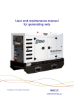
User and maintenance manual
for generating sets
R44C3
33504024301NE_0_1
1. Preface .................................................................................................................................................................................................. 3
1.1.
General recommendations ....................................................................................................................................................... 3
1.2.
Pictograms and their meanings................................................................................................................................................ 4
1.3.
Instructions and safety regulations ........................................................................................................................................... 6
1.3.1 General advice ......................................................................................................................................................................... 6
1.3.2 Risks related to exhaust gases and fuels ................................................................................................................................. 7
1.3.3 Risks related to toxic products .................................................................................................................................................. 7
1.3.4 Risk of fire, burns and explosion............................................................................................................................................... 8
1.3.5 Risks related to electrical networks .......................................................................................................................................... 8
1.3.6 Dangers presented by electric currents (first aid) ..................................................................................................................... 9
1.3.7 Risks related to moving the set................................................................................................................................................. 9
1.3.8 Risks related to noise .............................................................................................................................................................. 9
2. General description.............................................................................................................................................................................. 10
2.1.
Technical specifications ......................................................................................................................................................... 13
2.2.
Identifying sets ....................................................................................................................................................................... 15
2.3.
Fluid retention ........................................................................................................................................................................ 16
2.4.
Fuel and consumables ........................................................................................................................................................... 16
2.4.1 Specifications ......................................................................................................................................................................... 17
2.4.1.1.
Oil grades ................................................................................................................................................................. 17
2.4.1.2.
Specifications of coolants ......................................................................................................................................... 18
3. Installation-Connections ...................................................................................................................................................................... 19
3.1.
Unloading ............................................................................................................................................................................... 19
3.1.1 Safety during unloading .......................................................................................................................................................... 19
3.1.2 Instructions for unloading ....................................................................................................................................................... 20
3.2.
Choice of location .................................................................................................................................................................. 21
3.3.
Moving the genset .................................................................................................................................................................. 21
3.4.
Connections ........................................................................................................................................................................... 22
3.4.1 Connections - general information .......................................................................................................................................... 22
3.4.2 Power cables .......................................................................................................................................................................... 22
3.4.3 Power connections ................................................................................................................................................................. 23
3.4.4 Battery installation ................................................................................................................................................................. 24
3.5.
Protection for individuals and equipment ............................................................................................................................... 24
3.5.1 Earth connection..................................................................................................................................................................... 24
3.5.2 Earthing system principle ....................................................................................................................................................... 25
3.5.3 TT system ............................................................................................................................................................................... 26
3.5.4 Differential protection .............................................................................................................................................................. 26
3.5.5 Adjusting the genset differential protection ............................................................................................................................. 27
3.6.
Connection summary ............................................................................................................................................................. 28
3.7.
Special arrangements ............................................................................................................................................................ 29
4. Trailer .................................................................................................................................................................................................. 29
4.1.
Trailer linkage ........................................................................................................................................................................ 29
4.2.
Check before towing .............................................................................................................................................................. 29
4.3.
Operation ............................................................................................................................................................................... 30
4.4.
Unhitching the trailer .............................................................................................................................................................. 30
4.5.
Implementation for installation ............................................................................................................................................... 31
4.6.
Break transmission adjustment .............................................................................................................................................. 31
4.7.
Faults and repairs .................................................................................................................................................................. 33
4.8.
Electrical connection diagram ................................................................................................................................................ 34
4.9.
Complete wheels technical information .................................................................................................................................. 34
5. Preparation before operating the set ................................................................................................................................................... 35
5.1.
Installation checks.................................................................................................................................................................. 35
5.2.
Checks after starting the generating set ................................................................................................................................ 35
1/202
6. Using the generator set ....................................................................................................................................................................... 36
6.1.
Pre-Start Inspection ............................................................................................................................................................... 36
6.2.
Generator set with NEXYS control panel ............................................................................................................................... 39
6.2.1 Control panel presentation ..................................................................................................................................................... 39
6.2.1.1.
Introduction to pictograms......................................................................................................................................... 40
6.2.2 Manual starting ....................................................................................................................................................................... 41
6.2.3 Switching off .......................................................................................................................................................................... 42
6.2.4 Alarms and faults ................................................................................................................................................................... 42
6.2.5 Faults and alarms - Details ..................................................................................................................................................... 42
6.3.
Generator set with TELYS control panel ................................................................................................................................ 44
6.3.1 Control panel presentation ..................................................................................................................................................... 44
6.3.1.1.
View of the front panel .............................................................................................................................................. 44
6.3.1.2.
Description of the screen .......................................................................................................................................... 46
6.3.1.3.
Description of the pictograms in zone 1 .................................................................................................................... 47
6.3.1.4.
Description of the pictograms in zone 2 .................................................................................................................... 48
6.3.1.5.
Description of the pictograms in zone 3 .................................................................................................................... 49
6.3.1.6.
Display of messages in zone 4 ................................................................................................................................. 51
6.3.2 Starting ................................................................................................................................................................................... 55
6.3.3 Switching off .......................................................................................................................................................................... 56
6.3.4 Alarms and faults .................................................................................................................................................................... 56
6.3.4.1.
Viewing alarms and faults ......................................................................................................................................... 56
6.3.4.2.
Activation of an alarm or fault ................................................................................................................................... 57
6.3.4.3.
Activation of an alarm and a fault .............................................................................................................................. 58
6.3.4.4.
Engine fault codes display ........................................................................................................................................ 59
6.3.4.5.
Horn reset ................................................................................................................................................................. 60
7. Maintenance schedule ......................................................................................................................................................................... 60
7.1.
Reminder of use..................................................................................................................................................................... 60
7.2.
Maintenance safety instructions ............................................................................................................................................. 60
7.3.
Table of maintenance operations ........................................................................................................................................... 61
7.4.
Fault finding ........................................................................................................................................................................... 62
7.5.
No load and under load tests ................................................................................................................................................. 62
8. Battery ................................................................................................................................................................................................. 63
8.1.
Storage and transport ............................................................................................................................................................ 63
8.2.
Battery setting into service ..................................................................................................................................................... 64
8.3.
Check ..................................................................................................................................................................................... 64
8.4.
Load preconization ................................................................................................................................................................. 65
8.5.
Faults and remedies .............................................................................................................................................................. 66
9. Appendix .............................................................................................................................................................................................. 67
9.1.
Appendix A – Engine user and maintenance manual ............................................................................................................ 67
9.2.
Appendix B - Alternator user and maintenance manual .......................................................................................................165
2/202
1. Preface
1.1. General recommendations
Thank you for choosing an electrical generating set from our company.
This manual has been designed to help you operate and maintain your electrical generating set correctly.
The information contained in this manual is taken from technical data available at the time of print. In line with our policy of continually
improving the quality of our products, this information may be amended without warning.
Read the safety instructions attentively in order to prevent any accidents, faults or damage. These instructions must always be
followed.
You are likely to encounter several warning symbols in this manual.
This symbol indicates an immediate danger to human health and life in case of exposure. Failure to follow
the corresponding advice entails serious consequences for human health and life in case of exposure.
Danger
This symbol draws attention to the potential risks to human health and life in case of exposure. Failure to
follow the corresponding advice entails serious consequences for human health and life in case of exposure.
Warning
This symbol indicates a dangerous situation if the warning is not heeded.
Failure to follow the corresponding advice risks resulting in minor injury of personnel or damage to any other
object in case of exposure.
Important
In order to obtain optimum efficiency and the longest possible life for the electrical generating sets, maintenance operations must be
carried out according to the periods indicated in the attached preventative maintenance tables. If the electrical generating set is used
under dusty or unfavourable conditions, some of these periods will be shorter.
Ensure that all repairs and adjustments are carried out by personnel who have received appropriate training. Dealers have this
qualification, and can answer all of your questions. They can also supply you with spare parts and other services.
The left and right sides can be seen from the back of the electrical generating set (the radiator is at the front).
Our electrical generating sets have been designed so that damaged or worn parts can be replaced by new or reconditioned parts
thereby reducing the out of action period to a minimum.
For any replacement of parts, contact your nearest dealer for our company who will have the necessary equipment and can offer
properly trained and informed staff to carry out maintenance, parts replacement and even total reconditioning of generating sets.
Contact your local dealer for the available repair manuals and to make the necessary arrangements for training personnel in
implementation and maintenance.
Important
Some user and maintenance manuals for the engines fitted to generating sets cover control units and
include the start-up and shutdown procedures for the engines.
As the generating sets are fitted with control units that are specific to the generating sets, only the
information that appears in the documentation for the generating sets' control units should be taken into
consideration.
In addition, according to the manufacturing criteria of the generating sets, some engines may be fitted with
specific electrical wiring different to that described in the engine documentation.
3/202
1.2. Pictograms and their meanings
Safety notices are clearly mounted on the equipment to draw the operator's or maintenance technician's attention to the potential
dangers and explain the action to be taken in the interest of safety. These notices are reproduced in this publication for ease of
identification by the operator.
Replace any notice that is missing or illegible.
Publications delivered
with the generating set
must be referred to
Warning: risk of explosion
of
Protective
clothing
must be worn
Naked
flames
unprotected
prohibited.
No smoking
toxic
Your eyes and ears
must be protected
Entry prohibited to
authorised persons
Warning:
pressurised fluids
Periodic maintenance
must be carried out
Jet washing prohibited
Warning:
high
temperature, risk
of burns
Battery level must be
checked
Earth
Warning: rotating
or moving parts
(risk of getting
caught
in
the
machinery)
Lifting point required
Warning: corrosive product
Warning: danger
Warning: risk
electric shock
Warning:
materials
Figure 1.1: Pictograms and their meanings
4/202
and
lights
non-
Battery isolating
switch
Fuel
External fuel connections
Inspection hatch
Retention container
drainage
Fuel drainage
Oil drainage
Oil filling
Coolant filling
Coolant drainage
Forklift
lifting
Fuel supply selection valves
required
Bulk tank level high
for
During any operation on the
batteries, wear protective
glasses and protective clothing
Rinse any splashes of acid on the
skin or in the eyes using clean water.
Consult a doctor immediately.
Contaminated clothes must be
washed with water
Important: refer to the documentation accompanying the generating set.
Warning: emission of toxic exhaust gases. Do not use in a confined or badly
ventilated area.
Figure 1.1 ( continued ) : Pictograms and their meanings
5/202
1.3. Instructions and safety regulations
THESE SAFETY GUIDELINES ARE IMPORTANT
If you do not understand or have any questions about any point in this manual, contact your dealer who will explain it to you or give you
a demonstration. A list of risks and precautionary measures to take follows. You should also refer to any local and national regulations
that apply in accordance with your own jurisdiction.
KEEP THIS MANUAL
This manual contains important instructions which must be followed when installing or carrying out maintenance on a generating set or
batteries.
1.3.1 General advice
Use
The operating and safety instructions must be made known to operating personnel. They will be regularly updated.
Read and understand the manuals provided with the generating set, pump unit or lighting column properly. The manufacturer's
instructions must remain at the disposal of technicians, if possible in situ.
The facility must be operated under the direct or indirect supervision of a person appointed by the operator, who is familiar with the
operation of the facility, and the dangers and drawbacks of the products used or stored in the facility.
Do not wear loose clothing, or get close to machines in operation. Note that the fans are not clearly visible when the engine is
running.
Warn personnel present to keep their distance during operation.
Do not run the generating set, pump unit or lighting column without refitting the protective covers and closing all the access doors.
Never let a child touch the generating set, pump unit or lighting column, even when shut down.
Avoid operating the generating set, pump unit or lighting tower in the presence of animals (disturbance, scares, etc.).
Engage the parking brake when the generating set or lighting tower on its trailer is installed on the operating site. When chocking
the trailer on a slope; ensure that there is nobody in the path of the trailer.
Never start the engine without an air filter or exhaust.
Engine with turbocharger: never start the engine without fitting the air filter. The compressor wheel rotating inside the turbocharger
may cause serious bodily injury. Foreign objects in the inlet pipe may cause mechanical damage.
Engine with air preheating (starting components): never use a starting spray or any other similar starter assistance product. Upon
contact with the starting component, an explosion may occur in the inlet tube, causing bodily injury.
Do not touch the lighting column lights when they are switched on.
Maintenance
Follow the maintenance table and its instructions.
Always use tools in good condition which are suited to the work to be done. Ensure you have understood the instructions before
beginning any operation.
Goggles should be worn when carrying out maintenance operations and watches, bracelets etc. should be removed.
Fit only original parts.
Disconnect the battery and the pneumatic starter (if fitted) before undertaking any repairs, to prevent the engine from starting
accidentally. Fit a panel over the controls to prevent any attempt to start.
Only use the correct crankshaft turning techniques for turning the crankshaft manually. Do not try to turn the crankshaft by pulling it
or levering the fan. This method may cause serious bodily or material damage, or damage the vanes of the fan, reducing the
service life of the fan.
Clean off any trace of oil, fuel or coolant using a clean cloth.
Do not use a soapy solution containing either chlorine or ammonia, as these two chemicals prevent bubble formation.
Never use petrol or other inflammable substances to clean the parts. Use only approved cleaning solvents.
Do not use a high pressure cleaner for cleaning the engine and equipment. The radiator, hoses, electrical components, etc. may be
damaged.
Avoid accidental contact with parts at high temperatures (exhaust manifold, exhaust).
Before any maintenance operation on a lighting column light, cut the electrical power supply and wait for the bulbs to cool down.
Consumables
Observe regulations in force concerning use of fuel before using your generating set, pump unit or lighting tower.
Under no circumstances use seawater or any other corrosive or electrolytic product in the cooling circuit.
Environment
The operator must take the necessary measures to comply with the aesthetics of the site of use. The whole site must be maintained
in a good state of cleanliness.
The premises must be kept clean, and be regularly cleaned so as to avoid accumulation of dangerous materials or pollutants and
dust, which could ignite or cause an explosion. The cleaning equipment must be suited to the risks posed by the products and dust.
The presence of dangerous or combustible materials inside premises housing combustion devices shall be limited to the operating
requirements.
Facilities must be operated under the constant supervision of a qualified person, who must regularly check that the safety devices
are operating correctly and ensure that the combustion devices have the correct fuel supply.
Apart from the combustion devices, it is prohibited to use fire in any form. This restriction must be clearly displayed.
6/202
Spreading of waste water, sludge and waste is prohibited.
The fuels to be used must correspond to those featured in the declaration file and the specifications recommended by the
combustion device manufacturer.
The fuel is considered to remain in the same physical state as when it is introduced into the combustion chamber.
Burning of waste in the open air is prohibited.
Always protect your hands when checking for leaks. Pressurised liquids may penetrate body tissue and cause serious damage.
Risk of blood contamination.
Drain and dispose of engine oil in a specially provided container (fuel distributors can collect your used oil).
Except by special agreement, once closed, the gas supply main unit must only be re-opened by the gas distributor. However, the
user may access it under certain conditions. Check these for each site.
1.3.2 Risks related to exhaust gases and fuels
Danger
The carbon monoxide present in exhaust gases may cause death if the concentration levels in the air
breathed are too high.
Always use generating sets, pump units or lighting towers in a well-ventilated place where gases cannot
accumulate.
In case of indoor use:
Be sure to evacuate exhaust gases outdoors.
Provide appropriate ventilation so that personnel present are not affected.
Observe the local regulations in force for generating sets, pump units or lighting towers, as well as local regulations for use of fuel
(petrol, diesel fuel and gas) before using your generating set, pump unit or lighting tower.
Fuel filling should be carried out when the engine is off (except for generating sets with an automatic filling system).
Engine exhaust gases are toxic: do not run the generating set, pump unit or lighting column in unventilated premises. If installed in
a ventilated room, additional requirements for fire and explosion protection must be observed.
A leaking burnt gas exhaust may increase the sound level of the generating set, pump unit or lighting column. To check on its
efficiency, regularly examine the burnt gas exhaust.
Pipes must be replaced as soon as their condition demands it.
1.3.3 Risks related to toxic products
Glycol is a toxic product and dangerous if absorbed.
The corrosion inhibitor contains alkali.
Avoid all contact with the skin and eyes. Read the
Do not swallow it.
instructions on the packaging.
This substance should not come into contact with the
eyes. In the event of contact with the eyes, rinse
immediately with plenty of water for at least 15
minutes.
Avoid prolonged or repeated contact with the skin. In
the event of contact with the skin, wash thoroughly
with water and soap. CONSULT A DOCTOR
IMMEDIATELY. KEEP THE PRODUCT OUT OF
THE REACH OF CHILDREN.
Warning
The anti-rust product is toxic and dangerous if
absorbed. Avoid all contact with the skin and eyes.
Read the instructions on the packaging.
Caution: fuels and oils are dangerous to inhale. Ensure proper ventilation, and use a protective mask.
Never expose the equipment to liquid splashes or rainfall, and do not place it on wet ground.
The battery electrolyte is harmful to skin and especially eyes. If splashes get into eyes, rinse immediately with running water and/or
a 10% diluted boric acid solution.
Wear protective eyewear and strong base resistant gloves for handling the electrolyte.
7/202
1.3.4 Risk of fire, burns and explosion
The engine should not be operated in environments containing explosive products. As not all of the
electrical and mechanical components are shielded, there is a risk of sparks forming.
Danger
Make sure not to create sparks or flames, and not to smoke near the batteries, as the electrolyte gases are highly flammable
(especially if the battery is charging). Their acid also poses a risk to the skin, and in particular to the eyes.
Never cover the generating set, pump unit or lighting tower with any material during operation or just after shutdown (wait for the
engine to cool).
Do not touch hot parts such as the exhaust pipe, or put combustible materials on it.
Keep all flammable or explosive materials (e.g. petrol, oil, cloth, etc.) out of the way when the set is running.
Proper ventilation is required for your generating set, pump unit or lighting column to work properly. Without this ventilation, the
engine would very quickly rise to an excessively high temperature, causing accidents or damage to the equipment and to
surrounding property.
Do not remove the radiator cap if the engine is hot and the coolant is pressurised, due to risks of burns.
Depressurise the air, oil and cooling circuits before removing or disconnecting all the fittings, pipes or connected components.
Watch out for the possible presence of pressure when disconnecting a device from a pressurised system. Do not try to find
pressure leaks by hand. Oil at high pressure can cause bodily damage.
Some preservative oils are flammable. Also, some are dangerous to inhale. Ensure proper ventilation. Use a protective mask.
Hot oil causes burns. Avoid contact with hot oil. Check that the system is no longer pressurised before carrying out any procedures.
Never start or run the engine with the oil filler cap off (oil may splash out).
Never coat the generating set, pump unit or lighting column with a thin layer of oil to protect it from rust.
Never top up the oil or coolant if the generating set, pump unit or lighting column is running, or if the engine is hot.
A generating set can only operate when stationary, and cannot be installed on a vehicle or other mobile equipment, without a prior
study taking into account the various specific features of using the generating set.
1.3.5 Risks related to electrical networks
The electrical equipment supplied with the generating set complies with standard NF C15.100 (France), or with the standards of the
countries in question.
The earth connection must be installed in accordance with the standards in force in each country in question, and with the neutral
system sold.
Read the manufacturer's identification plate carefully. The values for voltage, power, current and frequency are shown. Check that
these values match the supply use.
Never accidentally touch stripped cables or loose connections.
Never handle a generating set with wet hands or feet.
Maintain electrical wires and connections in good condition. Using equipment in poor condition can lead to electrocution and
damage to equipment.
Always disconnect the power to the equipment or facility (generating set voltage, battery voltage and network voltage) before any
operation.
The electrical connections must be made in accordance with current standards and regulations in the country of use.
Do not use faulty, poorly insulated or provisionally connected wires.
Never reverse the positive and negative terminals on batteries when connecting them. This could cause severe damage to the
electrical equipment. Follow the wiring diagram supplied by the manufacturer.
The generating set should not be connected to any other power sources, such as the mains supply network. In specific cases
where there is to be a connection to existing electrical networks, this must only be installed by a qualified electrician, who should
take the operating differences of the equipment into account, according to whether the mains supply network or generating set is
being used.
8/202
Protection against electric shocks is ensured by an assembly of specific equipment. If this needs to be replaced, it should be by
components with identical nominal values and specifications.
If the protective plates (blanking covers) need to be removed to route cables, the protector (blanking cover) must be refitted when
the operations are finished.
Due to high mechanical stresses, use only strong flexible wiring with rubber sheathing, compliant with IEC 245-4, or equivalent
wiring.
1.3.6 Dangers presented by electric currents (first aid)
First aid
In the event of an electric shock, shut off the power immediately and activate the
emergency stop on the generating set or lighting column. If the voltage has not yet
been cut off, move the victim out of contact with the live conductor as quickly as
possible. Avoid direct contact both with the live conductor and the victim's body. Use
a dry plank of wood, dry clothes or other non-conductive materials to move the victim
away. The live wire may be cut with an axe. Take great care to avoid the electric arc
that will be generated by this.
Begin emergency procedures
Resuscitation
If breathing has stopped, begin artificial respiration at once in the same place the accident took place unless the victim or operator's life
could be endangered by this.
In the event of cardiac arrest, carry out cardiac massage.
1.3.7 Risks related to moving the set
To unload the generating sets, pump units or lighting columns from their transport support brackets under optimum safety and
efficiency conditions, you must ensure that the following points are observed:
The lifting machinery or equipment is suited to the work required, in good condition and with sufficient lifting capacity.
The slings are positioned in the rings provided for this operation, the forklift arms are resting fully underneath all of the base frame
cross-beams, or the lifting bars are inserted in the apertures provided for this purpose in the base to lift the entire generating set
(according to models).
For completely safe working conditions and to prevent damage to the components fitted on the upper edge of the set, pump unit or
lighting column, the generating set, pump unit or lighting column must be lifted up with an adjustable boom. All the chains and
cables must be parallel with each other, and as perpendicular as possible with the upper edge of the generating set, pump unit or
lighting column.
If other equipment fitted on the generating set, pump unit or lighting column alters its centre of gravity, special lifting devices may be
necessary to maintain correct balance and completely safe working conditions.
The ground must be able to withstand the load of the generating set, pump unit or lighting column and its lifting machinery without
stress (otherwise, put down beams of sufficient strength in a stable configuration).
Position the generating set, pump unit or lighting column as close as possible to its place of use or transport, in a clear space with
free access.
Never perform work on a generating set, pump unit or lighting tower just hanging from a lifting device.
1.3.8 Risks related to noise
Dangerous noise
Risk of hearing loss
Important
Prolonged exposure to a noise level above 80dB (A) can lead to permanent hearing damage.
Therefore, it is recommended that ear defenders are used when working in close proximity to a generating set which is in operation.
9/202
2. General description
Overview
2
4
1
5
6
3
Figure 2.1.1 : General description of the generating set
1
2
3
Acces to maintenance area
Lifting ring
Forklift grooves
4
5
6
Acces to control unit
Acces to power connections
Drawbar
10/202
1
6
4
2
5
3
Figure 2.1.2 : General description of the generating set
1
Protective grille
4
2
Battery isolating switch
5
3
Starter battery
6
Alternator
External fuel supply combined tap
(optional)
Charging alternator
11/202
Control
4
1
2
5
3
Figure 2.1.3 : General description of the generating set
1
2
3
Control unit
Emergency stop
Socket control panel
4
5
6
Note : Photo presented with the Nexys control unit.
12/202
Working hours counter
Power circuit breaker
Connection terminal block
6
2.1. Technical specifications
Range / Generating set type
RENTAL POWER / R44C3
Weights and Dimensions
Dimensions with high autonomy tank
Dimensions l x w x h
2200 mm x 1000 mm x 1528 mm
Weight:
1150 kg dry weight / 1350 kg in operating configuration
Hood:
M3127
Sound pressure level:
at 1 m: 73 dB(A)
measurement uncertainty : 0.70
Output
Emergency
Prime power 2
power 1
kW / kVA
kW / kVA
400/230
50
3
0.8
58
32 / 40
29 / 36
(1) ESP: Stand-by output available for emergency use under variable charge up to 200hrs per year as per lSO 8528-1, no overload available
under these service conditions.
(2) PRP: Main output available continuously under variable load for an unlimited time period per year as per ISO 8528-1, an overload of 10%
one hour every 12 hours is available, as per ISO 3046-1.
- Term of use :
Voltage
Hz
Phase
Max current (A)
Load factor
Standard reference conditions ESP/PRP 40° / 40°, Air Intlet Temp, 1000m / 1000m mA.S.L. 60 % relative humidity.
Engine data
Manufacturer / model
Type
Cylinder configuration
Cubic capacity
Rotation speed
prime power at nominal speed
Adjustment type
MITSUBISHI S4S-Z3DT61SD
4 Cycles Naturally aspirated
4 XL
3.33 L
1500 Rpm
36 kW
Mechanical
Fuel consumption
100 % main power
10.4 L/h
Fuel
Fuel type
High autonomy fuel tank
Diesel
220 L
Lubrication
Oil capacity
Min. Oil pressure
Nominal oil pressure
Oil consumption (100 % load)
Oil sump capacity
Type of lubricant
10 L
1 bar
3.9 bar
0.11 L/h
9L
Genlub
Cooling
Engine capacity with radiator
Max coolant temperature
Fan power
Refrigerant type
Thermostat
9.5 L
102 °C
0.8 kW
Gencool
76.5 – 90 °C
13/202
Alternator data
● Compliant with NEMA MG21 standards, UTE NF C51 111,
VDE 0530, BS 4999, IEC 34.1, CSA
Type
Number of phases
Power factor (cos Phi)
Number of poles
Excitation type
Insulation classe
Number of bearings
Coupling
● The alternator is protected against short circuits
● Vacuum impregnation, epoxy winding, IP23 protection rating
LEROY SOMER LSA43.2S159
3
0.8
4
AREP
H
1
Direct
Control unit(s)
NEXYS
Standard specifications:
Frequency meter, Voltmeter, Ammeter
Alarms and faults:
Oil pressure, Coolant temperature, Fail to start, Overspeed,
Alternator min/max, Fuel level low, Emergency shutdown
Engine parameters:
Working hours counter, Engine speed, Battery voltage, Fuel
Level, Air Preheating
TELYS
Standard specifications:
Voltmeter, Ammeter, Frequency meter
Alarms and faults:
Oil pressure, Water temperature, Start failure, Overspeed,
Alternator min/max, Battery voltage min/max, Emergency stop
Engine parameters:
Timer, Oil pressure, Water temperature, Fuel level, Engine
speed, Battery voltage
14/202
2.2. Identifying sets
Generating sets and their components are identified by means of identification plates.
The precise rules for identifying each major component (engine, alternator etc.) are set out in each manufacturer's documentation
contained in the appendices of this manual.
1 - Generating set
2 - Manufacturer name
3 - Model
4 - Serial number
5 - Year of manufacture
6 - Rated output (kVA and kW) according to the ISO
8528-1 standard
PRP: main power
ESP: emergency power
7 - Rated power factor
8 - Maximum altitude of the site above sea level (m)
for the rated power
9 - Maximum ambient temperature for the rated power
(°C)
10 - Rated frequency (Hz)
11 - Generating set rotation speed (RPM)
12- Rated voltage (V)
13 - Rated current (A)
14 - Weight (kg)
15 - CE marking
16 - Non CE standard marking e.g.: GOSSTANDART)
17 - Sound pressure
18 - Sound power
Figure 2.2: Example of generating set identification plate
15/202
2.3. Fluid retention
Any outflow of the fluids contained in the generating sets (fuel, oil and coolant, or rainwater or condensation) will be collected in a
retention container.
The containers have a capacity which allows 110% of the fluids contained in the generating set fitted with this option to be collected.
Diagram 2.3: Fluid retention container
The generating sets are fitted with a visual alarm warning when the upper limit of the retention container has been reached.
In all cases, the retention containers must be regularly checked to ensure they contain no fluid (fuel, oil and coolant, or rainwater or
condensation). If necessary, drain the containers via the drain port.
Note: Never allow these fluids to drain onto the ground; ensure they are collected in a designated container.
2.4. Fuel and consumables
All specifications (product features) are given in the engine maintenance manuals attached to this manual.
Fuels:
The specifications refer to European or international standards. Fuels complying with the standards indicated in the engine
maintenance manuals can be used without any contraindications. Only these fuels may be used.
Consumables:
In addition to the specifications indicated in the engine maintenance manuals, the consumables mentioned in the section entitled
"Specifications" are recommended.
16/202
2.4.1 Specifications
2.4.1.1.
Oil grades
Engine
Oil
Make
Type
John Deere
All
MITSUBISHI
Volvo
All
All
Make
John Deere
GenPARTS
GenPARTS
GenPARTS
Type
John Deere PLUS-50
GENLUB TDX 15W40
GENLUB TDX 15W40
GENLUB TDX 15W40
GENLUB TDX 15W-40
Top-of-the-range lubricant recommended for diesel engines: for generating sets used under severe conditions.
USES:
Particularly suited to more modern engines with or without turbochargers, intercoolers, or sophisticated injection systems (e.g.
HEUI, injector-pumps).
All types of use: can cope with the most demanding applications.
Depolluted engines: complies with EURO 2 and EURO 3 technology and can be used with all types of diesel fuel, especially
ecological diesel with low sulphur content.
PERFORMANCE:
ACEA E3
API CH-4
Meets level E3 of the specifications defined by European manufacturers in the ACEA standards 98 edition.
ADVANTAGES:
Less frequent oil services: this product has been put to the test during thousands of hours of use on worksites under varying
conditions, demonstrating its high quality.
Conformity with new environmental legislation: adherence to new anti-pollution standards required for new EURO 2 and
EURO 3 engines.
SPECIFICATIONS:
SAE Grade
15W-40
Density at 15°C
Cinematic viscosity at 40 °C
Cinematic viscosity at 100 °C
Viscosity index
Dynamic viscosity at -15 °C
Pour point
Flash point
Sulphated ash content
(Values given as examples only)
0.883
105
14.1
mm2/s (cSt)
mm2/s (cSt)
140
3000
- 30
220
1.4
mPa.s(cP)
°C
°C
% weight
17/202
2.4.1.2.
Specifications of coolants
Engine
Coolants
Make
John Deere
Type
All
MITSUBISHI
All
Volvo
All
Make
GenPARTS
Mitsubishi
GenPARTS
GenPARTS
Type
GENCOOL PC -26°C
LLC
GENCOOL PC -26°C
GENCOOL PC -26°C
GenCOOL PC -26
High-protection coolant, approved by manufacturers.
GenCOOL PC -26 is a ready-to-use, highly protective coolant which is produced from an antifreeze recommended by the majority of
European manufacturers.
It is made from antifreeze and G 48 inhibitors.
It protects up to -26°C.
It is free from nitrates, amines and phosphates.
It is a clear, fluorescent orange liquid.
REFERENCES/APPROVALS (for the antifreeze):
HEAVY GOODS VEHICLE
Approved by MTU, MERCEDES BENZ, MAN,
GENERAL MOTORS
LIGHTER VEHICLES
KHD, Approved by BMW, VOLKSWAGEN, MERCEDES, PORSCHE
Conforms with
Conforms with VOLVO, IVECO, VAN HOOL and STAYR specifications
TRUCK specifications
VOLVO,
OPEL,
SEAT
and
SKODA
Conforms with the NF R 15.601 standard
REINFORCED ANTI-CORROSION FEATURES:
Protects against high-temperature corrosion by oxidisation of ethylene (cylinder head protection).
Protects against high-temperature cavitation (top of cylinder and coolant pump protection).
Non-corrosive for seals and hoses.
Improves the efficiency and longevity of the cooling system.
GenCOOL PC -26 is especially recommended for engines fitted with aluminium or light alloy radiators.
HIGH TEMPERATURE SUITABILITY:
Provides good conditions for thermal exchange.
Perfect stability at high temperatures.
GenCOOL PC -26 is specially adapted for engines with high power densities.
LONG LASTING PROTECTION:
High alkaline reserve/stability and longevity of corrosion inhibitors.
Maintains its technical properties during prolonged use at high temperatures (neutralisation of acids).
Ensures maximum heat transfer without the build up of deposits in the cooling system.
GenCOOL PC -26 ensures optimum protection against overheating and corrosion in extreme conditions of vehicle use.
18/202
PACKAGING/STORAGE:
GenCOOL PC -26 is supplied in 210 l metallic barrels with smooth interior linings.
It can be stored for 2 years in its original container and packaging.
Avoid zinc coated containers.
RECOMMENDATIONS FOR USE:
Compatible with the original fluid.
It is recommended that the cooling system is completely drained when replacing the fluid.
UNITS
SPECIFIED VALUES
TRIAL
METHODS
kg/m3
1,059 +/- 3
R 15-602-1
pH
pH
7.5 to 8.5
NF T 78-103
Alkalinity reserve
ml
>=10
NF T 78-101
Boiling point
°C
105 +/- 2
R 15-602-4
°C
-26 +/- 2
NF T 78-102
SPECIFICATIONS
Density at 20°C
Freezing point:
Glassware
corrosion
(test with antifreeze)
:
mg/test piece
R 15-602-7
- Copper
+/- 2.6
- Weld
+/- 0.5
- Brass
+/- 2.3
- Steel
+/- 1.6
- Cast iron
+/- 0.8
- Cast aluminium
Corrosion on warm
(test with antifreeze)
+/- 1.0
plate
+/- 0.17
mg/(cm²week)
R 15-602-8
3. Installation-Connections
3.1. Unloading
3.1.1 Safety during unloading
To unload electrical generating sets from their transport supports with optimum safety and efficiency, you must ensure that the
following points are observed:
-
The lifting machinery or equipment is suitable for the work required.
The sling is correctly positioned in the central lifting eye or the lifting arms are correctly positioned in the fork-lift pockets intended
for this purpose.
- The ground is able to bear the load of the generating set and its lifting machinery without stress (otherwise lay down stabilising
beams of sufficient strength).
- The generating set is put down as close as possible to its place of use or transport, in a clear space with free access.
Example of equipment to be used:
crane, slings, lifting beam, safety hook, shackles.
Forklift truck.
19/202
3.1.2 Instructions for unloading
Hoisting
Attach the sling on the lifting equipment to the ring on the generating set (no. 1) provided for this purpose. Tension the slings
slightly.
Check that the sling is correctly attached and the equipment is steady.
Lift the generating set carefully.
Direct the generating set towards the chosen location and stabilise it.
Carefully set down the equipment while continuing to position it.
Release the sling, then detach it.
Forklift truck:
Position the arms of the forklift truck in the forklift pockets (no. 2).
Lift the equipment, handling it gently.
Set down the generating set in its unloading position.
1
2
20/202
3.2. Choice of location
This shall be determined according to the application. There are no strict rules governing the choice of location, other than the proximity
of the electrical supply panel and the disturbance caused by the noise. However, it is important to take into account the fuel supply, the
evacuation of burnt gases, the direction of these gases and evacuation noises.
The choice of location will therefore be the result of a carefully considered compromise!
Examples of problems that may be encountered:
Incorrect ventilation and exhaust
Building or terrain too rough.
Generating set incorrectly seated
Impossible to fill with fuel
Reduced access
Impossible to open enclosure doors
Figure 3.1: Examples of problems that may be encountered
Ensure that the generating set is placed on a flat surface.
Warning
3.3. Moving the genset
Whenever the generating set is moved, the appropriate equipment must be used (sling, forklift, etc.) and you must know the parts of
the generating set which enable it to be moved ( see below).
Central lifting ring
Forklift pockets
21/202
Drawbars
3.4. Connections
3.4.1 Connections - general information
As with low voltage electrical installations, use and maintenance is governed by standard NFC 15.100 (France) or by the standards in
the relevant country, based on international standard IEC 60364-6-61.
They must also adhere to the regulations in the NFC 15.401 application guide (France) or to the regulations and standards in the
relevant country.
3.4.2 Power cables
These can be unipolar or multipolar according to the power of the generating set.
Power cables should preferably be installed in ducts or on a cable tray for this purpose.
The cable cross-section and number of cables should be determined according to the cable type and the current standards to be
observed in the country of installation. The choice of conductors must comply with international standard IEC 30364-5-52.
Three phase - Calculation hypothesis
Fitting method = wiring in cable runs or non perforated trays.
Permissible voltage drop = 5%
Multiconductors or single conductor joined when precision 4X…(1)
Cable type PVC 70°C (e.g. H07RNF).
Ambient temperature = 30°C.
Cable sizes
Circuit breaker
calibre
(A)
10
16
20
25
32
40
50
63
80
100
125
160
250
400
630
(1)
(1)
(1)
(1)
(1)
0 - 50m
mm²/AWG
1.5 / 14
2.5 / 12
2.5 / 12
4 / 10
6/9
10 / 7
10 / 7
16 / 5
25 / 3
35 / 2
4X(1X50) / 0
4X(1X70) / 2/0
4X(1X95) / 4/0
4X(1X185) / 0400MCM
4X(2X1X150) / 2x 2350MCM
51 - 100m
mm²/AWG
2.5 / 12
4 / 10
4 / 10
6/9
6/9
10 / 7
10 / 7
16 / 5
25 / 3
35 / 2
4X(1X50) / 0
4X(1X70) / 2/0
4X(1X150) / 2350MCM
4X(1X185) / 0400MCM
4X(2X1X150) / 2x 2350MCM
101 - 150m
mm²/AWG
4 / 10
6/9
6/9
10 / 7
10 / 7
16 / 5
16 / 5
25 / 3
35 / 2
4X(1X50) / 0
4X(1X70) / 2/0
4X(1X95) / 4/0
4X(1X150) / 2350MCM
4X(1X185) / 0400MCM
4X(2X1X150) / 2x 2350MCM
Single phase - Calculation hypothesis
Fitting method = wiring in cable runs or non perforated trays.
Permissible voltage drop = 5%
Multiconductors.
Cable type PVC 70°C (e.g. H07RNF).
Ambient temperature = 30°C.
Cable sizes
Circuit breaker
rating (A)
10
16
20
25
32
40
50
63
80
100
125
0 - 50m
51 - 100m
101 - 150m
mm²/AWG
4 / 10
6/9
10 / 7
10 / 7
10 / 7
16 / 5
16 / 5
25 / 3
35 / 2
35 / 2
50 / 0
mm²/AWG
10 / 7
10 / 7
16 / 5
16 / 5
25 / 3
35 / 2
35 / 2
50 / 0
50 / 0
70 / 2/0
95 / 4/0
mm²/AWG
10 / 7
16 / 5
25 / 3
25 / 3
35 / 2
50 / 0
50 / 0
70 / 2/0
95 / 4/0
95 / 4/0
120 / 2250MCM
22/202
3.4.3 Power connections
Disconnect the battery leads or use the battery isolating switch before carrying out any operations
on the generating set.
(To disconnect the battery, disconnect the negative lead (-) first).
Warning
1.
2.
3.
4.
Open the access hatch to the power section.
Feed the power cables through the access hatch on the genset control unit.
Connect the power cables to the bars. (N/L0-L1-L2-L3 or N2-R2-S2-T2).
Connect the power cables to the installation ensuring the live and neutral wires are correctly connected.
Acces hatch
N/L0 L1
or
N2
or
R2
L2 L3
or
or
S2 T2
USE
Ensure that the direction of rotation of the phases is identical on the genset and the installation.
(Our gensets are factory-set with a conventional direction of phase rotation)
Warning
23/202
3.4.4 Battery installation
Install the battery or batteries in the immediate vicinity of the electric starter motor. The cables will be connected directly from the
battery terminals to the starter motor terminals.
The primary instruction to follow is to ensure that the polarities between the battery and starter motor match. Never reverse the positive
and negative battery terminals when connecting them. This could cause severe damage to the electrical equipment.
2
The minimum cross-section of the cables will be 70 mm . It varies according to the power of the starter motor but also the distance
between the batteries and the set (voltage drops on the line).
3.5. Protection for individuals and equipment
3.5.1 Earth connection
For effective protection against electric shocks, the generating set needs to be earthed. To do this, use a copper wire, with a minimum
cross-section of 25 mm2 for a stripped cable and 16 mm2 for an insulated cable, connected to the generating set earth socket and a
galvanised steel earthing rod embedded vertically into the ground.
generating set earth socket
The earthing rod resistance value should comply with the values shown in the table below.
Note: use the highest differential setting from the installation as a guideline.
The resistance value is calculated in the following way:
R = Ul
I Δn
Maximum resistance value of the earth socket R (Ω) according to the differential unit operational
current (operation time should not be longer than 1 second).
I Δn
differential
≤ 30 mA
100 mA
300 mA
500 mA
1A
3A
5A
10A
Earth R
(Ω)
Ul: 50 V
500
500
167
100
50
17
10
5
Earth R
(Ω)
Ul: 25 V
> 500
250
83
50
25
8
5
2.5
The Ul value: 25 V is required for work site installations, and livestock buildings, etc.
24/202
For a default voltage of 25 V and a default current of 30 mA, this rod must be of a minimum length of: see table below
Length of
rod in
metres
Nature of ground
Thick arable land,
moist compact ballast
Lean arable land,
Gravel, coarse ballast
1
1
Bare stony soils, dry sand,
impermeable rock
To obtain an equivalent length, you can use several earthing rods
connected in parallel and set apart by at least their length.
Example: 4 interconnected 1 metre rods separated by 1 metre.
3.6
Note: For the United States (National Electrical Code reference NFPA-70).
The generating set must be earthed. To do this, use a copper wire with a minimum cross-section of 13.3 mm² (or AWG 6, at most)
connected to the generating set earth socket and a galvanised steel earthing rod fully embedded into the ground vertically.
This earthing rod embedded fully in the ground must have a minimum length of 2.5 m.
3.5.2 Earthing system principle
The Earthing system, or SLT (formerly Neutral system) of the electrical facility defines the situation of the generating set neutral in
relation to earth and the grounds of the electrical facility at the user end.
The purpose of the earthing systems is to protect personnel and equipment by managing risks posed by insulation defects. For safety
reasons, any live conducting part of a facility must be insulated from the earth. This insulation may be achieved by distance, or by using
insulating materials. But with time, insulation may deteriorate (due to vibrations, mechanical impacts, dust, etc.), and therefore generate
an earth with dangerous potential. This defect poses risks for personnel and property, but also continuity of service.
Earthing systems are codified by two letters that define the connections:
The first letter defines the neutral connection:
I
Insulated or earthed via an impedance device
T
Connected to earth
The second letter defines the grounding situation of the electrical facility:
T
Connected to earth
N
Connected to neutral
E.g.: IT = Isolated Neutral + Ground earthed
Number of
conductors
Speed
TT
TN
C
S
4 poles
3 poles
4 poles
IT
SN
3 poles
Detection
Note
Measurement of residual current
Triggering of 1st fault by RCD
Triggered by overcurrent protection
upon 1st fault
nd
Triggered upon 2 fault by
overcurrent protection
No measurement of residual current
Insulation resistance measurement
25/202
3.5.3 TT system
R
R
Ph 1
Ph 1
Ph 2
Ph 2
id
Ph 3
Ph 3
N
N
PE
PE
id
R
R
R
Neutral connected
to earth T
Ground connected
to earth T
Neutral
earth
id
Ground
earth
Figure 3.2: TT neutral system.
The alternator neutral is earthed, and the grounds of the user equipment have their own earth connection.
In the TT system, automatic power cut-off via a Residual Current Device (RCD) is obligatory at the upstream part of the facility, to
ensure protection of personnel (with a maximum 30 mA device on outlet circuits).
3.5.4 Differential protection
In order to ensure that people are protected from electric shocks from the TT system, the generating set is equipped with a residual
current device: this can be fixed or adjustable depending on the option chosen.
• If the generating set's residual current device is not adjustable and the activation threshold has been set at 30 mA, all terminal
circuits in use are protected.
• If the generating set's residual current device is not adjustable and the activation threshold has been set at 300 mA, a 30mA
residual current device must be added to each of the circuit outlets in use.
•
If the generating set's residual current device is adjustable, (located upstream) this must be above those devices located
downstream (terminal circuits); this means that continuity on clean circuits will be maintained in the event of a fault on one of
the terminal circuits.
Generating set
Example:
300mA
30mA
Important
Residual current device
30mA
Terminal circuit 1
Generating set's
current device
residual
Residual current device
30mA
Terminal circuit 2
Residual current device
Terminal circuit 3
Any change to the setting on the generating set's residual current device could pose a risk to personal safety.
The user will be held liable - any changes must only be made by trained, qualified engineers.
When the generating set is disconnected from an installation after use, the general residual current device
must be restored to factory settings by a qualified engineer who can then check this.
26/202
3.5.5 Adjusting the genset differential protection
Before adjusting the settings on the generating set's residual current device, the following two parameters must be taken into account:
the sensitivity of the current threshold and the activation time.
The generating set's residual current device must have, in relation to the downstream device (terminal circuit):
- a sensitivity three times greater.
- a longer cut-off time.
Type A/AC
Type B
Time setting potentiometer
Current threshold adjustment potentiometer
Two types of differential relay are fitted on the generating sets:
Type A:
Differential device for which operation is guaranteed:
for residual sinusoidal alternating currents,
for continuous pulsed residual currents,
for continuous pulsed residual currents with a continuous component of 0.006 A with or without phase check, independent of
the polarity.
Type B:
Device for which operation is guaranteed:
as in the case of type A,
for residual sinusoidal currents up to 1000 Hz,
for residual sinusoidal currents superimposed on a pure continuous current,
for continuous pulsed currents superimposed on a pure continuous current,
for residual currents which could come from rectifier circuits i.e.:- three phase half-wave rectifier or a three-phase full-wave
bridge rectifier, full-wave bridge rectifier between phases, with or without phase angle check, independent of the polarity.
Our residual current devices are factory-set with an activation threshold of 30 mA and with automatic cut-off. Depending on the use, if
the residual current device is modified, it is recommended to fit a seal to prevent any tampering when the generating set is being used.
27/202
Identify its earthing system
3.6. Connection summary
Option « Application EDF »
France uniquement
TT
Mark the type of differential protection
Fixed genset differential protection
Adjustable genset differential protection
30 mA
300 mA
30 mA
300 mA
No operation required:
terminal circuits protected
Add differential protection
set to 30 mA to the terminal
circuit output(s)
No operation required:
terminal circuits protected
Add differential protection
set to
30 mA to the terminal circuit
output(s)
Earth the generating set
Connect to the power supply
28/202
3.7. Special arrangements
Generating sets are not fitted with protection against power surges caused by drops in atmospheric pressure or manoeuvring.
The company does not accept any responsibility regarding damage caused by these occurrences.
However, lightning conductors can be installed, on the understanding that this does not give total protection.
4. Trailer
4.1. Trailer linkage
Before attaching the trailer, check the trailer hook on the tow vehicle; it should fit the trailer ring perfectly.
Warning
Trying to tow a trailer with a non-matching device (bar, wires, cords, etc.) could lead to serious
accidents.
Also check:
- no incipient fractures or excessive wear on the hitching system.
- locking system is operating properly.
To hitch the trailer, proceed as follows:
Lock the wheels to stop the trailer from moving
Lift up the rear trailer supports and lock them
Release the parking brake
Release the locking levers for the draw bar arms and adjust the ring to the same height as the vehicle hook
Hitch the trailer, remove the locks on each side of the wheels then lift up the front wheel fully using its handle
Connect the electrical circuit of the trailer to that of the tow vehicle
Hook the handbrake safety wire onto the hook on the tow vehicle.
CORRECT
CORRECT
Tow vehicle
Tow vehicle
Trailer
Trailer
INCORRECT
INCORRECT
Tow vehicle
Tow vehicle
Trailer
Trailer
Diagram 4.1 : Coupling a trailer
4.2. Check before towing
Before towing, check the following:
Tightness of the generating set enclosure bolts.
Wheel tightness.
Hitching hook locked.
Tyre pressure.
Signalling lights working, for "on-road" trailers.
Enclosure doors closed.
Parking brake released, for "on-road" trailers.
Guide wheels (jockey wheels) and stands lifted (if fitted).
Towbar arm locking levers tightened and pinned (if fitted with an adjustable towbar).
Brake test, for "on-road" trailers.
Safety cable fitted, for "on-road" trailers.
29/202
4.3. Operation
"On-site" trailer
These trailers are not fitted with a main brake, and so cannot be braked in motion; the tyres allow for a maximum speed of 27 km/h. So
it is absolutely prohibited to exceed this speed.
Nor are these trailers fitted with signalling lights. On-road use is prohibited.
"On-road" trailer
The driving speed must be suited to the condition of the road and the handling of the trailer.
Driving at high speed causes heating of the tyres; so it is important to stop from time to time, and check them. Excessive heating may
cause a puncture, and therefore a serious accident. For reversing manoeuvres, remember to lock the inertia brake.
Particular attention must be paid to the tightness of the wheels on new vehicles.
In the first few miles' driving, heating of the brake hubs and drums will actually reduce the wheel tightness. It
is therefore essential to check the tightness every 6 miles (10 kilometres) until no further loosening is noted.
Nonetheless the tightness must be checked whenever you are about to tow the trailer.
Warning
Lights/signalling (only for "on-road" trailers)
Warning lights are obligatory for on-road driving. Signalling must comply with regulations in force in the country of use.
Front reflective devices (white)
Red rear lights + direction indicators+ stop lights
Rear reflective devices (red triangle)
Side reflective devices (orange)
Figure 4.2: Example of French signalling
4.4. Unhitching the trailer
This operation should be carried out on horizontal, flat, stable ground.
Lock the wheels
Lower the front wheel
Disconnect the road signals wire
Refit the hitch using the wheel to release the hook ring from the tow vehicle,
Release the tow vehicle
Engage the handbrake.
30/202
4.5. Implementation for installation
Operations to be carried out:
Ensure that the ground is strong enough for the assembly not to sink into it.
Unhitch the trailer.
Immobilise the trailer by placing chocks under the wheels.
Fully engage the parking brake (if fitted).
Using the front wheel, position the generating set as close to horizontal as possible.
Lower the stands (if fitted), and lock them.
4.6. Break transmission adjustment
- The handbrake is used only as a parking brake.
- Setting is carried out starting with the brakes moving to the brake control.
Important
After fitting the wheels on the axle, turn the wheels in the FORWARD direction (on all RA 2 type brakes, check that the adjustment
screw 8 reaches the “FORWARD” stop on the brake backing plate).
Adjust the brake setting using screw 8, with the cables not connected to the cross bar(s). The shoes should rub the drum slightly.
Connect the brake cables to the cross bars(s) and tighten the nuts and lock nuts, leaving the end of the threaded end protruding
by around 10 mm (Fig. 4.4).
IMPORTANT: Wherever possible, cables must cross over to achieve the highest possible gain curve (Fig. 4.5).
Check that the parking lever 1 is in the ‘REST” position and that the compensating spring 4 is completely free on its rod (unscrew
the nuts 5 fully).
Check that the hook slide 2 is not compressed and the yoke 3 is in the pulled out position.
Fit the transmission and adjust the assembly using the tensioner 6 until a gap (J1) of 1 mm max is obtained between the linkage 9
and slide 2.
Adjust the compensating spring 4 at one end pressing it against the anchorage plate, and at the other end leaving a 2 mm gap (J2)
max between the spring and nuts 5.
Tighten all the lock nuts.
Checking the setting (trailer on axle stands):
Pull the parking lever 2 notches - the wheels cannot turn in a FORWARD direction.
The wheels can turn in REVERSE (adjustment screw 8 switches to the REAR position).
Pull the parking lever fully.
The wheels will not turn either in FORWARD or REVERSE and the cross bar(s) must remain parallel with the axle body.
Check the transmission setting after 180 miles (300 km) (running in period) and if necessary adjust the gap (J1) using the
tensioner.
Parking
The lever must be fully pulled up, so that the compensating spring is fully compressed.
Every 900 miles (1500 km), check the braking settings and distribution on all the wheels.
Important
The brake controls are designed to draw trailers behind flexible suspension touring vehicles. If used behind an HGV, be sure
to provide the fitted ball joint with a shock absorber to prevent premature wear.
During any manoeuvres with the trailer coupled, do not turn more than 90° or force reverse.
The specifications of our brake controls are indicated on a manufacturer's plate, and the items on this should be supplied to us
when requesting replacement parts, in particular for the shock absorber, of a special type, approved by the Service des Mines
to correspond to European standards (it is advisable to have a spare shock absorber to enable instant repairs).
31/202
Figure 4.3: Braking transmission
Figure 4.4: Cross bar fitting
Figure 4.5: Tandem bearing fitting
32/202
4.7. Faults and repairs
Fault observed
Erratic braking of trailer
Braking too weak
Drum temperature abnormally high
Jerky braking
Origin
- Faulty shock absorber
- Jaws worn
- Jaws not run in
- Incorrect linkage setting
- Significant friction on the slide
- Slide corrosion
- Coupling height does not match that of
the towing vehicle
- Incorrect linkage setting
- Incorrect brake setting
- High levels of dust in the drums
- Jaws, springs, drums damaged
- Brake cables or link rod damaged
- Incorrect linkage setting
- Interfering parts on the slide
- Corroded slide
- Damage to slide guide rings
- Faulty shock absorber
- Cross-bar(s) not balanced
- Different brake setting on the two sides
Trailer tending to swerve upon braking
- Cables damaged or incorrectly fitted
- Poor load distribution
- Damage to slide or to guide rings
- Slide corrosion
When starting the trailer holds back the
towing vehicle
- Tie rod damaged
- Linkage damaged or incorrectly set
Play in the coupling head
Parking braking too weak
- Brake on
- Head worn (see wear indicator)
- Ball joint worn
- Compensating spring incorrectly set
- Braking system incorrectly set
- Notched sector damaged
- Lever ratchet worn
- Cable ruptured
33/202
Solutions
Replace the shock absorber
Replace the jaws
Fault will disappear only after running in
Adjust the setting
Grease the sliding parts
Remove the corrosion and grease
Adjust the height so that the two parts
are in the same horizontal plane
Adjust the settings
Adjust the settings
Remove the dust
Replace the damaged parts
Replace the damaged parts
Adjust the settings
Remove, clean and grease
Remove the corrosion and grease
Replace the rings (and possibly the
slide) and grease
Replace the shock absorber
Adjust the cross-bar(s)
Adjust the brake settings
Replace the damaged parts
Refit the cables
Check the load distribution
Replace the faulty parts and grease
Remove the corrosion and grease
Replace the tie rod and adjust the
settings
Replace the damaged parts and adjust
the settings
Loosen the brake
Replace the head
Replace the ball joint
Adjust the setting
Adjust the setting
Replace the sector and adjust the
setting
Replace the lever and adjust the setting
Replace the cable and adjust the setting
4.8. Electrical connection diagram
Figure 4.6 : Electrical connection diagram
4.9. Complete wheels technical information
TYRES
Dimensions
Indices
Diameter (mm)
Cross section
(mm)
135 R 13
145 R 13
155 R 13
145/70 R 13
155/70 R 13
185/70 R 13
165 R 14 C
155/70 R12
70 T
75 T
79 T
71 T
75 T
86 T
98 N
100 N
550
566
578
534
548
594
622
525
134
145
150
150
147
185
172
155
Radius under
load
(mm)
265
272
277
259
263
285
284
244
185 R 14 C
102 P
650
188
316
198
190
32
-
195 R 14 C
195/50 x 10
(1)
Wheel with 4 holes
106 P
666
98 N
450
(2)
Wheel with 5 holes
34/202
COMPLETE
WHEELS
Load
Pressure
(Kg)
(bar)
335
387
437
345
387
530
650
650 (1)
(2)
800
675 (1)
(2)
850
950
750
2.4
2.4
2.4
2.5
2.5
2.5
3.8
6.25
4.5
4.5
6.0
5. Preparation before operating the set
The inspections referred to in this section enable the electrical generator set to operate.
Specific skills are required to carry out these operations.
They must only be entrusted to personnel with the necessary skills.
Failure to follow these instructions in any way could result in malfunction or very serious accidents.
Danger
5.1. Installation checks
•
•
•
•
•
Check that the general recommendations from section "Installation" (ventilation, exhaust, connections, etc.) are followed.
Carry out level checks (oil, coolant, diesel, battery).
Ensure that the generating set is correctly earthed (earthing rod).
Ensure that the electrical connections have been made properly.
Ensure that the fuel connection has been made properly (valve position), if the generating set is equipped with the three-way valve
option enabling external supply.
5.2. Checks after starting the generating set
•
•
•
•
Carry out the mechanical checks (oil pressure, water temperature, absence of noise, etc.).
Carry out the electrical checks (voltage, current, frequency, rotary field, etc.).
Carry out the safety checks (emergency shutdown, oil pressure, coolant temperature, etc.).
Carry out the check on Normal/Emergency Inverter switching or coupling (if fitted).
35/202
6. Using the generator set
6.1. Pre-Start Inspection
•
Inspecting the engine compartment
Make sure there is no combustible material near the engine or battery. Also, check to
make sure that the engine and battery are clean. If combustible materials or dust are
found near the engine or battery, remove them.
Check the electrical wiring for such components as the starter and alternator for
looseness
Check the entire engine for fuel leakage, engine oil or coolant. If leakages are found,
repair.
Make sure the following valves, plugs and cocks are open or closed (tightened) properly:
Fuel feed valve: Open
Coolant drain cock (plug): Closed (Tightened)
Oil drain valve: Closed
•
Checking the engine oil level
- Do not top up the oil if the oil level is not below the low level marker.
Important
Pull out the oil level gauge and wipe it clean using a waste cloth.
Insert the oil level gauge fully into the oil level gauge guide, then pull out the gauge again.
The proper oil level is between the high and low marks on the oil level gauge. If the oil level is low, add engine oil of the specified
type.4. Install the oil filler cap after refilling.
Check the oil pan and other area for oil leakage.
36/202
•
Checking the coolant level
Warning
Remove the radiator filler cap only after the engine has cooled to room temperature. Place a waste cloth
over the cap, and loosen the cap about a half-turn or stand the lever to the upright position to release
internal pressure. Never open the radiator filler cap while the engine is hot, otherwise the steam or hot
coolant spurts out and you may be scald with it.
Open the radiator filler cap and check the coolant level.
If the coolant level is low, add coolant to the speci-fied level.
Check for leaks in the cooling circuit.
•
Checking the air filter
A clogged filter element limits the engine's air intake and a reduced air supply to the engine.
Important
If the air filter is fitted with a dust control valve (A), press the tip
of the valve to evacuate any accumulated dust particles.
B
Check the air filter clogging indicator (B). If the indicator is red,
clean the air filter.
A
37/202
•
Checking the fuel filters
When handling fuel, make sure there are no open flames or other fire hazards near the engine. Wipe
off any spilled fuel completely.Spilled fuel can ignite and cause a fire.
Danger
Drain water for the fuel filter if the warning of water draining for fuel filter is occurred.
Place a drip tray under the drain hose.
Loosen the drain plug and drain water from the fuel filter.
Feed fuel by pushing down on the priming pump (about seven strokes) to facilitate draining.
After draining, tighten the drain plug securely.
After drain the fuel filter, bleed the fuel system.For bleeding air from fuel system.
For bleeding air from fuel system:
Loosen the air vent plug on the fuel filter about 1.5 turns.
Apply a cloth to the air vent plug.
Repeat pumping until the fuel flow from air vent plug becomes free of bubbles.
Tighten the air vent plug and clean.
38/202
6.2. Generator set with NEXYS control panel
6.2.1 Control panel presentation
9
7
1
9
10
2
3
6
9
5
8
9
4
Fig. 6.1 – View of the front side
Emergency stop button for switching off the generating set in the event of a fault which could endanger personnel or damage
equipment
Key switch for starting up/shutting down the module and RESET function
Electronic card protection fuse
Screen-scroll button, press successively to access the various screens which are available
STOP button, press to switch off the generating set
START button, press to switch on the generating set
Normal operation LEDs and alarm and fault warning LEDs
Slot reserved for panel fascia options
Mounting bolt.
LCD for displaying alarms and faults, operating states, electrical and mechanical quantities
39/202
1
2
3
4
5
Fig. 6.2 – Description of the LEDs
A lit LED indicates:
Module being supplied (green, lights up and remains lit)
Emergency stop activated (control panel or external emergency stop) (red, lights up and remains lit)
Visualisation of starting phase and speed/voltage stabilisation (flashing) and generating set operating OK or set ready to
generate (green, lights up and remains lit)
General alarm (orange, flashing)
General fault (red, flashing).
6.2.1.1.
Introduction to pictograms
The pictograms are as follows:
Operating temperature
Fuel
Symbols for electric and
mechanical sizes
Overspeed
Battery
Non-starting fault
Starting on external command
Preheating
Air intake
Delay
Oil pressure
Fig. 6.3 – View of pictograms
The "fuel level" pictogram is used to display the fault, the alarm and the fuel level.
The "operating temperature" and "oil pressure" pictograms are used to display the fault and analog value
The "overspeed" and "non-starting fault" pictograms are used to display the fault.
The "battery" pictogram is used to display the "alternator charge" fault and to indicate the battery voltage.
40/202
6.2.2 Manual starting
Check that the generating set circuit breaker has triggered.
Danger
connect the generating set battery.
turn the key switch to the ON position (without forcing it)
All of the LEDs light up for 2 seconds, to confirm that they are operating correctly.
If the LEDs do not light up, check the protection fuse and replace it if necessary.
All the items on the screen are displayed for 2 seconds.
Only the "ON" LED remains lit to indicate that the module is powered up.
The following screen appears.
The first line displays the motor speed in RPM.
The second line displays the battery voltage in
volts (V).
Check the battery voltage (min. 12 V)
Press (once briefly) the green "START" button.
If the motor is equipped with an air preheating system, there is a 10-second delay before the motor starts (preheating
activation period).
The following screen appears
The third line displays the air preheating time
remaining (with pictograms representing a
resistor and an hourglass).
If the motor is not fitted with an air preheating system or once the preheating delay has elapsed, the engine starts up
(start of a cycle comprising 3 attempts to start up the engine).
The following screen appears.
The number of successive and automatic starting attempts is limited to 3.
Warning
Note: the LED
flashes as soon as the START button is pressed and continues to flash until the frequency stabilises if
a "measurements" card has not been inserted and until the frequency and voltage stabilise if a "measurements" card has been
inserted.
Following stabilisation, the LED light comes on
continuously.
41/202
6.2.3 Switching off
trigger the circuit breaker located at the base of the centre console
Let the motor run under no load for 1 to 2 minutes to allow it to cool.
press the "STOP" button to stop the generating set.
switch off the MICS Nexys module by switching the key to "OFF" (without forcing it).
6.2.4 Alarms and faults
The appearance of a fault or an alarm causes the following
screen to be displayed (one or more pictograms or a fault
code along with the SOS message are displayed).
The user can access the following screens by pressing the key
The fault or alarm screen will disappear once the fault or alarm has been removed.
Only one fault is displayed on this screen (the fault which caused the generating set to stop).
If one or more faults have appeared after the first fault, they can only be displayed after the first fault has been reset
(press "Reset" as many times as the number of faults present).
Note: an alarm can appear at the same time as a fault.
6.2.5 Faults and alarms - Details
List of faults which will cause the generating set to stop and generate a pictogram
Associated pictogram
Oil pressure fault: Indicates that the oil pressure is incorrect
Associated pictogram
Engine temperature fault: Indicates that the engine
temperature is too high.
Associated pictogram
Non-starting fault: Indicates that there have been three
consecutive unsuccessful starting attempts.
Associated pictogram
Overspeed fault: Indicates an excessive generating set
running speed.
Associated pictogram
Low fuel level fault: Indicates the need to top up the fuel.
42/202
List of faults which will cause the generating set to stop and generate a fault code
Associated message
Low coolant level fault: indicates that the level of coolant is
low in the radiator (linked to a two second time delay).
Or
Overload or short-circuit fault (optional): with the circuit
breaker SD contact closing (overload or short-circuit), the
generating set switches off immediately also causing the
main circuit breaker to be triggered.
Additional fault linked to message opposite: is displayed in
the following two cases:
Differential fault (1)
insulation fault (2)
(1) Differential fault (optional): with a differential fault
causing the activation of the differential relay, the
generating set stops immediately also causing the
main circuit breaker to be tripped.
(2) Insulation fault (optional): with an insulation fault
causing the activation of the control unit performing
insulation, the generating set stops immediately.
Associated message
Associated message
Underspeed fault: indicates an incorrect rotation speed
(below 1000 rpm).
Associated message
Emergency stop or external emergency stop fault
Associated message
"STOP" fault activated if the "STOP" button is pressed
whilst the "AUT" LED is flashing to indicate that the
generating set is operating in automatic mode.
List of alarms associated with a pictogram
Associated pictogram
Low fuel level alarm: Indicates the need to fill up with fuel.
Associated pictogram
"Alternator charging fault" alarm indicates a problem
affecting the alternator charging rate.
43/202
6.3. Generator set with TELYS control panel
6.3.1 Control panel presentation
6.3.1.1.
View of the front panel
9
1
13
6
7
9
5
12
2
3
9
8
10
11
4
9
Fig. 6.4 - View of the front panel
1
2
3
4
5
6
7
8
9
10
11
12
13
Emergency stop button (AU) for switching off the generating set in the event of a fault which could endanger personnel or damage
equipment.
Key switch for switching the module on/off.
Electronic board protection fuse.
Scrolling and selection wheel for scrolling through the menus and screens and selecting items simply by pressing the wheel.
STOP button, press to switch off the generating set.
START button, press to switch on the generating set.
Power ON LEDs and alarm/fault warning LEDs.
Location of USB ports.
Mounting bolt.
LCD for displaying alarms and faults, operating statuses, electrical and mechanical quantities.
ESC button: for returning to the previous selection and for default RESET function.
MENU button for accessing the menus.
Lighting for the emergency stop button.
44/202
1
2
3
Fig. 6.5 – Description of the LEDs
A lit LED indicates:
1
Alarm activated (flashing yellow).
2
Fault found (flashing red).
3
Module on (green, on continuously).
1
2
3
Fig. 6.6 – Close-up of USB ports
1
2
3
USB key connection (HOST): file transfer between USB key and TELYS and vice versa.
Connection for microcomputer (DEVICE):
file transfer between PC and TELYS and vice versa,
main module power supply.
Protective cover.
45/202
6.3.1.2.
Description of the screen
The screen is backlit and requires no contrast adjustments. This screen is divided into 4 zones.
SERIAL No.: 08030010000
SOFTWARE: 5.3.5
NOMINAL VOLTAGE: 400V
FREQUENCY: 50Hz
NOMINAL KW: 320kW
EARTH SYSTEM: TNS
Fig. 6.7 – description of the screen (example)
Zone 1: in this zone, the status of the generating set is displayed
Zone 2: in this zone, pictograms relating to dimensions measured are displayed, as well as Alarm and Fault pictograms
Zone 3: in this zone, the measured values corresponding to the measured dimensions are displayed with the corresponding units of
measurement
Zone 4: in this zone, messages relating to the control of the generating set and the menus are displayed.
Note: the information displayed on measurements, alarms and faults as well as messages and menus relating to control of the
generating set will depend on the equipment level of each generating set. Certain screens may therefore not be present.
46/202
6.3.1.3.
Description of the pictograms in zone 1
Pictograms in zone 1
Pictograms
Activation conditions
TELYS in manual mode (MANU)
Display
Fixed
Flashing
For 5 seconds when switching from
AUTO mode to MANU mode
Fixed
TELYS in automatic mode (AUTO)
Flashing
For 5 seconds when switching from
MANU mode to AUTO mode
Flashing
Generating set in start-up phase
Fixed
Generating set started
Fixed
Generating set stabilised (voltage and
frequency)
Flashing (appearance of constant
movement from left to right)
The generating set is powering the
installation
Fixed
The installation is supplied
"MANU" Mode
"AUTO" Mode
Not used
Not used
47/202
6.3.1.4.
Description of the pictograms in zone 2
Alarm and fault pictograms in zone 2
All the pictograms in this zone are activated when TELYS is initialised.
Data displayed
Fuel level indicator
Alarm / Fault
low fuel level
Alarm
Low level
fault
Alarm / Fault
high fuel level
High
level fault
alarm
Coolant level / temperature indicator
Alarm
High
temperature
fault
Battery
Min battery
voltage
(flashing)
No preheating
fault
alarm
Battery charge
indicator
(flashing bars)
Max
battery
voltage (flashing)
Oil pressure
Alarm / Fault
Oil pressure / temperature indicator
High or low oil
level
Alarm /
Fault
Emergency stop
High or low oil
temperature
Alarm / Fault
Emergency stop fault
Overload or short circuit
Tripping of circuit breaker following an overload
or short circuit
Engine speed
Underspeed fault
Overspeed fault
Non-starting fault
48/202
6.3.1.5.
Description of the pictograms in zone 3
Pictograms in zone 3
All the pictograms in these zones are activated when TELYS is initialised. The pictograms below are given as examples.
Generating set stopped
Screen
no.
Pictograms
Data displayed
Fuel Level Indicator
Indication of Temperature of High Temperature
coolant (HT) (units according to settings menu)
P1
Indication of Battery Voltage
Indication of Oil Temperature (units according to
settings menu)
Generating set start-up or generating set started or generating set switching off in progress
Screen
no.
Pictograms
Data displayed
Engine Speed Indication
Indication of Temperature of High Temperature
coolant (units according to settings menu)
P2
Indication of Oil Pressure (units according to
settings)
Indication of Oil Temperature (units according to
settings menu)
Generating set started
Screen
no.
Pictograms
Data displayed
Fuel Level Indicator
P3
Default
screen in
operation
Alternator composite Voltage Indicator
Total Active Power Indicator
Alternator Frequency Indicator
U12 Alternator composite Voltage Indicator
U23 Alternator composite Voltage Indicator
P4
U31 Alternator composite Voltage Indicator
Alternator Frequency Indicator
49/202
Screen
no.
Pictograms
Data displayed
V1 Alternator single Voltage Indicator
V2 Alternator single Voltage Indicator
P5
V3 Alternator single Voltage Indicator
Alternator Frequency Indicator
U12 Alternator composite Voltage Indicator
V2 Alternator single Voltage Indicator
P6
V1 Alternator single Voltage Indicator
Alternator Frequency Indicator
P7
V1 Alternator single Voltage Indicator
Single phase Alternator current indicator
Alternator Frequency Indicator
P8
Single phase Alternator current indicator
Two phase Alternator current indicator
Three phase Alternator current indicator
Neutral Alternator current indicator
Total Active Power Indicator
Total Reactive Power Indicator
P9
Total Effective Power Indicator
Total Power Factor Indicator (lagging or leading)
50/202
Screen
no.
Pictograms
Data displayed
Fuel Level Indicator
P10
Indication of Battery Voltage
Indication of Battery Amps
Screen order of appearance according to network type with the generating set on.
Type of network
Order of appearance
1
2
3
4
5
6
7
3P+N
P3
P4
P5
P8
P9
P2
P10
3P
P3
P4
P8
P9
P2
P10
2P+N
P3
P6
P8
P9
P2
P10
1P+N
P3
P7
P9
P2
P10
Change screens by using the scrolling and selection wheel.
When the wheel is rotated clockwise, the screens scroll upwards and vice-versa.
The screens scroll in a loop.
E.g.: On three-phase + neutral network, then screen 7, then screen 1 and vice-versa.
6.3.1.6.
Display of messages in zone 4
The display (zone 4), among other things, displays messages relating to the operation of the generating set. The messages are as
follows:
Initialisation of TELYS
Screen no.
Screen
Initialisation of TELYS when the power is switched
on and/or when loading a configuration
G1
G2
Data displayed
SERIAL No.: 08030010000
SOFTWARE: 6.1.0
NOMINAL VOLTAGE: 400V
FREQUENCY: 50Hz
NOMINAL KW: 320kW
EARTH SYSTEM: TNS
Generating set serial no.
Software version of TELYS
Alternator Nominal Voltage
Alternator Nominal Frequency
Nominal Active Output
Neutral Point
Bar graph indicating the display delay of the screen
51/202
Generating set stopped
Screen
no.
Screen
Data displayed
OPERATION
MANUAL
Operating mode - generating set in Manual Mode
ready to start
Date and time (depending on settings)
Press START
to start
G3
24/08/2005
13:12
OPERATION
AUTO
G4
WARNING
START-UP POSSIBLE
IMMEDIATELY
24/08/2005
Operating mode - generating set in Auto Mode
ready to start
Date and time (depending on settings)
13:12
WARNING
Operating mode - generating set in Auto Mode with
programmed start
Countdown to micro disconnection delay or EJP
notice delay (for France only)
Date and time (depending on settings)
AUTOMATIC Start
19 min 30 sec
G5
24/08/2005
13:12
Generating set start-up
Screen
no.
G6
Screen
Data displayed
START-UP
IN PROGRESS
24/08/2005
Operating phase - generating set in starting phase
Date and time (depending on settings)
13:12
52/202
Screen
no.
Screen
Data displayed
AIR PREHEATING
Operating phase - air preheating prior to starting
generating set
Countdown for air preheating delay
Date and time (depending on settings)
G7
10 seconds
24/08/2005
13:12
Generating set started
Screen
no.
Screen
Data displayed
AVAILABLE POWER
G8
Default
screen
Operating phase – generating set in operation –
stable voltage and frequency
Available power
Date and time (depending on settings)
75%
24/08/2005
13:12
AUTOMATIC STOP
IN PROGRESS
G9
LOAD SUPPRESSION
1 min 30 sec
24/08/2005
13:12
AUTOMATIC STOP
IN PROGRESS
G 10
Operating mode - operation in Auto Mode
Generation set cooling in progress
Countdown for Engine Stop delay (cooling) OR
Gradual Stop delay (Coolant temperature) OR
Overload Gradual Stop delay OR OFF load test
delay
Date and time (depending on settings)
COOLING DOWN
1 min 30 sec
24/08/2005
Operating mode - operation in Auto Mode
Opening of power supply device (motorised circuit
breaker or source changeover switch controlled by
TELYS)
Countdown for the mains return delay OR the load
test delay
Date and time (depending on settings)
13:14
53/202
Generating setstop
Screen
no.
G 11
Screen
Data displayed
OFF
IN PROGRESS
24/08/2005
Generating set stop in progress
Date and time (depending on settings)
13:16
Operating mode changeover (switching from Manual Mode to Auto Mode following auto start demand)
Screen
no.
G 12
Screen
Data displayed
Start Demand
AUTO
Do you wish to change
to Auto Mode?
WARNING
Immediate start
OK
Operating mode - operation in Manual Mode
AUTOMATIC start demand
Esc
Generating set stop request due to fault or by pressing STOP in Auto Mode
Screen
no.
Screen
Data displayed
Manual Mode
activated
G 13
Do you wish to change
to AUTO mode?
OK
Operating mode - operation in Auto Mode
(generating set in operation)
Warning message for switching to Manual Mode
after the STOP button has been pressed or a fault
has appeared
Esc
54/202
6.3.2 Starting
Check that the generating set circuit breaker has triggered.
Danger
Connect the generating set battery
Turn the key switch to the ON position (without forcing it to the ON position), the ON lamp will light up (if the lamp does not
light up, check and replace the fuse if necessary)
Test the Alarm and Fault LEDs (menu 15 – TEST LAMPS)
1 ACTIONS
1/5
11 MANUAL <> AUTO
12 CONTROL LOAD
13 TEST GENERATING SET
14 PROGRAMS
15 TEST LAMPS
12
OK
Esc
Press "Esc" several times to return to the following home menu
OPERATION
MANUAL
Press START
to start
24/08/2005
13:12
Check the battery voltage
Press START:
AVAILABLE POWER
AIR PREHEATING
START-UP
IN PROGRESS
100.0%
10 seconds
24/08/2005
13:12
24/08/2005
13:12
24/08/2005
13:12
The following pictogram is displayed
Warning: the number of successive
and automatic starting attempts is
limited to 3.
The following pictogram will flash
The following information is displayed
Speed of rotation
Coolant temperature
Oil pressure
Oil Temperature
55/202
Options
If the engine is equipped with an
air preheating system, there is a
delay (adjustable) before the
engine
starts
(preheating
activation period).
If the motor is not fitted with an
air preheating system or once the
preheating delay has elapsed,
the engine starts up (start of a
cycle comprising 3 attempts to
start up the engine).
6.3.3 Switching off
Open the circuit breaker
manually
OR
by selecting menu 12 "CONTROL LOAD"
The following display will disappear (supply stopped)
Press the STOP button
The following screen is displayed and the generating set will stop
OFF
IN PROGRESS
24/08/2005
13:12
Switch TELYS off by turning the key to "OFF" (without forcing it to the "OFF" position).
6.3.4 Alarms and faults
6.3.4.1.
Viewing alarms and faults
Alarms and faults are displayed as follows:
Alarms
All alarms will cause:
the yellow LED to flash "General alarm".
In conjunction with this LED:
a flashing pictogram appears on the LCD screen
representing the circuit affected by the alarm and the
associated indicator, if present
(example)
message on graphic display (example)
FAULT
ALARM
Low Fuel Level
25/12/05 15:30
OK=HELP
56/202
Faults
All faults will cause:
the generating set to stop: immediate or gradual stop (coolant temperature and overload or short circuit)
the red LED to flash "General fault".
In conjunction with this LED:
a flashing pictogram appears on the LCD screen
representing the circuit affected by the fault and the
associated indicator, if present
(example)
message on graphic display (example)
FAULT
FAULT
Oil Pressure
25/12/05 15:30
OK=HELP
Faults have priority over alarms. Faults are displayed in the descending order of their appearance (from the most recent to the oldest).
6.3.4.2.
Activation of an alarm or fault
The appearance of an alarm or a fault causes the corresponding screen to be displayed (examples below)
FAULT
FAULT
ALARM
Low coolant Level
06/10/06 10:30
FAULT
Emergency Stop
06/10/06 15:30
OK=HELP
Esc=RESET
OK=HELP
Press OK (on the scrolling and selection wheel) to access the help message if it is available (example below)
HELP
Check the level
fuel
Esc=EXIT
If the alarm is no longer active, it is reset automatically (cause disappears).
Press Esc to reset a fault:
reset acknowledged if the cause of the fault has been removed
reset not performed if the cause of the fault is still present.
57/202
6.3.4.3.
Activation of an alarm and a fault
The appearance of an alarm and a fault causes:
The yellow and red LEDs to flash
the related screen to be displayed (example below)
FAULTS 1/2
FAULT
Emergency Stop
25/12/05 15:30
Esc=RESET
If several faults are present, the number of faults is
displayed at the top of the screen.
OK=LIST
The faults list can be accessed by pressing OK (of the scrolling and selection wheel) (examples below)
FAULTS
1/2
FAULT 25/12/05 15:30
Emergency Stop
ALARM 25/12/05 15:30
Low Fuel Level
12
OK=HELP
Press Esc to return to the previous screen.
Press OK to go to the HELP screen (help on the
highlighted fault)
Use the scrolling and selection wheel to scroll through
the list of faults.
Esc
HELP
Check:
- Emerg. Stop Pos.
- Connector(s)
Esc
If the alarm is no longer active, it is reset automatically (cause disappears).
Press Esc to reset a fault:
reset acknowledged if the cause of the fault has been removed
reset not performed if the cause of the fault is still present.
58/202
6.3.4.4.
Engine fault codes display
Certain alarms and engine faults generate specific fault codes. These codes are standardised according to the J1939 and/or J1587
standards.
Terminology used by the SAE CAN J1939 standard
SPN: Suspect Parameter
Number
This represents the system or component at fault, for example: SPN 100,
indicates an oil pressure problem or a problem with the oil pressure sensor.
FMI: Failure Mode identifier
This represents the type of fault that has occurred. This may be an electrical,
mechanical or equipment fault.
Terminology used by VOLVO
SID: System Identifier
This term, used in the J1587 standard, has an equivalent in the J1939 standard
(SPN).
However, this term corresponds, more particularly, to an assembly of
components, for example, the injection system.
PID: Parameter Identifier
This term, used in the J1587 standard, has an equivalent in the J1939 standard
(SPN).
However, this term corresponds, more particularly, to a specific component, for
example, a sensor.
PPID: Parameter Identifier
This term, used in the J1587 standard, has an equivalent in the J1939 standard
(SPN).
PPID corresponds to PID, but is only used by VOLVO.
This represents the type of fault that has occurred. This may be an electrical,
FMI: Failure Mode identifier mechanical or equipment fault. VOLVO uses a SID-FMI or PID-FMI or PPID-FMI
combination.
Terminology used by JOHN DEERE
SPN: Suspect Parameter
Number
This represents the system or component at fault, for example: SPN 100,
indicates an oil pressure problem or a problem with the oil pressure sensor.
FMI: Failure Mode identifier
This represents the type of fault that has occurred. This may be an electrical,
mechanical or equipment fault.
59/202
In the event of a fault, the screen will display the following message:
FAULT
ALARM
ENGINE GENERAL 110 18
25/12/2005 15:30
Engine fault code.
Pressing OK will display fault finding information.
In addition, appendix D indicate the meaning of the
code. The checking and maintenance operations to
carry out in order to solve the fault are included in the
user and maintenance manuals of the engines
supplied with the generating set documentation.
OK=HELP
For JOHN DEERE (JD) and VOLVO (VO) engines, the codes displayed are SPN and FMI codes.
6.3.4.5.
Horn reset
Depending on the settings made (menu 363 - HORN), the activation of an alarm and/or a fault leads to the horn
sounding and the following screen appearing:
HORN STOP
PRESS OK
25/12/2005
This screen will display first any messages relating to
the alarms and faults that appear as soon as OK is
pressed.
15:30
7. Maintenance schedule
7.1. Reminder of use
The maintenance interval frequency and the operations to be carried out are outlined in the maintenance schedule, given as a guideline.
N.B. the environment in which the generating set is operating determines this schedule.
If the generating set is used in extreme conditions, shorter intervals between maintenance procedures should be observed
These maintenance intervals only apply to generating sets running on fuel, oil and coolant which conform to the specifications given in
this manual.
7.2. Maintenance safety instructions
Before each operation, please observe the following maintenance safety instructions:
read the safety instructions carefully (chapter 1),
refer systematically to the maintenance instructions,
the battery isolating switch must be in the open position,
no operations must be carried out while the motor is running,
wear protective equipment (gloves, goggles, safety shoes etc.),
before operating on a pressurised circuit, ensure that the circuit pressure has been reduced (atmospheric pressure),
after the operations, ensure that the equipment is clean, or clean it if necessary.
60/202
7.3. Table of maintenance operations
OPERATIONS
10 h
250 h
Daily
Generator set
• Check the general condition
• Check the tightening torques
• Check the absence of leaks
• Check the condition of battery charge
• Clean the battery terminals
• Check condition and connections of
electrical equipment
• Clean with compressed air the relays and
contactors
Engine
• Check engine oil and coolant level
• Check fuel filter / Water bowl
• Check air cleaner
• Replace engine oil and oil filtera
• Inspect belt and adjust and belt tension
• Check and Clean radiator fins
• Add grease to link joints, etc.
• Replace fuel filter (in-line type fuel injection
pump)
• Inspect valve clearance
• Check glow plug
• Inspect starter
• Inspect alternator
• Retighten bolts and nuts on the enginea
• Clean nozzle tip
• Check and Clean fuel injection nozzle
• Inspect turbocharger
• Change coolant
a
500 h
1000 h
1500 h
3000 h
2 years
20 000 h
3 years
●
●
●
●
●
●
●
●
●
●
●
●
●
●
●
●
●
●
●
●
●
●
●
●
Alternator
• Check the tightening torques
• Check the general condition
• Check the various electrical connections of
the installation
• Grease the bearings
After the first 50 service hours for a new or overhauled engine
61/202
After the first 20 hours
●
7.4. Fault finding
Refer to the user manual and engine and alternator maintenance manuals appended.
Additionally, in the event of an abnormal rise in engine temperature, check that the radiator is clean.
7.5. No load and under load tests
Notes on operation at no load and under load:
When operating at no load or low load (< 30% of nominal power), the operating conditions do not allow optimum running of the engine.
The main causes are as follows:
The low volume of fuel burned in the combustion chamber leads to incomplete combustion; the resulting thermal energy means that
the optimum engine operating temperature cannot be reached.
Overheated engines have lower compression ratios (low compression ratio without turbocharging), which are defined for full load
and not suitable for good combustion at low load.
All of these factors lead to choking of the engine, in particular the piston rings and valves, which leads to:
Accelerated wear and glazing of the cylinder liners
Loss of sealing of seats, and sometimes sticking of valve stems.
Consequently, operating any turbocharged engine at low load (< 30%) can only have adverse repercussions on an engine's operation
and its service life. Maintenance intervals will have to be shortened to accompany harsh operating conditions. Shortening draining
intervals, among other things, will enable you to change the oil more frequently, which will tend to be choked with unburnt particles and
contaminated with fuel. Adding a load bench is generally used to limit low load phases, and obtain the periodic full loads necessary to
unchoke the engine.
Finally, when operating under load, we advise vigilance towards the oil breather circuit, and more particularly towards engines which
have the crankcase vent connected to the turbocharger inlet (risk of oil or oil vapour absorption and accelerated engine speed).
On load tests:
It is recommended to conduct an on load test on the generating set monthly, for a period of around 1 hour after stabilisation of the
parameters.
The load must be greater than 50% of nominal power (ideally 80%), to ensure unchoking of the engine and to obtain a decent picture of
the generating set operation.
Off load test (no load):
This test is not recommended; it must not exceed 10 minutes, and must not be repeated without a monthly on load test. This test only
allows you to check for correct engine start-up. It does not allow you to check that the generating set is working properly.
62/202
8. Battery
Fit the battery so that it is properly ventilated.
Maintenance should only be carried out by qualified personnel.
If replacing the batteries, use the same type of batteries. Do not throw the old battery in the fire.
Only use insulated tools (the operator should not be wearing a watch, chain or any metal object).
Never use sulphuric acid or acid water to top up the electrolyte level. Use an approved battery fluid.
Batteries release oxygen and hydrogen gas, which are flammable.
Never bring flames or sparks near the battery (risk of explosion).
Discharge any static electricity before handling the batteries by first touching an earthed metal surface.
Do not use the battery when the fluid level is below the minimum required level Using a battery with a low
electrolyte level could result in an explosion.
Do not short the battery terminals with a tool or other metal object.
When disconnecting battery cables, remove the cable from the negative (-) terminal first. When reconnecting the
battery, connect the positive lead (+) first.
Charge the battery in a well-ventilated place, with all the filler caps opened.
Ensure that the battery terminals are correctly tightened. A loose cable clamp can cause sparks that could result in
an explosion.
Before servicing electrical components or performing electric welding, set the battery switch to the [OFF] position
or disconnect the battery negative cable (-) to cut off the electrical current.
Electrolyte contains dilute sulphuric acid. Careless handling of the battery causing contact with sulphuric acid
could damage your eyesight or cause burns.
Wear safety goggles and rubber gloves when working with the battery (topping-up fluid, charging, etc.)
If electrolyte comes into contact with your skin or clothes, wash it off immediately with plenty of water, then
carefully wash the area with soap.
Danger
If electrolyte comes into contact with your eyes, rinse immediately with plenty of water and seek medical attention
as soon as possible.
If electrolyte is accidentally swallowed, gargle with plenty of water and drink large quantities of water. Consult a
doctor immediately.
Large quantities of electrolyte should be rinsed off using a neutralising agent. A common method is to use a
solution of 500g of bicarbonate of soda diluted in 4 litres of water. The bicarbonate of soda solution should
be added until the reaction has finished (lather). The remaining liquid should be rinsed off with water and left
to dry.
Dry batteries do not require any servicing
Batteries ready for use must be recharged at the latest when the acid density drops below 1.20.
8.1. Storage and transport
Batteries ready for use must be stored in a cool and dry place (frost-free) protected from the sun (self-discharge).
Batteries must be transported and stored vertically (risk of acid spillage)
Leave the terminal cover on the positive terminal
63/202
8.2. Battery setting into service
-
Batteries filled with acid have a density of 1.28 g/ml and are charged.
In the case of dry batteries, fill each battery cell with acid up to the maximum level mark or to 15 mm above the plates. Let the
battery rest for 20 minutes.
Before fitting the battery, stop the engine and any power consumer, clean the terminals and give them a light coating of grease.
When connecting, connect the positive terminal (+) first, and then the negative terminal (-).
8.3. Check
Acid density
1.27
1.25
1.20
1.19
1.13
Charge status
100%
80%
60%
40%
20%
Voltage when idle
Above 12.60 V
12.54 V
12.36 V
12.18 V
Under 11.88 V
64/202
From 50 % recharge
Risk of sulphation
Unusable
8.4. Load preconization
Highly discharged or sulphated batteries (formation of whitish lead sulphate deposit on the plates, which becomes hard and
insoluble to acid; this deposit reduce the active surface of the plates, and increases their internal resistance) can no longer
regenerate or be charged in a generating set.
A discharged battery should be recharged immediately, or else it will suffer irreparable damage.
Important
Battery charge
When several batteries are connected together, the following points should be checked:
Are the batteries connected in series?
Has the correct voltage been chosen? 1 battery x 12 V , 3 x 36V batteries.
Adjust the charge current to the lowest battery.
The power difference between the batteries must be as low as possible.
Example of charge:
12V 60 Ah battery = charging current 6 A.
Charge status: 50% (acid density 1.21/voltage when idle 12.30V).
The battery is short 30 Ah, and this must be recharged.
Charge factor: 1.2.
Ah x 1.2 = 36 Ah to be charged.
Charging current: 6A approximately 6 hours charging required.
Recharging is complete when the battery voltage and the acid density stop increasing.
th
→ The charging current must always be 1/10 of the nominal capacity of the battery.
The power of the charger must be suitable for the battery to be charged and the charging time available.
You need to use an automatic charger able to provide a sufficient voltage and charging current, as well as a compensation voltage to
handle spontaneous battery discharge.
65/202
8.5. Faults and remedies
Fault observed
The acid heats up when a new battery is
filled
The acid escapes through the filler holes
Acid level too low
Acid level too low
Incorrect operation from start-up
Acid density too high
Starting problems
Starting test incorrect
Probable origin
Incorrect composition
Incorrect storage
Prolonged storage in a damp place
Overfilled battery
Battery tray not leaktight
Excessive charge voltage leading to
a significant accumulation of gas.
- Insufficient charge
- Short circuit in the power circuit
- Consumption fault
-
- The battery has been filled with acid
instead of battery fluid
-
Battery empty
Battery exhausted or faulty
Capacity too low
Battery sulphated
-
Measures or observations
Cool
Load
Check the acid density
Reduce the battery fluid level
Replace the battery
Check the charger and repair if
necessary.
- Recharge
- Check the electrical installation
- Reduce the acid level by filling with
distilled water. Repeat the operation if
necessary.
- Recharge the battery
- Fit a new battery
Battery terminals melted
- Incorrect electrical connection
- Battery cabling incorrect
- Tighten the ends of the battery
cables, or replace them if necessary
One or two cells release a lot of gas at
high charge
- Cell(s) faulty
- Fit a new battery
The battery discharges very quickly
Short service life
High water consumption
The battery explodes
- Charge status too low
- Short circuit in the current circuit
- High self-discharge (through
electrolyte contamination etc.)
- Sulphation (storage of discharged
battery)
- Incorrect battery part no.
- Repeated deep discharging
- Battery stored too long without
charge
- Overload
- Charging voltage too high
- Spark after battery charging
- Short circuit
- Connection or disconnection during
charging
- Internal fault and low electrolyte level
66/202
- Check the load
- Replace the battery
- Define the correct battery part no. for
the recommended use
- It is recommended to charge the
battery using a regulator
- Check the charger (voltage regulator)
- Replace the battery
- Ventilate well
9. Appendix
9.1. Appendix A – Engine user and maintenance manual
67/202
68/202
User guide and maintenance manual
MITSUBISHI
Engine
SERIE SS
99610-29120
01/07/2009
33522051001_3_1
69/202
70/202
OPERATION &
MAINTENANCE MANUAL
199610-29120
The operator and supervisor are requested to read this Operation and Maintenance Manual carefully before operating the
engine or conducting inspection and maintenance.
Never operate the engine or conduct maintenance work without completely understanding this manual.
July 2009
Pub. No. 99610-29120
71/202
INTRODUCTION
This operation and maintenance manual contains detailed operation, inspection
and maintenance information for engines from Mitsubishi Heavy Industries, Ltd.
Please read this manual thoroughly before proceeding with operation, inspection,
and maintenance work for correct use and servicing.
Failure to follow directions in this manual may result in serious accidents.
i
72/202
FOREWORD
Limited warranty
Mitsubishi Heavy Industries, Ltd. will repair or replace parts returned to us when we judges that the parts are defective in material and/or workmanship after conducting inspection.
Mitsubishi Heavy Industries, Ltd.'s warranty is limited to the compensation work of repair or replacement of parts.
The warranty coverage is effective for the original purchaser only. Those to whom ownership is later transferred are
not provided with the warranty.
Mitsubishi Heavy Industries, Ltd.'s makes no warranties, either expressed or implied,
except as provided in this manual, including, but not limited to, warranties as to marketability, merchantability, fitness for a particular purpose or use, or against infringement of
any patent.
Mitsubishi Heavy Industries, Ltd. will not be liable for any damages or consequential
damages, including, but not limited to, damages or other costs resulting from any abuse,
misuse, misapplication of the engine and devices supplied from us.
Mitsubishi Heavy Industries, Ltd. will not be liable for any damages or personal injuries
resulting from any modification, without our written permission, of the engine and
devices supplied from us.
Mitsubishi Heavy Industries, Ltd. will not be liable for any damages or production losses
caused by the use of fuel, engine oil and/or long life coolant (LLC) that we are not recommended.
The owner of the engine is responsible for the performance of the required maintenance
listed in this operation manual.
Mitsubishi Heavy Industries, Ltd. may deny the warranty coverage if the engine or part
has failed due to inadequate or improper maintenance.
ii
73/202
FOREWORD
Emission warranty
The following warranty applies to the engines that are approved of the emission regulation of the U.S. Environmental Protection Agency.
Warranty coverage
Mitsubishi Heavy Industries, Ltd. warrants to the first owner and each subsequent purchaser of a new non-road diesel engine that the emission control system of your engine:
is designed, built and equipped so as to conform at the time of sales with all applicable regulation of the U.S. Environmental Protection Agency.If the vehicle in which the engine is installed is registered in the state of California, a
separate California emission regulation also applies.
is free from the defects in material and workmanship which will cause the engine to fail to meet these regulations
within the warranty period.
Then its warranty period is
The emission warranty period is shown below.
However, if your engine warranty period is longer than the emission warranty period, the emission warranty period
extends to same as the engine warranty period.
Below warranty period shall begin on the date the engine is delivered to the first owner.
And its maximum power is
And its rated speed is
kW < 19
Any speed
1,500 hours or 2 years, whichever
comes first.
Constant speed
19 ≤ kW < 37
3800 min-1 or more
1,500 hours or 2 years, whichever
comes first.
Constant speed
19 ≤ kW < 37
Less than 3000 min-1
3000 hours or 5 years, whichever
comes first.
Variable speed
19 ≤ kW < 37
Any speed
3000 hours or 5 years, whichever
comes first.
kW ≥ 37
Any speed
3000 hours or 5 years, whichever
comes first.
If your engine is certified as
Variable speed or constant
speed
Variable speed or constant
speed
Then its warranty period is
Warranted parts
Mitsubishi Heavy Industries, Ltd. warrants the parts which will increase the emission of pollutants when they
become defective.
The followings are examples.
Inlet/Exhaust manifold
Crankcase ventilation system
Fuel system
Fuel injection nozzle
LIMITED WARRANTY
Refer to "LIMITED WARRANYT".
iii
74/202
FOREWORD
California emission control warranty statement
your warranty rights and obligations
The following warranty applies to the engines that are approved of the emission regulation of the California Air
Resources Board (CARB).
The California Air Resources Board (CARB) is pleased to explain the emission control system warranty on
you 2008 or later engine.In California, new heavy-duty off-road engines must be designed, built, and equipped to
meet the State's stringent anti-smog standards.Mitsubishi Heavy Industries, Ltd. must warrant the emission control
system on your engine for the periods of time listed below provided there has been no abuse, neglect or improper
maintenance of your engine.
Your emission control system may include parts such as the fuel-injection system and the air induction system. Also
included may be hoses, belts, connectors and other emission-related assemblies.
Where a warrantable condition exists, Mitsubishi Heavy Industries, Ltd. will repair your heavy-duty off-road engine
at no cost to you including diagnosis, parts, and labor.
MANUFACTURER'S WARRANTY COVERAGE:
The 2008 and later heavy-duty off-road engines are warranted for the Warranty Period. If any emission-related part
on your engine is defective, the part will be repaired or replaced by Mitsubishi Heavy Industries, Ltd.
OWNER'S WARRANTY RESPONSIBILITIES:
As the heavy-duty off-road engine owner, you are responsible for the performance of the required maintenance
listed in your owner's manual.Mitsubishi Heavy Industries, Ltd. recommends that you retain all receipts covering
maintenance on your heavy-duty off-road engine, but Mitsubishi Heavy Industries, Ltd. cannot deny warranty
solely for the lack of receipts or for your failure to ensure the performance of all scheduled maintenance.
As the heavy-duty off-road engine owner, you should however be aware that Mitsubishi Heavy Industries, Ltd. may
deny you warranty coverage if your heavy-duty off-road engine or a part has failed due to abuse, neglect, improper
maintenance or unapproved modifications.
Your engine is designed to operate on diesel fuel only. Use of any other fuel may result in your engine no longer
operating in compliance with California's emissions requirements.
You are responsible for initiating the warranty process. The Air Rexources Board suggests that you present your
heavy-duty off-road engine to a Mitsubishi Heavy Industries, Ltd. dealer or distributor dealer as soon as problem
exists. The warranty repairs should be completed by the dealer or distributor as expeditiously as possible.
If you have any questions regarding your warranty rights and responsibilities, you should contact Mitsubishi
Engine North America at 1-630-268-0750.
iv
75/202
FOREWORD
Warranty coverage
(a) The warranty period shall begin on the date the engine or equipment is delivered to an ultimate purchaser.
(b) Mitsubishi Heavy Industries, Ltd. warrants to the ultimate purchaser and each subsequent purchaser of the engine registered in the state of California that the engine is:
(1) Designed, built and equipped so as to conform with all applicable regulations adopted by the Air Resources
Board.
(2) Free from defects in materials and workmanship which cause the failure of a warranted part to be identical
in all material respects to the parts as described in Mitsubishi Heavy Industries, Ltd.'s application for certification for a period of 5 years or 3,000 hours of operation, whichever occurs first. In the absence of a device
to measure hours of use, the engine shall be warranted for a period of 5 years. For all engines rated less
than 19kW, and for constant-speed engines rated under 37 kW with rated speeds higher than or equal to
3,000 min-1 , the period of 2 years or 1,500 hours of operation, whichever occurs first, shall apply. In the absence of a device to measure hours of use, the engine shall be warranted for a period of 2 years.
(c) The warranty on emission-related parts shall be interpreted as follows:
(1) Any warranted part which is not scheduled for replacement as required maintenance in the written instructions required by Subsection (e) shall be warranted for the warranty period defined in Subsection (b) (2). If
any such part fails during the period of warranty cove rage, it shall be repaired or replaced by Mitsubishi
Heavy Industries, Ltd. according to Subsection (4) below. Any such part repaired or replaced under the warranty shall be warranted for the remaining warranty period.
(2) Any warranted part which is scheduled only for regular inspection in the written instructions required by Subsection (e) shall be warranted for the warranty period defined in Subsection (b) (2). A statement in such written instructions to the effect of "repair or repla ce as necessary" shall not reduce the period of warranty
coverage. Any such part repaired or replaced under the warranty shall be warranted for the remaining warranty period.
(3) Any warranted part which is scheduled for replacement a s required maintenance in the written instructions
required in Subsection (e) shall be warranted for the period of time prior to the first scheduled replacement
point for that part.If the part fails prior to the first scheduled replacement, the part shall be repaired or replaced by Mitsubishi Heavy Industries, Ltd. accordi ng to Subsection (4) below. Any s uch part repaired or
replaced under warranty shall be warranted for the remainder of the period prior to the first scheduled replacement point for the part.
(4) Repair or replacement of any warranted part under the warranty provisions shall be performed at no charge
to the owner at a warranty station.
(5) Notwithstanding the provisions of Subsection (4) above, warranty services or repairs shall be provided at all
Mitsubishi Heavy Industries, Ltd. distribution centers that are franchised to service the subject engines.
(6) The owner shall not be charged for diagnostic labor that leads to the determination that a warranted part is
in fact defective, provided that such diagnostic work is performed at a warranty station.
(7) Mitsubishi Heavy Industries, Ltd. shall be liablefor damages to other engine components proximately caused
by failure under warranty of any warranted part.
(8) Throughout the engine's warranty period defined in Subsection (b) (2), Mitsubishi Heavy Industries,Ltd. shall
maintain a supply of warranted parts sufficient to meet the expected demand for such parts.
(9) Any replacement part may be used in the performance of any maintenance or repairs and must be provided
without charge to the owner. Such use shall not reduce the warranty obligations of Mitsubishi Heavy Industries, Ltd..
v
76/202
FOREWORD
(10) Add-on or modified parts that are not exempted by the Air Resources Board may not be used. The use of
any non-exempted add-on or modified p arts shall be grounds for disallowing a warranty claim. Mitsubishi
Heavy Industries, Ltd. shall not be liable to warrant failures of warranted parts caused by the use of a nonexempted add-on or modified part.
(11) The Air Resources Board may request and, in such case, Mitsubishi Heavy Industries, Ltd. shall provide,
any documents which describe that Mitsubishi Heavy Industries, Ltd.'s warranty procedures or policies.
(d) Warranted parts list.
(1) Fuel metering system
(A) Fuel injection system.
(B) Air/fuel ratio feedback and control system.
(C) Cold start enrichment system.
(2) Air induction system
(A) Controlled hot air intake system.
(B) Intake manifold.
(C) Heat riser valve and assembly.
(D) Turbocharger/supercharger systems.
(E) Charged air cooling systems.
(3) Exhaust gas recirculation (EGR) system
(A) EGR valve body, and carburetor spacer if applicable.
(B) EGR rate feedback and control system.
(4) Air injection system
(A) Air pump or pulse valve.
(B) Valves affecting distribution of flow.
(C) Distribution manifold.
(5) Catalyst or thermal reactor system
(A) Catalytic converter.
(B) Thermal reactor.
(C) Exhaust manifold.
(6) Particulate controls
(A) Traps, filters, precipitators, and any other devices used to capture particulate emissions.
(B) Regenerators, oxidizers, fuel additive devices, and any other devic e used to regenerate or aid in the
regeneration of the particulate control device.
(C) Control device enclosures and manifolding.
(D) Smoke puff limiters.
(7) Advances oxides of nitrogen (NOx) controls
(A) NOx absorbers.
(B) Lean NOx catalysts.
(C) Selective catalyst reduction.
(D) Reductant (urea/fuel) containers/dispensing systems.
(8) Positive crankcase ventilation (PCV) system
(A) PCV valve.
(B) Oil filler cap.
vi
77/202
FOREWORD
(9) Miscellaneous items used in above systems
(A) Vacuum, temperature, and time sensitive valves and switches.
(B) Electronic control units, sensors, solenoids, and wiring harnesses.
(C) Hoses, belts, connectors, assemblies, clamps, fittings, tubing, sealing gaskets or devices, and mounting hardware.
(D) Pulleys, belts and idlers.
(E) Emission control information labels.
(F) Any other part with the primary purpose of reducingemissions or that can increase emission during failure without significantly degrading engine performance.
(e) Mitsubishi Heavy Industries, Ltd. shall furnish with each new engine written instructions for the maintenance and
use of the engine by the owner.
LIMITED WARRANTY:
Refer to "LIMITED WARRANTY".
vii
78/202
FOREWORD
Important information
To prevent an accident, do not attempt to carry out
To avoid the potential hazard, accident prevention
activities must be planned methodically and con-
any operation other than those described in this man-
ducted continually by considering all aspect of
ual, and do not use the engine for any unapproved
engine operation, maintenance and inspection.All
purpose.
When the ownership of the engine is transferred, be
related personnel, including managers and supervisors, should actively participate, recognize their roles
sure to provide this manual with the engine to the
and organize themselves and their work to ensure a
new owner. Also inform Mitsubishi Heavy Industries,
safe environment.
Ltd. of the name and address of the new owner of the
engine.
The foremost safety objective is to prevent accidents
This manual is copyrighted and all rights are
which may result in injury or death, or equipment
reserved.No part of this manual, including illustra-
damage.
tions and technical references, may be photocopied,
Always observe laws or regulations of the local or
translated, or reproduced in any electronic medium
federal/national government.
or machine readable form without prior written con-
Mitsubishi Heavy Industries, Ltd. cannot foresee all
sent from Mitsubishi Heavy Industries, Ltd.
potential dangers of the engine, potential danger
The contents in this manual are subject to change at
resulting from human error and other causes, or danger caused by a specific environment in which the
any time without notice for improvement of the
engine is used. Since there are many actions that
engine.
cannot be performed or must not be performed, it is
Pictures or illustrations of the product in this manual
impossible to indicate every caution in this manual or
may differ from those of product you have. Please
on warning labels. As such, it is extremely important
note that, depending on specifications, items
to follow directions in this manual and also to take
described in this manual may differ from those on
general safety measures when operating, maintain-
your engine in shape, or may not be installed on your
ing and inspecting the engine.
engine.
Please contact a dealer of Mitsubishi Heavy Indus-
When the engine is used by individuals whose native
tries, Ltd. if you need more information or if you have
language is not English, the customer is requested to
any questions.
provide thorough safety guidance to the opera-
If you lost or damaged this manual, obtain a new
tors.Also add safety, caution and operating signs that
describe the original warning label statements in the
copy at a dealer of Mitsubishi Heavy Industries, Ltd.
native language of the operators.
as soon as possible.
Mitsubishi Heavy Industries, Ltd. recommends the
The engine must be operated, maintained and
inspected only by qualified persons who have thor-
engine owner to install an hour meter on the engine
ough knowledge of engines and their dangers and
due to monitor correct running intervals and to per-
who also have received risk avoidance training.
form the maintenance at the appropriate timing.
viii
79/202
FOREWORD
Warning indication
The following means are used to call the attention of the operators and maintenance personnel to potential dangers
of the engine.
Warning statements in the manual
Warning labels affixed on the engine
Warning statements
The warning statements in this manual describe potential danger in operating, inspecting or maintaining the engine,
using the following 5 classifications to indicate the degree of potential hazard.
Failure to follow these directions could lead to serious accidents which could result in personal injury, or death in
the worst case.
Understand the directions well, and handle engines with following directions.
Indicates an immediately hazardous situation which, if not avoided, will result in death or
serious injury.
Indicates a potentially hazardous situation which, if not avoided, could result in death or
serious injury.
Indicates a potentially hazardous situation which, if not avoided, may result in minor or
moderate injury.
Indicates a potentially hazardous situation which, if not avoided, may result in property
damage.
Note :
Indicates important information or information which is useful for engine operation.
ix
80/202
FOREWORD
Units of measurement
Measurements are based on the International System of Units (SI), and they are converted to the metric system
units in this manual using the following conversion rates.
Pressure :1 MPa = 10.197 kgf/cm2
Torque :1 N·m = 0.10197 kgf·m
Force :1 N = 0.10197 kgf
Horsepower :1 kW = 1.341 HP = 1.3596 PS
Meter of mercury :1 kPa = 0.75 cmHg
Meter of water :1 kPa = 10.197 cmH2O(cmAq)
Engine speed :1 min-1 = 1 rpm
Kinetic viscosity:1 mm2/s = 1 cSt
Abbreviations, standards and others
API = American Petroleum Institute
ASTM = American Society for Testing and Materials
ISO = International Organization for Standardization
JIS = Japanese Industrial Standards
LLC = Long Life Coolant
MIL = Military Specifications and Standards
MSDS = Material Safety Data Sheet
SAE = Society of Automotive Engineers
x
81/202
CONTENTS
Do not add coolant immediately after a sudden
stop due to overheating.................................... 1-5
Avoid immediate restart after abnormal stop.... 1-5
Avoid continuous engine operation at low oil
pressure ........................................................... 1-5
If belt breaks, stop engine immediately ............ 1-5
Chapter 1
BASIC SAFETY PRECAUTIONS
Fire and explosions .............................1-1
Keep flames away............................................ 1-1
Keep engine surrounding area tidy and clean.. 1-1
Care for fuel, oil and exhaust gas leakage....... 1-1
Use explosion-proof lighting apparatus............ 1-1
Prevent electrical wires from short-circuiting.... 1-1
Keep fire extinguishers and a first-aid kit
handy ............................................................... 1-1
Service battery .................................... 1-6
Handle the battery correctly ............................. 1-6
Other cautions..................................... 1-7
Never modify engine ........................................ 1-7
Observe safety rules at work site ..................... 1-7
Work clothing and protective gear.................... 1-7
Never break seals ............................................ 1-7
Perform all specified pre-operation inspections
and periodic inspections................................... 1-7
Break-in the engine .......................................... 1-7
Warm up the engine before use ....................... 1-7
Never operate the engine in an overloaded
condition ........................................................... 1-7
Conduct cooling operation before stopping the
engine .............................................................. 1-8
Protection of the engine against water entry .... 1-8
Properly maintain the air cleaner and
pre-cleaner ....................................................... 1-8
Use of tools optimum for each work ................. 1-8
Avoidance of prolonged time of starter
operation .......................................................... 1-8
Do not turn off the battery switch during
operation .......................................................... 1-8
Cautionary instructions for transporting the
engine .............................................................. 1-8
Stay clear of all rotating and moving
parts ....................................................1-2
Install protective covers around rotating
parts ................................................................. 1-2
Check work area for safety .............................. 1-2
Stay clear of moving parts while engine is
running ............................................................. 1-2
Lockout and tagout .......................................... 1-2
Keep engine stopped during servicing ............. 1-2
Always restore engine turning tools after use .. 1-2
Changing the engine speed setting is
prohibited ......................................................... 1-2
Be careful of exhaust fume
poisoning .............................................1-3
Operate engine in a well-ventilated area.......... 1-3
Be careful of falling down ....................1-3
Lift engine carefully .......................................... 1-3
Do not climb onto the engine ........................... 1-3
Always prepare stable scaffold ........................ 1-3
Protect ears from noise .......................1-4
Wear ear plugs................................................. 1-4
Be careful of burns ..............................1-4
Chapter 2
NAME OF PARTS
Do not touch the engine during or immediately
after operation .................................................. 1-4
Do not open the radiator filler cap when the
engine is hot..................................................... 1-4
Do not touch high pressure injection fuel ......... 1-4
Refill coolant only after the coolant
temperature dropped........................................ 1-4
Engine external diagrams ................... 2-1
Equipment and instrument .................. 2-8
Starter switch ................................................... 2-8
Preheat indicator .............................................. 2-8
Water temperature meter and thermo unit ....... 2-9
Ammeter........................................................... 2-9
Hour meter ....................................................... 2-9
Stop solenoid ................................................. 2-10
Be careful when handling fuel, engine
oil or LLC .............................................1-5
Use only specified fuel, engine oil and LLC ..... 1-5
Handle LLC carefully........................................ 1-5
Proper disposal of waste oil, LLC and
coolant ............................................................. 1-5
Engine protection devices................. 2-11
Oil pressure switch ......................................... 2-11
Thermo switch ................................................ 2-11
Air cleaner indicator ....................................... 2-11
When abnormality occurs ....................1-5
CONTENTS-1
82/202
CONTENTS
Chapter 3
OPERATION
Chapter 6
COOLANT
Preparations for operation ...................3-1
Recommended water for coolant ........ 6-1
Long life coolant (LLC)........................ 6-1
Genuine LLC....................................... 6-1
Other brand LLCs ............................... 6-2
Standard for other brand LLC ............. 6-2
Engine external - Inspect ................................. 3-1
Battery electrolyte level - Inspect ..................... 3-1
Fuel tank oil level - Check ................................ 3-2
Engine oil level - Check.................................... 3-2
Coolant level - Check ....................................... 3-3
General demands of LLC ................................. 6-2
LLC specification .............................................. 6-3
Starting ................................................3-4
Warm up operation ..............................3-4
Maintenance of LLC............................ 6-5
Checking engine oil pressure........................... 3-4
External inspection during warm up ................. 3-4
Replacement intervals of LLC .......................... 6-5
LLC concentration ............................................ 6-5
Operation.............................................3-5
Importance of LLC .............................. 6-6
Characteristics of LLC additive and
important notes ................................... 6-6
Examples of abnormalities caused by
LLC (amine type) ................................ 6-6
Cautions when operating ................................. 3-5
Inspection during operation.............................. 3-5
Stopping ..............................................3-6
Inspection after stopping .................................. 3-6
Pitting of iron parts ........................................... 6-6
Corrosion of aluminum parts ............................ 6-6
Pitting and clogging of the radiator................... 6-6
Chapter 4
FUEL
Recommended fuel .............................4-1
Handling fuel........................................4-1
Chapter 7
MAINTENANCE SCHEDULE
How to use the maintenance
schedule.............................................. 7-1
Maintenance schedule ........................ 7-2
Chapter 5
ENGINE OIL
Recommended engine oil....................5-1
Selection of oil viscosity.......................5-1
Handling engine oil ..............................5-1
Engine oil performance requirements..5-2
Engine oil deterioration mechanisms...5-2
Definition of properties of engine oil ....5-3
Viscosity ........................................................... 5-3
Total base number ........................................... 5-3
Total acid number ............................................ 5-3
Water content................................................... 5-3
Flash point........................................................ 5-3
Insoluble........................................................... 5-3
Service Limits of engine oil..................5-4
CONTENTS-2
83/202
CONTENTS
Chapter 8
PERIODIC INSPECTION AND
MAINTENANCE PROCEDURES
Chapter 10
TRANSPORTATION
Lifting the engine............................... 10-1
Basic engine ........................................8-1
Belt and belt tension - Inspect and Adjust........ 8-1
Chapter 11
TROUBLESHOOTING
Fuel system .........................................8-2
Fuel tank - Drain water..................................... 8-2
Fuel filter - Drain water..................................... 8-3
Fuel system (in-line type fuel injection pump)
- Bleed air......................................................... 8-4
Fuel system (distributor type fuel injection
pump) - Bleed air.............................................. 8-5
Fuel filter (in-line type fuel injection pump) Replace ............................................................ 8-6
Fuel filter (distributor type fuel injection pump)
- Replace.......................................................... 8-7
General precautions.......................... 11-1
Contact a dealer of Mitsubishi Heavy
Industries, Ltd. for repair service .................... 11-1
Considerations before work ........................... 11-1
Cautions against contamination ..................... 11-1
Cautions regarding parts handling ................. 11-1
Work safety .................................................... 11-1
Troubleshooting ................................ 11-2
The starter does not crank or cranks slowly,
resulting in start failure ................................... 11-2
The starter cranks, but the engine does not
start ................................................................ 11-2
Output decrease............................................. 11-2
Exhaust smoke is white or blue...................... 11-4
Exhaust smoke is black or charcoal ............... 11-5
Fuel consumption is high ............................... 11-6
Engine oil consumption is high....................... 11-7
Overheating.................................................... 11-8
Low engine oil pressure ................................. 11-8
Lubricating system...............................8-8
Engine oil and Oil filter - Replace..................... 8-8
Cooling system ..................................8-11
Coolant - Change ........................................... 8-11
Radiator fins - Check and Clean .................... 8-13
Inlet and exhaust systems .................8-14
Air cleaner - Check......................................... 8-14
Turbocharger - Inspect................................... 8-14
Pre-cleaner - Clean, Inspect and Replace ..... 8-15
Air cleaner element - Clean, Check and
Replace .......................................................... 8-16
When fuel has run out....................... 11-9
Electrical system................................8-17
Chapter 12
MAIN SPECIFICATIONS
Starter - Inspect.............................................. 8-18
Alternator - Inspect......................................... 8-18
Main specifications............................ 12-1
Chapter 9
LONG-TERM STORAGE
Long-term storage ...............................9-1
Storing the engine in a non-operable
condition for 3 months or more............9-1
Preparation for storage .................................... 9-1
Maintenance during storage............................. 9-1
Using the engine after storage ......................... 9-2
Storing the engine in an operable
condition for 3 months or more............9-2
Operating the engine for maintenance............. 9-2
CONTENTS-3
84/202
CONTENTS
List of illustrations
Fig. 2-1
Engine left view .................................... 2-1
Fig. 2-2
Engine right view .................................. 2-1
Fig. 2-3
Engine left view .................................... 2-2
Fig. 2-4
Engine right view .................................. 2-2
Fig. 2-5
Engine left view .................................... 2-3
Fig. 2-6
Engine right view .................................. 2-3
Fig. 2-7
Engine left view .................................... 2-4
Fig. 2-8
Engine right view .................................. 2-4
Fig. 2-9
Engine left view .................................... 2-5
Fig. 2-10
Engine right view .................................. 2-5
Fig. 2-11
Engine left view .................................... 2-6
Fig. 2-12
Engine right view .................................. 2-6
Fig. 2-13
Engine left view .................................... 2-7
Fig. 2-14
Engine right view .................................. 2-7
Fig. 2-15
Starter switch........................................ 2-8
Fig. 2-16
Preheat indicator .................................. 2-8
Fig. 2-17
Water temperature meter and thermo
unit........................................................ 2-9
Fig. 2-18
Ammeter............................................... 2-9
Fig. 2-19
Hour meter ........................................... 2-9
Fig. 2-20
Stop solenoid...................................... 2-10
Fig. 2-21
Oil pressure switch ............................. 2-11
Fig. 2-22
Thermo switch .................................... 2-11
Fig. 2-23
Air cleaner indicator............................ 2-11
Fig. 3-1
Battery electrolyte level - Inspect ......... 3-1
Fig. 3-2
Fuel tank oil level - Check .................... 3-2
Fig. 3-3
Oil filler and Oil level gauge.................. 3-2
Fig. 3-4
Radiator filler cap ................................. 3-3
Fig. 3-5
Radiator coolant level........................... 3-3
Fig. 3-6
Reserve tank coolant level ................... 3-3
Fig. 4-1
Recommended fuel .............................. 4-1
Fig. 5-1
Recommended engine oil..................... 5-1
Fig. 5-2
Selection of oil viscosity ....................... 5-1
Fig. 6-1
GLASSY - LLC ..................................... 6-1
Fig. 8-1
Belt and belt tension - Inspect and
Fuel tank - Drain water ......................... 8-2
Fig. 8-3
Fuel filter - Drain water (1).................... 8-3
Fig. 8-4
Fuel filter - Drain water (2).................... 8-3
Fig. 8-5
Priming pump - Handle......................... 8-4
Fuel filter - Bleed air ..............................8-4
Fig. 8-7
Fuel injection pump - Bleed air..............8-4
Fig. 8-8
Fuel filter - Bleed air (1).........................8-5
Fig. 8-9
Fuel filter - Bleed air (2).........................8-5
Fig. 8-10
Fuel filter - Replace ...............................8-6
Fig. 8-11
Fuel filter ...............................................8-6
Fig. 8-12
Fuel filter - Replace ...............................8-7
Fig. 8-13
Engine oil drain plug..............................8-8
Fig. 8-14
Engine oil - Refill ...................................8-9
Fig. 8-15
Oil filter - Change ................................8-10
Fig. 8-16
Oil filter ................................................8-10
Fig. 8-17
Radiator filler cap ................................8-11
Fig. 8-18
Coolant drain cock (radiator) ...............8-11
Fig. 8-19
Coolant drain plug (engine) .................8-12
Fig. 8-20
Radiator coolant level..........................8-12
Fig. 8-21
Reserve tank .......................................8-12
Fig. 8-22
Radiator fins - Clean ...........................8-13
Fig. 8-23
Air cleaner - Check..............................8-14
Fig. 8-24
Turbocharger - Inspect ........................8-14
Fig. 8-25
Pre-cleaner - Clean .............................8-15
Fig. 8-26
Air cleaner element - Remove.............8-16
Fig. 8-27
Air cleaner element - Clean and
Check ..................................................8-16
Fig. 8-28
Air cleaner - Check..............................8-16
Fig. 8-29
Battery electrolyte level - Inspect ........8-17
Fig. 8-30
Specific gravity of battery electrolyte Check ..................................................8-17
Fig. 8-31
Starter - Inspect...................................8-18
Fig. 8-32
Alternator - Inspect ..............................8-18
Fig. 10-1
Hangers...............................................10-1
Fig. 10-2
Engine's center of gravity
(standard specification) .......................10-1
Adjust ................................................... 8-1
Fig. 8-2
Fig. 8-6
CONTENTS-4
85/202
CONTENTS
List of tables
Table 3-1 Standard values at rated speed.............. 3-5
Table 4-1 Recommended limit and use limit of
fuel property............................................ 4-2
Table 5-1 Engine oil properties ............................... 5-4
Table 6-1 Water quality standards .......................... 6-1
Table 6-2 LLC specification .................................... 6-3
Table 6-3 Recommended LLC concentration ......... 6-5
Table 7-1 MAINTENANCE SCHEDULE ................. 7-2
Table 8-1 Specific gravity of electrolyte ................ 8-17
Table 9-1 Recommended rust-preventive oil
and corrosion inhibitor ............................ 9-1
Table 11-1 The starter does not crank or cranks
slowly, resulting in start failure.............. 11-2
Table 11-2 The starter cranks, but the engine
does not start ........................................ 11-2
Table 11-3 Output decrease ................................... 11-3
Table 11-4 Exhaust smoke is white or blue ............ 11-4
Table 11-5 Exhaust smoke is black or charcoal ..... 11-5
Table 11-6 Fuel consumption is high ...................... 11-6
Table 11-7 Engine oil consumption is high ............. 11-7
Table 11-8 Overheating .......................................... 11-8
Table 11-9 Low engine oil pressure........................ 11-8
Table 12-1 Main specifications ............................... 12-1
Table 12-2 Main specifications ............................... 12-2
CONTENTS-5
86/202
87/202
Chapter 1 BASIC SAFETY PRECAUTIONS
Fire and explosions
Keep flames away
Use explosion-proof lighting
apparatus
Do not use flames near the engine (in
the engine room). Fuel vapor or other
When inspecting fuel, engine oil, coolant, battery elec-
gas can catch fire and produce dan-
trolyte, etc., use a flameproof light. An ordinary light-
gerous situations.
ing apparatus may ignite gas and cause it to explode.
Wipe off spilled fuel, oil and LLC
Prevent electrical wires from
short-circuiting
immediately and thoroughly. Spilled fuel, oil and LLC
may ignite and cause a fire.
Avoid inspecting or servicing the electrical system with
Store fuel and engine oil in a well-ventilated area.
the ground cable connected to the battery. Otherwise,
Make sure that the caps of fuel and engine oil containers are tightly closed.
a fire could result from short-circuiting. Be sure to dis-
Keep engine surrounding area
tidy and clean
nal before beginning with the work procedure.
connect the battery cable from the negative (-) termiShort-circuits, possibly resulting in fire, may be
Do not leave combustible or explosive materials, such
caused by a loose terminal or damaged cable/wire.
as fuel, engine oil and LLC, near the engine. Such
Inspect the terminals, cables and wires, and repair or
substances can cause fire or explosion.
replace the faulty parts before beginning with the ser-
Remove dust, dirt and other foreign materials accu-
vice procedure.
mulated on the engine and surrounding parts thor-
Keep fire extinguishers and a
first-aid kit handy
oughly. Such materials can cause fire or the engine to
overheat. In particular, clean the top surface of the
battery thoroughly. Dust can cause a short-circuit.
Keep fire extinguishers handy, and
Care for fuel, oil and exhaust
gas leakage
Keep a first-aid kit at the designated
become familiar with their usage.
place where it is easily accessible by
If any fuel, oil or exhaust gas leakage is found, imme-
anyone at any time.
diately take corrective measures to stop it.
Establish response procedures to follow in the event
Such leakages, if left uncorrected, can cause fuel or
of fire or accident. Provide an emergency evacuation
engine oil to reach hot engine surfaces or hot exhaust
route and contact points and means of communication
gas to contact flammable materials, possibly leading
in case of emergency.
to personal injury and/or damage to equipment.
1-1
88/202
Chapter 1 BASIC SAFETY PRECAUTIONS
Stay clear of all rotating and moving parts
Install protective covers around
rotating parts
Lockout and tagout
Be sure to lockout and tagout before starting inspec-
Make sure the protective covers of
tion and maintenance.
the engine are correctly installed.
Lockout and tagout are effective methods of cutting off
Repair any damaged or loose covers.
machines and equipment from energy sources.
Never remove the covers such as
To accomplish the lockout/tagout, remove the starter
damper cover, camshaft cover, or
switch key, set the battery switch to "OFF" position
rocker cover that enclose the revolving parts during
and attach a "Do Not Run" or similar caution tag to the
operation.
starter switch.
When the engine is coupled to driven equipment, be
The starter switch key must be kept by the person
sure to provide protective covers over the parts such
who performs inspection and maintenance during the
as the connecting belts and couplings that are
work.
exposed.
Keep engine stopped during
servicing
Never remove protective covers.
Check work area for safety
Be sure to stop the engine before proceeding to
Before starting the engine, make sure no one is near
inspection and service procedure. Never attempt to
the engine and tools are not left on or near the engine.
make adjustments on the engine parts while the
Verbally notify persons within the immediate area
engine is running.
when starting the engine.
Rotating parts such as belt can entangle your body
When the starter device is posted with a sign that pro-
and cause serious injuries.
hibits startup operation, do not operate the engine.
Always restore engine turning
tools after use
Stay clear of moving parts while
engine is running
Be sure to remove all turning tools used during main-
Do not approach rotating or sliding
tenance and inspection work. Remember also that the
parts of the engine while the engine is
turning gear must be returned to the operating condi-
running. Keep objects likely to be
tion before starting the engine.
caught by rotating parts away from
Starting the engine with the turning tools inserted or
such parts.
with the turning gear in engagement can lead to not
If any part of the clothing or outfitting is caught by a
only engine damage but also personal injuries.
rotating part, serious bodily injuries could result.
Changing the engine speed setting is prohibited
Never change engine speed setting. Tampering with
the setting can cause the engine and its coupled
machine to operate at excessive speeds and result in
accidents.
1-2
89/202
Chapter 1 BASIC SAFETY PRECAUTIONS
Be careful of exhaust
fume poisoning
Be careful of falling down
Lift engine carefully
To lift the engine, use slings capable
Operate engine in a well-ventilated area
of supporting the weight of the
engine.
If the engine is installed in an
Attach the wire rope to the hangers
enclosed area, and the exhaust gas
provided on the engine using a cor-
is ducted outside, ensure that there is
rect sling.
no exhaust gas leakage from duct
During lifting process, keep the engine in a well-bal-
joints.
anced position by taking the center of gravity of the
When using the engine as portable generator set, do
engine into consideration.
not run it in doors such as a warehouse or tunnel, or in
Keep the angle formed by slings attached to hangers
an poorly-ventilated area near the shielding. When
within 60°. If the angle exceeds this limit, excessive
running it indoors by necessity, discharge the exhaust
load could be imposed on the hangers and this could
gas to outside and thoroughly ventilate the room.
damage the hangers and result in a serious accident.
Make sure the exhaust gas is not discharged directly
If the wire rope contacts the engine directly, place a
to surrounding buildings, plants or living passersby.
cloth or other soft padding to avoid damage to the
Exhaust gas from the engine contains carbon monox-
engine and wire rope.
ide and other harmful substances. Operating the
engine in an poorly-ventilated area can produce gas
Do not climb onto the engine
poisoning.
Do not climb onto the engine, nor step on any engine
parts located on the lateral sides.
To work on parts located on the upper section of
engine, use a ladder, stool, etc., that was firmly
secured.
Climbing on the engine may not only damage engine
parts but also cause falling down from the engine and
result in personal injuries.
Always prepare stable scaffold
When working on the upper part of
the engine and other hard-to-reach
places, use a stable work platform.
Standing on a decrepit stool or parts
box may result in personal injury.
Do not place any unnecessary objects on a work platform.
1-3
90/202
Chapter 1 BASIC SAFETY PRECAUTIONS
Protect ears from noise
Be careful of burns
Wear ear plugs
Do not touch the engine during
or immediately after operation
Always wear ear plugs when entering
the machine room (engine room).
To avoid burns, do not touch the
Combustion sound and mechanical
engine during or immediately after
noise generated by the engine can
operation.
cause hearing problems.
A hot engine can cause burns.
To conduct maintenance and inspection work, wait until the engine has cooled sufficiently
by checking the temperature gauge.
Do not open the radiator filler
cap when the engine is hot
Never open the radiator filler cap while the engine is
running or immediately after the engine is stopped.
When opening the cap, stop the engine and allow the
coolant temperature to lower sufficiently.
When opening the radiator filler cap, open slowly to
discharge the pressure inside the tank. Also to avoid a
risk of getting scalded by steam, wear thick rubber
gloves or wrap a cloth around the cap.
When closing the cap, be sure to tighten securely.
The coolant is hot while engine is running and immediately after the engine stops. If the cap is opened when
the coolant is at operating temperature, steam and hot
coolant may blow out and result in burns.
Do not touch high pressure
injection fuel
If fuel leaks or sprays out from the high pressure injection pipe, do not touch the fuel.
Fuel in the fuel injection pipes is under high pressure
and if the fuel contact your skin, it goes into deep tissues and may result gangrene.
Refill coolant only after the
coolant temperature dropped
When refilling of coolant, perform it after coolant temperature drops, not immediately after the engine is
stopped. Otherwise you are scalded with hot coolant.
1-4
91/202
Chapter 1 BASIC SAFETY PRECAUTIONS
Be careful when handling
fuel, engine oil or LLC
When abnormality occurs
Do not add coolant immediately
after a sudden stop due to overheating
Use only specified fuel, engine
oil and LLC
Use fuel, oil and LLC specified in this manual, and
If the engine stops suddenly or if you have no choice
handle them carefully.
but stop the engine suddenly due to overheating, do
Use of any other fuel, oil or LLC, or improper handling
not add coolant immediately.
may cause various engine problems and malfunc-
Adding water while the engine is hot can damage
tions.
parts such as cylinder heads due to a sudden drop of
Obtain the MSDS issued by the fuel, oil and LLC sup-
temperature. Add coolant gradually after the engine
pliers, and follow the directions in the MSDSs for
has completely cooled.
proper handling.
Avoid immediate restart after
abnormal stop
Handle LLC carefully
When handling LLC, always wear rubber gloves and a
If the engine stops abnormally, do not restart the
protective face mask. If LLC or cooling water contain-
engine immediately. If the engine stops with an alarm,
ing LLC comes into contact with your skin or eyes, or if
check and remedy the cause of the problem before
it is swallowed, you would suffer from inflammation,
restarting. Sustained use of the engine without any
irritation or poisoning.
remedy could result in serious engine problems.
Should LLC be accidentally swallowed, induce vomit-
Avoid continuous engine operation at low oil pressure
ing immediately and seek medical attention. Should
LLC enter your eyes, flush them immediately with
If an abnormal engine oil pressure drop is indicated,
plenty of water and seek medical attention. If LLC
stop the engine immediately, and inspect the lubrica-
splashes onto your skin or clothing, wash it away
tion system to locate the cause. Continuous engine
immediately with plenty of water.
operation with low oil pressure could cause bearings
Keep flames away from LLC. The LLC can catch
and other parts to seize.
flames, causing a fire. Coolant (containing LLC)
coolant into regular sewage. Abide by the applicable
If belt breaks, stop engine
immediately
law and regulations when discarding drained coolant.
If the belt breaks, stop the engine immediately. Con-
drained from the engine is toxic. Never dispose of
tinuous engine operation with the broken belt could
Proper disposal of waste oil,
LLC and coolant
cause the engine to overheat and thereby the coolant
to boil into steam, which may gush out from the
Do not discharge waste engine oil, LLC and coolant
reserve tank or radiator, and you may be scalded with
into sewerage, river, lake or other similar places. Such
it.
a way of disposal is strictly prohibited by laws and regulations.
Dispose of waste oil, LLC and coolant and other environmentally hazardous waste in accordance with the
applicable law and regulations.
1-5
92/202
Chapter 1 BASIC SAFETY PRECAUTIONS
Service battery
Handle the battery correctly
Never use flames or allow sparks to
generate near the battery. The battery releases flammable hydrogen
gas and oxygen gas. Any flames or
sparks in the vicinity could cause an
explosion.
Do not use the battery when the battery electrolyte
level of which is below "LOWER LEVEL" line. Sustained use of the battery could result in an explosion.
Do not short the battery terminals with a tool or other
metal object.
When removing battery, always remove the plug from
the negative (-) terminal first. When connecting battery, always connect the plug to the positive (+) terminal first.
Remove all plugs, then charge the battery in a wellventilated area.
Make sure the cable clamps are securely installed on
the battery terminals. A loose cable clamp can cause
sparks that may result in an explosion.
Before servicing electrical components or conducting
electric welding, set the battery switch to the "Open/
OFF" position or remove the plug from the negative () terminal to cut off the electrical current.
Battery electrolyte contains dilute sulfuric acid. Careless handling of the battery can cause the loss of sight
and/or skin burns. Also, do not consume the battery
electrolyte.
Wear protective goggles and rubber gloves when
working with the battery (when adding water, charging, etc.)
If battery electrolyte is spilled onto the skin or clothing,
immediately wash it away with lots of water. Use soap
to thoroughly clean.
The battery electrolyte can cause the loss of sight if
splashing into the eyes. If it gets into the eyes, immediately flush it away with plenty of clean water, and
seek immediate medical attention.
If the battery electrolyte is accidentally consumed,
gargle with plenty of water, then drink lots of water,
and seek immediate medical attention.
1-6
93/202
Chapter 1 BASIC SAFETY PRECAUTIONS
Other cautions
Never modify engine
Perform all specified pre-operation inspections and periodic
inspections
Unauthorized modification of the engine will void our
warranty.
Modification of the engine may not only cause engine
Conduct the pre-operation inspections and periodic
damage but also produce personal injuries.
inspections as described in this manual.
If there is a need to modify the engine, contact a
Failure to conduct the specified inspections may
dealer of Mitsubishi Heavy Industries, Ltd.
cause various engine problems, damage to parts, and
Observe safety rules at work
site
serious accidents.
Break-in the engine
Observe the safety rules established at your work-
To break-in new engines or overhauled engines, oper-
place when operating and maintaining the engine.
ate the engine at a speed lower than the rated speed
Do not operate the engine if you are feeling ill, inform
in a light load condition during the first 50 hours of
your supervisor of your condition. Operation of the
operation.
engine with reduced awareness may cause improper
Operating new engines or overhauled engines in a
operation that could result in accidents.
severe condition during the break-in period shortens
When working in a team for two or more people, use
the service life of the engine.
specified hand signals to communicate among work-
Warm up the engine before use
ers.
After starting the engine, run the engine at low idling
Work clothing and protective
gear
speeds for 5 to 10 minutes for warm up. Start the work
after this operation is completed. Warm up operation
Wear a hardhat, face shield, safety shoes, dust mask,
circulates the lubricant through the engine. Therefore,
gloves and other protective gear as needed. When
individual engine parts are well lubricated before they
handling compressed air, wear safety goggles, a hard-
are subjected to heavy loads.
hat, gloves and other necessary protective gear.
Warm up operation circulates lubricants in the engine
Works without wearing proper protective gear could
and contributes to a longer service life and economi-
result in serious injuries.
cal operation.
Do not conduct warm up operation for prolonged
Never break seals
To ensure proper engine operation, the fuel control
period of time. Prolonged warm up operation causes
linkage is sealed to prevent accidental change of the
carbon build-up in the cylinders that leads to incom-
injection volume and rotation speed settings. Operat-
plete combustion.
ing the engine without these seals in place can cause
Never operate the engine in an
overloaded condition
problems described below, and also invalidates the
warranty.
If the engine shows an overloaded condition such as
Rapid wear of sliding and rotating parts
black exhaust smoke, reduce the load immediately to
Engine damage such as seizing of engine parts
operate the engine at an appropriate output and load.
Considerably increased consumption of fuel and lu-
Overloading causes not only high fuel consumption
bricating oil
but also excessive carbon deposits inside the engine.
Degradation of engine performance due to improper
Carbon deposits cause various problems and will
balance between fuel injection volume and governor
shorten the service life of the engine.
operation or overrunning of the engine which could
result in a serious accident
1-7
94/202
Chapter 1 BASIC SAFETY PRECAUTIONS
Conduct cooling operation
before stopping the engine
Use of tools optimum for each
work
Before stopping the engine, let it idle in low gear for 5
Always keep in mind to select most appropriate tools
to 6 minutes to cool down.
for the work to be performed and use them correctly. If
Stopping the engine immediately after high-load oper-
tools are damaged, replace them with new tools.
ation will cause engine parts to heat up and shorten
During cooling operation, check the engine for abnor-
Avoidance of prolonged time of
starter operation
malities.
Do not use the starter for more than 10 seconds at a
the service life of the engine.
time. If the engine does not start, wait for at least 1
Protection of the engine against
water entry
minute before cranking again.
Continuous operation of the starter will drain the bat-
Do not allow rainwater, etc. to enter the engine
tery power and cause the starter to seize.
through the air inlet or exhaust openings.
fluid (water) can be sucked into the engine.
Do not turn off the battery
switch during operation
Starting the engine with water inside the combustion
Do not turn off the battery switch during operation.
chambers can cause the water hammer action which
If the battery switch is turned OFF when the engine is
may result in internal engine damage and serious
running, not only various meters will stop working but
accidents.
also the alternator may have its diode and transistor
Do not wash the engine while it is operating. Cleaning
deteriorated.
Properly maintain the air
cleaner and pre-cleaner
Maintain the engine with air cleaner or pre-cleaner
Cautionary instructions for
transporting the engine
according to the following instructions.
When transporting the engine on a truck, consider the
Do not maintain the air cleaner or pre-cleaner while
engine weight, width and height to ensure safety.
the engine is running. The turbocharger may suck
Abide by road traffic law, road vehicles act, vehicle
particles of foreign materials into the engine and could
restriction ordinance and other pertinent laws.
result in serious accidents.
Remove the air cleaner or pre-cleaner slowly to prevent foreign materials accumulated on the element
from falling off. After removing the air cleaner or precleaner, immediately cover the opening (inlet port of
air cleaner; port in body for pre-cleaner) with plastic
sheet or similar means to prevent foreign materials
from entering the engine.
Clean the pre-cleaner periodically. The pre-cleaner
clogging can cause insufficient intake air or increasing
in the exhaust temperature.
If the engine is equipped with a dust indicator, conduct maintenance when the clog warning sign appears.
1-8
95/202
Chapter 2 NAME OF PARTS
Engine external diagrams
The external diagram is for the standard type of the engine. The installed equipment and shapes differ according to
the engine type.
S4S in-line type fuel injection pump left view
Fuel filter
Governor
Fuel injection nozzle
Fan
Stop solenoid
Air inlet
Water pump
(coolant inlet)
Rear
Front
Fuel injection pump
Coolant drain plug
Oil level gauge
Fuel feed pump
Oil filter
Crankshaft pulley
Fuel inlet
Flywheel
Oil drain plug
Fig. 2-1 Engine left view
S4S in-line type fuel injection pump right view
Exhaust outlet
Front hanger
Oil filler
Coolant outlet
Thermostat case
Rear hanger
Flywheel housing
Alternator
Front
Rear
Belt
Starter
Oil pan
Fig. 2-2 Engine right view
2-1
96/202
Chapter 2 NAME OF PARTS
S4S-DT in-line type fuel injection pump left view
Fuel filter
Governor
Stop solenoid
Fuel injection nozzle
Glow plug
Water pump
(coolant inlet)
Oil cooler
Rear
Front
Fuel return port
Coolant drain plug
Fuel injection pump
Fuel feed pump
Oil level gauge
Crankshaft pulley
Oil filter
Flywheel
Fuel inlet
Oil drain plug
Fig. 2-3 Engine left view
S4S-DT in-line type fuel injection pump right view
Turbocharger (exhaust outlet)
Air inlet
Front hanger
Oil filler
Coolant outlet
Rear hanger
Thermostat case
Flywheel housing
Front
Rear
Alternator
Starter
Belt
Oil pan
Fig. 2-4 Engine right view
2-2
97/202
Chapter 2 NAME OF PARTS
S4S distoributor type fuel injection pump left view
Fuel inlet
Fuel injection nozzle
Fuel filter
Air inlet
Fan
Fuel return port
Water pump
(coolant inlet)
Magnetic valve
(stop solenoid)
Front
Rear
Coolant drain plug
Crankshaft pulley
Oil level gauge
Flywheel
Fuel injection pump
Oil filter
Oil drain plug
Fig. 2-5 Engine left view
S4S distoributor type fuel injection pump right view
Exhaust outlet
Front hanger
Oil filler
Coolant outlet
Rear hanger
Thermostat case
Alternator
Flywheel housing
Rear
Front
Belt
Starter
Oil pan
Fig. 2-6 Engine right view
2-3
98/202
Chapter 2 NAME OF PARTS
S4S-DT distoributor type fuel injection pump left view
Fuel inlet
Fuel injection nozzle
Fuel filter
Glow plug
Fan
Oil cooler
Fuel return port
Water pump
(coolant inlet)
Magnetic valve
(stop solenoid)
Rear
Front
Coolant drain plug
Crankshaft pulley
Oil level gauge
Fuel injection pump
Flywheel
Oil filter
Oil drain plug
Fig. 2-7 Engine left view
S4S-DT distoributor type fuel injection pump right view
Turbocharger
Air inlet
Exhaust outlet
Front hanger
Oil filler
Coolant outlet
Rear hanger
Thermostat case
Flywheel housing
Front
Rear
Alternator
Belt
Oil pan
Starter
Fig. 2-8 Engine right view
2-4
99/202
Chapter 2 NAME OF PARTS
S6S in-line type fuel injection pump left view
Fuel filter
Governor
Fan
Stop solenoid
Air inlet
Fuel injection nozzle
Water pump
(coolant inlet)
Rear
Front
Coolant drain plug
Fuel injection pump
Fuel feed pump
Oil filter
Fuel inlet
Flywheel
Fuel return pipe
Oil level gauge
Oil drain plug
Fig. 2-9 Engine left view
S6S in-line type fuel injection pump right view
Oil filler
Oil filler
Front hanger
Exhaust outlet
Coolant outlet
Rear hanger
Thermostat case
Alternator
Flywheel housing
Rear
Front
Damper
Belt
Starter
Oil pan
Fig. 2-10 Engine right view
2-5
100/202
Chapter 2 NAME OF PARTS
S6S distoributor type fuel injection pump left view
Fuel filter
Fuel inlet
Magnetic valve
(stop solenoid)
Air inlet
Fuel injection nozzle
Fan
Fuel return port
Water pump
(coolant inlet)
Coolant drain plug
Rear
Front
Oil filter
Fuel injection pump
Flywheel
Oil drain plug
Oil level gauge
Fig. 2-11 Engine left view
S6S distoributor type fuel injection pump right view
Oil filler
Front hanger
Oil filler
Exhaust outlet
Coolant outlet
Thermostat case
Rear hanger
Flywheel housing
Alternator
Front
Rear
Damper
Starter
Belt
Oil pan
Fig. 2-12 Engine right view
2-6
101/202
Chapter 2 NAME OF PARTS
S6S-T distributor type fuel injection pump left view
Fuel injection nozzle
Magnetic valve
(Stop solenoid)
Oil cooler
Fan
Fuel filter
Water pump
(Coolant inlet)
Coolant
drain plug
Rear
Front
Fuel injection pump
Oil filter
Relief valve
Flywheel
Oil level gauge
Oil drain plug
Fig. 2-13 Engine left view
S6S-T distributor type fuel injection pump right view
Turbocharger
Air inlet
Oil filler
Exhaust outlet
Coolant outlet
Oil filler
Rear hanger
Front hanger
Thermostat case
Fuel return port
Fuel inlet
Alternator
Front
Rear
Damper
Starter
Oil pan
Belt
Fig. 2-14 Engine right view
2-7
102/202
Chapter 2 NAME OF PARTS
Equipment and instrument
The installed equipment and shapes differ on the engine type.
Starter switch
The starter switch is used to start the engine.
HEAT
HEAT
When the key is turned to this position, the glow plugs
OFF
ON
START
become hot and allow easy startup of a cold engine.
OFF
When the key is turned to this position, power supply
to the electric circuits is cut off, and the key can be
removed and inserted at this position. To sotp engine,
turn the key to this position.
ON
Fig. 2-15 Starter switch
When the key is at this position, power is supplied to
the electric circuits. After the engine starts, the key is
set to this position.
START
When the key is turned to this position, the starter
cranks the engine and the engine starts. When the
key is released, ti automatically returns to the "ON"
position.
Preheat indicator
The preheat indicator shows the condition of the glow
plugs.
As soon as the glow plugs are heated, the preheat
indicator turns red.
Fig. 2-16 Preheat indicator
2-8
103/202
Chapter 2 NAME OF PARTS
Water temperature meter and thermo unit
The engine coolant temperature detected by the
thermo unit is displayed by the water temperature
meter.
When the water temperature meter shows 95°C
[203°F], idle the engine in low gear until the tempera-
50
ture becomes normal. After the temperature becomes
80 120
C
normal, perform cooling operation for 5 or 6 minutes
and then inspect the cooling system.
Thermo unit
Fig. 2-17 Water temperature meter and thermo unit
Ammeter
It indicates the battery charging condition while the
engine is running.
When the battery is charged, the pointer swings to the
positive (+) side. When the battery is discharged, the
pointer swings negative (-) side.
Fig. 2-18 Ammeter
Hour meter
It indicates the operating time of the engine.
When performing the periodic inspection and maintenance, check the time interval with this meter.
0 0 0 0 1
1/10
HOUR METER
Fig. 2-19 Hour meter
2-9
104/202
Chapter 2 NAME OF PARTS
Stop solenoid
The stop solenoid operates for normal shutdown of
engine operation.
The stop solenoid moves the rack of fuel injection
Stop solenoid (ETR)
pump to cut the fuel, and consequently stops the
engine.
Two types of stop solenoids are available.
RUN OFF (ETS: Energized To Stop) type
Not energized while the engine is running. Energized
by a stop signal to stop the engine.
RUN ON (ETR: Energized To Run) type
Fig. 2-20 Stop solenoid
Energized while the engine is running, and de-energized to stop the engine.
2-10
105/202
Chapter 2 NAME OF PARTS
Engine protection devices
The engine protection device is a device to prevent the engine from the accident by generating the alarm when
abnormality occurs. Stop the engine if the protection device is activated, investigate the cause of abnormality and
restore it. When the cause of abnormality is unknown, contact a dealer of Mitsubishi Heavy Industries, Ltd. The
installed protection devices, type (set value) or shapes varies according to the specifications.
Oil pressure switch
The oil pressure switch activates the alarm system or
stops the engine suddenly when the engine oil pressure becomes abnormally low.
Oil pressure switch
Fig. 2-21 Oil pressure switch
Thermo switch
The oil pressure switch generates an alarm when the
engine coolant temperature becomes high and
reaches the specified temperature.
Thermo switch
Fig. 2-22 Thermo switch
Air cleaner indicator
The air cleaner indicator alarms with its red signal
when air cleaner elements become clogged, the difference in pressure between front air cleaner and rear air
Reset button
Signal
(red)
cleaner, and reaches the specified value. The signal
indicates only, and does not generate an alarm,
Therefore, the periodic visually inspection is needed.
Press the reset button on the top of air cleaner indicator and restore the signal after cleaned the air cleaner
indicator or replaced with a new one.
Fig. 2-23 Air cleaner indicator
2-11
106/202
107/202
Chapter 3 OPERATION
Preparations for operation
Should an engine abnormality be observed during operation, stop the engine and correct the problem, or contact a
dealer of Mitsubishi Heavy Industries, Ltd.
Always conduct the following inspection before starting the engine.
Engine external - Inspect
Be sure to keep combustible materials away from the engine, especially from the hot engine parts such as exhaust
manifolds, or the battery. Check for fuel and oil leakage. Clean the top surface of the battery. A fire can be caused
by combustible materials placed near hot engine parts. If any abnormality is found, be sure to repair it or contact a
dealer of Mitsubishi Heavy Industries, Ltd.
Inspect the engine exterior as described below.
1. Make sure there is no combustible material near the engine or battery. Also, check to make sure that the engine
and battery are clean. If combustible materials or dust are found near the engine or battery, remove them.
2. Check the electrical wiring for such components as the starter and alternator for looseness.
3. Check the entire engine for fuel leakage, engine oil or coolant. If leakages are found, repair or contact a dealer
of Mitsubishi Heavy Industries, Ltd.
4. Make sure the following valves, plugs and cocks are open or closed (tightened) properly:
Fuel feed valve: Open
Coolant drain cock (plug): Closed (Tightened)
Oil drain valve: Closed
Battery electrolyte level - Inspect
If battery electrolyte is spilled on your skin or clothes, flush immediately with plenty of water. If battery electrolyte
get into your eyes, flush them immediately with plenty of water and then get medical attention.
Do not use open flames or other fire hazards near the battery. When handling the battery, be careful of sparks generated by accidental shorting. For other cautions in handling the battery, refer to "Service battery" (1-6).
Battery electrolyte evaporates during use and the
electrolyte level gradually decreases. Proper electrolyte surface level is between the "LOWER LEVEL"
10 to 15 mm
[0.394 to 0.591 in.]
and "UPPER LEVEL" lines.
For the battery without level lines, proper electrolyte
surface level is about 10 to 15 mm [0.394 to 0.591 in.]
UPPER
above the top of the plates.
LOWE
LEVEL
Proper
level
L
VE
R LE
If the electrolyte level is low, remove the caps and add
distilled water to the proper level.
Note: When adding distilled water, pour in carefully.
Fig. 3-1 Battery electrolyte level - Inspect
3-1
108/202
Chapter 3 OPERATION
Fuel tank oil level - Check
When working around fuel, make sure there are no open flames, heaters or other fire hazards.
Wipe off any spilled fuel completely.Spilled fuel can ignite and cause a fire.
Do not remove the strainer when filling the fuel tank.
For fuel to be used, refer to "FUEL" (4-1).
Make sure the fuel tank is full.
If the fuel level is low, refill the tank to the "FULL" level
line.
Fig. 3-2 Fuel tank oil level - Check
Engine oil level - Check
For engine oil to be used, refer to "ENGINE OIL" (5-1).
1. Pull out the oil level gauge and wipe it clean using
Oil filler
a waste cloth.
Oil level gauge
2. Insert the oil level gauge fully into the oil level
gauge guide, then pull out the gauge again.
3. The proper oil level is between the high and low
marks on the oil level gauge. If the oil level is low,
High
H
Low
L
Improper
Proper
add engine oil of the specified type.
4. Install the oil filler cap after refilling.
5. Check the oil pan and other area for oil leakage.
Improper
Oil level gauge
Fig. 3-3 Oil filler and Oil level gauge
3-2
109/202
Chapter 3 OPERATION
Coolant level - Check
Turn the cap about
half a turn
Remove the radiator filler cap only after the engine
has cooled to room temperature. Place a waste cloth
Stand the lever to
the upright position
over the cap, and loosen the cap about a half-turn or
stand the lever to the upright position to release internal pressure. Never open the radiator filler cap while
the engine is hot, otherwise the steam or hot coolant
spurts out and you may be scald with it.
1. Open the radiator filler cap and check the coolant
level.
Fig. 3-4 Radiator filler cap
2. If the coolant level is low, add coolant to the specified level.
Always use the coolant with the same LLC concentration.
Note: Determine the quantities of LLC based on the
coolant capacity and the LLC concentration
chart.
For the coolant, refer to "COOLANT" (6-1). For
the coolant capacity, refer to "MAIN SPECIFICA-
Fig. 3-5 Radiator coolant level
TIONS" (12-1).
3. If a reserve tank is equipped, fill the reserve tank
with coolant up to the "FULL" level line.
Fig. 3-6 Reserve tank coolant level
3-3
110/202
Chapter 3 OPERATION
Starting
The starting method changes based on the application and specifications.Start the engine according to the specified
procedure.
Before starting the engine, check to make sure no one is near the engine and that tools are not left on or near the
engine.In a loud voice, notify people in the area when starting the engine.
Do not apply a load to the engine at starting. (Disengage the clutch if installed.)
Continuous operation of the starter will drain the battery power and cause the starter to seize. Do not use the
starter for more than 10 seconds at a time. When the engine does not start, wait for more than one minute before
cranking again.
Warm up operation
Do not approach rotating parts during operation. Entanglement by rotating parts can cause serious injury.
After the engine starts, operate the engine in a no load condition at low idling speed for 5 to 10 minutes to warm up
the engine.
Checking engine oil pressure
During warm up operation, check if the oil pressure is
in the range of standard value (0.15 MPa {1.5 kgf/cm2}
[21 psi] or more).
Also, make sure the oil pressure gauge is operating
properly.
Note: The oil pressure gauge may indicate a higher
level than normal level immediately after the engine starts, due to the low oil temperature. The
pressure gradually lowers to the normal level as
the oil temperature rises.
External inspection during warm up
Visually check the external view of the engine for fuel,
engine oil and coolant leakage, or exhaust gas leakage from joints.
3-4
111/202
Chapter 3 OPERATION
Operation
Cautions when operating
Inspection during operation
Carefully check the exterior of engine such as piping
Do not approach rotating parts during operation.
joints for leaks.
Entanglement by rotating parts can cause serious
Check for abnormal engine noises or vibrations such
injury.
as knocking.
Check the color of exhaust gas from the exhaust muffler.
Do not touch any hot part of the engine such as
Check the instruments and gauges for proper opera-
exhaust pipes during operation or immediately after
tion and make sure they indicates normal values.
Table 3-1 Standard values at rated speed
shut down. A hot engine can cause burns.
Item
Always provide adequate ventilation in the engine
Engine oil pressure
0.29 to 0.49 MPa
{3 to 5 kgf/cm2}
[43 to 71 psi]
Coolant temperature
70 to 90°C
[158 to 194°F]
room. If air supply to the engine room is not sufficient,
the room temperature rises and can affect engine
output and performance.
For the first 50 hours, operate the engine under a
Standard
Note: (a) When the oil pressure drops below 0.15 MPa
light load for break-in operation. Operating the engine
{1.5 kgf/cm2} [21 psi] in normal operation, or
under heavy load or severe conditions during the
below 0.05 MPa {0.5 kgf/cm2} [7 psi] at low
break-in period can shorten the service life of the
idling, stop the engine immediately.
engine.
Be sure to locate the cause of problem and
Do not turn the battery switch to "OFF" position when
correct it before restarting the engine.
the engine is running. Turning off the battery switch
(b) When the thermo switch is activated in nor-
during operation not only stops the instrument opera-
mal run, idle the engine in low gear immedi-
tions but also may deteriorate the alternator diode
ately until the engine temperature becomes
and regulator.
normal. Then, perform cooling operation for 5
Never turn the key to the "START" position during
or 6 minutes before stopping the engine.Be
operation. The starter may be damaged.
sure to locate the cause of problem and cor-
When operating the engine with a 30 % of rated load
rect it before restarting the engine.
or lower, limit each operation to an hour. Prolonged
warm up operation causes carbon build-up in the cylinders that leads to incomplete combustion. Operate
the engine with a 30 % of rated load or more for over
5 minutes after continuous operation for an hour to
prevent causing carbon build-up.
3-5
112/202
Chapter 3 OPERATION
Stopping
Stopping the engine abruptly while engine parts are hot due to high-speed operation can be a cause for heat up of
the engine parts and shorten the engine life. Before stopping the engine, idle the engine in low gear immediately
until the engine temperature becomes normal except in an emergency. Then, perform cooling operation for 5 or 6
minutes before stopping the engine and inspect the whole engine.
Never accelerate the engine immediately before shutting it down.
Do not restart the engine immediately after abnormal shut down. When the engine stops with alarms, be sure to
locate the cause of the problem and correct the problem before restarting the engine. After restarting the operation, inspect the whole engine for any abnormalities again. If the engine has an abnormality, repair it immediately.
Engine stopping method may differ depending on the specifications.
Follow the instructions according to the specifications of the equipment.
Inspection after stopping
Inspect the engine for fuel, oil or coolant leakage. If any leakage is found, repair the leakage or contact a dealer of
Mitsubishi Heavy Industries, Ltd.
3-6
113/202
Chapter 4 FUEL
Recommended fuel
Use a fuel specified in this manual only. Do not refill
the fuel tank more than the specified level, as it may
Diesel fuel
result in a fire.
equivalent
for
Use a diesel fuel equivalent for "JIS K 2204 diasel
fuel".
It is necessary to use a fuel that has a pour point suit-
JIS K2204
able for the ambient temperature.
Fig. 4-1 Recommended fuel
Handling fuel
When using fuel stored in a storage tank, leave it to sit for more than 24 hours so that dust and water can settle at
the bottom. Then, use the upper clean fuel.
Fill up the fuel tank or service tank after each operation.
This prevents water from mixing with fuel in the tank and also gives time for dust and water to separate and settle at
the bottom of the tank.
Before refilling, clean the areas around the caps thoroughly and remove the caps from the drum and tank. Also
clean your hands and the hose before refueling. When using a hand-operated pump, be careful not to pump water
or sediment accumulated at the bottom of the storage tank.
Be sure to use a strainer when filling fuel tank. For a complete filtration, it is recommended to use a clean lint-free
cloth together with the strainer.
4-1
114/202
Chapter 4 FUEL
Table 4-1 Recommended limit and use limit of fuel property
Properties
Flash point
Initial boiling point
Distillation 90 % distillate
temperature
Recommended limits
Use limits
Test method
50°C [122°F] or higher
45°C [113°F]
JIS K 2265:2007
ISO 3769
ISO 2719
170°C [338°F] or higher
JIS K 2254:1998
ISO 3405
330 to 380°C [626 to 716°F]
Pour point (PP)
6°C [42.8°F] or lower than ambient temperature
JIS K 2269:1987
ISO 3016
Cloud point (CP)
Below ambient temperature
JIS K 2269:1987
ISO 3015
3 °C [37.4 °F] or lower than ambient temperature
JIS K 2288:2000
IP 309/96
Cold filter plugging point (CFPP)
0.1 weight % or lower
0.4 weight % or lower
JIS K 2270:2000
ISO 6615
ISO 10370
Cetane number
45 or higher
40 or higher
JIS K 2280:1996
ISO 5165
Cetane index (new type)
45 or higher
40 or higher
JIS K 2280:1996
ISO/DIS 4264
Carbon residue (10 % bottom oil)
Kinematic viscosity
Sulfur content
2.0 mm2/s [0.0031 in2/s] or more at 30 °C [86 °F]
8.0 mm2/s [0.0124 in2/s] or more at 30 °C [86 °F]
JIS K 2283:2000
ISO 3104
0.2 weight % or lower
(Except in cases the value is specified
by the emission control.)
JIS K 2541:2003
(The content
should be as
low as the
diesel fuel.)
ISO 4260
ISO 8754
0.1 volume % or lower
JIS K 2275:1996
ISO 3733
Water content and sediment
Ash content
0.01 % by mass or less
Copper corrosion
(3 hrs at 50 °C [122 °F])
Color change = Copper plate No.3 or less
0.83 to 0.87 g/cm3
[49.9424 to 54.3123 lb/ft3]
0.80 to 0.87 g/cm3
[49.9424 to 54.3123 lb/ft3]
24 hrs at 250 °C
[482 °F]
75 % carbonization or less
80 % carbonization or less
24 hrs at 230 °C
[446 °F]
55 % carbonization or less
-
48 hrs at 180 °C
[356 °F]
Tar-free
-
Density at 15 °C [59 °F]
Caulking
0.03 weight % or lower
JIS K 2272:1998
ISO 6245
JIS K 2513:2000
ISO 2160
JIS K 2249:1995
ISO 3675
Fed 791B
35 % by volume or less (total of aromatic components)
JIS K 2536:2003
ISO 3837
Polycyclic aromatic content
8 % by volume or less
JIS K 2536:2003
IP 391
Asphaltene
0.1 weight % or lower
-
Aromatics substances (by HPLC)
4-2
115/202
Chapter 4 FUEL
Table 4-1 Recommended limit and use limit of fuel property
Properties
Foreign materials
(foreign materials at engine fuel
inlet)
Lubricity: MWSD (Measured mean
Wear Scar Diameter) by HFRR
wear test at 60 °C [140 °F] fuel temperature
BDF: Biodiesel fuel (FAME: Fatty
Acid Methyl Ester)
Recommended limits
Use limits
Test method
5.0 mg/liter or less
JIS B 9931:2000
ISO 4405
460 μm [0.02 in.] or less
(calculated wear scar diameter at
WS 1.4 kPa {0.0143 kgf/cm2} [0.2031 psi])
ISO 12156-1
BDF quality shall meet JIS K 2390,
EN14214, or ASTM D6751
BDF blending of 5 % by volume or less is approved
(Except in cases the value is specified
by the emission control.)
JIS K 2390:2008
(FAME for
mixture)
ASTM D 6751
EN 14214
Note: When using fuel less than use limits, white smoke, worsening start up or unstable rotation may occur.
4-3
116/202
117/202
Chapter 5 ENGINE OIL
Recommended engine oil
Use only the engine oils recommended in this manual. Never use other oils.
The use of inappropriate or inferior oils will result in sticking of piston rings, seizure between piston and cylinder, or
premature wear of bearings and moving parts, and significantly shortens the service life of the engine.
Many oil standards, which are established through
special engine tests, are available to determine the
quality of oil depending on the engines to which they
OIL
OIL
Class CF
Class CH-4
API Service
Classification
API Service
Classification
will be applied and on operating conditions. Among
those standards, API (American Petroleum Institute)
service classifications are mostly used to classify
engine oils. SAE specifies the viscosity only, while the
API service classification indicates the quality level of
engine oil.
For engine lubrication oil, please use API service clas-
Fig. 5-1 Recommended engine oil
sification CF.
Selection of oil viscosity
Use the following chart to select the appropriate oil
viscosity according to the ambient temperature.
Excessively high oil viscosity causes power loss and
Temperature
°C [°F]
an abnormal rise of oil temperature, while excessively
-30
[-21]
-20
[-4]
-10
[14]
0
[32]
10
[50]
20
[68]
30
40
50
[86] [104] [122]
low oil viscosity accelerates wear due to inadequate
SAE10W
lubrication, and also causes a decrease in engine output due to leakage of combustion gas.
SAE30
Engine oil
viscosity
SAE40
SAE15W-40
Fig. 5-2 Selection of oil viscosity
Handling engine oil
Before filling the engine with engine oil, stop the engine and make sure there are no open flames and other fire
hazards near the engine. Leaked or spilled oil on hot surfaces or electrical components can cause a fire. Wipe off
any spilled oil immediately and thoroughly. After filling, securely close the filler cap.
Never mix different brands of engine oil. Mixing different brands of engine oil may cause a chemical reaction of
additives in the engine oil that could degrade the engine oil quality.
When handling oil in greater than the legally specified quantities, be sure to have the work performed by a service
station in compliance with the law. When removing oil from the engine or oil can, use an oil pump. Do not suck oil
with the mouth to siphon it.
Be sure to close the cap on the oil can after use.
Keep oil in a well-ventilated area and out of direct sunlight.
Be sure to obtain the MSDS of the engine oil used and follow the instructions of the MSDS.
5-1
118/202
Chapter 5 ENGINE OIL
Abrasion powder in the engine oil also accelerates
Engine oil performance
requirements
deterioration as it can catalyze oxidation reaction.
Dust and dirt entered from outside deteriorate the en-
Engine oil requires the following performances.
gine oil as well. Contamination and deterioration pro-
Excellent dispersion performance (the ability of oil to
cess accelerates with operation time.
disperse sludge in the oil) at high temperature that
Deterioration products and contaminants in the en-
prevents engine oil deterioration due to sludge accu-
gine oil, if it is a small amount, are harmless as they
mulation and soot contamination.
can be dispersed in oil. However, if it is a large
Excellent acid-neutralizing performance that prevents
amount, they become harmful. Since such products
oxidative degradation due to fuel sulfur content.
and contaminants flow out of the oil pan and start to
Excellent high temperature oxidation stability that en-
accumulate inside the piston and in the oil system,
dures continuous operation under prolonged high-
they eventually lead to serious problems such as pis-
load.
ton ring sticking and bearing scuffing.
Sufficient viscosity concentration to maintain the cold
Sulfur content in fuel is burned and transformed into
start performance, and lubrication performance at
sulfurous acid gas and sulfuric gas that cause corro-
high temperature.
sive wear of cylinders and piston rings. A detergent
Good rust and corrosion resistance to water.
additive in the engine oil neutralizes them into harm-
Good foam resistance to prevent the lubricating qual-
less substances. As the detergent additive is con-
ity from lowering due to oxidation.
sumed in its role of neutralizing, the engine oil total
Engine oil deterioration
mechanisms
base value decreases. A decrease in the total base
value indicates a corresponding decrease in soot dispersion ability. As a result, deposits on the pistons in-
Engine oil deteriorates due to natural deterioration
crease.
and due to the contamination. The natural deterioration of oil has two primary causes; one is the degrada-
Due to oxygen in the air, oil temperature rise under
tion caused by oxidation reaction or thermo
decomposition of base oil and additives, and the other
is the degradation in the performance due to con-
high-load continuous operation causes oxidation degradation. As oxidation degradation accelerates, oxidative products are polymerized. The polymerized
oxidative products cause the oil viscosity to increase,
sumption of additives during use.
which leads to the generation of sludge and varnish.
Contaminants such as fuel and combustion products
As a result, problems such as lubrication failure and
(soot, water vapor or oxidation products) that intrude
piston ring sticking occur. Also acid substances gen-
into oil have critical influence on oil quality. Soot ad-
erated by oxidation can cause problems like main
heres to the oil film of cylinder wall, and is scraped off
the cylinder wall by the piston ring. Such soot increases the rate of insoluble substances in the engine oil
and can cause the wear of piston rings and cylinder
walls.
5-2
119/202
bearing corrosion.
Chapter 5 ENGINE OIL
Definition of properties of engine oil
Viscosity
Water content
Viscosity is a basic physical property of engine oil and
is considered as the most important aspect when evaluating oil.
Water in oil promotes corrosion/wear, and decreases
lubricity in sliding parts.
Contamination of oil by blow-by gas and deterioration
Flash point
of oil by its natural aging in crease the viscosity and
The flash point is lowered by contamination with fuels.
degrade the performance of viscosity, which will cause
Flash point is measured to check the dilution of fuel.
the deposition of sludge inside the engine and oil filter
The dilution of fuel reduces oil film, and causes insuffi-
clogging. Contamination of oil by fuel and sheared
cient lubrication that will cause friction or wear of
molecules of viscosity index improver in oil decrease
engine parts.
the viscosity and degrade the performance of viscosity, which will cause insufficient lubrication and friction/
wear of engine parts.
Insoluble
Insoluble includes acid products of engine oil, imperfect combustion products, sludge or soot, metal abrasive particles and dust. Insoluble is an indication of
Total base number
Total base number (TBN) shows the ability to neutral-
degradation/contamination of oil.
ize acids such as organic acid due to engine oil oxida-
Dispersant detergent, which is an additive in engine
tion, or sulfurous or sulfuric acid due to the sulfur
oil, absorbs sludge particles, and disperses them as
content of fuel.
fine particles in oil. Total insoluble density and remain-
Because TBN indicates the amount of dispersant
ing dispersibility can be obtained by measuring insolu-
detergent in oil, it can be used to estimate consump-
ble and coagulated insoluble (using chemical
tion of basic dispersant detergent. The ability to dis-
specialities to stop action of disperse detergent and to
perse sludge declines as dispersant detergent is used
collect the sludge dispersed in oil) by which piston ring
up.
seizure or premature wear can be prevented before it
Total acid number
occurs.
The total acid number in oil increases as the organic
acid is being derived by the engine oil oxidation, or
sulfurous acid or sulfuric acid derived by the combustion of sulfur content of fuel, or the oil becomes contaminated with imperfect combustion products.
An increase in the total acid number will result in corrosion or wear of the inner parts of the engine (such
as cylinder liners or metal) due to sulfur content, and
piston ring seizure due to sludge.
5-3
120/202
Chapter 5 ENGINE OIL
Service Limits of engine oil
Engine oil degrades through the use and by lapse of time.
To determine the timing of engine oil replacement, analyze the used oil, and understand the condition of oil deterioration and oil defacement. It is also required to compare the oil analysis results and the engine analysis results
including inside contamination and wear condition of engine, and to consider the engine operating condition.
The engine oil affects the engine oil quality to use, the engine operating condition and the quality of fuel.Analyze the
used oil, and understand the condition of oil deterioration and oil defacement. To determine the timing of engine oil
replacement, the stabiration of engine is required.
Refer to the following table for the determination of engine oil performance degradation. If any of the following deviate the limit, replace the engine oil with new oil.
Table 5-1 Engine oil properties
Properties
Viscosity
Standard
mm2/s [in2/s]
@100°C [212 °F]
+30% or less
-15% or more
of new oil
Test method
JIS K 2283:2007
ISO 3107
ISO 2909
2.0 or more with hydrochloric acid
(HCL) method
JIS K 2501:2003
1/2 of new oil or more with perchlo- ISO 3771
ric acid (PCA) method
Total base number
mgKOH/g
Total acid number
mgKOH/g
Up to +3.0 of new oil
JIS K 2501:2003
ISO 3771
Water content
Vol %
0.2 or less
JIS K 2275:1996
ISO 9029
Flash point (open cup)
°C [°F]
180 [356] or higher
JIS K 2265:2007
ISO 3769
ISO 2719
Pentane insoluble
Wt %
0.5 or less
ASTM D 893
Pentane insoluble coagulated
Wt %
3.0 or less
ASTM D 893
5-4
121/202
Chapter 6 COOLANT
Note: In this operation manual, the word "coolant" represents the liquid combined water and LLC.
Recommended water for coolant
Use soft water for the engine cooling system. The water quality must meet the requirements in the Table below.
Basically, the water quality should be within the recommended value, however, up to the limit is acceptable.
Table 6-1 Water quality standards
Chemical
symbol
Unit
Recommend
value
Limit
Main adverse effect
pH (25 °C [77 °F])
-
-
6.5 to 8.0
6.5 to 8.5
Corrosion and rust, scale
formation
Electrical conductivity
(25 °C [77 °F])
-
mS/m
< 25
< 40
Corrosion and rust, scale
formation
Total hardness
CaCO3
ppm
< 95
< 100
Scale formation
M alkalinity
CaCO3
ppm
< 70
< 150
Scale formation
Chlorine ion
Cl-
ppm
< 100
< 100
Corrosion and rust
SO42-
ppm
< 50
< 100
Corrosion and rust
Fe
ppm
< 1.0
< 1.0
Scale formation
SiO2
ppm
< 30
< 50
Scale formation
-
ppm
< 250
< 400
Scale formation
Item
Sulfuric acid ion
Total iron
Silica
Residue from evaporation
Note: Figures in parentheses are the standard value. In addition to the items specified above, turbidity is specified to
be below 15 mg/liter.
Long life coolant (LLC)
Should coolant or LLC be accidentally consumed, induce vomiting immediately and seek medical attention. If LLC
should enter eyes, flush immediately with plenty of water and seek medical attention.
Be sure to use Mitsubishi Heavy Industries, Ltd. genuine long life coolant (LLC) "GLASSY long life coolant (Ethylene glycol type)" or "PG GLASSY long life coolant (Non-amine type)" as coolant. When using other brand LLCs by
necessity, be sure to use the LLC that meets the specification in Mitsubishi Heavy Industries, Ltd. Mitsubishi heavy
industries, Ltd. disclaim the warranty claim concerning malfunctions caused by the use of LLC that does not meet
the following specification.
Genuine LLC
Mitsubishi Heavy Industries, Ltd. recommends the use
of our genuine long life coolant "GLASSY long life
coolant (Ethylene glycol type)", and Eco-friendly product "PG GLASSY long life coolant (Non-amine type)",
which are most appropriate coolant for diesel engine
from Mitsubishi Heavy Industries, Ltd.
Fig. 6-1 GLASSY - LLC
6-1
122/202
Chapter 6 COOLANT
Other brand LLCs
Standard for other brand
LLC
Never mix Mitsubishi Heavy Industries, Ltd. genuine
When using other brand LLCs by necessity, be sure to
LLC with other brand LLCs. Mixing with other brand
use the LLC that meets following specification. Mit-
LLCs degrades the performance of Mitsubishi Heavy
subishi heavy industries, Ltd. disclaim the warranty
Industries, Ltd. genuine LLC.
claim concerning malfunctions caused by the use of
When using LLC other than Mitsubishi Heavy Indus-
LLC that does not meet the following specification.
tries, Ltd. genuine long life coolant (LLC) "GLASSY
General demands of LLC
long life coolant (Ethylene glycol type)" or "PG
LLC shall be a homogeneous liquid.
GLASSY long life coolant (Non-amine type)", be sure
Engine cooling system shall not receive troubles
to use the LLC which meets specification in Mitsubishi
such as corrosions and precipitation products etc. by
Heavy Industries, Ltd.
LLC when the LLC is diluted to 30 to 60 % density.
The quality and performance of commercially avail-
LLC shall be mixed with other LLC that satisfies this
able LLCs as well as their component variations are
specification, and shall not separate elements each
the responsibility of LLC suppliers.
other, and shall not decrease the performance each
Before purchasing commercial LLC, be sure to dis-
other.
cuss the suitability of LLC with the LLC supplier.
LLC shall not allow the container to be corroded, and
Use only all-season LLC (non-amine type). Do not use
shall not has precipitation products etc. even if LLC is
antifreeze alone instead of LLC.
left in the container for 6 months.
LLC shall not has extraction products etc. even if LLC
is kept in -20 to -25°C [-4 to -13°F]
The validity term of the quality that provides with this
specification is 2 years after it delivers with the indoor
normal temperature keeping.
6-2
123/202
Chapter 6 COOLANT
LLC specification
LLC shall examine according to JIS K2234 section 7 (examination methods), and satisfy this specification. General
matters and the sample to the examination is shown in JIS K2234.
Table 6-2 LLC specification
Property
Standard
External
Not precipitation
Density
Minimum 1.112 g/cm3 [69.4199 lb/ft3]
(20/20 °C) [68/68 °F] (Stock solution)
Water content
Maximum 5.0 weight % (Stock solution)
Frozen temperature
30 vol %
Maximum -14.5 °C [6 °F]
50 vol %
Maximum -34.0 °C [-29 °F]
Boiling temperature
Minimum 155 °C [311 °F] (Stock solution)
pH
7.0 to 11.0 (30 vol %)
Bubbling character
(ASTM D 3306-01)
30 vol %
Maximum 4.0 ml
331/3 vol %
Maximum 150 ml, Disappearance of bubble
within 5 sec.
Hard water adaptability
Test piece
Maximum 1.0 (50 vol %)
Mass
change
Aluminum
±0.30 mg/cm2
Cast iron
±0.15 mg/cm2
Steel
±0.15 mg/cm2
Brass
±0.15 mg/cm2
Solder
Metallic causticity
Copper
(88±2°C
[190±36°F],
External of test piece after the
336±2 Hr,
examination
30 vol % (E.G),
50 vol % (P.G))
Bubbling while examination
Properties of
liquid after the
examination
Test piece
Circulation
metallic causticity
(98±2°C
[208±36°F],
1000 Hr,
30 vol % (E.G),
Properties of
50 vol % (P.G))
liquid after the
examination
±0.30 mg/cm2
±0.15 mg/cm2
Not corrosion on surface excluding between
test piece and spacer. Discoloration is OK.
Not bubbling overflow
pH
6.5 to 11.0
pH change
±1.0
Precipitation
Maximum 0.5 vol %
External of liquid
Not remarkable discoloration, separation
and gel.
Mass
change
Aluminum, Cast
iron, Steel, Brass,
Solder, Copper
±0.30 mg/cm2
External of test piece after the
examination
Not corrosion on surface excluding between
test piece and spacer. Discoloration is OK.
pH
7.0 to 9.0
pH change
±1.0
Pre-alkalinity change
±15 %
Precipitation
1.0 vol %
External of liquid
Not remarkable discoloration, separation
and gel.
Density
of ion
Maximum 10 ppm
Fe, Cu, Al, Zn, Pb,
NH4+
6-3
124/202
Chapter 6 COOLANT
Table 6-2 LLC specification
Property
Test piece
Circulation
metallic causticity
(88±3°C
[190±37°F],
1000±2 Hr,
30 vol % (E.G))
Properties of
liquid after the
examination
Condition of
parts
Silicon
Rubber
adaptability
(30 vol %,
115°C [239°F],
360 Hr)
Acrylonitrile
butadiene
rubber
Mass
change
Standard
Aluminum
±0.60 mg/cm2
Cast iron
±0.30 mg/cm2
Steel
±0.30 mg/cm2
Brass
±0.30 mg/cm2
Solder
±0.60 mg/cm2
Copper
±0.30 mg/cm2
External of test piece after the
examination
Not corrosion on surface excluding between
test piece and spacer. Discoloration is OK.
pH
6.5 to 11.0
pH change
Maximum ±1.0
External of liquid
Not remarkable discoloration, separation
and gel.
Pump seal
Not trouble while the examination
Inside of pump case and blade
Not remarkable corrosion
Tensile strength change
-60 to 0 %
Elongation change
-40 to +20 %
Volume change
0 to +40 %
Hardness change
-20 to +10 %
Tensile strength change
0 to +10 %
Elongation change
-15 to +15 %
Volume change
0 to +40 %
Hardness change
-10 to 0 %
Tensile strength change
0 to +10 %
Ethylene
Elongation change
propylene
diene monomer Volume change
Hardness change
Storage stability vol % (30 vol %, room temperature, 6 Hr)
6-4
125/202
-30 to 0 %
0 to +10 %
-10 to 0 %
Maximum 0.3
Chapter 6 COOLANT
Maintenance of LLC
Should coolant or LLC be accidentally consumed, induce vomiting immediately and seek medical attention. If LLC
should enter eyes, flush immediately with plenty of water and seek medical attention.
LLC is toxic. Never dispose of coolant containing LLC drained from engine into regular sewage. For disposal of
used coolant, consult LLC distributor.
Replacement intervals of LLC
Be sure to renew LLC at the intervals specified in the maintenance schedule of this manual.
Failure to renew LLC may cause malfunctions due to performance degradation of preventing rust and cavitation.
The coolant mixed with LLC which Mitsubishi Heavy Industries, Ltd. recommended expires in 2 years. Be sure to
change coolant at least once every 2 years.
LLC concentration
Keep the LLC concentration of 30 % (GLASSY) and 40 % (PG GLASSY) on any temperature conditions. LLC of
less than 30 % concentration does not provide sufficient corrosion protection. If the LLC concentration is lower than
10 %, it may accelerate corrosion.
When adding coolant, do not add plain water. Always use coolant with the same LLC concentration.
Table 6-3 Recommended LLC concentration
Lowest ambient temperature
Item
Type
LLC concentration GLASSY
(%)
PG GLASSY
External
-10 °C [14 °F]
or above
-20 °C [-4 °F]
or above
-30 °C [-22 °F]
or above
-45 °C [-40 °F]
or above
Green
30
40
50
60
Red
40
55
70
-
Note: (a) If the outside air temperature is -30 °C or less, use "GLASSY".
(b) The concentration above is based on Mitsubishi Heavy Industries, Ltd. genuine LLC "GLASSY long life
coolant (Ethylene glycol type)" or "PG GLASSY long life coolant (Non-amine type)".
For determining the accurate LLC concentration, refer to the instructions for the LLC used.
6-5
126/202
Chapter 6 COOLANT
Importance of LLC
Examples of abnormalities caused by LLC (amine
type)
Today's trend is toward smaller and lighter engines
offering greater output, lower fuel consumption and
lower exhaust emission levels.
Conditions to which engine coolant is subjected,
Pitting of iron parts
therefore, are becoming severer due to longer operat-
Amines are generally effective in suppressing the rust-
ing hours, higher coolant temperature and higher cool-
ing of ferrous metals, but they are said to cause prob-
ant circulating speed.
lems for copper parts.
Many different materials such as steel, aluminum,
Dissolved copper (copper corrosion) in the cooling
copper, solder and rubber are used in the cooling sys-
system deposits on iron parts and the copper deposits
tem, and they are also subjected to the severe condi-
cause corrosion and then pitting on iron parts that
tions described above. Those materials have different
have a high ionization characteristics due to galvanic
ionization characteristics, and this difference acceler-
or local-cell action.
ates corrosion through the medium of engine coolant.
To prevent such a problem, the use of LLC that contained the additive to prevent rust is very important.
Characteristics of LLC
additive and important
notes
LLC contains several chemicals in such proportions
as to produce chemical reactions that suppress corrosion (ionization) of engine parts in contact with the
coolant. LLC loses its effectiveness by hours of use as
well as lapse of time.
Moreover, if the chemicals in LLC are not maintained,
certain chemicals in the LLC become rapidly used up
and result in dissolution of metals instead of protecting
metals from corrosion. Consequently, other corrosion
preventing chemicals react with dissolving metals and
accelerate corrosion. This condition generates more
Corrosion of aluminum parts
Silicate is highly effective in protecting aluminum
against rusting. However, it is unstable in a solution in
which the pH is 9 or lower, and can turn to gel and precipitate in the solution. For this reason, the pH is usually specified to be about 10 to ensure a high alkaline
level.
This means, after silicate is used up, the high alkalinity
causes chemical attacks on aluminum. To prevent this
problem, proper maintenance of the coolant is
required. For case example, rapid wear of mechanical
seals in the water pump due to secondary effects of
silicate gel formed. Corrosion of aluminum parts after
silicate is consumed.
Pitting and clogging of the radiator
When LLC deteriorates or when its concentration in
severe corrosion than when plain soft water is used.
the coolant is too low, the anti-corrosion performance
This is a typical problem caused by the use of inap-
of LLC lowers and results in the corrosion of met-
propriate LLC.
als.Brass and solder tend to corrode faster than other
metals, and corrosion of these metals is said to cause
water leakage and clogs. Example: Holes and clogs in
radiator
6-6
127/202
Chapter 7 MAINTENANCE SCHEDULE
How to use the maintenance schedule
Periodic inspection not only extends the service life of the engine but also serves to ensure safe operation. Be sure
to conduct inspections and maintenance according to the maintenance schedule.
The maintenance schedule shows the standard service intervals. If you notice any abnormalities such as abnormal
noise, black exhaust smoke, white exhaust smoke, extremely high temperature of exhaust gas, abnormal vibration,
and fuel, oil or exhaust gas leakage, make sure to conduct the inspection and maintenance work, regardless of recommended service intervals in the "Maintenance schedule."
Note: Appropriate service intervals vary depending on the usage and operating conditions as well as consumption
of fuel, oil and coolant. Check the operating record of the engine to determine the most appropriate service
intervals. (Feel free to consult a dealer of Mitsubishi Heavy Industries, Ltd. regarding service intervals.)
Service the items at multiples of the original requirement. For example, at 1000 service hours, also service those
items listed under every 250 service hours and every 50 service hours.
Items marked with * in the maintenance schedule require special tools or large equipment. For the servicing of
those items, contact a dealer of Mitsubishi Heavy Industries, Ltd.
7-1
128/202
Chapter 7 MAINTENANCE SCHEDULE
Maintenance schedule
Table 7-1 Maintenance schedule
Interval and Service item
Every 50 service hours
Fuel tank - Drain water
8-2
Air cleaner - Check
8-14
First 50 service hours for Engine oil and Oil filter - Replace
a new or overhauled
Bolts and nuts on the engine - Retighten
engine
Every 250 service hours
*
8-8
Belt and belt tension - Inspect and Adjust
8-3
Radiator fins - Check and Clean
8-13
*
Fuel filter (in-line type fuel injection pump) - Replace
8-6
Fuel system (distributor type fuel injection pump) - Bleed air
8-5
Valve clearance - Inspect
*
Cleaning the fuel tank (Every 500 service hours or Every 1 years)
*
Checking glow plug
*
Starter - Inspect
8-18
Every 1000 service hours Alternator - Inspect
8-18
Bolts and nuts on the engine - Retighten
Every 1500 service hours Nozzle tip - Clean
Every 3000 service hours
8-8
Engine oil and Oil filter - Replace
Add grease to link joints, etc.
Every 500 service hours
Page
*
*
Fuel injection nozzle - Check and Clean
*
Turbocharger - Inspect
8-14
Every 2 years
Coolant - Change
8-11
As required
Pre-cleaner - Clean, Inspect and Replace
8-15
Air cleaner element - Clean, Check and Replace
8-16
Fuel filter - Drain water
8-3
Fuel system (in-line type fuel injection pump) - Bleed air
8-4
Fuel system (distributor type fuel injection pump) - Bleed air
8-5
Specific gravity of battery electrolyte - Check
8-17
7-2
129/202
Chapter 8 PERIODIC INSPECTION AND MAINTENANCE PROCEDURES
Basic engine
Belt and belt tension - Inspect and Adjust
If defects such as cuts or surface separations are found during inspection, replace the belt.
Keep oil and grease away from the belt. They may cause the belt to slip and shorten the service life.
Excessive belt tension can cause rapid wear of the alternator bearing and shorten the service life of the belt.
Adjust the belt tension accurately by following the procedures below.
Belt - Inspect
1. Inspect the belt visually for separation or damage. If any abnormality is found, replace the belt with a new one.
2. Inspect belt tension (deflection).
Push the belt downward at the midway between pulleys. If the deflection is 12 mm [0.47 in.], the tension is correct.
Belt pushing force: Approx. 98 N {10 kgf} [22 lbf]
If the deflection of belt is not within the standard, adjust the belt tension.
Belt tension (Alternator side) - Adjust
1. Remove the belt cover.
2. Loosen all retaining bolts of the alternator and adjusting plate.
3. Move the alternator to adjust the belt tension.
4. After adjusting the belt tension, tighten all retaining
bolts of the alternator and adjusting plate.
5. Install the belt cover.
Belt
Fig. 8-1 Belt and belt tension - Inspect and Adjust
8-1
130/202
Chapter 8 PERIODIC INSPECTION AND MAINTENANCE PROCEDURES
Fuel system
Fuel tank - Drain water
When working around fuel, make sure there are no open flames, heaters or other fire hazards. Wipe off any spilled
fuel completely. Spilled fuel can ignite and cause a fire.
Do not remove the strainer when filling the fuel. For fuel to be used, refer to "FUEL" (4-1).
Bleeding water procedure described below is a commonly used procedure. Some application may be equipped
with different fuel tank.
If fuel gets mixed with particles of foreign materials
such as dust, dirt, or water, it can cause not only
decrease of output but also malfunctions of the fuel
system. To avoid such a problem, drain fuel tank as
described below.
Drain cock
1. Place a fuel tray (capacity of 2 L [0.5 U.S. gal.] or
more) under the drain cock of fuel tank.
2. Open the drain cock of fuel tank and drain fuel at
least 1 to 2 L [0.3 to 0.5 U.S. gal.].
3. Make sure that water and particles of foreign mate-
Fig. 8-2 Fuel tank - Drain water
rials discharged with fuel. Close the drain cock.
8-2
131/202
Chapter 8 PERIODIC INSPECTION AND MAINTENANCE PROCEDURES
Fuel filter - Drain water
When handling fuel, make sure there are no open flames or other fire hazards near the engine.
Wipe off any spilled fuel completely.Spilled fuel can ignite and cause a fire.
Drain water for the fuel filter if the warning of water
draining for fuel filter is occurred.
1. Place a drip tray under the drain hose.
2. Loosen the drain plug and drain water from the fuel
filter.
Drain plug
Fig. 8-3 Fuel filter - Drain water (1)
3. Feed fuel by pushing down on the priming pump
(about seven strokes) to facilitate draining.
4. After draining, tighten the drain plug securely.
5. After drain the fuel filter, bleed the fuel system.
For bleeding air from fuel system, refer to "Fuel
system (distributor type fuel injection pump) - Bleed
Priming pump
air" (8-5).
Fig. 8-4 Fuel filter - Drain water (2)
8-3
132/202
Chapter 8 PERIODIC INSPECTION AND MAINTENANCE PROCEDURES
Fuel system (in-line type fuel injection pump) - Bleed air
When fuel overflow from the air vent plug, wipe thor-
Turn counterclockwise
oughly with a cloth. Spilled fuel causes fire hazard
While depressing,
turn coockwise
Move cap up
and down
After bleeding, lock the priming pump securely.If the
cap is not locked tightly, the priming pump can be
damaged, causing a fuel leakage that could lead to a
fire.
[Lock release]
Tighten the priming pump before closing the air vent
[Priming]
[Lock]
Fig. 8-5 Priming pump - Handle
plug.
Do not close all air vent plugs and cocks before locking the priming pump, as the priming pump will not
return to the original position due to internal pressure.
Bleed air at fuel filters and then at the fuel injection
pump. Bleeding from upstream to downstream is
effective for this job.
Fuel filter - Bleed air
Air vent plug
If air vent plugs, the thread portion of the bracket, or
sealing washers are damaged, replace them with
new ones.
Fuel filter
1. Loosen the air vent plug on the fuel filter about 1.5
turns.
2. Turn the priming pump counterclockwise to unlock,
and prime the fuel filter.
3. When the fuel from the air vent plug becomes free
from air bubbles, stop priming and tighten the air
Fig. 8-6 Fuel filter - Bleed air
vent plug to the specified torque.
Fuel injection pump - Bleed air
1. Loosen the air vent plug on the fuel injection pump
Air vent
plug
by rotating about 1.5 turns.
2. Move the priming pump up and down. When the
fuel flow from the air vent plug becomes free of
bubbles, push and turn the priming pump clockwise
to lock.
3. Tighten the air vent plug on the fuel injection pump.
Priming pump
Fig. 8-7 Fuel injection pump - Bleed air
8-4
133/202
Chapter 8 PERIODIC INSPECTION AND MAINTENANCE PROCEDURES
Fuel system (distributor type fuel injection pump) - Bleed air
When handling fuel, make sure there are no open flames or other fire hazards near the engine.
When fuel overflows from the air vent plug, wipe thoroughly with a cloth.Spilled fuel can ignite and cause a fire.
After replacing fuel filter or draining water from fuel filter, or when running out of fuel, bleed the fuel system
as follows:
1. Loosen the air vent plug on the fuel filter about 1.5
turns.
2. Apply a cloth to the air vent plug.
Air vent plug
Fig. 8-8 Fuel filter - Bleed air (1)
3. Repeat pumping until the fuel flow from air vent
plug becomes free of bubbles.
4. Repeat pumping until the fuel flow from air vent
plug becomes free of bubbles.
Priming pump
Fig. 8-9 Fuel filter - Bleed air (2)
8-5
134/202
Chapter 8 PERIODIC INSPECTION AND MAINTENANCE PROCEDURES
Fuel filter (in-line type fuel injection pump) - Replace
Air vent plug
When handling fuel, make sure there are no open
Filter bracket
flames or other fire hazards near the engine. Wipe off
any spilled fuel completely. Spilled fuel can ignite and
Fuel filter
cause a fire.
1. Clean the area around the fuel filters.
2. Place a fuel tray under the fuel filter.
3. Using a filter wrench, remove the fuel filters.
4. Wipe off fuel on the fuel filter cartridge mounting
surface of the filter bracket with a waste cloth.
Fig. 8-10 Fuel filter - Replace
5. Check new fuel filters for proper seating of the gasket.
Apply fuel
to gasket
Do not use a filter with the dented case. Fillter damage or fule leakage may occur and it can cause fire
hazard.
6. Apply clean fuel to the gasket on the new fuel filter.
7. Install the fuel filter to the filter bracket.
Fig. 8-11 Fuel filter
Do not use a filter wrench to install the fuel filter.
Do not dent or scratch the fuel filter surfaces.
8. After installing the new fuel filter, bleed the fuel system.
Note: For bleeding fuel system, refer to "Fuel filter (inline type fuel injection pump) - Replace" (8-6).
9. Start the engine and let it idle for several minutes.
10. Make sure that there is no fuel leakage during the
engine operation. If fuel leakage is found, loosen
the fuel filter and check the gaskets for damage. If
there is no damage, retighten the fuel filter.
8-6
135/202
Chapter 8 PERIODIC INSPECTION AND MAINTENANCE PROCEDURES
Fuel filter (distributor type fuel injection pump) - Replace
fuel filter.
When handling fuel, make sure there are no open
Body
flames or other fire hazards near the engine.Wipe off
any spilled fuel completely.Spilled fuel can ignite and
Level sensor
cause a fire.
1. Clean the area around the fuel filters.
2. Disconnect the fuel filter level sensor from its con-
Element
nector.
Drain plug
Element tightening torque
15±3N・m{1.53±0.3kgf・m}
[11.06±2.21lbf・ft]
3. Place a fuel tray under the fuel filter.
4. Loosen the drain plug and drain fuel from the fuel
filter.
O-ring
Fig. 8-12 Fuel filter - Replace
5. Remove the level sensor from the fuel filter.
6. Remove the fuel filter element.
7. Wipe off fuel on the fuel filter element mounting
surface of the fuel filter body with a waste cloth.
8. Check new fuel filter elements for proper seating of
the gasket.
Do not use a filter with the dented case.Fillter damage or fule leakage may occur and it can cause fire
hazard.
9. Install the fuel filter element to the filter body.
Do not dent or scratch the fuel filter surfaces.
10. Using new O-ring, install the level sensor to the fuel
filter element.
11. After installing the new fuel filter, bleed the fuel system.
Note: For bleeding fuel system, refer to "Fuel system
(distributor type fuel injection pump) - Bleed air"
(8-5).
12. Start the engine and let it idle for several minutes.
13. Make sure that there is no fuel leakage on mounting sureface of fuel filter element. If fuel leakage is
found, loosen the fuel filter and check the gaskets
for damage. If there is no damage, retighten the
8-7
136/202
Chapter 8 PERIODIC INSPECTION AND MAINTENANCE PROCEDURES
Lubricating system
Engine oil and Oil filter - Replace
When draining oil or changing the oil filter, wear gloves. Hot engine oil and parts may cause burns.
Do not dump waste oil. It is forbidden by law. For disposal of waste oil, consult a dealer of Mitsubishi Heavy Industries, Ltd.
Change engine oil and the oil filter at the same time.
Also checking and analyzing the oil properties is recommended when changing the engine oil.
Do not reuse the oil filter element, as it is a paper type.When replacing filters, always replace gasket with new
ones.
Engine oil - Drain
After the engine has stopped, drain engine oil from the
engine oil drain port.
Note: Draining by suction should be avoided.
Engine oil drain plug
Fig. 8-13 Engine oil drain plug
8-8
137/202
Chapter 8 PERIODIC INSPECTION AND MAINTENANCE PROCEDURES
Engine oil - Refill
1. Make sure that the oil drain plug is tightened.
Oil filler
2. Remove the oil filler cap.
Oil level gauge
3. Fill the engine oil pan with specified engine oil to
the specified level.
Note: For engine oil, refer to "ENGINE OIL" (5-1). For
engine oil capacity, refer to "MAIN SPECIFICA-
High
H
Low
L
Improper
Proper
TIONS" (12-1).
4. Check the oil level in the oil pan as follows:
5. Pull out the oil level gauge, and wipe it with a waste
Improper
Oil level gauge
cloth.
Fig. 8-14 Engine oil - Refill
6. Insert the oil level gauge fully into the oil level
gauge guide, then pull out the gauge again.
7. The proper oil level is between the high and low
marks on the oil level gauge. If the oil level is low,
add engine oil of the specified type.
8. Check the oil pan and other area for oil leakage.
Repair any oil leakage found.
9. Run the engine with starter for approx. 10 seconds
while pulling the stop lever and feed engine oil to all
parts of engine. Stop the operation for 1 minute,
then, repeat the operation two or three times. Circulate engine oil to all parts of the engine.
Note: Prepare for the Cooling system.
10. Check the oil level with the oil level gauge again,
and add oil to the specified level.
8-9
138/202
Chapter 8 PERIODIC INSPECTION AND MAINTENANCE PROCEDURES
Oil filter - Change
Do not use a dented filter cartridge.
Filter damage or fule leakage may occur while
engine is running and it can cause fire hazard.
To avoid damage to the filter, do not use a filter
wrench when installing. Tighten the filter by hand.
Oil filter
1. Clean around the oil filters.
2. Place a drip pan under the oil filter.
Fig. 8-15 Oil filter - Change
3. Using a filter wrench, remove the oil filter.
Note: Check the element of the oil filter that has been
removed. If metal particles are found, consult a
Apply engine oil
dealer of Mitsubishi Heavy Industries, Ltd.
4. Thoroughly wipe off oil on the mounting surface of
oil filter with a waste cloth.
5. Check the new oil filter for proper seating of gasket.
6. Apply clean engine oil to gasket.
7. Install the oil filter. When the filter gasket contacts
the mounting surface of filter, tighten the filter with
Fig. 8-16 Oil filter
specified torque.
8-10
139/202
Chapter 8 PERIODIC INSPECTION AND MAINTENANCE PROCEDURES
Cooling system
Coolant - Change
Turn the cap about
half a turn
Remove the radiator filler cap only after the engine
has cooled to room temperature. Place a waste cloth
Stand the lever to
the upright position
over the cap, and loosen the cap about a half-turn or
stand the lever to the upright position to release internal pressure. Never open the radiator filler cap while
the engine is hot, otherwise the steam or hot coolant
spurts out and you may be scald with it.
Coolant (containing LLC) drained from the engine is
toxic. Never dispose of coolant into regular sewage.
Fig. 8-17 Radiator filler cap
For disposal of used coolant, consult a dealer of Mitsubishi Heavy Industries, Ltd. or a industrial waste
disposer.
The service life of LLC is 2 years. Be sure to change
coolant at least once every 2 years.
Coolant - Drain
1. When draining coolant immediately after engine
Radiator filler cap
operation, idle the engine in low gear for 5 to 6 minutes until the coolant temperature drops to 70 to 80
°C [158 to 176 °F].
2. Open the radiator filler cap.
3. Place coolant receiving can under the drain cocks
and plugs, and open the coolant drain cocks and
plugs to drain the coolant.
Coolant drain cock
Fig. 8-18 Coolant drain cock (radiator)
8-11
140/202
Chapter 8 PERIODIC INSPECTION AND MAINTENANCE PROCEDURES
Cooling system - Clean
Clean the cooling system when operating the engine
Water drain plug
first time, or restarting the engine after storage with
coolant drained.
1. Close coolant drain cocks and plugs.
2. Pour in a cleaning solution (a solution that is noncorrosive to rubber and metals) in the cooling system, and operate the engine at 800 to 900 min-1 for
about 15 minutes, then drain the cleaning solution.
Fig. 8-19 Coolant drain plug (engine)
3. Close coolant drain cocks and plugs.
4. Pour in fresh water, and operate the engine at 800
to 900 min-1 for about 10 minutes.
Repeat rinsing until the draining water becomes
clear and clean.
Coolant - Refill
1. Tighten the coolant drain cocks and plugs.
2. Remove the radiator filler cap, and pour in undiluted LLC.
Note: Determine the amounts of LLC and water to be
added by using the LLC concentration chart.
For the coolant, refer to "COOLANT" (6-1). For
the coolant capacity, refer to "MAIN SPECIFICATIONS" (12-1).
3. Pour in water (soft water with minimal impurities,
such as tap water) slowly to "FULL" level line.
4. Check the radiator and other parts for coolant leak-
Fig. 8-20 Radiator coolant level
age. If any coolant leakage is found, repair it.
5. When coolant reaches "FULL" level line, close the
radiator filler cap securely.
6. Run the engine with starter for approx. 10 seconds
while pulling the stop lever.
Stop the operation for 1 minute, then, repeat the
operation two or three times to bleed the cooling
system.
7. Check the coolant level in the radiator.
If the engine is equipped with a reserve tank, fill the
Fig. 8-21 Reserve tank
reserve tank with coolant to "FULL" level line as
well.
Always use the coolant with the same LLC concentration.
8-12
141/202
Chapter 8 PERIODIC INSPECTION AND MAINTENANCE PROCEDURES
Radiator fins - Check and Clean
When handling compressed air, wear safety goggles,
a hardhat, gloves and other necessary protective
gear. Works without wearing proper protective gear
could result in serious injuries.
Check the radiator fins for holes and cracks.
To clean the radiator fins, blow compressed air from
the opposite direction of the normal air flow.
Fig. 8-22 Radiator fins - Clean
8-13
142/202
Chapter 8 PERIODIC INSPECTION AND MAINTENANCE PROCEDURES
Inlet and exhaust systems
Air cleaner - Check
Reset button
Checking procedure described below is a commonly
Signal
(red)
used procedure. Some application may be equipped
with different air cleaner.
1. Check the air cleaner indicator for the element
clog.
2. If the element is clogged, the red signal mark is visible.
3. Immediately clean or replace the air cleaner element when the signal turns red.
Fig. 8-23 Air cleaner - Check
Note: For cleaning of the air cleaner element, refer to
"Air cleaner element - Clean, Check and Replace" (8-16).
Turbocharger - Inspect
Turbocharger
Check the turbocharger when the engine is cold.
Also, make sure that the compressor wheel is not
Compressor wheel
rotating before inspecting the turbocharger.
If the color of the exhaust gas is abnormal, also
inspect the turbocharger.
Disconnect the pipe from the air inlet side. Hold the
compressor wheel nut by hand and turn the wheel to
Fig. 8-24 Turbocharger - Inspect
check for looseness or abnormal noise. Replace the
turbocharger if looseness or abnormal noise is found.
Note: When removing and inspecting turbocharger,
contact a dealer of Mitsubishi Heavy Industries,
Ltd.
8-14
143/202
Chapter 8 PERIODIC INSPECTION AND MAINTENANCE PROCEDURES
Pre-cleaner - Clean, Inspect and Replace
Mild
detergent
Never service the pre-cleaner while the engine is
running. Servicing the air cleaner while the engine is
running can cause particles of foreign matter to enter
Water
the engine and result in rapid wear of parts, leading
(Wash)
(Rinse)
to a shorter service life of the engine.
Install
The pre-cleaner is equipped to the silencer of the turbocharger to prevent foreign items from sucking and
(Dry)
keep the engine clean for optimum performance. Be
sure to clean the pre-cleaner as described below.
Fig. 8-25 Pre-cleaner - Clean
1. Remove the pre-cleaner from the silencer, and
hand-wash the pre-cleaner with a mild detergent.
2. Rinse the pre-cleaner with fresh water.
3. After drying thoroughly, inspect the pre-cleaner for
defect. If any defect are found, replace the precleaner with a new one.
4. After cleaning, inspecting or changing the precleaner, reinstall it to the silencer.
8-15
144/202
Chapter 8 PERIODIC INSPECTION AND MAINTENANCE PROCEDURES
Air cleaner element - Clean, Check and Replace
When handling compressed air, wear safety goggles, a dust mask, a hardhat, gloves and other necessary protective gear. Works without wearing proper protective gear could result in serious injuries.
Never service the air cleaner while the engine is running. Servicing the air cleaner while the engine is running can
cause particles of foreign material to enter the engine and result in rapid wear of parts, leading to a shorter service
life of the engine.Never knock or hit the element.
Cleaning, inspecting and replacing procedure described below is a commonly used procedure. Some application
may be equipped with different air cleaner.
1. Remove the air cleaner cap and wing bolt.
2. Remove the air cleaner element from the body.
3. Blow compressed air (0.69 MPa {7 kgf/cm2} [100
psi] or lower) onto the inside surface of the element
Wing
bolt
to remove foreign materials.
4. To remove dust stuck on the air cleaner element,
blow dry compressed air onto the outside surface
Air cleaner
element
from a distance.
Blow compressed air on the inside surface toward
Body
the outside along the pleats. Then, blow com-
Fig. 8-26 Air cleaner element - Remove
pressed air on the outside and inside surface
again.
5. After cleaning, hold the air cleaner element near a
light bulb to illuminate the inside, to check for defects such as cuts, pinholes or local wear.
6. If any defect is found, replace the air cleaner element with a new one.
7. Reassemble the air cleaner element as it is.
Clean
If defects such as cuts, pinholes or local wear are
Check
Fig. 8-27 Air cleaner element - Clean and Check
found in the element, or if the air cleaner indicator
shows a red sign soon after the cleaned element is
Reset button
installed, change it for new one.
Signal
(red)
After cleaning or replacing the air cleaner element,
press the reset button to reset the indicator.
Fig. 8-28 Air cleaner - Check
8-16
145/202
Chapter 8 PERIODIC INSPECTION AND MAINTENANCE PROCEDURES
Electrical system
Battery - Inspect
If battery electrolyte is spilled on your skin, flush immediately with plenty of water. If battery electrolyte enters the
eyes, flush them immediately with lots of fresh water and seek medical attention at once.
Do not use open flames or other fire hazards near the battery. When handling the battery, be careful of sparks generated by accidental shorting.
Battery electrolyte level - Inspect
Battery electrolyte evaporates during use and the f
electrolyte level gradually decreases. The proper electrolyte surface level is between the "LOWER LEVEL"
10 to 15 mm
[0.394 to 0.591 in.]
and "UPPER LEVEL" lines.
For the battery without level lines, the proper electro-
LEVEL
UPPER
VEL
R LE
LOWE
lyte surface level is about 10 to 15 mm [0.394 to 0.591
in.] above the top of the plates.
Proper
level
If the electrolyte level is low, remove the caps and add
distilled water to the proper level.
Note: When adding distilled water, pour in carefully.
Fig. 8-29 Battery electrolyte level - Inspect
Specific gravity of battery electrolyte - Check
If the specific gravity measured at 20 °C [68 °F] is
Float
lower than 1.22, then charge the electrolyte.
Table 8-1 Specific gravity of electrolyte
Specific gravity
at 20 °C [68 °F]
Condition
Remedy
From 1.26 to 1.28
Fully charged
-
From 1.22 to 1.26
Charged
Charge
Discharged
Charge
Less than 1.22
Electrolyte
surface
Electrolyte
Glass tube
Fig. 8-30 Specific gravity of battery electrolyte - Check
8-17
146/202
Chapter 8 PERIODIC INSPECTION AND MAINTENANCE PROCEDURES
Starter - Inspect
Visually check the starter for damage.
If the starter is dusty, blow dirt using compressed air.
Note: If the starter is defective, consult a dealer of Mitsubishi Heavy Industries, Ltd.
Starter
Fig. 8-31 Starter - Inspect
Alternator - Inspect
Visually check the alternator for damage.
If the alternator is dusty, blow foreign material using
Alternator
compressed air.
Remove the belt and check that the movement is
smooth when rotating the pulley by hand.
Note: If the alternator is defective, consult a dealer of
Mitsubishi Heavy Industries, Ltd.
Fig. 8-32 Alternator - Inspect
8-18
147/202
Chapter 9 LONG-TERM STORAGE
Long-term storage
The following describes how to store the engine in a non-operable condition for 3 months or more and in an operable condition for 3 months or more.
If the engine has been left unattended for 3 months or more, the internal engine parts can rust, and that may cause
damage to the engine.
When storing the engine for an extended period of time, be sure to follow the directions below.
Storing the engine in a non-operable condition
for 3 months or more
Preparation for storage
1. Drain the engine oil in-use, pour new oil.
2. Prepare a fuel mixture containing 50 % rust-preventive oil (NP-9), and fill the fuel tank with it.
3. Operate under non-load minimum engine speed for 5 to 10 minutes.
4. Immediately before stopping the engine, spray volatile corrosion inhibitor (VCI) through the inlet port to prevent
rust on the air intake system.
5. With the engine stopped, drain the fuel mixture from the fuel tank.
6. Apply rust-preventive oil (NP-3) liberally on the exposed sections of the machining.
7. Seal the air inlet, exhaust outlet, breather and other openings with an adhesive cloth tape.
8. Cover the entire engine.
Note: (a) Store the engine in a well-ventilated indoor area.
(b) It is not necessary to drain coolant since it contains LLC. (Add LLC to increase the concentration to between
30 to 60 %.)
(c) Post a sign at an easily noticeable place to warn that the rust-preventive oil in the engine must be replaced
with engine oil, and the fuel tank must be filled with fuel before operating the engine for the first time after
storage.
(d) New engine oil can substitute for rust-preventive oil (NP-10-2) of lubrication system.
Recommended rust-preventive oil and corrosion inhibitor
Table 9-1 Recommended rust-preventive oil and corrosion inhibitor
JIS No.
K 2246
Z 1519
Recommended product
Application
NP-3
Nippon Oil Corporation
Anti Rust P-1600
Prevention of rust on
exposed machine surfaces
NP-9
Nippon Oil Corporation
Anti Rust P-2400
Prevention of rust in fuel
system
NP10-2
Nippon Oil Corporation
Anti Rust P-230
Prevention of rust in
lubricating system
-
Ryoukou Kagaku
Prevention of rust in air
VCI Diana ND volatile corrosion
intake system
inhibitor
Maintenance during storage
Charge the battery once a month. First, check the battery electrolyte for proper level and then charge the battery.
9-1
148/202
Chapter 9 LONG-TERM STORAGE
Using the engine after storage
1. Remove the cover from the engine.
2. Connect a fully charged battery.
3. Remove the covers from the starters and alternator.
4. Adjust the tension of belt.
Note: Inspect and adjust V-belt tension. Refer to "Belt and belt tension - Inspect and Adjust" (8-XX).
5. Remove sealing tapes from the openings of the engine.
6. Connect pipes.
Note: For engine oil, refer to "ENGINE OIL" (5-1).
7. Fill the fuel tank with fuel, and bleed the fuel system.
Note: For bleeding fuel system, refer to "Fuel system (in-line type fuel injection pump) - Bleed air" (8-4) or "Fuel system (distributor type fuel injection pump) - Bleed air" (8-5).
8. Inspect the entire engine.
9. Remove the rocker covers, and lubricate the valve mechanisms.
10. Run the engine with starter for approx. 10 seconds while pulling the stop lever. Stop the operation for approx. 1
minute, then, repeat the operation two or three times.
11. Make sure the engine oil pressure rises.
12. Conduct a warm up operation for a sufficient duration.
Note: For starting the engine, refer to "Starting" (3-4).
13. Apply load and increase the engine speed to the rated speed.
Storing the engine in an operable condition
for 3 months or more
When the engine is not operated during storage of 3 months or more, internal engine parts can rust and lose oil film.
As a result, the engine can seize when it is started after storage. To prevent such a risk, the engine must be operated periodically during storage.
Operating the engine for maintenance
Operate the engine for maintenance at least once a month as described below.
1. Run the engine with starter for approx. 10 seconds while pulling the stop lever. Stop the operation for approx. 1
minute, then, repeat the operation two or three times.
2. Make sure the engine oil pressure rises.
3. Operate the engine about 5 to 10 minutes under no load as the maintenance operation.
Note: For starting the engine, refer to "Starting" (3-4).
9-2
149/202
Chapter 10 TRANSPORTATION
Lifting the engine
To lift the engine, use wire ropes, shackles and slings
Rear hanger
Front hanger
capable of supporting the weight of the engine.
Attach the wire rope to the hangers provided on the
engine using a correct sling.
Keep the engine balanced during lifting by considering the engine's center of gravity.
Keep the angle formed by slings attached to hangers
within 60°. If the angle exceeds this limit, excessive
load could be imposed on the hangers and this could
Engine center
Attach wire ropes to the hangers after removing the
pipe cover and the insulator near the hangers. To
prevent wire ropes from contacting the engine, use a
Engine center
Fig. 10-1 Hangers
damage the hangers and result in a serious accident.
Y
X
cloth or other soft padding.
Z
Crankshaft center
The center
of gravity
S4S
S6S
X
2
28
Y
5
-34
Z
85
117 (mm)
The center
of gravity
Fig. 10-2 Engine's center of gravity
(standard specification)
10-1
150/202
151/202
Chapter 11 TROUBLESHOOTING
General precautions
Contact a dealer of Mitsubishi
Heavy Industries, Ltd. for repair
service
Cautions against contamination
Dust and foreign materials are the most common
cause of rapid wear of parts.
Repairing a malfunctioning engine may require special
When disassembling a component, take measures to
equipment or involve potentially dangerous work,
prevent dust and foreign materials from entering the
except for relatively simple procedures such as the
component being disassembled.
change and addition of fuel, engine oil and coolant. In
subishi Heavy Industries, Ltd.
Cautions regarding parts handling
Considerations before work
When replacing parts, use only genuine parts by refer-
the event of the engine failure, contact a dealer of Mit-
Before troubleshooting, consider possible causes of
the problem and try to find out if the same problem
has occurred in the past.
Check the parts that may be causing the problem in
the most efficient order.
When disassembling a component, pay close attention to the disassembly sequence so that you can
reassemble the component in reverse order of disassembly.
Handle parts carefully.
ring to the parts catalogue.
Work safety
Be sure to use wrenches of the correct size. Using a
wrench of the wrong size not only damages nuts but
can also cause the personal injury.
Use correct tools and perform work with utmost caution.
Be sure to accurately estimate the weight of the part
being dismounted. If the removed part is much heavier
than you have estimated, it may fall down during lifting
and can result in the damage to the parts or personal
injury.
11-1
152/202
Chapter 11 TROUBLESHOOTING
Troubleshooting
The starter does not crank or cranks slowly, resulting in start failure
Table 11-1 The starter does not crank or cranks slowly, resulting in start failure
Cause
Remedies
Check the DC fuse.
Faulty wire connection
Check wiring connection between battery, starter and starter
switch.
Electrical
system
Insufficiently charged battery
Check alternator. (Refer to P8-18)
Check and adjust belt. (Refer to P8-1)
Check specific gravity of battery electrolyte. (Refer to P8-17)
Faulty battery
Charge battery.
Change battery.
Lubricating
system
Engine
mechanical
Faulty starter or starter relay
Consult a dealer of Mitsubishi Heavy Industries, Ltd.
Oil viscosity too high
Use appropriate engine oil. (Refer to P5-1)
Excessive oil
Rapid wear of sliding parts, or
locked
Check amount of engine oil and lubrication system.
(Refer to P3-2)
Consult a dealer of Mitsubishi Heavy Industries, Ltd.
The starter cranks, but the engine does not start
Table 11-2 The starter cranks, but the engine does not start
Cause
Run out of fuel, blocked pipe
Improper fuel property
Fuel system
Fuel leakage in fuel pipes and
injection pipes.
Clogged fuel filter
Faulty fuel feed pump
Faulty fuel injection pump
Faulty fuel injection nozzle
Air intake
system
Insufficient amount of air
Control
system
Faulty governor
Basic engine Low compression pressure
Remedies
Inspect fuel tank, supply fuel, bleed air. (Refer to P8-2)
Check fuel pipes, valves.
Use appropriate fuel. (Refer to P4-1)
Remove dust, water impurities. (Refer to P8-2)
Check faults and retighten fuel pipes and injection pipes.
Consult a dealer of Mitsubishi Heavy Industries, Ltd.
Inspect and replace fuel filter. (Refer to P8-6) or (Refer to P8-7)
Gauze filter - Clean
Consult a dealer of Mitsubishi Heavy Industries, Ltd.
Check the rack movement.
Consult a dealer of Mitsubishi Heavy Industries, Ltd.
Consult a dealer of Mitsubishi Heavy Industries, Ltd.
Clean, inspect and replace pre-cleaner. (Refer to P8-15)
Clean, inspect and replace air cleaner element. (Refer to P8-16)
Fuel control link - Check
Consult a dealer of Mitsubishi Heavy Industries, Ltd.
Consult a dealer of Mitsubishi Heavy Industries, Ltd.
11-2
153/202
Chapter 11 TROUBLESHOOTING
Output decrease
Table 11-3 Output decrease
Cause
Improper fuel property
Remedies
Use appropriate fuel. (Refer to P4-1)
Inspect and replace fuel filter. (Refer to P8-6) or
Clogged fuel filter
(Refer to P8-7)
Gauze filter - Clean
Fuel system
Faulty fuel feed pump
Consult a dealer of Mitsubishi Heavy Industries, Ltd.
Faulty fuel injection pump
Consult a dealer of Mitsubishi Heavy Industries, Ltd.
Faulty fuel injection nozzle
Consult a dealer of Mitsubishi Heavy Industries, Ltd.
Faulty fuel injection timing
Consult a dealer of Mitsubishi Heavy Industries, Ltd.
Improper amount of injected fuel
Cooling
system
Check fuel injection pump rack stroke.
Consult a dealer of Mitsubishi Heavy Industries, Ltd.
Check fan and radiator.
Overheat, overcooled
Check control system.
Consult a dealer of Mitsubishi Heavy Industries, Ltd.
Check turbocharger. (Refer to P8-14)
Clean, inspect and replace pre-cleaner. (Refer to P8-15)
Clean, inspect and replace air cleaner element.
Insufficient amount of air
Inlet and
exhaust
systems
(Refer to P8-16)
Check intake air pressure and leakage of intake air.
Check intake air temperature and ventilation device.
Consult a dealer of Mitsubishi Heavy Industries, Ltd.
Check turbocharger. (Refer to P8-14)
Increase resistance of exhaust air. Check exhaust pipes and silencer.
Consult a dealer of Mitsubishi Heavy Industries, Ltd.
Basic engine
Control
system
Low compression pressure
Consult a dealer of Mitsubishi Heavy Industries, Ltd.
Faulty valve timing
Consult a dealer of Mitsubishi Heavy Industries, Ltd.
Rapid wear of sliding parts
Consult a dealer of Mitsubishi Heavy Industries, Ltd.
Faulty governor control
Consult a dealer of Mitsubishi Heavy Industries, Ltd.
11-3
154/202
Chapter 11 TROUBLESHOOTING
Exhaust smoke is white or blue
Table 11-4 Exhaust smoke is white or blue
Cause
Fuel system
Improper fuel property
Check cetane index, and use appropriate fuel. (Refer to P4-1)
Faulty fuel injection timing
Consult a dealer of Mitsubishi Heavy Industries, Ltd.
Faulty fuel injection nozzle
Consult a dealer of Mitsubishi Heavy Industries, Ltd.
Uneven fuel injection
Incorrect fuel injection timing
Lubricating
system
Remedies
Check ignition noise, exhaust smoke temperature.
Consult a dealer of Mitsubishi Heavy Industries, Ltd.
Consult a dealer of Mitsubishi Heavy Industries, Ltd.
Check amount of engine oil and lubrication system.
Combustion of engine oil
(Refer to P3-2)
Consult a dealer of Mitsubishi Heavy Industries, Ltd.
Check radiator. (Refer to P8-13)
Cooling
system
Overcooled
Check control system.
Thermostat - Inspect
Consult a dealer of Mitsubishi Heavy Industries, Ltd.
Basic engine
Faulty valve timing
Consult a dealer of Mitsubishi Heavy Industries, Ltd.
Low compression pressure
Consult a dealer of Mitsubishi Heavy Industries, Ltd.
11-4
155/202
Chapter 11 TROUBLESHOOTING
Exhaust smoke is black or charcoal
Table 11-5 Exhaust smoke is black or charcoal
Cause
Fuel system
Remedies
Improper fuel property
Use appropriate fuel. (Refer to P4-1)
Faulty fuel feed pump
Consult a dealer of Mitsubishi Heavy Industries, Ltd.
Faulty fuel injection pump
Consult a dealer of Mitsubishi Heavy Industries, Ltd.
Faulty fuel injection nozzle
Consult a dealer of Mitsubishi Heavy Industries, Ltd.
Faulty fuel injection timing
Consult a dealer of Mitsubishi Heavy Industries, Ltd.
Uneven fuel injection
Check exhaust smoke temperature.
Consult a dealer of Mitsubishi Heavy Industries, Ltd.
Check turbocharger. (Refer to P8-14)
Clean, inspect and replace pre-cleaner. (Refer to P8-15)
Clean, inspect and replace air cleaner element.
Insufficient amount of air
Inlet and
exhaust
systems
(Refer to P8-16)
Check intake air pressure and leakage of intake air.
Check intake air temperature and ventilation device.
Consult a dealer of Mitsubishi Heavy Industries, Ltd.
Check turbocharger. (Refer to P8-14)
Increase resistance of exhaust air. Check exhaust pipes and silencer.
Consult a dealer of Mitsubishi Heavy Industries, Ltd.
Basic engine
Control
system
Low compression pressure
Consult a dealer of Mitsubishi Heavy Industries, Ltd.
Faulty valve timing
Consult a dealer of Mitsubishi Heavy Industries, Ltd.
Rapid wear of sliding parts
Consult a dealer of Mitsubishi Heavy Industries, Ltd.
Increase in load
Check control system.
Consult a dealer of Mitsubishi Heavy Industries, Ltd.
11-5
156/202
Chapter 11 TROUBLESHOOTING
Fuel consumption is high
Table 11-6 Fuel consumption is high
Cause
Fuel system
Remedies
Faulty fuel injection nozzle
Consult a dealer of Mitsubishi Heavy Industries, Ltd.
Faulty fuel injection timing
Consult a dealer of Mitsubishi Heavy Industries, Ltd.
Improper fuel property
Use appropriate fuel. (Refer to P4-1)
Fuel leakage in fuel pipes and
injection pipes.
Check faults and retighten fuel pipes and injection pipes.
Consult a dealer of Mitsubishi Heavy Industries, Ltd.
Check radiator. (Refer to P8-13)
Cooling
system
Overcooled
Check control system.
Thermostat - Inspect
Consult a dealer of Mitsubishi Heavy Industries, Ltd.
Check turbocharger. (Refer to P8-14)
Clean, inspect and replace pre-cleaner. (Refer to P8-15)
Clean, inspect and replace air cleaner element.
Insufficient amount of air
Inlet and
exhaust
systems
(Refer to P8-16)
Check intake air pressure and leakage of intake air.
Check intake air temperature and ventilation device.
Consult a dealer of Mitsubishi Heavy Industries, Ltd.
Check turbocharger. (Refer to P8-14)
Increase resistance of exhaust air. Check exhaust pipes and silencer.
Consult a dealer of Mitsubishi Heavy Industries, Ltd.
Basic engine
Low compression pressure
Consult a dealer of Mitsubishi Heavy Industries, Ltd.
Faulty valve timing
Consult a dealer of Mitsubishi Heavy Industries, Ltd.
Rapid wear of sliding parts
Consult a dealer of Mitsubishi Heavy Industries, Ltd.
11-6
157/202
Chapter 11 TROUBLESHOOTING
Engine oil consumption is high
Table 11-7 Engine oil consumption is high
Cause
Fuel system
Faulty fuel injection timing
Oil leakage to the outside of engine
Lubricating
system
Engine oil viscosity too low
Remedies
Consult a dealer of Mitsubishi Heavy Industries, Ltd.
Check oil leakage.
Consult a dealer of Mitsubishi Heavy Industries, Ltd.
Use appropriate oil viscosity. (Refer to P5-3)
Check amount of engine oil and lubrication system.
Engine oil temperature is high.
(Refer to P3-2)
Check oil cooler and oil thermostat.
Consult a dealer of Mitsubishi Heavy Industries, Ltd.
Check radiator. (Refer to P8-13)
Cooling
system
Overheating
Check control system.
Thermostat - Inspect
Consult a dealer of Mitsubishi Heavy Industries, Ltd.
Check oil leakage to the turbocharger.
Inlet and
exhaust
systems
Spread oil to intake part
Wear of valve operating system
Consult a dealer of Mitsubishi Heavy Industries, Ltd.
Basic engine
Wear of sliding parts
Consult a dealer of Mitsubishi Heavy Industries, Ltd.
Control
system
Increase in load
Consult a dealer of Mitsubishi Heavy Industries, Ltd.
Check control system.
Consult a dealer of Mitsubishi Heavy Industries, Ltd.
11-7
158/202
Chapter 11 TROUBLESHOOTING
Overheating
Table 11-8 Overheating
Cause
Remedies
Check coolant leakage.
Low coolant level
Cooling system
Check coolant level. (Refer to P3-3)
Faulty water pump operation
Consult a dealer of Mitsubishi Heavy Industries, Ltd.
Faulty thermostat operation
Consult a dealer of Mitsubishi Heavy Industries, Ltd.
Faulty radiator operation
Check and clean radiator and radiator filler cap.
(Refer to P8-13)
Check fuel injection pump rack stroke.
Control
system
Increase in load
Basic engine
Rapid wear of sliding parts
Check control system.
Consult a dealer of Mitsubishi Heavy Industries, Ltd.
Consult a dealer of Mitsubishi Heavy Industries, Ltd.
Low engine oil pressure
Table 11-9 Low engine oil pressure
Cause
Insufficient amount of engine oil
Faulty engine oil property (viscosity)
Lubricating
system
Control
system
Oil temperature too high
Check amount of engine oil and lubrication system.
(Refer to P3-2)
Analyze oil property. Use appropriate engine oil.
(Refer to P5-1)
Check coolant system.
Consult a dealer of Mitsubishi Heavy Industries, Ltd.
Oil filter clogged
Inspect and replace oil filter. (Refer to P8-8)
Faulty oil pump operation
Consult a dealer of Mitsubishi Heavy Industries, Ltd.
Faulty relief valve operation
Consult a dealer of Mitsubishi Heavy Industries, Ltd.
Faulty pressure unit operation
Increase in load
Basic engine
Remedies
Check control system and wire.
Consult a dealer of Mitsubishi Heavy Industries, Ltd.
Check control system.
Consult a dealer of Mitsubishi Heavy Industries, Ltd.
Rapid wear of sliding parts
Consult a dealer of Mitsubishi Heavy Industries, Ltd.
Increase clearance of sliding part.
Consult a dealer of Mitsubishi Heavy Industries, Ltd.
11-8
159/202
Chapter 11 TROUBLESHOOTING
When fuel has run out
When fuel runs out while engine is running and the engine has stopped, restart the engine as described below.
1. Return the starter switch to the "OFF" position.
2. Add fuel to the fuel tank.
For filling fuel tank, refer to "Fuel tank oil level - Check" (3-2).
3. Bleed air from the fuel system.
For bleeding fuel system, refer to "Fuel system (in-line type fuel injection pump) - Bleed air" (8-4) or "Fuel system
(distributor type fuel injection pump) - Bleed air" (8-5).
4. Restart the engine.
For starting the engine, refer to "Starting" (3-4).
11-9
160/202
Chapter 12 MAIN SPECIFICATIONS
Main specifications
Table 12-1 Main specifications
Item
Specifications
Engine model
Type
S4S
S4S-DT
Water cooled, 4 stroke cycle
diesel engine
4-cycle water-cooled turbocharged
diesel engine
No. of cylinders - arrangement
4 cylinder in-line
Cylinder bore × stroke
φ94 × 120 mm [3.70 x 4.72 in.]
Displacement
3.331 L [0.9 U.S. gal.]
Conbustion type
Compression ratio
Swirl chamber
Direct injection system
22 : 1
17 to 19 : 1
(vary among specifications.)
Firing order
1-3-4-2
Direction of rotation
Counterclockwise as viewed from flywheel side
Dimensions (L x W x H)
Dry weight
781 × 567 × 717 mm
[30.75 x 22.32 x 28.23 in.]
781 × 567 × 815 mm
[30.75 x 22.32 x 32.09 in.]
245 kg [540 lbs]
250 kg [551 lbs]
Fuel
Diesel fuel (equivalent for JIS K 2204)
Fuel injection pump
In-line type or distributor type (VE type)
Fuel filter
Cartridge type pape-element (with water separator)
Fuel injection nozzle
Throttle type
Hole type
11.77 MPa {120 kgf/cm2} [1707 psi]
17.65 MPa {180 kgf/cm2} [2560 psi]
Initial fuel injection pressure
Lubrication method
Lubrication oil
Engine oil capacity
Forced circulation (pressure feed by oil pump)
Class CF or CH-4 oil (API service classification)
Whole engine: Approx. 10 L [2.6 U.S. gal.],
Oil pan: Approx. 9 L [2.4 U.S. gal.]
Oil filter
Cartridge type paper-element
Oil cooler
Cooling method
Coolant capacity
Water cooled multi-plate
(built-in crankcase)
-
Forced water cooling by centrifugal pump
Approx. 5.5 L [1.5 U.S. gal.]
(basic engine only)
Starting system
Starter
Approx. 5 L [1.5 U.S. gal.]
(basic engine only)
Electric motor starting
DC 12 V - 2.2 kW or DC 24 V - 3.2 kW
Alternator
Turbocharger
DC 12 V - 50 A or DC 24 V - 25 A
-
Mitsubishi TD04H
Note: (a) The specifications above are subject to change without prior notice.
(b) The specifications above are described for the standard model. The special model specifications may differ
from those of standard model.
12-1
161/202
Chapter 12 MAIN SPECIFICATIONS
Table 12-2 Main specifications
Item
Specifications
Engine model
Type
S6S
S6S-DT
Water cooled, 4 stroke cycle
diesel engine
4-cycle water-cooled turbocharged
diesel engine
No. of cylinders - arrangement
6 cylinder in-line
Cylinder bore × stroke
φ94 × 120 mm [3.70 x 4.72 in.]
Displacement
4.996 L [1.3 U.S. gal.]
Conbustion type
Compression ratio
Swirl chamber
Direct injection system
22 : 1
17 to 19 : 1
(vary among specifications.)
Firing order
1-5-3-6-4-2
Direction of rotation
Counterclockwise as viewed from flywheel side
Dimensions (L x W x H)
Dry weight
1038 × 567 × 750 mm
[40.87 x 22.32 x 29.53 in.]
1038 × 567 × 842 mm
[40.87 x 22.32 x 33.15 in.]
345 kg [761 lbs]
355 kg [783 lbs]
Fuel
Diesel fuel (equivalent for JIS K 2204)
Fuel injection pump
In-line or distributor type (VE type)
Fuel filter
Cartridge type pape-element (with water separator)
Fuel injection nozzle
Throttle type
Hole type
11.77 MPa {120 kgf/cm2} [1707 psi]
17.65 MPa {180 kgf/cm2} [2560 psi]
Initial fuel injection pressure
Lubrication method
Lubrication oil
Engine oil capacity
Forced circulation (pressure feed by oil pump)
Class CF or CH-4 oil (API service classification)
Whole engine: Approx. 12 L [3.2 U.S. gal.],
Oil pan: Approx. 11 L [2.9 U.S. gal.]
Oil filter
Cartridge type paper-element
Oil cooler
Cooling method
Coolant capacity
Water cooled multi-plate
(built-in crankcase)
-
Forced water cooling by centrifugal pump
Approx. 9 L [2.4 U.S. gal.]
(basic engine only)
Starting system
Starter
Approx. 8 L [2.1 U.S. gal.]
(basic engine only)
Electric motor starting
DC 12 V - 3.0 kW or DC 24 V - 5.0 kW
Alternator
Turbocharger
DC 12 V - 50 A or DC 24 V - 25 A
-
Mitsubishi TD06H
Note: (a) The specifications above are subject to change without prior notice.
(b) The specifications above are described for the standard model. The special model specification may differ
from those of standard model.
12-2
162/202
July 2009
OPERATION & MAINTENANCE MANUAL
Pub. No. 99610-29120
163/202
Pub. No. 99610-29120
Printed in Japan
164/202
9.2. Appendix B - Alternator user and maintenance manual
165/202
166/202
User guide and maintenance manual
LEROY SOMER
Alternator
43.2 & 44.2
SHUNT, AREP & PMG
3434 i
01/10/2010
33522059401_6_1
167/202
168/202
3434 en - 2010 .10 / i
325
15
16
49
320
48
41
347
120
207
124
198
en
giv
e
b
o
l is t ser
a
u
n
ma
du
This o the en
t
343
323
324
322
325
320
33
30
15
LSA 43.2/44.2 - 4 pole
325
16
15
320
ALTERNATORS
Installation and maintenance
169/202
4
49
48
41
347
120
207
124
198
37
28
1
LEROY-SOMER
Installation AND maintenance
3434 en - 2010.10 / i
LSA 43.2 / 44.2 - 4-pole
ALTERNATORS
This manual concerns the alternator which you
have just purchased.
The latest addition to a whole new generation of
alternators, this range benefits from the
experience of the world’s leading manufacturer,
using advanced technology and incorporating
strict quality control.
SAFETY MEASURES
Before using your alternator for the first time, it is important to
read the whole of this installation and maintenance manual.
WARNING SYMBOLS
We would like to draw your attention to the following two safety
measures that must be complied with:
a) During operation, do not allow anyone to stand in front of the
air outlet guards, in case anything is ejected from them.
b) Do not allow children younger than 14 to go near the air
outlet guards.
A set of self-adhesive stickers depicting the various warning
symbols is included with this maintenance manual. They
should be positioned as shown in the drawing below once the
alternator has been fully installed.
All necessary operations and interventions on this alternator
must be performed by a qualified technician.
Our technical support service will be pleased to provide any
additional information you may require.
The various operations described in this manual are
accompanied by recommendations or symbols to alert the
user to potential risk of accident. It is vital that you understand
and take notice of the different warning symbols used.
CAUTION
Warning symbol for an operation capable of damaging or
destroying the alternator or surrounding equipment.
WARNING
Warning symbol for general danger to personnel.
The alternators must not be put into service until the
machines in which they are to be incorporated have been
declared compliant with Directives EC plus any other
directives that may be applicable.
Warning symbol for electrical danger to personnel.
Note: LEROY-SOMER reserves the right to modify the
characteristics of its products at any time in order to incorporate
the latest technological developments. The information
contained in this document may therefore be changed without
notice.
Copyright 2004: MOTEURS LEROY-SOMER
This document is the property of:
MOTEURS LEROY-SOMER
It may not be reproduced in any form without prior
authorization.
All brands and models have been registered and patents
applied for.
2
170/202
LEROY-SOMER
Installation AND maintenance
3434 en - 2010.10 / i
LSA 43.2 / 44.2 - 4-pole
ALTERNATORS
1 - RECEIPT
4 - SERVICING - MAINTENANCE
1.1 - Standards and safety measures..................... 4
4.1 - Safety measures........................................... 10
1.2 - Inspection....................................................... 4
4.2 - Regular maintenance.................................... 10
1.3 - Identification................................................... 4
4.3 - Fault detection.............................................. 10
1.4 - Storage........................................................... 4
4.4 - Mechanical defects........................................11
1.5 - Applications.................................................... 4
4.5 - Electrical faults...............................................11
1.6 - Contra-indications to use ............................... 4
4.6 - Dismantling, reassembly............................... 12
4.7 - Installation and maintenance of the PMG...... 14
2 - TECHNICAL CHARACTERISTICS
4.8 - Table of characteristics................................. 14
2.1 - Electrical characteristics................................. 5
4.9 - Table of weights............................................ 15
2.2 - Mechanical characteristics.............................. 5
5 - SPARE PARTS
3 - INSTALLATION - COMMISSIONING
5.1 - First maintenance parts................................ 16
3.1 - Assembly........................................................ 6
5.2 - Bearing designations.................................... 16
3.2 - Inspection prior to first use.............................. 6
5.3 - Technical support service.............................. 16
3.3 - Terminal connection diagrams........................ 7
5.4 - Exploded view, parts list................................ 17
3.4 - Commissioning............................................... 9
3.5 - Settings........................................................... 9
EC DECLARATION OF INCORPORATION.......19
3
171/202
LEROY-SOMER
Installation AND maintenance
3434 en - 2010.10 / i
LSA 43.2 / 44.2 - 4-pole
ALTERNATORS
1 - RECEIPT
1.3.1 - Nameplate
1.1 - Standards and safety measures
So that you can identify your alternator quickly and accurately,
we suggest you fill in its specifications on the non-contractual
nameplate below.
Our alternators comply with most international standards.
See the EC Declaration of Incorporation on the last page.
1.4 - Storage
1.2 - Inspection
On receipt of your alternator, check that it has not suffered any
damage in transit. If there are obvious signs of knocks, contact the
transporter (you may able to claim on their insurance) and after a
visual check, turn the machine by hand to detect any
malfunction.
1.3 - Identification
The alternator is identified by means of a nameplate glued to
the frame.
Make sure that the nameplate on the alternator conforms to
your order.
The alternator name is defined according to various criteria
(see below).
Example of description: LSA 43.2 M45 J6/4
• LSA: Name used in the PARTNER range
• M: Marine
• C: Cogeneration
• T: Telecommunications
• 43.2: Machine type
• M45: Model
• J: Excitation system (C: AREP/J: SHUNT or PMG/
E: COMPOUND)
• 6/4: Winding number/number of poles
Prior to commissioning, machines should not be stored in
humid conditions: at relative humidity levels greater than 90%,
the machine insulation can drop very rapidly, to just above zero
at around 100%. The state of the anti-rust protection on
unpainted parts should be monitored.
For storage over an extended period, the alternator can be
placed in a sealed enclosure (heatshrunk plastic for example)
with dehydrating sachets inside, away from significant and
frequent variations in temperature to avoid the risk of
condensation during storage.
If the area is affected by vibration, try to reduce the effect of
these vibrations by placing the generator on a damper support
(rubber disc or similar) and turn the rotor a fraction of a turn
once a fortnight to avoid marking the bearing rings.
1.5 - Applications
These alternators are designed mainly to produce electricity in
the context of applications involving the use of generators.
1.6 - Contra-indications to use
Use of the alternator is restricted to operating conditions
(environment, speed, voltage, power, etc.) compatible with the
characteristics indicated on your genset.
ALTERNATORS
ALTERNATEURS
LSA
Date
N°
Hz
Min-1/R.P.M.
Protection
Cos Ø /P.F.
Cl. ther. / Th. class
Régulateur/A.V.R.
Altit.
m Masse / Weight
Rlt AV/D.E bearing
Rlt AR/N.D.E bearing
Graisse / Grease
Valeurs excit / Excit. values
en charge / full load
à vide
/ at no load
PUISSANCE / RATING
Tension
Voltage
V
Ph.
Connex.
Continue
Continuous
40C
Secours
Std by
27C
4
172/202
kVA
kW
A
kVA
kW
A
LEROY-SOMER
Installation AND maintenance
3434 en - 2010.10 / i
LSA 43.2 / 44.2 - 4-pole
ALTERNATORS
2.2 - Mechanical characteristics
2 - TECHNICAL
CHARACTERISTICS
- Steel frame
- Cast iron end shields
- Protected ball bearings, greased for life
- Mounting arrangements:
IM 1201 (MD 35) foot and flange mounted, single-bearing with
SAE coupling disc.
IM 1001 (B 34) double-bearing with SAE flange and standard
cylindrical shaft extension.
- Drip-proof machine, self-cooled
- Degree of protection: IP 23
2.1 - Electrical characteristics
PARTNER LSA 43.2/44.2 alternators are generators without
sliprings or revolving field brushes, wound as «2/3 pitch», 12wire; the insulation is class H and the field excitation system is
available in either «SHUNT», «AREP» or «PMG» versions
(see AVR manual).
2.1.1 - Options
2.2.1 - Options
6–
- Stator temperature detection probes.
- Space heaters.
Interference suppression conforms to standard EN 55011,
group 1, class B. (Europe).
5+
- Air inlet filter
- Regreasable bearings (only for LSA 44.2 and SHUNT or
AREP version)
- IP 44 protection
R 250
2.1.2 - SHUNT system with R 250 AVR
Other version R 251 AVR for dedicated single-phase or R 448
for additional function.
MAIN FIELD
STATOR : 12 wires (marked T1 to T12)
Exiter
T1 T7
T2 T8
T3 T9
T4 T10
T5 T11
T6 T12
Varistor
Armature
Field
5+
6–
SERIES
connection
R 250
Power supply and voltage reference
2.1.3 - AREP system with R 438 AVR
MAIN FIELD
STATOR : 12 wires (marked T1 to T12)
Auxiliary windings
Exiter
T1 T7
T2 T8
T3 T9
T4 T10
T5 T11
T6 T12
PARALLEL
connection
Black
6–
Green
Field
Red
5+
Yellow
Varistor
Armature
R 438
Voltage reference
2.1.4 - PMG system with R 438 AVR
MAIN FIELD
STATOR : 12 wires (marked T1 to T12)
Exiter
Varistor
Armature
5+
Field
PARALLEL
connection
T1 T7
T2 T8
T3 T9
T4 T10
T5 T11
T6 T12
PMG
6–
R 438
Voltage reference
5
173/202
LEROY-SOMER
Installation AND maintenance
3434 en - 2010.10 / i
LSA 43.2 / 44.2 - 4-pole
ALTERNATORS
3 - INSTALLATION
Personnel undertaking the various operations discussed
in this section must wear the appropriate personal
protective equipment for mechanical and electrical
hazards.
3.1.2.2 - Two-bearing alternator
- Semi-flexible coupling
Careful alignment of the alternator and the heat engine is
recommended, checking that the differences in concentricity
and parallelism of the two parts of the coupling do not exceed
0.1 mm.
CAUTION
3.1 - Assembly
This alternator has been balanced with a half-key.
3.1.3 - Location
All mechanical handling operations must be undertaken
using approved equipment and the machine must be
horizontal. Check how much the alternator weight (see
4.9) before choosing the lifting tool. During this operation,
do not allow anyone to stand under the load.
Ensure that the ambient temperature in the room where the
alternator is placed cannot exceed 40 °C for standard power
ratings (for temperatures > 40 °C, apply a derating coefficient).
Fresh air, free from damp and dust, must be able to circulate
freely around the air intake grilles on the opposite side from the
coupling.
3.1.1 - Handling
3.2 - Inspection prior to first use
The generously-sized lifting rings are for handling the alternator
alone. They must not be used to lift the genset. The choice of
lifting hooks or handles should be determined by the shape of
these rings. Choose a lifting system that has regard for the
integrity and environment of the alternator.
3.1.2 - Coupling
3.1.2.1 - Single-bearing alternator
Before coupling the alternator and the heat engine, check they
are compatible by:
- undertaking a torsional analysis of the transmission on both
units
- checking the dimensions of the flywheel and its housing, the
flange, coupling discs and offset.
CAUTION
When coupling the alternator to the prime mover, the holes
of the coupling discs should be aligned with the flywheel
holes by cranking the engine.
Do not use the alternator fan to turn the rotor.
Make sure the alternator is securely bedded in position
during coupling.
Tighten the coupling disc screws to the recommended torque
and check that there is lateral play on the crankshaft.
6
174/202
3.2.1 - Electrical checks
Under no circumstances should an alternator, new or
otherwise, be operated if the insulation is less than
1 megohm for the stator and 100,000 ohms for the other
windings.
There are three possible methods for restoring the above
minimum values.
a) Dry out the machine for 24 hours in a drying oven at a
temperature of approximately 110 °C (without the AVR).
b) Blow hot air into the air inlet, having made sure that the
machine is rotating with the exciter field disconnected.
c) Run in short-circuit mode (disconnect the AVR):
- Short-circuit the three output terminals (power) using
connections capable of supporting the rated current (try not to
exceed 6 A/ mm2)
- Insert a clamp ammeter to monitor the current passing through
the short-circuit connections
- Connect a 48 Volt battery in series with a rheostat of
approximately 10 ohms (50 W) to the exciter field terminals,
respecting the polarity
- Open all the alternator openings fully
- Run the alternator at its rated speed, and adjust the exciter
field current using the rheostat to obtain the rated output current
in the short-circuit connections
Note: Prolonged standstill: In order to avoid these problems,
we recommend the use of space heaters, as well as turning
over the machine from time to time. Space heaters are only
really effective if they are working continuously while the
machine is stopped.
CAUTION
Ensure that the alternator has the degree of protection
matching the defined environmental conditions.
LEROY-SOMER
Installation AND maintenance
3434 en - 2010.10 / i
LSA 43.2 / 44.2 - 4-pole
ALTERNATORS
3.2.2 - Mechanical checks
3.3 - Terminal connection diagrams
Before starting the machine for the first time, check that:
- the fixing bolts on the feet are tight,
- the cooling air is drawn in freely,
- the protective grilles and housing are correctly in place,
- the standard direction of rotation is clockwise as seen from
the shaft end (phase rotation in order 1-2-3). For anti-clockwise
rotation, swap 2 and 3.
- the winding connection corresponds to the site operating
voltage (see section 3.3).
To modify the connection, change the position of the terminal
cables. The winding code is specified on the nameplate.
Connections codes
L.L voltage
L1(U)
A
T1
T7
3 phases
T4
T12
N
T10
T2
T11
T6
L3(W)
T3
L2(V)
T8
D
L1(U)
T1
3 phases
T4
T7
N
T10
T9
T11
T5
T8
T6
T3
T2
L2(V)
L3(W)
FF
6
190 - 208
190 - 240
7
220 - 230
-
T2
T12
T8
T6
T3
T11
T5
T4
T1
T9
T7
T10
M
L
LM voltage = 1/2 LL voltage
L1(U)
F
1 phase
or
3 phases
T12
T1
T9
T4
T7
T6
T3
L3(W)
L
T10
T11
T5
T8
M
LM voltage = 1/2 LL voltage
T2
L2(V)
L
60 Hz
T11
T5
T6
T12
T10
N
T4
T9
L3(W)
T3
-
190 - 208
T8
L2(V)
T2
R 250 voltage sensing:
0 => (T8) / 110 V => (T11)
R 438 voltage sensing:
0 => (T3) / 220 V => (T2)
L1(U)
T7
T1
AR
T11
Winding
50 Hz
60 Hz
6
380 - 415
380 - 480
T10
7
440 - 460
-
T9
T12
N
L3(W)
T6
-
380 - 416
50 Hz
T3
T8
L2(V)
T2
T5
R 250 voltage sensing:
0 => (T8) / 110 V => (T11)
R 438 voltage sensing:
0 => (T3) / 380 V => (T2)
Winding
1 phase
L
50 Hz
8
T12
Factory connection
Winding
8
T5
T9
Any intervention on the alternator terminals during
reconnection or checks should be performed with the
machine stopped.
L1(U)
T7
T4
60 Hz
T11
T1
AR
T4
T7
6
220 - 240
220 - 240
7
250 - 260
-
8
200
M
T3
T9
L
T10
220 - 240
Winding
50 Hz
60 Hz
6
220 - 240
220 - 240
250 - 260
8
200
T6
T12
T5
L
T1
AR
T2
R 250 voltage sensing:
0 => (T1) / 110 V => (T4)
R 438 voltage sensing:
0 => (T10) / 220 V => (T1)
7
T8
-
T11
T6
T3
T9
T5
R 250 voltage sensing:
0 => (T8) / 110 V => (T11)
R 438 voltage sensing:
0 => (T3) / 220 V => (T2)
220 - 240
T8
T10
T4
T2
T7
T12
T1
L
L
L3(W)
L2(V)
L1(U)
AR
7
175/202
LEROY-SOMER
Installation AND maintenance
3434 en - 2010.10 / i
LSA 43.2 / 44.2 - 4-pole
ALTERNATORS
Connection codes
B
L.L. voltage
L1(V)
1 phase
or
3 phases
T12
110 - 120
7
T5
L2(V)
T2
T11
L
T8
60 Hz
T5
T11
L
120
L3(W)
T3
T9
-
120 - 130
T10
8
T4
T10
L
6
T7
T3
L3(W)
50 Hz
T1
T6
T9
Winding
Factory connection
110 - 120
-
R 250 voltage sensing:
0 => (T8) / 110 V => (T11)
R 438 voltage sensing:
0 => (T3) / 110 V => (T2)
T8
L
T4
L2(V)
T12
T2
T7
T6
L1(U)
T1
AR
FOR LSA 44.2, THE COUPLING B IS NOT POSSIBLE
Connection not
recommended
G
Winding
50 Hz
6
220 - 240
220 - 240
7
250 - 260
-
1 phase
T6
T12
M
T1
T7
60 Hz
T5
T11
M
T10
T4
T9
L
T4
T3
T10
T9
L
8
T2
T5
L
T8
T11
LM voltage = 1/2 LL voltage
T3
220 - 240
200
T8
R 250 voltage sensing:
0 => (T8) / 110 V => (T11)
R 438 voltage sensing:
0 => (T3) / 220 V => (T2)
L
T12
T2
T7
T6
AR
T1
SINGLE-PHASE 4-WIRE - type M or M1 DEDICATED WINDING
SERIAL CONNECTION
PARALLEL CONNECTION (Not possible with LSA 44.2)
T3
T3
T2
T1
T4
M
L
Voltage 50/60Hz
L-M
L-L
110
220
115
230
120
240
T4
T1
L
T2
L
L
Link
L
Output
L
M
T2 - T3
T1
T4
T2 - T3
Voltage 50/60Hz
L-M
L-L
110
115
120
-
R 251 voltage sensing: 0 => (T1) / 110 V => (T2)
Link
T1 - T3
T2 - T4
L
Output
L
T1-T3 T2 - T4
M
-
R 251 voltage sensing: 0 => (T1) / 110 V => (T2)
3.3.1 - Connexion de l’excitatrice
Parallel connection (AREP or PMG excitation)
Series connection (shunt excitation)
White
– –
Blue
Black
– –
White
Blue
Black
5+
5+
6+
66–
+
Red
R 250
+
6–
+
Red
R 438
Single-phase dedicated SHUNT version: R 251 AVR, no connection for 2000 (2-wire output without terminal block)
8
176/202
LEROY-SOMER
Installation AND maintenance
3434 en - 2010.10 / i
LSA 43.2 / 44.2 - 4-pole
ALTERNATORS
3.3.2 - Schéma de connexion des options
R 791 T interference suppression kit (standard for CE marking)
Connections
Black
Black
Black
Blue
White
A
D
F
B
F/F
G
T1
T2
T3
N
T1
T2
T3
N
T1
T2
T3
T1
T2
T3
T1
T9
T3
T2
T4
T3
Voltage potentiometer
ST4
Voltage adjustment
by remote potentiometer
Anti condensation heater
Thermistor (PTC) temperature
103
101
102
LSA 43.2, 44.2
104
3.3.3 - Connection checks
130°C
Blue
Ph2
150°C
Black
Ph3
180°C
Red/white
3.4 - Commissioning
Electrical installations must comply with the current
legislation in force in the country of use.
Check that:
- The residual circuit-breaker complies with legislation on
protection of personnel in force in the country of use, and has
been correctly installed on the alternator power output as close
as possible to the alternator. (In this case, disconnect the blue
wire of the R 791 interference suppression module linking the
neutral);
- Any protective devices in place have not tripped;
- If there is an external AVR, the connections between the
alternator and the cubicle are made in accordance with the
connection diagram;
- There is no short-circuit between phase or phase-neutral
between the alternator output terminals and the generator set
control cabinet (part of the circuit not protected by circuitbreakers or cubicle relays);
- The alternator has been connected with the busbar separating
the terminals as shown in the terminal connection diagram.
- The equipotential earth links have been implemented
correctly (cross-section and continuity of the earths).
Ph1
The alternator can only be started up and used if the
installation is in accordance with the regulations and
instructions defined in this manual.
The alternator is tested and set in the factory. When first used
with no load, make sure that the drive speed is correct and
stable (see the genset nameplate). On application of the load,
the alternator should achieve its rated speed and voltage;
however, in the event of abnormal operation, the alternator
setting can be altered (follow the adjustment procedure: see
section 3.5). If the operation is still incorrect, the cause of the
malfunction must be located (see section 4.4 & 4.5).
3.5 - Setting up
The various adjustments during tests must be made by a
qualified engineer. The screwdriver for making
adjustments must be suitable for use with electrical
equipment. It is essential that the drive speed specified
on the genset nameplate is reached before commencing
adjustment. The AVR is used to make any adjustments to
the alternator. Access to the AVR adjustments is via the
panel provided for this purpose.
After operational testing, replace all access panels or
covers.
9
177/202
LEROY-SOMER
Installation AND maintenance
3434 en - 2010.10 / i
LSA 43.2 / 44.2 - 4-pole
ALTERNATORS
4.2.4 - Electrical servicing
4 - SERVICING / MAINTENANCE
Cleaning product for the windings.
4.1 - Safety measures
CAUTION
Do not use: trichlorethylene, perchlorethylene,
trichloroethane or any alkaline products.
Servicing or troubleshooting must be carried out strictly
in accordance with instructions so as to avoid the risk of
accidents and to maintain the alternator in its original
state.
All such operations performed on the alternator should be
undertaken by personnel trained in the commissioning,
servicing and maintenance of electrical and mechanical
components, who must wear the appropriate personal
protective equipment for mechanical and electrical
hazards.
Before carrying out any work on the alternator, ensure that it
cannot be started by a manual or automatic system by isolating
the power in any cabinet or enclosure and make sure you have
understood the operating principles of the system.
4.2 - Regular maintenance
Certain strictly defined pure volatile degreasing agents can be
used, such as:
- Normal petrol (without additives); inflammable
- Toluene (slightly toxic); inflammable
- Benzene (or benzine, toxic); inflammable
- Ciclohexare (non toxic); inflammable
The insulating components and the impregnation system are
not at risk of damage from solvents (see the list of authorized
products).
Avoid letting the cleaning product run into the slots. Apply the
product with a brush, sponging frequently to avoid accumulation
in the housing. Dry the winding with a dry cloth. Let any traces
evaporate before reassembling the alternator.
These operations must be performed at a cleaning station,
equipped with a vacuum system that collects and flushes
out the products used.
4.2.5 - Mechanical servicing
4.2.1 - Checks after start-up
CAUTION
After approximately 20 hours of operation, check that all fixing
screws on the alternator are still tight, plus the general state of
the alternator and the various electrical connections in the
installation.
4.2.2 - Cooling circuit
It is advisable to check that circulation of air is not reduced by
partial blocking of the air intake and outlet grilles: mud, fibre,
grease, etc. and to check whether the ventilation guards are
corroded or scratched.
4.2.3 - Bearings
The bearings are permanently greased: approximate life of the
grease = 20,000 hours or 3 years.
As an option, they are regreasable for the LSA 44.2. It is
advisable to lubricate the alternator during operation. Time
intervals and quantity of grease are given in the table below.
NDE/DE bearing
Quantity of grease
6315 C3
6309 C3
30 g
15 g
Regreasing interval
6000 hrs
10,000 hrs
Lubrication intervals are given for grease type
LITHIUM - standard - NLGI 3.
In the factory, the grease used for lubrication is:
ESSO UNIREX N3.
Before using another grease, check for compatibility with the
original one. Monitor the temperature rise in the bearings,
which must not exceed 50°C above the ambient temperature.
Should this value be exceeded, the alternator must be
stopped and checks carried out.
Cleaning the machine using a water spray or a
high‑pressure washer is strictly prohibited.
Any problems arising from such treatment are not covered
by our warranty.
The machine should be cleaned with a degreasing agent,
applied using a brush. Check that the degreasing agent will not
affect the paint.
Compressed air should used to remove any dust.
If filters have been added to the machine after manufacture
and do not have thermal protection, the service personnel
should clean the air filters periodically and systematically, as
often as necessary (every day in very dusty atmospheres).
Cleaning can be performed using water for dry dust or in a bath
containing soap or detergent in the case of greasy dust. Petrol
or chloroethylene can also be used.
After cleaning the alternator, it is essential to check the winding
insulation (see sections 3.2 and 4.8).
4.3 - Fault detection
If, when commissioned, the alternator does not work normally,
the source of the malfunction must be identified.
To do this, check that:
- the protective devices are fitted correctly
- the connections comply with the diagrams in the manuals
supplied with the machine
- the speed of the unit is correct (see section 1.3)
Repeat the operations defined in section 3
10
178/202
LEROY-SOMER
Installation AND maintenance
3434 en - 2010.10 / i
LSA 43.2 / 44.2 - 4-pole
ALTERNATORS
4.4 - Mechanical defects
Fault
Bearing
Temperature
abnormal
Vibration
Action
Excessive overheating of one or both
bearings (temperature > 80 °C on the
bearing retainers with or without abnormal
noise)
- If the bearing has turned blue or if the grease has turned black, change the
bearing.
- Bearing not properly seated.
- End shields misaligned (flanges not properly fitted).
Excessive overheating of alternator frame
(more than 40 °C above the ambient
temperature)
- Air flow (intake-outlet) partially clogged or hot air is being recycled from
the alternator or engine
- Alternator operating at too high a voltage (> 105% of Un on load)
- Alternator overloaded
- Misalignment (coupling)
- Defective mounting or play in coupling
- Rotor balancing fault
Excessive vibration
Excessive vibration and humming noise
coming from the machine
Abnormal noise
- Alternator operating in single-phase mode (single-phase load or faulty
contactor or installation fault)
- Stator short-circuit
- System short-circuit
- Mis-paralleling
Alternator damaged by a significant impact, Possible consequences
followed by humming and vibration
- Broken or damaged coupling
- Broken or bent shaft end
- Shifting and short-circuit of main field
- Fan fractured or coming loose on shaft
- Irreparable damage to rotating diodes or AVR
4.5 - Electrical faults
Fault
Action
Effect
Check/Cause
The alternator builds up and its voltage is - Lack of residual magnetism
still correct when the battery is removed.
No
voltage
at no load
on start-up
Connect between E- and
E+ a new battery of 4 to
12 volts, respecting
the AVR polarities, for
2 to 3 seconds
The alternator builds up but its voltage
does not reach the rated value when
the battery is removed.
- Check the connection of the voltage reference to the
AVR
- Faulty diodes
- Armature short-circuit
The alternator builds up but its voltage - Faulty AVR
disappears when the battery is removed - Field windings disconnected
- Main field winding open circuit. Check the resistance
Correct speed
Check the AVR connections (AVR may be faulty)
- Field windings short-circuited
- Rotating diodes burnt out
- Main field winding short-circuited - Check the
resistance
Speed too low
Increase the drive speed
(Do not touch the AVR voltage pot. (P2) before running
at the correct speed.)
Voltage too high Adjust AVR voltage
potentiometer
Adjustment ineffective
Faulty AVR
Voltage
oscillations
If no effect: try normal/rapid recovery
modes (ST2)
- Check the speed: possibility of cyclic irregularity
- Loose connections
- Faulty AVR
- Speed too low when on load (or LAM set too high)
Voltage too low
Check the drive speed
Adjust AVR stability
potentiometer
Voltage correct Run at no load and check
at no load and the voltage between E+
too low when on and E- on the AVR
load (*)
Voltage between E+ and ESHUNT < 20 V - AREP/PMG < 10 V
Voltage between E+ and ESHUNT > 30 V - AREP/PMG > 15 V
- Check the speed (or LAM set too high)
- Faulty rotating diodes
- Short-circuit in the main field. Check the resistance
- Faulty exciter armature
(*) Caution: For single-phase operation, check that the sensing wires coming from the AVR are correctly connected to the operating terminals
Voltage
Check the AVR, the surge The voltage does not return to the rated - Exciter winding open circuit
disappears
suppressor, the rotating
value
- Faulty exciter armature
during operation diodes, and replace any
- Faulty AVR
(**)
defective components
- Main field open circuit or short-circuited
(**) Caution: Internal protection may be activated (overload, open circuit, short-circuit)
11
179/202
LEROY-SOMER
Installation AND maintenance
3434 en - 2010.10 / i
LSA 43.2 / 44.2 - 4-pole
ALTERNATORS
4.5.1 - Checking the winding
You can check the winding insulation by performing a high
voltage test. In this case, you must disconnect all AVR wires.
Damage caused to the AVR in such conditions is not
covered by our warranty.
4.5.2 - Checking the diode bridge
C
A
3) Run the unit at its rated speed.
4) Gradually increase the exciter field supply current by
adjusting the rheostat or the Variac and measure the output
voltages on L1 - L2 - L3, checking the excitation voltage at no
load (see machine nameplate or ask for the factory test
report).
When the output voltage is at its rated value and balanced
within 1% for the rated excitation level, the machine is in good
working order. The fault therefore comes from the AVR or its
associated wiring (ie. sensing, auxiliary windings).
CAUTION
Anode
compatible with the field excitation power of the machine (see
the genset nameplate).
Cathode
Variac
LSA 43.2 / 44.2 diode bridge
-
~ ~ ~
C
~ ~ ~
+
A A A
C
40
50
20
10
0
A diode in good working condition allows the current
to flow in only one direction, from anode to cathode.
100
C
Diode 1A
90
C
+
60
80
C
5+
70
A A A
Exciter field
+
30
C
-
6–
AC
220 V
-
DC
12 V
Assembly B
4.5.3 - Checking the windings and rotating
diodes using separate excitation
4.6 - Dismantling, reassembly
(see sections 5.4.1/5.4.2 & 5.4.3)
During this procedure, make sure that the alternator is
disconnected from any external load and inspect the
terminal box to check that the connections are fully
tightened.
1) Stop the unit, disconnect and isolate the AVR wires.
2) There are two ways of creating an assembly with separate
excitation.
Assembly A: Connect a 12 V battery in series with a rheostat
of approximately 50 ohms - 300 W and a diode on both exciter
field wires (5+) and (6-).
During the warranty period, this operation should only be
carried out in an LEROY-SOMER approved workshop or in
our factory, otherwise the warranty may be invalidated.
Whilst being handled, the alternator should remain
horizontal (translational movement of rotor not locked).
Check how much the alternator weighs (see section 4.9)
before choosing the lifting method.
The choice of lifting hooks or handles should be
determined by the shape of the lifting rings.
Assembly A
6-
Exciter field
Rh. 50 Ω - 300 W
Diode 1A
-
5+
+
12 V battery
Assembly B: Connect a «Variac» variable power supply and
a diode bridge on both exciter field wires (5+) and (6-).
Both these systems should have characteristics which are
Variac
12
40
50
60
6–
5+
+ 180/202
LEROY-SOMER
Installation AND maintenance
3434 en - 2010.10 / i
LSA 43.2 / 44.2 - 4-pole
ALTERNATORS
4.6.1 - Tools required
To fully dismantle the machine, we recommend using the tools
listed below:
- 1 ratchet spanner + extension
- 1 torque wrench
- 1 set of flat spanners: 7 mm, 8 mm, 10 mm, 12 mm
- 1 socket set: 8 mm, 10 mm, 13 mm, 16 mm, 18 mm, 21 mm,
22 mm, 24 mm
- 1 size 5 Allen key (eg. Facom: ET5)
- 1 size 6 Allen key (eg. Facom: ET6)
- 1 size 10 Allen key (eg. Facom: ET10)
- 1 size 14 Allen key (eg. Facom: ET14)
- 1 T20 and T30 TORX bit
- 1 puller (eg. Facom: U35)
- 1 puller (eg. Facom: U32/350).
4.6.2 - Screw tightening torque
IDENTIFICATION
Field terminal block screw
Field screw
Diode bridge/RP
Diode nut
43.2 tie rod
44.2 tie rod
Earth screw
43.2 disc/shaft screw
44.2 disc/shaft screw
44.2 turbine screw
Grille screws
Cover screws
Terminal block nut
screw Ø
M4
M6
M6
M5
M12
M14
M8
M12
M16
M6
M6
M6
M10
Torque N.m
4 N.m
10 N.m
5 N.m
4 N.m
57 N.m
90 N.m
26 N.m
110 N.m
250 N.m
5 N.m
5 N.m
5 N.m
20 N.m
remove the connector from the exciter and the R 791 module.
- Remove the 4 nuts on the tie rods
- Remove the NDE shield [36] using a puller: eg. U.32 - 350
(FACOM)
- Remove the ball bearing [70] using a screw puller
4.6.5.2 - Reassembly
- Heat the inner slipring of a new bearing by induction or in a
drying oven at 80 °C (do not use an oil-bath) and fit it to the
machine.
- Place the preloading wavy washer [79] in the shield and fit a
new O ring seal [349].
Refit the NDE shield and pass the bundle of wires between the
top bars of the shield.
- Refit the fixing clamps on the cables, the R 791 module and
the exciter connector.
- Refit the air intake grille [51].
- Replace the terminal box lid [48].
Rotor
NDE shield
Screw rod
4.6.3 - Access to connections and the
regulation system
The terminals are accessed directly by removing the terminal
box lid [48].
To access the AVR adjustment potentiometers, the side plate
[367] should be removed.
4.6.4 - Accessing, checking and
replacing diodes
4.6.6 - Replacing the bearings on two-bearing
machines
4.6.4.1 - Dismantling
- Remove the air intake grille [51]
- Remove the surge suppressor [347]
- Disconnect the 6 diodes using an ohmmeter or a battery lamp
(see section 4.5.2)
4.6.4.2 - Reassembly
- Replace the bridges, respecting the polarity (see section 4.5.1)
- Replace the surge suppressor [347]
- Refit the air intake grille [51]
- Replace the terminal box lid [48]
4.6.6.1 - Dismantling
- Uncouple the alternator from the prime mover.
- Remove the 8 assembly screws.
- Remove the DE shield [30].
- Remove the NDE shield (see section 4.6.5.1)
- Remove both ball bearings [60] and [70] using a puller with a
central screw.
4.6.5 - Replacing the NDE bearing on singlebearing machines
4.6.5.1 - Dismantling
- Remove the terminal box lid [48]
- Remove the air intake grille [51]
- Unscrew the fixing clamps on the power output cables,
4.6.6.2 - Reassembly
- Heat the new bearings by induction or in a drying oven at 80°C
(do not use an oil-bath) and fit them to the machine.
- Check that both the preloading wavy washer [79] and the new
O ring seal [349] have been fitted on the NDE shield [36].
Refit the NDE shield and pass the bundle of wires between the
top bars of the shield.
- Refit the DE shield [30] and tighten the 4 fixing screws.
- Check that the machine assembly is correctly mounted and
that all screws are tightened.
13
181/202
LEROY-SOMER
Installation AND maintenance
3434 en - 2010.10 / i
LSA 43.2 / 44.2 - 4-pole
ALTERNATORS
4.4.6.7 - Accessing the main field and stator
4.6.7.1 - Dismantling
Follow the procedure for dismantling the bearings (see
sections 4.6.5.1 and 4.6.6.1)
- Remove the coupling disc (single-bearing alternator) or the
DE shield (two-bearing alternator) and insert a tube of the
corresponding diameter on the shaft end.
- Rest the rotor on one of its poles, then slide it out. Use the tube
as a lever arm to assist dismantling.
- After extraction of the rotor, be careful not to damage the fan.
If the fan is dismantled, it is essential that it is replaced for the
43.2.
NOTE: If intervention is required on the main field
(rewinding, replacement of components), the rotor
assembly must be rebalanced.
4.6.7.2 - Reassembling the main field
- Follow the dismantling procedure in reverse order.
Take care not to knock the windings when refitting the rotor in
the stator.
- If the fan is being replaced on the 43.2, assemble the parts as
shown in the following diagram. Fit a tube and a threaded
screw. On the 44.2 the fan is fixed by screws on the hub.
Follow the procedure for reassembling the bearings (see
sections 4.6.5.2 and 4.6.6.2).
and operation at rated load with separate field excitation. All
values are given at ± 10% (for exact values, consult the test
report) and are subject to change without prior warning. For 60
Hz machines, the resistance values are the same and the
excitation current «i exc» is approximately 5 to 10% weaker.
4.8.1 - 3-phase LSA 43.2 4 P, SHUNT excitation
Resistances at 20 °C (Ω)
LSA 43.2
Stator L/N
Rotor
Field
Armature
S1
0.155
1.35
18.4
0.23
S15
0.155
1.35
18.4
0.23
S25
0.155
1.35
18.4
0.23
S35
0.128
1.41
18.4
0.23
M45
0.105
1.57
18.4
0.23
L65
0.083
1.76
18.4
0.23
L8
0.063
1.96
18.4
0.23
Field excitation current i exc (A) - 400 V - 50 Hz
«i exc»: excitation current of the exciter field
LSA 43.2
no load
on load
S1
0.5
1.3
S15
0.5
1.5
S25
0.5
1.6
S35
0.5
1.8
M45
0.4
1.6
L65
0.4
1.6
L8
0.4
1.6
4.8.2 - 3-phase LSA 43.2 4 P, AREP excitation
Resistances at 20 °C (Ω)
LSA 43.2 Stator
L/N Rotor
After operational testing, replace all access panels or
covers.
4.7 - Installation and maintenance
of the PMG
For the LSA 43.2 and LSA 44.2, the PMG reference is PMG 1.
See the PMG maintenance manual, ref: 4211.
Wind. Widing.
X1,X2 Z1,Z2 Field Armat.
S1
0.155
1.35
0.32
0.52
4.6
0.23
S15
0.155
1.35
0.32
0.52
4.6
0.23
S25
0.155
1.35
0.32
0.52
4.6
0.23
S35
0.128
1.41
0.29
0.5
4.6
0.23
M45
0.105
1.57
0.26
0.51
4.6
0.23
L65
0.083
1.76
0.26
0.44
4.6
0.23
L8
0.063
1.96
0.21
0.4
4.6
0.23
Field excitation current i exc (A) -400 V -50 Hz
«i exc»: excitation current of the exciter field
CAUTION
Mounting is impossible with the «regreasable bearings»
option with the LSA 44.2.
4.8 - Electrical characteristics
Table of average values:
Alternator - 2 and 4 poles - 50 Hz/60 Hz - Winding n° 6 and M
or M1 connected in dedicated single-phase. (400 V for the
excitation values).
The voltage and current values are given for no-load operation
14
182/202
LSA 43.2
no load
on load
S1
1
2.6
S15
1
3
S25
1
3.2
S35
1
3.6
M45
0.8
3.2
L65
0.8
3.2
L8
0.8
3.2
LEROY-SOMER
Installation AND maintenance
3434 en - 2010.10 / i
LSA 43.2 / 44.2 - 4-pole
ALTERNATORS
Field excitation current i exc (A) -400 V -50 Hz
«i exc»: excitation current of the exciter field
4.8.3 - Dedicated single-phase LSA 43.2:
4‑pole, SHUNT excitation (60 Hz only)
LSA 44.2
VS3
VS45
S7
S75
M95
L12
Resistances at 20 °C (Ω)
LSA 43.2
Stator L/N
Rotor
Field
S1
S25
S35
M45
L65
L8
0.058
0.058
0.046
0.037
0.027
0.019
1.35
1.35
1.41
1.57
1.76
1.96
13.9
13.9
13.9
13.9
13.9
13.9
Armature
0.23
0.23
0.23
0.23
0.23
0.23
«i exc»: excitation current of the exciter field
no load
0.59
0.59
0.66
0.61
0.62
0.74
Resistances at 20 °C (Ω)
on load
1.44
1.68
1.65
1.48
1.48
1.46
LSA 44.2
VS3
VS45
S7
M95
LSA 44.2
VS3
VS45
S7
M95
Resistances at 20 °C (Ω)
Stator L/N
0.046
0.046
0.036
0.036
0.024
0.019
Rotor
2.51
2.51
2.91
2.91
3.32
3.66
Armature
0.5
0.5
0.5
0.5
0.5
0.5
Field
18.4
18.4
18.4
18.4
18.4
18.4
no load
0.5
0.5
0.5
0.5
0.6
0.5
on load
1.8
2.1
1.9
2.1
2
1.9
4.8.5 - 3-phase LSA 44.2: 4-pole, AREP
excitation
Resistances at 20 °C (Ω)
LSA 44.2 Stator
L/N Rotor
VS3
0.046 2.51
VS45
0.046 2.51
S7
0.036 2.91
S75
0.036 2.91
M95
0.024 3.32
L12
0.019 3.66
Wind.
X1,X2
0.3
0.3
0.21
0.21
0.17
0.16
Wind.
Z1,Z2
0.5
0.5
0.32
0.32
0.28
0.21
Rotor
2.51
2.51
2.91
3.32
Field
18.4
18.4
18.4
18.4
Armature
0.5
0.5
0.5
0.5
no load
0.44
0.44
0.43
0.55
on load
1.18
1.25
1.2
1.28
4.9 - Table of weights
Field excitation current i exc (A) - 400 V - 50 Hz
«i exc»: excitation current of the exciter field
LSA 44.2
VS3
VS45
S7
S75
M95
L12
Stator L/N
0.0194
0.0194
0.0140
0.0088
Field excitation current i exc (A) -240 V -60 Hz
«i exc»: excitation current of the exciter field
4.8.4 - 3-phase LSA 44.2: 4-pole, SHUNT
excitation
LSA 44.2
VS3
VS45
S7
S75
M95
L12
on load
3.6
4.2
3.8
4.2
4
3.8
4.8.6 - Dedicated single-phase LSA 44.2:
4‑pole, SHUNT excitation (60 Hz only)
Field excitation current i exc (A) -240 V -60 Hz
LSA 43.2
S1
S25
S35
M45
L65
L8
no load
1
1
1
1
1.2
1
LSA 43.2
S1
S15
S25
S35
M45
L65
L8
Total weight (kg)
220
220
220
240
270
290
330
Rotor (kg)
76
76
76
80
90
102
120
LSA 44.2
VS3
VS45
S7
S75
M95
L12
Total weight (kg)
405
405
460
460
515
570
Rotor (kg)
140
140
165
165
185
210
Field Armat.
4.9
4.9
4.9
4.9
4.9
4.9
0.5
0.5
0.5
0.5
0.5
0.5
15
183/202
LEROY-SOMER
Installation AND maintenance
3434 en - 2010.10 / i
LSA 43.2 / 44.2 - 4-pole
ALTERNATORS
5 - SPARE PARTS
5.1 - First maintenance parts
Emergency repair kits are available as an option.
They contain the following items:
Ref.
Designation
Qty
LSA 43.2/44.2 - SHUNT
Code
R 250
AEM 110 RE 019
R 251
AEM 110 RE 021
AVR
1
343
Diode bridge assembly
1
LSA 432 9 100
ALT 432 KD 001
347
Surge suppressor
1
LSA 432 1 13
AEM 000 RE 126
AVR fuse
1
250 V - 8 A/slow-blow
198
Ref.
Qty
LSA 43.2/44.2 - AREP 4 P
Code
198
AVR
Designation
1
R 438
AEM 110 RE 017
343
Diode bridge assembly
1
LSA 432 9 100
ALT 432 KD 001
347
Surge suppressor
1
LSA 432 1 13
AEM 000 RE 126
AVR fuse
2
250 V - 8 A/fast-blow
5.2 - Bearing designations
Ref.
Designation
Qty
LSA 43.2
Code
LSA 44.2
Code
60
Bearing on shaft extension end
1
6312 2RS/C3
RLT060ET007
6315 2RS/C3
RLT075ET004
70
Bearing on exciter end
1
6307 2RS/C3
RLT035ET030
6309 2RS/C3
RLT045ET030
5.3 - Technical support service
Our technical support service will be pleased to provide any
additional information you may require.
When ordering spare parts, you should indicate the
complete machine type, its serial number and the
information given on the genset nameplate.
Address your enquiry to your usual contact.
CAUTION
Part numbers should be identified from the exploded
views and their description from the parts list.
Our extensive network of service centres can dispatch the
necessary parts without delay.
To ensure correct operation and the safety of our machines,
we recommend the use of original manufacturer spare
parts.
In the event of failure to comply with this advice, the
manufacturer cannot be held responsible for any
damage.
16
184/202
LEROY-SOMER
Installation AND maintenance
3434 en - 2010.10 / i
LSA 43.2 / 44.2 - 4-pole
ALTERNATORS
5.4 - Exploded views, parts list
5.4.1 - Single-bearing LSA 43.2/44.2
325
15
16
49
320
217
47
48
59
36
41
347
120
207
124
198
44.2 coupling
343
323
N°
1
4
15
16
28
30
33
36
37
41
47
48
49
51
59
70
79
90
91
100
107
324
Nbr
1
1
1
6
1
1
1
1
4
1
1
1
34
1
3
1
1
1
4
1
1
322
325
320
33
30
15
4
37
28
107
70
349
79
90
51
1
PMG option
Description
Stator assembly
Rotor assembly
Fan
Fixing screws (44.2 only)
Earth terminal
DE shield
Air outlet grille
Shield on exciter end
Tie rod
Cover front panel
Cover rear panel
Cover top panel
Fixing screws
Air intake grille
Inspection door
NDE bearing
Preloading wavy washer
Exciter field
Exciter field fixing screw
Exciter armature
Diode crescent support
100
91
N°
120
124
198
207
217
290
291
292
293
294
295
296
297
320
322
323
324
325
343
347
349
290
Nbr
1
1
1
1
1
1
1
1
1
2
1
1
1
1
1
1
1
1
1
291
292
293
294
295
296
297
Description
Terminal block support (AREP)
Terminal block
Voltage regulator (AVR)
AVR damper seal
Terminal block
PMG housing
Adaptation shaft
Magnetic rotor
Stator
Fixing screws
Tie rod
Cable gland washer + nut
End plate
Hub (43.2 L7 & 44.2 only)
Coupling disc
Fixing screws
Clamping washer (43.2 S1 to L6)
Spacer shim (43.2 L7 & 44.2 only)
Diode bridge assembly
Surge suppressor
«O» ring
17
185/202
LEROY-SOMER
Installation AND maintenance
3434 en - 2010.10 / i
LSA 43.2 / 44.2 - 4-pole
ALTERNATORS
5.4.2 - Two-bearing LSA 43.2/44.2
68
62
16
15
49
320
217
47
48
59
36
41
347
124
LSA 44.2
120
207
198
4
410
67
60
68
63
15
30
37
1
28
343
107
100
Nbr
1
4
15
16
28
30
33
36
37
41
47
48
49
51
59
60
62
63
67
68
70
79
1
1
1
6
1
1
1
1
4
1
1
1
34
1
3
1
2/4
1
1
1
1
1
349
90
91
51
33
290
N°
70
79
Description
Stator assembly
Rotor assembly
Fan
Fixing screws (44.2 only)
Earth terminal
DE shield
Air outlet grille
Shield on exciter end
Tie rod
Cover front panel
Cover rear panel
Cover top panel
Fixing screws
Air intake grille
Inspection door
DE bearing
Bearing retainer fixing screw
Cable gland washer (43.2 only)
Circlips
Inner bearing retainer
NDE bearing
Preloading wavy washer
N°
Nbr
90
91
100
107
120
124
198
207
217
290
291
292
293
294
295
296
297
320
343
347
349
410
1
4
1
1
1
1
1
1
1
1
1
1
1
2
1
1
1
1
1
1
1
1
18
186/202
291
292
293
294
295
296
297
PMG option
Description
Exciter field
Exciter field fixing screw
Exciter armature
Diode crescent support
Terminal block support (AREP)
Terminal block
Voltage regulator (AVR)
AVR damper seal
Terminal block
PMG housing
Adaptation shaft
Magnetic rotor
Stator
Fixing screws
Tie rod
Cable gland washer + nut
End plate
Hub (44.2 only)
Diode bridge assembly
Surge suppressor
«O» ring
End shield
LEROY-SOMER
Installation AND maintenance
3434 en - 2010.10 / i
LSA 43.2 / 44.2 - 4-pole
ALTERNATORS
Electric Power Generation
DECLARATION of COMPLIANCE
related to CE marking
This Declaration applies to the generators designed to be incorporated into machines complying with the
Machine Directive Nr 2006/42/CE dated 17 May 2006.
MOTEURS LEROY-SOMER
Boulevard Marcellin Leroy
16015 ANGOULEME (France)
Declares hereby that the electric generators of the ranges " PARTNER", Industrial and Professional, as well as
their derivatives, manufactured by Leroy Somer or on Leroy Somer's behalf, comply with the following
International Standards and Directives :
- EN et CEI 60034 -1 et 60034 -5
- ISO 8528 – 3 “ Reciprocating internal combustion engine driven alternating current generating sets.
Part 3. Alternating current generators for generating sets ”
- The Low Voltage Directive Nr 2006/95/CE dated 12 December 2006.
Furthermore, these generators, designed in compliance with the Machine Directive Nr 2006/42, are therefore
able to be incorporated into Electrical Gen-Sets complying with the following International Standards and
Directives :
- The Machine Directive Nr 2006/42/CE dated 17 May 2006
- The EMC Directive Nr 2004/108/CE dated 15 December 2004, as intrinsic levels of emissions and
immunity are concerned
WARNING :
The here above mentioned generators should not be commissioned until the corresponding Gen-Sets have
been declared in compliance with the Directives Nr 2006/42/CE et 2004/108/CE, as well as with the other
relevant Directives.
Technical Managers
P Betge – O Cadel
4152 en – 12.2009 / c
19
187/202
188/202
3971 en - 2010.11 / f
5+
6-
en to
T1 T7
T2 T8
T3 T9
T4 T10
T5 T11
T6 T12
iv
be g
s to er
i
l
a
u
man e end us
This
th
140 mm
F1
200 mm
X2 Z1 X1 Z2 E+ E- 0V 110 220 380
ST5
P1
50Hz
ST10
LAM
60Hz
ST9
R 438
T.I.
R438
13 %
25 %
P5
ST4
ST11
A.V.R.
ST2
ST1
P2
P3
Installation and maintenance
189/202
S2
S1
R731
AREP
PMG
P2
P1
Ph.1
LEROY-SOMER
Installation and maintenance
R438
3971 en - 2010.11 / f
A.V.R.
This manual concerns the alternator A.V.R. which you have just purchased.
We wish to draw your attention to the contents of this maintenance manual. By following
certain important points during installation, use and servicing of your A.V.R., you can
look forward to many years of trouble-free operation.
SAFETY MEASURES
Before using your machine for the first time,
it is important to read the whole of this installation and maintenance manual.
All necessary operations and interventions
on this machine must be performed by a
qualified technician.
Our technical support service will be pleased
to provide any additional infor-mation you
may require.
The various operations described in this
manual are accompanied by recommen-dations or symbols to alert the user to potential
risks of accidents. It is vital that you understand and take notice of the following warning
symbols.
WARNING
Warning symbol for an operation capable of damaging or destroying the machine or surround-ing equipment.
Warning symbol for general danger to
personnel.
This A.V.R. can be incorporated in a machine marked C.E.
Warning symbol for electrical danger to
personnel.
Note: LEROY-SOMER reserves the right to
modify the characteristics of its products at
any time in order to incorporate the latest technological developments. The information
contained in this document may therefore be
changed without notice.
2
190/202
LEROY-SOMER
Installation and maintenance
R438
3971 en - 2010.11 / f
A.V.R.
CONTENTS
1 - SUPPLY...............................................................................................................................4
1.1 - AREP excitation system................................................................................................4
1.2 - PMG excitation system..................................................................................................5
1.3 - SHUNT or separate excitation system...........................................................................5
2 - R438 A.V.R.......................................................................................................................... 6
2.1 - Characteristics.............................................................................................................. 6
2.2 - Frequency compared with voltage (without LAM)..........................................................6
2.3 - LAM (Load Acceptance Module) characteristics...........................................................6
2.4 - Typical effects of the LAM with a diesel engine with or without a LAM (U/F only)........... 7
2.5 - R438 A.V.R. options......................................................................................................7
3 - INSTALLATION - COMMISSIONING..................................................................................8
3.1 - Electrical checks on the AVR.........................................................................................8
3.2 - Settings.........................................................................................................................8
3.3 - Electrical faults............................................................................................................ 11
4 - SPARE PARTS.................................................................................................................. 12
4.1 - Designation................................................................................................................. 12
4.2 - Technical support service............................................................................................12
All such operations performed on the A.V.R. should be undertaken by personnel trained
in the commissioning, servicing and maintenance of electrical and mechanical
components.
The R438 is an IP00 product. It must be installed inside a unit so that this unit’s cover can
provide IP20 minimum total protection (it must only be installed on LS alternators in the appropriate location so that when viewed externally, it has a higher degree of protection than
IP20).
Copyright 2005 : MOTEURS LEROY-SOMER
This document is the property of :
MOTEURS LEROY-SOMER
It may not be reproduced in any form without prior authorization.
All brands and models have been registered and patents applied for.
3
191/202
LEROY-SOMER
Installation and maintenance
3971 en - 2010.11 / f
R438
A.V.R.
1 - SUPPLY
1.1 - AREP excitation system
to that of the alternator (characteristic
Shunt), the second has a voltage in proportion to the stator current (compound characteristic: Booster effect).
The power supply voltage is rectified and
filtered before being used by the AVR monitoring transistor. This principle ensures that
regulation is not affected by distortions generated by the load.
For both AREP & PMG excitation systems,
the alternator voltage regulator is the R438.
With AREP excitation, the R438 electronic
AVR is powered by two auxiliary windings
which are independent of the voltage match
circuit.
The first winding has a voltage in proportion
MAIN FIELD
STATOR : 6 wires (marked T1 to T6)
STATOR : 12 wires (marked T1 to T12)
T1 T7
T2 T8
T3 T9
T4 T10
T5 T11
T6 T12
Varistor
AREP SYSTEM
Aux. windings
Armature
5+
6-
Field
10 Yellow
11 Red
12 Black
9
Green
according voltage
F1
X2 Z1 X1 Z2 E+ E- 0V 110 220 380
Slow fuse
250V 8 A
ST5
Frequency
ST10
LAM
P5
ST11
ST2
P3
60Hz
50Hz
13 %
R 438
25 %
Stability
T.I.
S2
ST4
open
knee-point: 65 Hz
normal
fast
ST9
S1
Excitation
ceiling
Response
time
4 x holes Ø 5.8 x
175 x 115 mm
P1
with LAM without LAM
ST3
200 mm
140 mm
Quad
droop
AREP
PMG
P2
P1
Option
Ph.1
Option
External potentiometer
for adjusting the voltage
ST1
Singlephase
detection
P2
Voltage
Option
R731 3-ph. detection
in 3-ph. detection ST1 open
4
192/202
Installation and maintenance
LEROY-SOMER
3971 en - 2010.11 / f
R438
A.V.R.
1.2 - PMG excitation system
alternator winding. As a result the machine
has a short-circuit current capacity and
good immunity to distortions generated by
the load.
The AVR monitors and corrects the alternator output voltage by adjusting the excitation
current.
- 50/60 Hz selection via the ST3 jumper.
This excitation system consists of a «PMG»
(permanent magnet generator). This is fitted
at the rear of the machine and connected to
the R438 AVR.
The PMG supplies the AVR with constant
voltage which is independent of the main
STATOR : 6 wires (marked T1 to T6)
STATOR : 12 wires (marked T1 to T12)
MAIN FIELD
PMG
Armature
5+
6-
Field
14 15
T1 T7
T2 T8
T3 T9
T4 T10
T5 T11
T6 T12
Varistor
PMG SYSTEM
according voltage
16
F1
X2 Z1 X1 Z2 E+ E- 0V 110 220 380
Slow fuse
250V 8 A
ST5
ST3
ST10
LAM
ST11
P3
R 438
ST9
T.I.
13 %
25 %
ST4
open
knee-point: 65 Hz
Response
time
Stability
normal
fast
S2
S1
Excitation
ceiling
P5
ST2
60Hz
50Hz
4 x holes Ø 5.8 x
175 x 115 mm
P1
with LAM without LAM
Frequency
200 mm
140 mm
Quad
droop
AREP
PMG
P2
P1
Option
Ph.1
Option
External potentiometer
for adjusting the voltage
ST1
Singlephase
detection
P2
Voltage
Option
R731 3-ph. detection
in 3-ph. detection ST1 open
1.3 - SHUNT or separate excitation system
A.V.R. can be operated with SHUNT supply (with a transformer / secondary 50V or a 48V battery).
5
193/202
Installation and maintenance
LEROY-SOMER
3971 en - 2010.11 / f
R438
A.V.R.
2 - R438 A.V.R.
2.1 - Characteristics
2.1.2 - Setting potentiometers
function
- Storage : -55°C ; +85°C
- Operation : -40°C ; +70°C
- Standard power supply: AREP or PMG.
- Rated overload current: 8 A - 10 s
- Electronic protection (overload, short-circuit on opening of voltage sensing circuit):
excitation overload current for 10 seconds
then return to approximately 1A. The alternator must be stopped (or the power
switched off) in order to reset the protection.
- Fuse : F1 on X1, X2. 8A ; slow - 250V
- Voltage sensing : 5 VA isolated via transformer ;
• 0-110 V terminals = 95 to 140 V,
• 0-220 V terminals = 170 to 260 V,
• 0-380 V terminals = 340 to 520 V.
- Voltage regulation ± 1%.
- Normal or rapid response time via ST2
jumper (see below).
- Voltage adjustment via potentiometer P2.
other voltages via adapter transformer
- Current sensing (parallel operation): C.T.
2.5 VA cl1, secondary 1 A (optional).
- Quadrature droop adjustment via potentiometer P1.
- Max. excitation current adjustment via P5
(see below).
2.1.1 - Configuration jumpers function
Pot.
Delivrery
config.
Open Closed
ST1
3-ph.
ST2
ST3
Fast
Position
Open for module
installation tri detection
Normal
Response time
50 ou 60 Hz Frequency selection
Mono
External
ST4 potentio Without
meter
ST5 Without With
Others
ST9
AREP
(PMG...)
ST10
ST11
Potentiometer
LAM
Supply
13% or 25%
65 Hz
Function
48 or
58 Hz
LAM voltage drop
amplitude
U/f function bend
position
Delivrery
position
Pot.
Function
0
P1
Quadrature droop ; // operation with C.T.
400V
P2
Voltage
Centre
P3
Stability
Maxi
P5
Excitation current ceiling
2.2 - Frequency compared with
voltage (without LAM)
Voltage
Bend
100 %
U/UN
50 Hz
48 Hz
57.5 Hz
60 Hz
50 Hz
60 Hz
Frequency
Hz
2.3 - LAM (Load Acceptance
Module) characteristics
2.3.1 - Voltage drop
The LAM system is integrated in the R 438
AVR as standard.
Role of the «LAM» (Load Adjustment Module) :
On application of a load, the rotation speed
of the generator set decreases. When it
passes below the preset frequency threshold, the LAM causes the voltage to drop by
approximately 13% or 25% and consequently the amount of active load applied is
reduced by approximately 25% to 50%, until
the speed reaches its rated value again.
Hence the LAM can be used either to reduce
the speed variation (frequency) and its duration for a given applied load, or to increase
the applied load possible for one speed variation (turbo-charged engine).
To avoid voltage oscillations, the trip threshold for the LAM function should be set approximately 2 Hz below the lowest frequency in steady state.
6
194/202
Installation and maintenance
LEROY-SOMER
3971 en - 2010.11 / f
R438
A.V.R.
- LAM : action eliminated by cutting the ST5
jumper.
Voltage
ST5 disconnected
UN
0.85 UN
Underspeed and LAM
P2
U/f
Voltage
2.4 - Typical effects of the LAM with
a diesel engine with or without a
LAM (U/F only)
2.4.1 - Voltage
Transient voltage drop
UN
LAM
0,9
0
ST3
48 or 57.5 Hz
fC
50 or 60 Hz
fN
1s
0
2.3.2 - Gradual voltage return function
During load impacts, the function helps the
genset to return to its rated speed faster
thanks to a gradual increase in voltage according to the principle:
- If the speed drops between 46 and 50 Hz,
the rated voltage follows a fast gradient as it
is restored.
- If the speed drops below 46 Hz, since the
engine needs more help, the voltage follows
a slow gradient as it returns to the reference
value.
(U/f)
without LAM
with
LAM
0,8
Time
2s
3s
2.4.2 - Frequency
Max speed drop
fN
with
LAM
0,9
without
LAM
0,8
1s
0
2s
2.4.3 - Power
LAM
Drop N ≤ 46 Hz
Drop N > 46 Hz
Time
Load on the
shaft (kW)
U
0
Time
3s
0
Variation in the load
Load shedding due to "LAM"
1s
2s
Time
3s
7
195/202
LEROY-SOMER
Installation and maintenance
R438
A.V.R.
2.5 - R438 A.V.R. options
- Current transformer for parallel operation
of ....../1A. 5 VA CL 1.
- Remote voltage adjustment potentiometer:
470 Ω, 0.5 W min: adjustment range ± 5%
(range limited by internal voltage potentiometer P2). Remove ST4 to connect the poten-tiometer. (A 1 kΩ potentiometer can also
be used to extend the adjustment range).
For wiring up the external potentiometer;
the “earth” wires must be isolated as
well as the potentiometer terminals
(wires at the same voltage as the power).
- R 731 external module: sensing of 3-phase
voltage 200 to 500 V, compatible with parallel
operation. Disconnect ST1 to connect the
module; set the voltage via the module potentiometer.
- R 734 module: detection of 3-phase current
and voltage for parallel operation on unbalanced installations (imbalance > 15%).
- R 726 module: 3 functions (mounted externally).
P.F. regulation (2F) and voltage sensing circuit before paralleling (3 F).
- Control through DC voltage used monitoring apply to the terminals for connection of a
potentiometer DC voltage :
• internal impedance 1,5 kΩ
• ± 0,5V enable a voltage setting of 10%.
8
196/202
3971 en - 2010.11 / f
LEROY-SOMER
Installation and maintenance
R438
3971 en - 2010.11 / f
A.V.R.
3 - INSTALLATION - COMMISSIONING
3.1 - Electrical checks on the AVR
- Check that all connections have been
made properly as shown in the attached wiring diagram.
- Check that the ST3 frequency selection
jumper is on the correct frequency setting.
- Check whether the ST4 jumper or the remote adjustment potentiometer have been
connected.
- Optional operating modes.
• ST1 jumper : open to connect the R 731or
R 734 3-phase
sensing module.
• ST2 jumper : open if rapid response time
used
• ST5 jumper : open to suppress the LAM
function.
3.2 - Settings
a) Initial potentiometer settings (see table
below)
- Remote voltage adjustment potentiometer :
centre (ST4 jumper removed).
Action
Factory setting
Pot.
Voltage
minimum fully anti-clockwise
400V - 50 Hz
(Input
0 - 380 V)
P2
Stability
Not set
(centre position)
P3
Not set
(fully anticlockwise)
P1
Voltage quadrature droop
(// operation with C.T.)
- 0 quadrature loop fully
anti-clockwise.
Excitation ceiling
Limit of excitation and
short-circuit current,
minimum fully anti-clockwise.
10 A
maximum
P5
Stability adjustments in standalone
operation
The machine is tested and set at the factory. When first used with no load, make
sure that the drive speed is correct and
stable (see the nameplate). After operational testing, replace all access panels
or covers.
The only possible adjustments to the
machine should be made on the AVR.
3.2.1 - R438 settings (AREP or PMG
system)
b) Install a D.C. analogue voltmeter (needle
dial) cal. 50V on terminals E+, E- and an
A.C. voltmeter cal 300 - 500 or 1000V on the
alternator output terminals.
c) Make sure that the ST3 jumper is positioned on the desired frequency (50 or 60 Hz).
d) Voltage potentiometer P2 at minimum,
fully anti-clockwise.
e) Stability potentiometer P3 to around 1/3
of the anti-clockwise limit.
f) Start the engine and set its speed to a frequency of 48 Hz for 50 Hz, or 58 for 60 Hz.
WARNING
Before any intervention on the A.V.R.,
make sure that the ST9 jumper is closed
with AREP excitation and disconnected
with PMG or SHUNT or separate excitation.
g) Set the output voltage to the desired value using P2.
- Rated voltage UN for solo operation (eg.
400 V)
- Or UN + 2 to 4% for parallel operation with
C.T. (eg. 410 V)
If the voltage oscillates, use P3 to make adjustments (try both directions) observing the
voltage between E+ and E- (approx. 10V
D.C.).
9
197/202
LEROY-SOMER
Installation and maintenance
3971 en - 2010.11 / f
R438
A.V.R.
The best response times are obtained at the
limit of the instability. If no stable position
can be obtained, try disconnecting or replacing the ST2 jumper (normal/fast).
h) Check LAM operation : ST5 closed.
i) Vary the frequency (speed) around 48 or
58 Hz according to the operating frequency,
and check the change in voltage from that
observed previously (~ 15%).
j) Readjust the speed of the unit to its rated
no-load value.
Adjustments in parallel operation
Before any intervention on the alternator, make sure that the speed droop is
identical for all engines.
k) Preset for parallel operation (with C.T.
connected to S1, S2)
- Potentiometer P1 (quadrature droop) in
centre position.
Apply the rated load (cos ϕ = 0.8 inductive).
The voltage should drop by 2 to 3%. If it increases, check that V and W and also S1
and S2 have not been reversed.
l) The no-load voltages should be identical
for all the alternators intended to run in parallel.
- Couple the machines in parallel.
- By adjusting the speed, try to obtain 0 KW
power exchange.
- By altering the voltage setting P2 on one of
the machines, try to cancel (or minimise) the
current circulating between the machines.
- From now on, do not touch the voltage settings.
m) Apply the available load (the setting is only
correct if a reactive load is available)
- By altering the speed, match the kW (or divide the rated power of the units proportionally)
- By altering the quadrature droop potentiometer P1, match or divide the currents.
3.2.2 - Max. excitation setting (excitation
ceiling)
Depending on
the mains frequency
Max. excitation
ST3
X2
50Hz 60Hz
Z1
X1
Z2
E+
R 438
P3
E0V
110 V
P2
220 V
ST4
380 V
Main
(50/60 Hz supply)
48 V
P5
A
–
A
+
Field
~ 5 ohms
10 A CC/DC
110/220/380 V
D
Voltage
Static adjustment of the current limit,
potentiometer P5 (factory setting: 7.5 A,
fuse rating: 8 A - 10 seconds).
The maximum factory setting corresponds
to that of the excitation current required to
obtain a 3-phase short-circuit current of
approximately 3 IN at 50 Hz for industrial
power, unless otherwise specified(*).
A static method can be used to reduce this
value or adapt the Isc to the actual operating
power (derated machine), which is safer for
the alternator and the installation.
Disconnect power supply wires X1,X2 and
Z1,Z2 and the voltage reference
(0‑110V-220V-380V) on the alternator.
Connect the mains power supply using a
transformer (200-240V) as indicated
(X1,X2 : 48V). Install a 10A D.C. ammeter
in series with the exciter field. Turn P5 fully
anti-clockwise and activate the power
supply. If there is no output current from the
AVR, turn potentiometer P2 (voltage)
clockwise until the ammeter indicates a
stable current. Switch the power supply off,
then on again, turn P5 clockwise until the
required max. current is obtained (no more
than 8 A).
10
198/202
LEROY-SOMER
Installation and maintenance
3971 en - 2010.11 / f
R438
A.V.R.
Checking the internal protection :
Open switch (D) : the excitation current
should increase to its preset ceiling, remain
at that level for ≥ 10 seconds and then drop
to < 1A.
To reset, switch off the power supply by opening switch (A).
Note: After setting the excitation ceiling as
described, adjust the voltage again (see
section 2.1.1)
(*) In some countries it is a legal requirement
to have a short‑circuit current of 3 In, so as
to offer selective protection.
3.2.3 - Special type of use
The exciter is switched off by disconnecting
the AVR power supply (1 wire on each auxiliary winding) - contact rating 16 A - 250V
A.C.
Connection is identical for resetting the AVR
internal protection.
In case of using the de-excitation, provide a forced excitation.
3.2.3.3 - R438 field forcing
WARNING
(400V - 10A)
Excitation circuit E+, E- must not be left
open when the machine is running : AVR
damage will occur.
3.2.3.1 - R438 field weakening (SHUNT)
X2
Z1
X1
Z2
E+
E-
X2
Z1
X1
Z2
E+
E-
t
-
Diode
Battery (B Volt)
+
Exciter field
Forced excitation
B Volt
t
Time
The exciter is switched off by disconnecting
the AVR power supply (1 wire - X1 or X2).
Contact rating 16 A - 250V A.C.
3.2.3.2 - R438 field weakening (AREP/
PMG)
X2
Z1
X1
Z2
E+
E-
Applications
B volts
Time t
Guaranteed voltage build-up
12 (1A)
1-2 s
Parallel operation, de-energized
12 (1A)
1-2 s
Parallel operation, at standstill
12 (1A)
5 - 10 s
Frequency starting
12 (1A)
5 - 10 s
Sustained voltage on overload
12 (1A)
5 - 10 s
11
199/202
LEROY-SOMER
Installation and maintenance
R438
3971 en - 2010.11 / f
A.V.R.
3.3 - Electrical faults
Fault
Action
Connect a new battery
No voltage at of 4 to 12 volts to
no load on
terminals E- and E+,
start-up
respecting the polarity,
for 2 to 3 seconds
Voltage too
low
Voltage too
high
Effect
Check/Cause
The alternator builds up and its
voltage is still correct when the
battery is removed.
- Lack of residual magnetism
The alternator builds up but its
voltage does not reach the rated
value when the battery is
removed.
- Check the connection of the voltage
reference to the AVR
- Faulty diodes
- Armature short-circuit
The alternator builds up but its
voltage disappears when the
battery is removed
- Faulty AVR
- Field windings disconnected
- Main field winding open circuit - check the
resistance
Correct speed
Check the AVR connections (AVR may be
faulty)
- Field windings short-circuited
- Rotating diodes burnt out
- Main field winding short-circuited - Check
the resistance
Speed too low
Increase the drive speed
(Do not touch the AVR voltage pot. (P2)
before running at the correct speed.)
Adjustment ineffective
Faulty AVR
If no effect : try normal / fast
recovery modes (ST2)
- Check the speed : possibility of cyclic
irregularity
- Loose connections
- Faulty AVR
- Speed too low when on load (or U/F bend
set too high)
Voltage between E+ and ESHUNT < 20 V
AREP / PMG < 10V
- Check the speed (or U/F bend set too
high)
Voltage between E+ and ESHUNT > 30V
AREP / PMG > 15V
- Faulty rotating diodes
- Short-circuit in the main field. Check the
resistance
- Faulty exciter armature.
Check the drive speed
Adjust AVR voltage
potentiometer
Voltage
oscillations
Adjust AVR stability
potentiometer
Voltage
correct at no
load and too
low when on
load (*)
Run at no load and
check the voltage
between E+ and E- on
the AVR
(*) Caution : For single-phase operation, check that the sensing wires coming from the AVR are correctly connected to the
operating terminals
Check the AVR, the
Voltage
surge suppressor, the
disappears
rotating diodes, and
during
replace any defective
operation (**)
components
- Exciter winding open circuit
The voltage does not return to the - Faulty exciter armature
rated value.
- Faulty AVR
- Main field open circuit or short-circuited
(**) Caution : Internal protection may be activated (overload, open circuit, short-circuit)
Warning : after operational testing,
replace all access panels or covers.
12
200/202
Installation and maintenance
LEROY-SOMER
3971 en - 2010.11 / f
R438
A.V.R.
4 - SPARE PARTS
4.1 - Designation
Description
Type
Code
A.V.R.
R 438
AEM 110 RE 017
4.2 - Technical support service
Our technical support service will be happy
to provide any information you require.
When ordering spare parts, you should in
dicate the complete machine type, its serial
number and the information indicated on the
nameplate.
Part numbers should be identified from the
exploded views and their description in
the parts list.
Our extensive network of «service stations»
can dispatch the necessary parts without
delay.
To ensure correct operation and the safety
of our machines, we recommend the use of
original manufacture spare parts.
In the event of failure to comply with this ad
vice, the manufacturer cannot be held res
ponsible for any damage.
13
201/202
LEROY-SOMER
Installation and maintenance
R438
NOTES
14
202/202
3971 en - 2010.11 / f