1
UM0627
User manual
ST-LINK in-circuit debugger/programmer
for STM8 and STM32 microcontrollers
Introduction
The ST-LINK is an in-circuit debugger and programmer for the STM8 and STM32
microcontroller families.
The SWIM and JTAG/SWD interface is used to communicate with the STM8 or STM32
microcontroller located on your own application board.
On the PC side, the USB full speed interface is used to communicate with:
●
ST Visual Develop (STVD) or ST Visual Program (STVP) software from
STMicroelectronic's for the STM8,
●
ATOLLIC, IAR and KEIL Integrated Development Environments for the STM32.
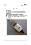
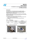
Figure 1.
October 2011
ST-LINK in-circuit debugger/programmer
Doc ID 15285 Rev 5
1/12
www.st.com
Contents
UM0627
Contents
1
2
Overview . . . . . . . . . . . . . . . . . . . . . . . . . . . . . . . . . . . . . . . . . . . . . . . . . . 3
1.1
Features . . . . . . . . . . . . . . . . . . . . . . . . . . . . . . . . . . . . . . . . . . . . . . . . . . . 3
1.2
Product contents . . . . . . . . . . . . . . . . . . . . . . . . . . . . . . . . . . . . . . . . . . . . 3
Hardware layout and configuration . . . . . . . . . . . . . . . . . . . . . . . . . . . . . 4
2.1
3
Connection with STM8 applications . . . . . . . . . . . . . . . . . . . . . . . . . . . . . . 4
2.1.1
SWIM flat ribbon . . . . . . . . . . . . . . . . . . . . . . . . . . . . . . . . . . . . . . . . . . . 5
2.1.2
SWIM separate-wires cable . . . . . . . . . . . . . . . . . . . . . . . . . . . . . . . . . . . 6
2.2
Connection with STM32 applications . . . . . . . . . . . . . . . . . . . . . . . . . . . . . 8
2.3
ST-LINK status . . . . . . . . . . . . . . . . . . . . . . . . . . . . . . . . . . . . . . . . . . . . . . 9
Software configuration . . . . . . . . . . . . . . . . . . . . . . . . . . . . . . . . . . . . . . 10
3.1
USB driver on Windows XP . . . . . . . . . . . . . . . . . . . . . . . . . . . . . . . . . . . 10
3.2
For STM8 application development . . . . . . . . . . . . . . . . . . . . . . . . . . . . . 10
3.3
For STM32 application development and Flash programming . . . . . . . . . 10
Revision history . . . . . . . . . . . . . . . . . . . . . . . . . . . . . . . . . . . . . . . . . . . . . . . . . . . . 11
2/12
Doc ID 15285 Rev 5
UM0627
Overview
1
Overview
1.1
Features
●
5 V power supplied by USB connector.
●
USB 2.0 full speed interface compatible.
●
USB standard A to Mini-B cable provided.
●
SWIM specific features:
●
1.2
–
1.65 V to 5.5 V application voltage supported on SWIM interface.
–
SWIM low speed and high speed modes supported.
–
SWIM programming speed rate:
9.7 Kbytes/s in low speed,
12.8 Kbytes/s in high speed.
–
SWIM cable for connection to an application with an ERNI standard connector
vertical (ref: 284697 or 214017) or horizontal (ref: 214012).
–
SWIM cable for connection to an application with pin headers or 2.54 mm pitch
connector.
JTAG/SWD specific features:
–
3 V to 3.6 V application voltage supported on JTAG/SWD interface and 5 V
tolerant inputs.
–
JTAG/SWD cable provided for connection to a standard JTAG 20-pin pitch
2.54 mm connector.
●
Direct firmware update feature supported (DFU).
●
Status LED which blinks during communication with PC.
●
Operating temperature 0 to 50 °C.
Product contents
Figure 2 shows the ST-LINK and the various cables delivered with the product.
Figure 2.
ST-LINK product contents
SWIM flat ribbon with standard ERNI connector
SWIM separate-wires cable
ST-LINK debugging and programming
JTAG/SWD flat ribbon
Doc ID 15285 Rev 5
USB type A to Mini-B cable
3/12
Hardware layout and configuration
2
UM0627
Hardware layout and configuration
The ST-LINK is designed around the STM32F103C8 (ARM Cortex M3 controller in a
TQFP48 package).
As illustrated in Figure 3 the same connector is used for a SWIM, JTAG or SWD interface
according to the cable connected to it.
Figure 3.
ST-LINK layout
SWIM, JTAG and SWD
target connector
Communication activity LED
USB Mini-B cable input
2.1
Connection with STM8 applications
For STM8 development the ST-LINK can be connected to the target board by two different
cables depending on the connector available on your application board.
The target application voltage (VCC) must be in the range 1.63 V to 5.5 V maximum
Warning:
4/12
Voltages higher than 5.5 V may damage components on the
board.
Doc ID 15285 Rev 5
UM0627
2.1.1
Hardware layout and configuration
SWIM flat ribbon
Figure 4 shows you how to connect the ST-LINK if a standard 4-pin SWIM connector is
present on your application board. The references of the connectors manufactured by ERNI
which must be used on your application board are 284697, 214017 (vertical) or 214012
(horizontal).
Figure 5 shows that pin 16 is missing on the ST-LINK target connector. This missing pin is
used as a safety key on the cable connector to guarantee connection of the SWIM cable in
the correct position on the target connector even pins, used for both SWIM and JTAG/SWD
cables.
Figure 6 shows a SWIM debugging connector layout on flat ribbon.
Figure 4.
ST-LINK connection to target using a standard SWIM connector
Target application board
with ERNI connector ref:
284697, 214017 or 214012
4 wire flat ribbon
with ERNI connector
9-pin plus
Key female connector on
9 pin column of
ST-LINK target connector
Figure 5.
Key detail on connectors
Safety key on SWIM connectors
Safety key on ST-LINK target connector pin 16
SWIM connector plugged on ST-LINK target even pins
Doc ID 15285 Rev 5
5/12
Hardware layout and configuration
.
Table 1.
UM0627
SWIM flat ribbon connections
Pin N°
Name
Function
Target connection
1
TVCC
Target VCC
MCU VCC
2
SWIM
SWIM
MCU SWIM pin
3
GND
GROUND
GND
4
SWIM-RST
RESET
MCU RESET pin
Figure 6.
SWIM debugging connector layout on flat ribbon
1
2
3
4
Viewed from above PCB
2.1.2
SWIM separate-wires cable
As the SWIM separate-wires cable has independent connectors for all pins on one side, it is
possible to connect the ST-LINK to an application board without a standard SWIM
connector. On this flat ribbon all signals are referenced by a specific color and a label to
ease the connection on target.
Table 2 summarizes the signals present on this cable and their connection on the target
board.
Table 2.
Color
SWIM separate-wires cable connections
Cable pin name
Red
TVCC
Green
UART-RX
Blue
UART-TX
Yellow
BOOT0
Orange
Function
Target connection
Target VCC
MCU VCC
Unused
Reserved (not connected on target)
SWIM
SWIM
MCU SWIM pin
Black
GND
GROUND
GND
White
SWIM-RST
RESET
MCU RESET pin
TVCC, SWIM, GND and SWIM-RST can be connected to a low cost 2.54 mm pitch
connector or to pin headers available on the target board.
BOOT0, UART-TX and UART-RX are reserved for future developments.
Figure 7 shows an example of connection to a 2.54 mm pitch connector on target. It shows
how pin 16 is missing on the ST-LINK target connector. This missing pin is used as a safety
key on the cable connector to guarantee connection of the SWIM cable in the right position
on the target connector used for both SWIM and JTAG/SWD cables (even pins of the target
connector).
6/12
Doc ID 15285 Rev 5
UM0627
Hardware layout and configuration
Figure 7.
SWIM separate-wires cable connector layout
Target application board with pin header
TVCC, SWIM, GND and SWIM-RST signals
connected to 2.54 mm pitch connector
UART-RX, UART-TX, BOOT0 remain unconnected
9-pin plus key female connector
on 9-pin column of ST-LINK target connector
Figure 8.
SWIM cable connection detail
Key on SWIM connectors
Doc ID 15285 Rev 5
SWIM cable connected on
ST-LINK target connector even pins
7/12
Hardware layout and configuration
2.2
UM0627
Connection with STM32 applications
For STM32 developments the ST-LINK must be connected to the application using the
standard 20-pin female-female JTAG flat ribbon provided.
Table 3 summarizes signals names, functions and target connection signals of this cable.
Table 3.
JTAG cable connections
Pin N°
Name
ST-LINK function
Target connection
1
TVCC
Target VCC
MCU VCC
3
TRST
GROUND
GND
4
UART-RX
Unused
GND or not connected
5
TDI
JTAG TDO, SWO
TDI
6
UART-TX
Unused
GND or not connected
7
TMS
JTAG TMS, SW IO
TMS, SWIO
8
BOOT0
Unused
GND or not connected
9
TCK
JTAG TCK, SW CLK
TCK, SWCLK
10
SWIM
Unused
GND or not connected
11
NC
Not connected
Not connected
12
GND
GROUND
GND
13
TDO
JTAG TDI
TDO
14
SWIM-RST
Unused
GND
15
RESET
RESET
RESET (optional)
16
KEY
No pin
Not connected
17
NC
Not connected
Not connected
18
GND
GROUND
GND
19
VDD
VDD (3.3V)
Not connected
20
GND
GROUND
GND
2
Observe that pin 16 is not present on the ST-LINK target connector in order to ensure
connection of SWIM cables on even columns of this connector only.
8/12
Doc ID 15285 Rev 5
UM0627
Hardware layout and configuration
Figure 9.
JTAG debugging flat ribbon layout
Target application board
20-pin female JTAG/SWD connector
of flat ribbon on target
20-wire JTAG/SWD flat ribbon
20-pin female connector for flat ribbon on ST-LINK
Figure 10. Debugging connector layout on ST-LINK and flat cable
Viewed from above PCB
The pinout of the target male connector is given in Table 3.
2.3
ST-LINK status
The red LED labelled COM on top of the ST-LINK shows the ST-LINK status (whatever the
connection type).
●
When the LED is ON; communication between the PC and ST-LINK has been initialized
in SWIM or JTAG/SWD mode.
●
When the LED is blinking; data is being exchanged between the target and the PC.
●
When the LED is OFF; ST-LINK communication with the target has not been initialized.
Doc ID 15285 Rev 5
9/12
Software configuration
UM0627
3
Software configuration
3.1
USB driver on Windows XP
On Windows XP, ST-LINK requires the WinUSB driver to be installed. If the toolset installed
it automatically, the file winusb.dll is present in the WINSYSDIR directory (typically
C:\Windows\system32).
If the toolset setup did not install it automatically, the driver can be found on www.st.com:
3.2
1.
Connect to www.st.com.
2.
In the search tab, part number field, look for ST-LINK.
3.
Click on the Generic Part Number column’s hyperlink to ST-LINK.
4.
In the Design support tab, SW DRIVERS section, click on the icon to download stlink_usbdriver.zip.
5.
Unzip and run ST-Link_USBdriver.exe.
For STM8 application development
Please refer to:
●
ST Visual Develop (STVD) tool chain
●
ST Visual Programmer (STVP) for programming STM8 Flash microcontrollers
The ST-LINK is listed in the ST toolchain and programmer environment as a target from
STVD 4.1.0 and STVP 3.1.0.
3.3
For STM32 application development and Flash programming
Please refer to Atollic, IAR and Keil documentation and web sites.
ST-LINK is listed in Atollic, IAR and Keil integrated development environment as a
debugging target from Atollic TrueSTUDIO®/STM32 V1.0.0, IAR EWARM 5.30 and Keil
ARM MDK 3.30 and more recent versions.
For more information on the third party tools please visit:
10/12
●
www.atollic.com
●
www.iar.com
●
www.keil.com
Doc ID 15285 Rev 5
UM0627
4
Revision history
Revision history
Table 4.
Document revision history
Date
Revision
Changes
12-Jan-2009
1
Initial release.
19-Jan-2009
2
Incorrect Rev number on cover page. No other modifications.
20-Nov-2009
3
Replaced images to reflect new ST-LINK casing.
Added third party Atollic and SWD support.
Added Section 2.3.
27-Apr-2011
4
Updated Table 3: JTAG cable connections
04-Oct-2011
5
Added Section 3.1
Doc ID 15285 Rev 5
11/12
UM0627
Please Read Carefully:
Information in this document is provided solely in connection with ST products. STMicroelectronics NV and its subsidiaries (“ST”) reserve the
right to make changes, corrections, modifications or improvements, to this document, and the products and services described herein at any
time, without notice.
All ST products are sold pursuant to ST’s terms and conditions of sale.
Purchasers are solely responsible for the choice, selection and use of the ST products and services described herein, and ST assumes no
liability whatsoever relating to the choice, selection or use of the ST products and services described herein.
No license, express or implied, by estoppel or otherwise, to any intellectual property rights is granted under this document. If any part of this
document refers to any third party products or services it shall not be deemed a license grant by ST for the use of such third party products
or services, or any intellectual property contained therein or considered as a warranty covering the use in any manner whatsoever of such
third party products or services or any intellectual property contained therein.
UNLESS OTHERWISE SET FORTH IN ST’S TERMS AND CONDITIONS OF SALE ST DISCLAIMS ANY EXPRESS OR IMPLIED
WARRANTY WITH RESPECT TO THE USE AND/OR SALE OF ST PRODUCTS INCLUDING WITHOUT LIMITATION IMPLIED
WARRANTIES OF MERCHANTABILITY, FITNESS FOR A PARTICULAR PURPOSE (AND THEIR EQUIVALENTS UNDER THE LAWS
OF ANY JURISDICTION), OR INFRINGEMENT OF ANY PATENT, COPYRIGHT OR OTHER INTELLECTUAL PROPERTY RIGHT.
UNLESS EXPRESSLY APPROVED IN WRITING BY TWO AUTHORIZED ST REPRESENTATIVES, ST PRODUCTS ARE NOT
RECOMMENDED, AUTHORIZED OR WARRANTED FOR USE IN MILITARY, AIR CRAFT, SPACE, LIFE SAVING, OR LIFE SUSTAINING
APPLICATIONS, NOR IN PRODUCTS OR SYSTEMS WHERE FAILURE OR MALFUNCTION MAY RESULT IN PERSONAL INJURY,
DEATH, OR SEVERE PROPERTY OR ENVIRONMENTAL DAMAGE. ST PRODUCTS WHICH ARE NOT SPECIFIED AS "AUTOMOTIVE
GRADE" MAY ONLY BE USED IN AUTOMOTIVE APPLICATIONS AT USER’S OWN RISK.
Resale of ST products with provisions different from the statements and/or technical features set forth in this document shall immediately void
any warranty granted by ST for the ST product or service described herein and shall not create or extend in any manner whatsoever, any
liability of ST.
ST and the ST logo are trademarks or registered trademarks of ST in various countries.
Information in this document supersedes and replaces all information previously supplied.
The ST logo is a registered trademark of STMicroelectronics. All other names are the property of their respective owners.
© 2011 STMicroelectronics - All rights reserved
STMicroelectronics group of companies
Australia - Belgium - Brazil - Canada - China - Czech Republic - Finland - France - Germany - Hong Kong - India - Israel - Italy - Japan Malaysia - Malta - Morocco - Philippines - Singapore - Spain - Sweden - Switzerland - United Kingdom - United States of America
www.st.com
12/12
Doc ID 15285 Rev 5