1
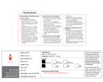
MAX78630+PPM Evaluation Kit User Manual July 2013 Rev. 0 Maxim Integrated cannot assume responsibility for use of any circuitry other than circuitry entirely embodied in a Maxim Integrated product. No circuit patent licenses are implied. Maxim Integrated reserves the right to change the circuitry and specifications without notice at any time. Maxim Integrated 160 Rio Robles, San Jose, CA 95134 USA 1-408-601-1000 © 2013 Maxim Integrated Products, Inc. Maxim Integrated and the Maxim Integrated logo are trademarks of Maxim Integrated Products, Inc. MAX78630+PPM Evaluation Kit User Manual Table of Contents 1 Introduction ......................................................................................................................................... 4 1.1 Ordering Information .................................................................................................................. 4 1.2 Package Contents...................................................................................................................... 4 1.3 System Requirements ............................................................................................................... 4 1.4 Safety and ESD Notes ............................................................................................................... 6 1.5 Testing the MAX78630+PPM EV Board Prior to Shipping ........................................................ 6 2 Installation ........................................................................................................................................... 7 2.1 USB Driver Installation ............................................................................................................... 7 2.1.1 Confirm COM Port Mapping ............................................................................................. 7 2.1.2 FTDI COM Port Trouble Shooting.................................................................................... 7 2.2 Powering the EV Kit Board ........................................................................................................ 8 2.3 Basic Connection Setup ............................................................................................................ 8 2.3.1 Wye-Connected or 3V Delta-Connected Three-Phase Systems..................................... 8 2.3.2 2V Delta-Connected Three-Phase Systems .................................................................. 10 2.3.3 Neutral Current Measurement Considerations .............................................................. 12 2.4 Analog Input Jumper Descriptions ........................................................................................... 13 3 Serial Interfaces Selection and Configuration ............................................................................... 14 3.1 UART Interface Settings .......................................................................................................... 14 3.2 SPI Settings ............................................................................................................................. 15 4 Graphical User Interface (GUI) ......................................................................................................... 17 4.1 GUI Initialization ....................................................................................................................... 17 4.1.1 SSI ID Tab ...................................................................................................................... 17 4.1.2 Device Tab ..................................................................................................................... 18 4.1.3 Scaling Tab .................................................................................................................... 18 4.1.4 Direct Tab....................................................................................................................... 19 4.1.5 Command and Configuration Tab .................................................................................. 20 4.1.6 Calibration Tab ............................................................................................................... 21 4.1.7 Power Tab ...................................................................................................................... 21 4.1.8 Energy Tab..................................................................................................................... 22 4.1.9 Fundamental Tab ........................................................................................................... 22 4.1.10 Min/Max Tab ................................................................................................................. 23 4.1.11 Alarm Tab ..................................................................................................................... 24 4.1.12 Monitor Tab ................................................................................................................... 25 5 Schematics, Bill of Materials, and PCB Layouts............................................................................ 26 5.1 MAX78630+PPM EV Board Schematics ................................................................................. 26 5.2 MAX78630+PPM EV Board Bill of Materials ........................................................................... 28 5.3 MAX78630+PPM EV Board PCB Layouts............................................................................... 30 6 Contact Information .......................................................................................................................... 32 Revision History ........................................................................................................................................ 32 2 Rev 0 MAX78630+PPM Evaluation Kit User Manual Figures Figure 1: MAX78630+PPM EV Kit Typical Application Diagram........................................................................... 5 Figure 2: MAX78630+PPM EV Board Connections .............................................................................................. 8 Figure 3: MAX78630+PPM EV Board Connections ............................................................................................ 10 Figure 4: MAX78630+PPM EV Board Connections ............................................................................................ 12 Figure 5: MAX78630+PPM EV Board Electrical Schematic (1 of 2) ................................................................... 26 Figure 6: MAX78630+PPM EV Board Electrical Schematic (2 of 2) ................................................................... 27 Figure 7: MAX78630+PPM EV Board PCB Top View ........................................................................................ 30 Figure 8: MAX78630+PPM EV Board PCB Bottom View ................................................................................... 31 Table Table 1: J15 Jumper Description......................................................................................................................... 13 Table 2: J11 Jumper Description......................................................................................................................... 13 Table 3: J13 Jumper Description......................................................................................................................... 13 Table 4: J19 Jumper Description......................................................................................................................... 13 Table 5: J42 Jumper Description......................................................................................................................... 13 Table 6: J14 Jumper Description......................................................................................................................... 13 Table 7: J20 Jumper Description......................................................................................................................... 13 Table 8: J43 Jumper Description......................................................................................................................... 13 Table 9: SW4 Serial Interface Selection ............................................................................................................. 14 Table 10: SW5 Address Selection ...................................................................................................................... 14 Table 11: Jumper Setting for UART/USB Interface............................................................................................. 14 Table 12: Jumpers Settings for UART/RS-485/422 ............................................................................................ 15 Table 13: J22 RS-485/422 Connector Pin Assignment ...................................................................................... 15 Table 14: Jumper Setting for SPI/USB Interface................................................................................................. 15 Table 15: Jumper Settings for Connecting on J16 .............................................................................................. 16 Table 16: J16 Connector Pin Assignment ........................................................................................................... 16 Table 17: MAX78630+PPM EV Board Bill of Materials....................................................................................... 28 Rev 0 3 MAX78630+PPM Evaluation Kit User Manual 1 Introduction The MAX78630+PPM Evaluation Kit (EV kit) demonstrates the capability of the MAX78630+PPM for monitoring a three-phase AC load using up to three voltages and three currents (sensors included). The EV kit connects to a PC through a USB cable that provides both power and data communication to the board. A Windows®-based graphical user interface (GUI) communicates with the device over a virtual for simplified access to measurement data and controls. 1.1 Ordering Information PART MAX78630+PPMEVK1# TYPE EV Kit #Denotes a RoHS-compliant device that may include lead that is exempt under the RoHS requirements. 1.2 Package Contents The MAX78630+PPM EV kit includes the following: • • • • • MAX78630+PPM EV Board Three 50A Current Transformers (CR Magnetics CR-8449-2500-N) USB Cable Assembly USB A-B 28/24 1.8M (Tyco/Amp 1487588-3) CD with Documentation, GUI Application, and USB Drivers Calibration Coefficients Document (Hardcopy Only) 1.3 System Requirements In addition to an AC source and load for measuring, the MAX78630+PPM EV kit requires use of a PC with the following features: • • 1GHz processor and 1GB RAM Minimum 1024 x 768 video display resolution • • Available USB port Microsoft Windows 7 or Windows XP® Windows and Windows XP are registered trademarks of Microsoft Corp. 4 Rev 0 MAX78630+PPM Evaluation Kit User Manual Line 3 Line 1 Neutral Line 2 Three Phase AC Source Host PC MAX78630+PPM Eval Board J4 5V Shunt Isolation 3V3 Reg. USB USB Controller RS485 UART Isolation J5 Burden Resistor J 3 9 Burden Resistor J 4 0 Burden Resistor J 4 1 CT1 CT2 CT3 MAX78630 +PPM 16 DIOs Voltage Divider J1 Voltage Divider J2 Voltage Divider J3 Note: Jumpers not shown Three-phase Load Under Test Figure 1: MAX78630+PPM EV Kit Typical Application Diagram Rev 0 5 MAX78630+PPM Evaluation Kit User Manual 1.4 Safety and ESD Notes EXERCISE CAUTION WHEN LIVE AC VOLTAGES ARE PRESENT! Do not connect test equipment, ICE emulators or external development boards directly to the MAX78630+PPM hardware. Damage to the MAX78630+PPM and external equipment will occur due to the MAX78630+PPM’s “high side” reference topology. The MAX78630+PPM’s V3P3 (i.e., “high side”) is connected directly to Neutral (Earth Ground) or Line Voltage, creating a ground reference disparity with any properly grounded external equipment. The board components and firmware settings are designed to operate with the following nominal AC electrical ranges: Voltage Current Line Frequency 10-400V AC 10mA – 50A 46-64Hz The maximum current is determined by the current transformer (CT) that is provided with this EV kit: CR Magnetics model no. CR8449-2500-N. 1.5 Testing the MAX78630+PPM EV Board Prior to Shipping Before every EV kit is shipped, the board (and sensors) undergoes a single-load point calibration using precise energy source equipment. The device temperature is also calibrated at the same time. Results printed out on paper and included with the EV kit. Note that the board is calibrated using the marked CTs included with the kit. Therefore, CT1 should be connected to I1, CT2 to I2, and CT3 to I3. 6 Rev 0 MAX78630+PPM Evaluation Kit User Manual 2 Installation 2.1 USB Driver Installation This EV kit includes an isolated USB interface for serial communications with a PC. The FTDI USB controller IC FT2232 performs the USB functions. The FTDI Windows driver presents a virtual COM port for enabling serial communications. The FTDI Windows driver is a certified driver for Windows XP and Windows 7. Upon attaching the MAX78630+PPM EV board to the PC, the Found New Hardware Wizard automatically launches and installs the appropriate driver files. If your PC does not find the FTDI driver files on its local hard disk drive, locate and reference the FTDI USB Driver and Utilities subdirectory on the CD. The FT2232 controller is powered from the USB cable and is active even when no AC power is applied to the MAX78630+PPM EV kit. Note: If an older FTDI driver has been previously installed, it is recommended to remove the older version before installing this newer FTDI driver. Execute the ftdiClean.exe utility from the FTDI USB Driver and Utilities subdirectory. For FTDI driver support on other operating systems, refer to the FTDI website at www.ftdichip.com. 2.1.1 Confirm COM Port Mapping • Launch the Control Panel and click on the System icon. • The System Properties screen appears. Click on the Hardware tab. Click on Device Manager. Under Ports (COM & LPT), look for the USB Serial Port assignment. • Take note of the COM port assignment for the USB Serial Port. Two sequential COM ports are associated with the kit. Use the second COM port Port numbers may differ on each PC. 2.1.2 FTDI COM Port Trouble Shooting If the FTDI device driver did not install properly, there would be no assigned COM port number for the FTDI controller. Repeat the USB Driver Installation, see Section 2.1. Microsoft Windows may associate a Ball Point device to the FTDI USB controller. When this occurs a FTDI device COM port assignment is available via HyperTerminal but there is no communications data. Verify if a Ball Point device has been added to the “Human Interface Devices” via the Device manager. See Section 2.1.1 for access to the Device Manager. If a Ball Point device exists, delete it and unplug and replug the EV kit’s USB cable. Rev 0 7 MAX78630+PPM Evaluation Kit User Manual 2.2 Powering the EV Kit Board The MAX78630+PPM EV board is normally powered through the USB port (J21).If power needs to be supplied from a different source, a 5V DC can be applied to the connector J16; see Table 16 for the pin assignment. When the MAX78630+PPM EV board is powered through via USB, the same cable also provides the communications link between the host PC and the MAX78630+PPM EV board. 2.3 Basic Connection Setup This section shows examples of basic connections between the MAX78630+PPM EV board and external equipment. Additional connection examples can be seen in the MAX78630+PPM IC data sheet. Note that this board does not directly support voltage transformers (VT) and provides a shunt resistor as alternative to the current transformer on phase C. The following examples are only a subset of all possible measurement configurations. Refer to the MAX78630+PPM IC data sheet for configurations and system connection diagrams. 2.3.1 Wye-Connected or 3V Delta-Connected Three-Phase Systems For Wye-connected systems, all three-phase (Line-to-Neutral) voltages are measured. The Neutral line is the reference for all voltages (V3P3A). Jumper J11 must be in position 2-3 (3V Wye/Delta). It is also possible to directly measure all three voltages in a Delta configuration. In that case, the Neutral is not accessible and the MAX78630+PPM EV board is at a virtual center potential. A B C N V2 V3 J3 V1 J2 J1 Nin J4 J11 Nout I1 J14 J40 I2 J20 J41 CT3 C I3 B LOAD J42 CT2 N J19 CT1 J15 J39 J13 J5 J43 MAX78630EVAL V1 A Neutral Connection for Wye Configurations Figure 2: MAX78630+PPM EV Board Connections 8 Rev 0 MAX78630+PPM Evaluation Kit User Manual 1. 2. 3. 4. 5. 6. 7. 8. 9. Set Jumper J11 to position 2-3. Set Jumper J15 to position1-2. Connect the Neutral from Source to Load and to J4 (Nin) (Wye-connected systems only). Connect the AC source: Phase A to J1, phase B to J2 and Phase C to J3. Connect Phase A current sensor’ secondary side to J39. a. If using a CT, enable burden resistor by closing jumper J13. Also close jumper J14 to disable the 2nd RC circuit. b. If using a Rogowski coil, disable burden resistor by opening jumper J13. Also open jumper J14 to enable the 2nd RC circuit. Connect Phase B current sensor’ secondary side to J40. a. If using a CT, enable burden resistor by closing jumper J19. Also close jumper J20 to disable the 2nd RC circuit. b. If using a Rogowski coil, disable burden resistor by opening jumper J19. Also open jumper J14 to enable the 2nd RC circuit. Connect Phase C current sensor’ secondary side to J41. a. If using a CT, enable burden resistor by closing jumper J42. Also close jumper J43 to disable the 2nd RC circuit b. If using a Rogowski coil, disable burden resistor by opening jumper J42. Also open jumper J14 to enable the 2nd RC circuit Always refer to the IC data sheet for proper connections according to the desired configuration. Write the corresponding value of the CONFIG register to the MAX78630+PPM according to the configuration and the choice of sensors. Note: If a phase is backwards, reverse the current flow through the respective current sensor. Rev 0 9 MAX78630+PPM Evaluation Kit User Manual 2.3.2 2V Delta-Connected Three-Phase Systems For Delta-connected systems, it is possible to measure only two line (Line-to-Line) voltages. For this board, Phase B can be used as reference (V3P3A), therefore measuring VAB and VCB. Jumper J11 must be in position 1-2 (2V Delta). A B C V2 V3 J3 V1 J2 J1 Nin J4 J11 Nout I1 J14 J40 J19 CT1 I2 C I3 B J42 J20 J41 CT3 J15 J39 J13 J5 J43 MAX78630EVAL V1 A LOAD Figure 3: MAX78630+PPM EV Board Connections 10 Rev 0 MAX78630+PPM Evaluation Kit User Manual 1. 2. 3. 4. Set Jumper J11 to position 1-2. Set Jumper J15 to position1-2. Connect the AC source: Phase A to J1, phase B to J2 and Phase C to J3. Connect Phase A current sensor’ secondary side to J39. a. if using a CT, enable burden resistor by closing jumper J13. Also close jumper J14 to disable the 2nd RC circuit. b. if using a Rogowski coil, disable burden resistor by opening jumper J13. Also open jumper J14 to enable the 2nd RC circuit. 5. Connect Phase C current sensor’ secondary side to J41. a. if using a CT, enable burden resistor by closing jumper J42. Also close jumper J43 to disable the 2nd RC circuit. b. if using a Rogowski coil, disable burden resistor by opening jumper J42. Also open jumper J14 to enable the 2nd RC circuit. 6. Always refer to the IC data sheet for proper connections according to the desired configuration. 7. Write the corresponding value of the CONFIG register to the MAX78630+PPM according to the configuration and the choice of sensors. Note: If a phase is backwards, reverse the current flow through the respective current sensor. Rev 0 11 MAX78630+PPM Evaluation Kit User Manual 2.3.3 Neutral Current Measurement Considerations It is possible, in certain Wye configurations to measure the current in the neutral conductor via a shunt resistor, therefore replacing the third phase current measurement. This function is enabled by setting jumper J15 to position 2-3. The MAX78630+PPM EV board then connects the shunt voltage to input AIC of the MAX78630. IC (J41) is not measured in this case. A B C N V2 V3 V1 J1 J2 J3 Nin J4 J11 Nout I1 J14 J40 I2 J20 J41 I3 C B J42 CT2 N J19 CT1 J15 J39 J13 J5 J43 MAX78630EVAL V1 A LOAD Figure 4: MAX78630+PPM EV Board Connections 12 Rev 0 MAX78630+PPM Evaluation Kit User Manual 2.4 Analog Input Jumper Descriptions The following tables describe the various EV board jumpers that determine how analog signals are routed to the inputs of the MAX78630+PPM. Table 1: J15 Jumper Description J15 Pins Description Default 1/2 MAX78630+PPM measures current IC (J41) -Default Installed 2/3 MAX78630+PPM measures shunt current IN (R11) 1/2 Table 2: J11 Jumper Description J11 Pins Description Default 1/2 Measure two voltages (VB is reference) -Default Installed 2/3 Measure three voltages (N is reference) 2/3 Table 3: J13 Jumper Description J13 Pins Description Default 1/2 Insert burden resistor on IA (installed: enable, open: disable) Installed Table 4: J19 Jumper Description J19 Pins Description Default 1/2 Insert burden resistor on IB (installed: enable, open: disable) Installed Table 5: J42 Jumper Description J42 Pins Description Default 1/2 Insert burden resistor on IC (installed: enable, open: disable) Installed Table 6: J14 Jumper Description J14 Pins Description Default 1/2 Enable 2nd RC filter on IA (installed: disable, open: enable) Installed Table 7: J20 Jumper Description J20 Pins Description Default 1/2 Enable 2nd RC filter on IB (installed: disable, open: enable) Installed Table 8: J43 Jumper Description Rev 0 J43 Pins Description Default 1/2 Enable 2nd RC filter on IC (installed: disable, open: enable) Installed 13 MAX78630+PPM Evaluation Kit User Manual 3 Serial Interfaces Selection and Configuration The MAX78630+PPM has integrated UART, SPI (Slave), and I2C (Slave) interfaces. Only one interface can be active at a time and the selection is done at reset/power-on. The UART interface also supports RS-485/422. The MAX78M6630+PPM EV board includes an isolated RS485/422 transceiver. Table 9 shows the settings of SW4 for the individual interface selection; the signal IFC0 and IFC1 are sampled at reset and power-on. Table 9: SW4 Serial Interface Selection Interface Mode SW4 1 (IFC0) SW4 2 (IFC1) SPI 0 (ON) X (don’t care) UART 1 (OFF) 0 (ON) 1 ()FF) 1 (OFF) 2 IC The MAX78630+PPM EV board provides the serial port signals on connector J16. 3.1 UART Interface Settings The MAX78M6630+PPM implements a serial communication protocol (SSI) that supports multipoint communication. The device address (lower bits) is selected through the pins ADDR0 and ADDR1, as shown in Table 10. The upper bits of the address are set through the register DEVADDR, as described in the IC data sheet. Table 10: SW5 Address Selection Device Address SW5 2 Bit 1 DEVADDR[5:1] SW5 1 Bit 0 The EV board includes an isolated RS-485/422 transceiver. The MAX78630+PPM serial UART is connected to the RS-485/422 transceiver when a multi-drop RS-485/422 bus is available. UART/USB Interface and UART/RS-485/422 Interface Configuration In order to operate the UART through the USB/FTDI device or RS-485/422, the jumper must be set according to Table 11. Table 11: Jumper Setting for UART/USB Interface 14 Jumper Position J17 1-2 J18 1-2 J28 Removed J29 Removed J27 Removed J38 Removed J30 Removed J12 Removed Rev 0 MAX78630+PPM Evaluation Kit User Manual UART/RS-485/422 Interface Configuration In order to operate the UART through the RS-485/422 transceiver, the jumpers must be set accordingly to Table 12. Table 13 contains the pin assignment of connector J22. Table 12: Jumpers Settings for UART/RS-485/422 Note: Jumper Position J17 2-3 J18 2-3 J28 Removed J29 Removed J27 (See note) J38 (See note) J30 Removed J12 2-3 These jumpers are used to insert a 120Ω termination on the RS-485 bus. The termination should be inserted or removed according to the board location on the RS-485 bus. Table 13: J22 RS-485/422 Connector Pin Assignment J22 Pin Number Pin Name Pin Description 1 +5V DC Connect to external source 2 Data In – P Three-state, bidirectional 3 Data In – N Three-state, bidirectional 4 Data Out – N Three-state, bidirectional 5 Data Out – P Three-state, bidirectional 6 GND Connect to external source 3.2 SPI Settings The MAX78M6630+PPM has an on-chip SPI (slave) interface. The interface is selected through SW4 according to Table 9. The SPI interface can be accessed through the USB interface or directly via J16; both connectors are galvanically isolated. SPI/USB Interface Configuration Table 14: Jumper Setting for SPI/USB Interface Rev 0 Jumper Position J17 1-2 J18 1-2 J28 Inserted J29 Inserted J27 Removed J38 Removed J30 Inserted J12 1-2 15 MAX78630+PPM Evaluation Kit User Manual SPI/J16 Interface Configuration Table 15: Jumper Settings for Connecting on J16 Jumper Position J17 Removed J18 Removed J28 Removed J29 Removed J27 Removed J38 Removed J30 Inserted J12 1-2 Table 16: J16 Connector Pin Assignment 16 Pin Number Pin Name Pin Description 1 +5V DC Connect to external source 2 SSB SPI Slave Select (SS) 3 MISO Slave Data Out 4 MOSI Slave Data Input 5 SCK Serial Clock 6 GND Ground Rev 0 MAX78630+PPM Evaluation Kit User Manual 4 Graphical User Interface (GUI) A graphical user interface (GUI) is included on the MAX78630+PPM EV kit CD to facilitate quick evaluation of the MAX78630+PPM energy measurement device. The GUI requires Microsoft.NET Framework 4 on the PC for which the GUI is to execute on. Upon invoking the GUI executable file, an installation wizard may appear if Microsoft.NET Framework 4 is not installed on the PC. Follow the installation wizard instructions, or download Microsoft.NET Framework 4 from the Microsoft web site prior to launching the GUI. 4.1 GUI Initialization The GUI is self-explanatory when used with the MAX78630+PPM Data Sheet. The user, however, should note the following about the EV kit hardware: • Serial COM Port: Following the installation instructions in Section 2, launch the GUI executable. Click the Connection pull-down menu and select Connect. 4.1.1 • The COM Port / Baud Rate box appears. Select the COM port assigned to the EV kit and leave the baud rate set to 38400 (default). Click the Connect button. SSI ID Tab SSI ID: Rev 0 Click the SSI tab. Use the SSI ID number set by DIP switch 5 (1 and 2 are closed by default) and click Set Target. Upon successful communication with the EV kit, a message appears in the message box. 17 MAX78630+PPM Evaluation Kit User Manual 4.1.2 Device Tab The Device tab shows to current firmware build as well as the temperature and line frequency being measured. 4.1.3 Scaling Tab The Scaling tab is used to set the scale factors for voltages, currents, and power results. They should be set in accordance to the external circuitry that is being used. The scale factors are then used in the following result tabs to convert numeric results obtained from the MAX78630+PPM device to real world values. The user can also choose to round the results (Power, Energy, Fundamental/Harmonics, Frequency and Temperature) to a specified number of decimal places. 18 Rev 0 MAX78630+PPM Evaluation Kit User Manual 4.1.4 Direct Tab The Direct tab allows access to the all the registers and can both read and write to the registers. The data can be displayed with the scale factor and units applied for convenience. In the example below, the voltage register is being read, so the volts option is used to display the data. Rev 0 19 MAX78630+PPM Evaluation Kit User Manual 4.1.5 Command and Configuration Tab The Command and Config tab controls two frequently used registers: • Get and Set Command Register: These buttons essentially do the same thing as the direct register reads and writes, but specifically for the command register while the Direct tab is for any pother registers that need to be accessed. Hex and decimal formats are supported. • Get and Set Configuration Register: These buttons are used to set up the measurement configurations for the MAX78630+PPM. Refer to the IC data sheet Section 2.19 for details on how this is used. The configuration must be configured before the MAX78630+PPM is used by getting the default configuration and setting it. Once this is done it can be saved to NV RAM for future use, or programmed to a user-defined configuration and saved. See the Calibration tab for saving the settings. 20 Rev 0 MAX78630+PPM Evaluation Kit User Manual 4.1.6 Calibration Tab The Calibration tab is used to calibrate all the measurement channels. The calibration targets can be viewed and changed and the scaling parameters are also displayed for convenience. Use the Calibration Options to select the parameters to be calibrated. The calibration and NV RAM are also saved using the provided button. 4.1.7 Power Tab The Power tab displays the current power being consumed by the loads. P (active power), Q (reactive power), and S (apparent power) are displayed along with the voltage, current, crest factor, and power factor. Rev 0 21 MAX78630+PPM Evaluation Kit User Manual 4.1.8 Energy Tab The Energy tab displays the accumulated power both into and out of the load. All energy counters can be reset to zero in the device with the Reset button. 4.1.9 Fundamental Tab The Fundamental tab is used to display the fundamental and harmonic measurements for voltage, current, and power. The harmonics displayed can be selected with the get/set harmonic buttons. 22 Rev 0 MAX78630+PPM Evaluation Kit User Manual 4.1.10 Min/Max Tab The Min/Max tab is used to display the minimum and maximum measurements for the parameters selected in the Word Addr column. The units can be selected with the provided pull-down menu and the most recent measurements are updated using the get buttons. All the measurements are reset with the reset button. Rev 0 23 MAX78630+PPM Evaluation Kit User Manual 4.1.11 Alarm Tab The Alarm tab is a user-definable display of whatever parameters are required in a particular application. The alarms are described in detail in Sections 2.11 and 2.12 of the MAX78630+PPM IC data sheet. 24 Rev 0 MAX78630+PPM Evaluation Kit User Manual 4.1.12 Monitor Tab The Monitor tab is a running record of all the communications between the GUI and the target MAX78630+PPM. A log file can be generated to save the transactions for later analysis. Rev 0 25 MAX78630+PPM Evaluation Kit User Manual 5 Schematics, Bill of Materials, and PCB Layouts This section includes the schematics, bill of materials, and PCB layouts for the MAX78630+PPM EV board. 5.1 MAX78630+PPM EV Board Schematics . J9 CON1 J8 CON1 J6 CON1 J10 CON1 V3P3 1 R3 10K 0603 V3P3A VC 1 2 3 4 R1 1M, 0.1% C1 0.1uF 0603 R4 750, 0.1% 0603 R2 1M, 0.1% C2 1000pF 0603 DNP LOGO4 1 V3P3A J2 CON4 1 2 3 4 R5 1M, 0.1% R6 1M, 0.1% R7 750, 0.1% 0603 C3 0.1uF 0603 C4 1000pF 0603 1 2 3 4 R8 1M, 0.1% R9 1M, 0.1% R10 750, 0.1% 0603 C5 0.1uF 0603 C6 1000pF 0603 SW1 MAXIM 6610 Reset GND V3P3A J3 CON4 V3P3A 1 2 3 V3P3A J11 CON3 Jumper Pos 1-2: 2V Delta (VB is ref erence) Pos 2-3: 3V Wy e/Delta J7 CON18 SIP100P18 V3P3 R21 0 0603 V3P3A GND C38 0.1uF 0603 C39 0.1uF 0603 GND 24 J5 CON4 1 2 3 4 R11 0.004, 1%, 2.5W R12 750, 0.1% 2512P 0603 C7 0.1uF 0603 C8 1000pF 0603 25 26 27 AV1 AV2 AV3 RESETB DIO0 DIO1 DIO2 DIO3 DIO4 DIO5 DIO6 DIO7 DIO8 DIO9 DIO10 DIO11 DIO12 DIO13 DIO14 DIO15 Jumper J15 Pos 1-2: 3I Pos 2-3: 2I + Shunt on Neutral J15 IA 28 32 R13 4.99, 1% 1210 R14 750, 0.1% 0603 C9 0.1uF 0603 C10 0.047uF 0603 RES1 RES2 C11 1000pF 0603 V3P3A 1 2 IB J40 Block2 5.08 mm/2 1 2 J20 CON2 SIP100P2 XIN XOUT 23 GND 20 18 17 16 9 8 6 4 3 22 21 19 10 7 5 2 AL1 SPCK/ADDR0 SDI/RX/SDAI SDO/TX/SDAO AL2 SSB/DIR/SCL AL3/ADDR1 AL4 IFC0 IFC1 AL5 SGNV1 SGNV2 SGNV3 SPCK SCK SDI MOSI SDO MISO SSB 12 13 J19 CON2 SIP100P2 R16 4.99, 1% 1210 1 Y1 2 R38 10K 0603 20.00MHz GND C12 0.1uF 0603 SW5 SW DIP-2 C13 0.047uF 0603 C14 1000pF 0603 R19 4.99, 1% 1210 J42 CON2 SIP100P2 R33 10K 0603 method used. SW4 can be set to SW4 SW DIP-2 1s after power-up to free up the GPIO lines I2C Address Bits SW2 determines ADDR0 and ADDR1 COMMUNICATIONS MODE R79 1K 1 1 1 IC 1 2 R39 10K 0603 The state of SW4 at power-up determines the communications R18 750, 0.1% 0603 R78 1K R80 1K R77 1K Test points Currents J43 CON2 SIP100P2 Optional RC f or Rogowski Coils (Close Jumper f or CT) CON1 J44 CON1 J45 CON1 J46 R20 750, 0.1% 0603 SPI 0x UART 10 I2C 11 GND 1 2 Insert Burden Resistor (Close Jumper f or CT) J41 Block2 5.08 mm/2 R36 10K 0603 GND V3P3A 1 2 V3P3 C19 18pF 0603 C18 18pF 0603 Optional RC f or Rogowski Coils (Close Jumper f or CT) R17 750, 0.1% 0603 SSB V3P3 U1 MAX78630-32 QFN32L GND V3P3 1 2 Insert Burden Resistor (Close Jumper f or CT) GNDD GNDD 1 2 V3P3A CON3 R15 750, 0.1% 0603 GNDA J39 Block2 5.08 mm/2 J13 CON2 SIP100P2 1 1 2 AI1 AI2 AI3 14 15 Insert Burden Resistor (Close Jumper f or CT) 1 2 CT secondary inputs 29 30 31 3 2 1 J14 CON2 SIP100P2 Optional RC f or Rogowski Coils (Close Jumper f or CT) C40 0.1uF 0603 11 GND V3P3D Nout 1 2 3 4 V3P3A Nin J4 CON4 DIO connector 18 17 16 15 14 13 12 11 10 9 8 7 6 5 4 3 2 1 VB J1 CON4 Warning DIO15 DIO14 SGNV3/DIO13 SGNV2/DIO12 SGNV1/DIO11 AL5/DIO10 IFC1/DIO9 IFC0/DIO8 AL4/DIO7 AL3/ADDR0/DIO6 SSB/DIR/SCL/IFC1/DIO5 AL2/DIO4 SDO/TX/SDAO/DIO3 SDI/RX/SDAI/DIO2 SPCK/ADDR0/DIO1 AL1/DIO0 VA DNP LOGO1 1 1 1 1 Test points Voltages Voltage inputs R22 750, 0.1% 0603 C15 0.1uF 0603 C16 0.047uF 0603 C17 1000pF 0603 V3P3A MT1 MT2 MT3 MT4 PCB Peg PCB Peg PCB Peg PCB Peg Maxim - Teridian Smart Grid Solutions Title MAX78630TQFN32EVALV1 Size B Document Number MAX78630 TQFN32 Ev aluation Board Date: Friday , April 12, 2013 Rev 1 Sheet 1 of 2 Figure 5: MAX78630+PPM EV Board Electrical Schematic (1 of 2) 26 Rev 0 MAX78630+PPM Evaluation Kit User Manual . R40 0 0603 5VUSB Isolation AVCC GND R45 0 0603 R57 1K 0603 U7 1 2 VDD1VDD2 3 GND1GND2 4 IN1 OUT1 5 IN2 OUT2 6 OUT3 IN3 7 OUT4 IN4 NC 8 NC GND GND1GND2 IL516-3E R56 1K 0603 SCKout V3P3 SCK SPCK SPCK V3P3 8 7 6 5 SSB/TXEN SSB SSB C31 MISOF MISOout 1 2 3 40 39 38 37 36 35 33 32 30 29 28 27 26 MOSIF MOSIin SCKin R49 0 0603 U8 Vdd2 Vdd1 Voe IN OUT SY NC GND2 GND1 1 2 3 4 SSBin 1 2 3 IL510-3E J18 CON3 SSBout GND 1 2 3 RS485TXEN BD0 BD1 BD2 BD3 BD4 BD5 BD6 BD7 BC0 BC1 BC2 BC3 SI/WUB U3 FT2232C TQFP48 RS485/USB Select 0603 0.1uF J12 CON3 RS485 TXen/ SSB Select 16 15 14 13 12 11 10 9 2 1 J30 SSBF 2 1 GND MISOin SIP100P2 CON2 J29 46 VCC2 VCC1 AVCC PWREN 3V3OUT RESETB USBDM USBDP RSTOUTB C25 0.033uF 0603 41 6 USB3 J21 USB 4 R46 500 ma Max 2.2K 0603 8 7 USBDM USBDP 5 RSTOB XTI XTIN XTOUT 43 44 R50 1M 0603 TEST USB SPI & UART 2 Y2 6MHz XTO EESK EECS EEDATA C27 10uF 0805 R47 2.2K 0603 1 2 3 4 5 6 1 C28 0.1uF 0603 SDO SDI MISO SDO MOSI SDI R58 1K 0603 AD0 AD1 AD2 AD3 AD4 AD5 AD6 AD7 AC0 AC1 AC2 AC3 S1/WUA AGND 5VIN C26 0.1uF 0603 24 23 22 21 20 19 17 16 15 13 12 11 10 1 48 2 47 R53 10K 0603 45 RXFTDI V3P3 C24 0.1uF 0603 C23 0.1uF 0603 31 14 SIP100P2 J28 CON2 42 3 1 R43 10K 0603 VCCIOB VCCIOA GND 5VIN C21 10uF 0805 GND4 GND3 GND2 GND1 GND R41 470 0603 34 25 18 9 VGND R42 10K 0603 2 1 C20 10uF VIN VOUT NC4 NC3 NC2 NC1 TX/RX wireOR Select 4 2 8 7 6 3 +5VISO 5 C22 0.1uF 0603 5VIN VR2 VBT1-5V +5VISO J16 CON6 SIP100P6 3 6 5 4 3 2 1 Optional External I2C or SPI J17 CON3 RS485/USB Select R54 10K 0603 GND R59 120 0805 2 1 5VIN C29 0.1uF 0603 RS485RX RS485TXENout VR3 3.3V @ 950mA V3P3 LD1117S33CTR C53 1000pF 0603 C54 0.1uF 0603 GND VOUT GND C52 10uF 0805 TAB 1 4 2 VIN SOT223 RS485TXENout U11 1 2 3 4 5 6 7 VL RO DE RE DI GND NC VCC NC A B Z Y GND MAX13433EESD+ 3 +5VISO C55 0.1uF 0603 GND +5VISO 14 13 12 11 10 9 8 R52 120 0805 2 1 C30 1uF 0603 J38 CON2 SIP100P2 5VIN RS485A RS485B RS485Z RS485Y J27 CON2 SIP100P2 1 2 3 4 5 6 J22 Block6 RS485 Do NOT apply +5VDC to J22-1 when USB cable is attached to J21. GND Maxim - Teridian Smart Grid Solutions Title MAX78630TQFN32EVALV1 Size B Document Number MAX78630 TQFN32 Dev elopment Board Date: Friday , April 12, 2013 Sheet Rev 1 2 of 2 Figure 6: MAX78630+PPM EV Board Electrical Schematic (2 of 2) Rev 0 27 MAX78630+PPM Evaluation Kit User Manual 5.2 MAX78630+PPM EV Board Bill of Materials Table 17: MAX78630+PPM EV Board Bill of Materials Item Quantity Reference C1,C3,C5,C7,C9,C12,C15,C22,C23,C24, 1 19 C26,C28,C29,C31,C38,C39,C40,C54,C55 2 8 C2,C4,C6,C8,C11,C14,C17,C53 3 3 C10,C13,C16 4 2 C18,C19 5 4 C20,C21,C27,C52 6 1 C25 7 1 C30 8 5 J1,J2,J3,J4,J5 9 7 J6,J8,J9,J10,J44,J45,J46 10 1 J7 11 5 J11,J12,J15,J17,J18 12 11 J13,J14,J19,J20,J27,J28,J29,J30,J38,J42,J43 13 1 J16 14 1 J21 15 1 J22 16 3 J39,J40,J41 17 4 MT1,MT2,MT3,MT4 18 6 R1,R2,R5,R6,R8,R9 19 9 R3,R33,R36,R38,R39,R42,R43,R53,R54 20 10 R4,R7,R10,R12,R14,R15,R17,R18,R20,R22 21 1 R11 22 3 R13,R16,R19 28 Part PCB Footprint 0.1uF 1000pF 0.047uF 18pF 10uF 0.033uF 1uF CON4 CON1 CON18 CON3 CON2 CON6 USB Block6 Block2 PCB Peg 1M, 0.1% 10K 750, 0.1% 0.004, 1%, 2.5W 4.99, 1% 603 603 603 603 805 603 603 STERM SIP100P1 SIP100P18 SIP100P3 SIP100P2 SIP100P6 USBB TERM BLK 200-6 5.08 mm/2 MTGPS.PRT 1206W 603 603 2512P 1210 Rev 0 MAX78630+PPM Evaluation Kit User Manual Table 17 continued Item Quantity Reference 23 4 R21,R40,R45,R49 24 1 R41 25 2 R46,R47 26 1 R50 27 2 R52,R59 28 7 R56,R57,R58,R77,R78,R79,R80 29 1 SW1 30 2 SW4,SW5 31 1 U1 32 1 U3 33 1 U7 34 1 U8 35 1 U11 36 1 VR2 37 1 VR3 38 1 Y1 39 1 Y2 Rev 0 Part 0 470 2.2K 1M 120 1K PUSHBUTTON SW DIP-2 MAX78630-32 FT2232C IL516-3E IL510-3E MAX13433EESD+ VBT1-5V 3.3V @ 950mA 20.00MHz 6MHz PCB Footprint 603 603 603 603 805 603 EP11 DIP4 QFN32L TQFP48 SO-16 NARROW IL611A SO-14 NARROW VBT1 SOT223 ABLS CSTCR 29 MAX78630+PPM Evaluation Kit User Manual 5.3 MAX78630+PPM EV Board PCB Layouts Figure 7: MAX78630+PPM EV Board PCB Top View 30 Rev 0 MAX78630+PPM Evaluation Kit User Manual Figure 8: MAX78630+PPM EV Board PCB Bottom View Rev 0 31 MAX78630+PPM Evaluation Kit User Manual 6 Contact Information For more information about Maxim products or to check the availability of the MAX78630+PPM, contact technical support at www.maximintegrated.com/support. Revision History REVISION NUMBER REVISION DATE 0 7/13 32 DESCRIPTION Initial release PAGES CHANGED — Rev 0