1
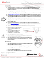
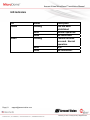
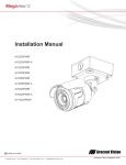
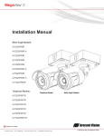
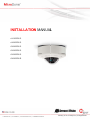
INST TALL LATIO ON MA ANUAL L AV1455DN-S AV2455DN-S AV2456DN-S AV3455DN-S AV3456DN-S AV5455DN-S Arecont Vision MicroDome™ Installation Manual MicroDome™ Surface Mount Installation Contents Package Contents ....................................................................................................................................................... 3 Warranty Information ................................................................................................................................................ 3 Installation Overview ................................................................................................................................................. 4 Installation ................................................................................................................................................................. 5 Focusing the Camera .................................................................................................................................................. 6 Changing the Lens ...................................................................................................................................................... 7 Focusing Alternate Lenses ......................................................................................................................................... 7 Digital Input and Output ............................................................................................................................................ 8 LED Indicators ............................................................................................................................................................ 9 Support .................................................................................................................................................................... 10 Camera Discovery, Setup, and Configuration .......................................................................................................... 11 Wall Mount Accessory ............................................................................................................................................. 12 Pendant Mount Accessory ....................................................................................................................................... 13 Mount Template: MicroDome Camera .................................................................................................................... 14 Mount Template: MicroDome Wall Mount ............................................................................................................. 15 Mount Template: MicroDome Pendant Mount ....................................................................................................... 16 Page | 2 [email protected] Arecont Vision MicroDome™ Installation Manual Package Contents Item MegaPixel Camera Mounting Kit Arecont Vision CD Description MicroDome™ Ceiling template 6x Mounting Screws (#6x1” for wood or sheet metal) 6x Mounting Anchors 3/8” NPT Male to 1/2” NPT Female Adapter Network Patch Cable 3x Security Torx Dome Cover Fasteners Manual, Warranty, Installation Software Warranty Information 3 Year Limited Warranty ARECONT VISION warrants to Purchaser (and only Purchaser) (the “Limited Warranty”), that: (a) each Product shall be free from material defects in material and workmanship for a period of thirty-six (36) months from the date of shipment (the “Warranty Period”); (b) during the Warranty Period, the Products will materially conform with the specification in the applicable documentation; (c) all licensed programs accompanying the Product (the “Licensed Programs”) will materially conform with applicable specifications. Notwithstanding the preceding provisions, ARECONT VISION shall have no obligation or responsibility with respect to any Product that (i) has been modified or altered without ARECONT VISION’s written authorization; (ii) has not been used in accordance with applicable documentation; (iii) has been subjected to unusual stress, neglect, misuse, abuse, improper storage, testing or connection; or unauthorized repair; or (iv) is no longer covered under the Warranty Period. ARECONT VISION MAKE NO WARRANTIES OR CONDITIONS, EXPRESS, IMPLIED, STATUTORY OR OTHERWISE, OTHER THAN THE EXPRESS LIMITED WARRANTIES MADE BY ARECONT VISION ABOVE, AND ARECONT VISION HEREBY SPECIFICALLY DISCLAIMS ALL OTHER EXPRESS, STATUTORY AND IMPLIED WARRANTIES AND CONDITIONS, INCLUDING THE IMPLIED WARRANTIES OF MERCHANTABILITY, FITNESS FOR A PARTICULAR PURPOSE, NON-INFRINGEMENT AND THE IMPLIED CONDITION OF SATISFACTORY QUALITY. ALL LICENSED PROGRAMS ARE LICENSED ON AN “AS IS” BASIS WITHOUT WARRANTY. ARECONT VISION DOES NOT WARRANT THAT (I) THE OPERATION OF THE PRODUCTS OR PARTS WILL BE UNINTERRUPTED OR ERROR FREE; (II) THE PRODUCTS OR PARTS AND DOCUMENTATION WILL MEET THE END USERS’ REQUIREMENTS; (III) THE PRODUCTS OR PARTS WILL OPERATE IN COMBINATIONS AND CONFIGURATIONS SELECTED BY THE END USER; OTHER THAN COMBINATIONS AND CONFIGURATIONS WITH PARTS OR OTHER PRODUCTS AUTHORIZED BY ARECONT VISION OR (IV) THAT ALL LICENSED PROGRAM ERRORS WILL BE CORRECTED. For RMA and Advance Replacement information visit ArecontVision.com Page | 3 [email protected] Arecont Vision MicroDome™ Installation Manual Installation Overview Ceiling Gasket NPT Port Camera Housing Mounting Screws Captive Fasteners (Hand Tighten Only) Page | 4 [email protected] Gasket Dome Cover Arecontt Vision MicroDome™ ™ Installation Manual Installation Tech Tip 1. Wiring method W ds shall be in accordance w with the Natioonal Electricaal Code/NFPA A 70/ANSI, and d with all lo ocal codes and d authorities having jurisd diction. Wiringg should be U UL Listed and//or Recognizeed wire su uitable for the e application. 2. Operating Tem O mperature ‐40 0°C (‐40°F) to +50°C (122°FF) 3. Always use hardware e.g. screws, ancho ors, bolts, lockking nuts etc. which are co ompatible witth mounting urface and off sufficient len ngth and consstruction to innsure a securre mount su 4. Visit http://ww ww.arecontvision.com/ and check to ennsure your caamera has thee most curren nt firmware. or installation ns in harsh en nvironments iit is recommeended to use all six mountting screws su upplied with 5. Fo yo our camera to o create the b best seal posssible betweenn your camerra and the mo ounting surfacce using the su upplied gaske et. 6. If using the NP PT port alwayss use Teflon ttape around tthreads to en nsure proper ssealing. 7. After plugging in the netwo ork cable checck that the inddicator LED’ss are indicatin ng the desired d conditions (ssee LED Indicaator table). 8. Use Arecont Vision softwarre AV100 or A AV200 locatedd on the CD o or available fo or download aat our website (www w w.arecontvisio on.com) for caamera discoveery and setup p (see Instrucction Manual located on CD or available e on our website). n and tilt to ob btain the desired field of vview (see Focusing Instructtions). 9. Adjust the pan 10. Le ens may be fu urther secure ed by tightening th he lens lock sccrew using Ph hillips head sccrewdriver. 11. In nstall the Dom me Cover by aaligning the caaptive fastene ers with the m mating th hreaded holes on the came era housing. 12. When mountin W ng the Dome Cover to the Camera Housing ensurre that the gasket is properly seating annd not folded. Failure to do so may resu ult in water and dust ingre ess. W ng the Dome Cover to the Camera Hou sing do not o over torque 13. When mountin th he three captive fasteners as this will caause the threeads to strip. Only hand tighten these sscrews. Best Practtice Tips When mountin W ng to vertical surface it is b best to use thhe Wall Moun nt Accessory (M MCD‐WMT) w which includes a junction b box. Fo or outdoor usse it is alwayss best to prop perly seal the product usin ng caulk arround the edges to preven nt water ingre ess from mouunting to poro ous or uneven surface es. Use Teflon tap pe on threade ed interfaces. Use all 6 supplied mountingg screws for b best seal wheen mounting o outdoors. Page | 5 [email protected] Arecontt Vision MicroDome™ ™ Installation Manual Focusing the C Camera 1. Open a live vie O ew of the cam mera from you ur web browsser or the AV Software pro ovided (AV100 0 or AV200). 2. Lo oosen the len ns lock screw using a phillip ps head screw wdriver (if necessary). Only do so if len ns seems very y tight when turrning. Lock sccrew should enough to pro ovide some be tightened e frriction againstt the lens to aavoid fo ocusing problems. 3. Manually rotat M te the lens to o adjust the fo ocus until the desired imagge is obtained. or some lense es a focus shift will occur o once the bub ble is in placee. Hold the bubble up to tthe lens when n 4. Fo fo ocusing to acccount for the focus shift orr see the “Foccusing Alternate Lenses” ssection below w for further in nstruction. 5. Retighten the lock screw if necessary. 6. In nstall the Dom me Cover by aaligning the caaptive fasten ers with the m mating threaded holes on the camera housing. W ng the Dome Cover to the Camera Hou sing ensure that the gaskeet is properly seating and 7. When mountin not folded. Faailure to do so o may result in water and ddust ngress. in 8. When mountin W ng the Dome Cover to the Camera Hou sing do not over torqu ue the three ccaptive fasten ners as this w ill cause he threads to strip. Only h hand tighten tthese screws.. th Tech Tip Tech Tip Page | 6 [email protected] Arecontt Vision MicroDome™ ™ Installation Manual Changging the Lens 1. Remove the Dome Cover byy loosening th he captive fassteners. 2. Lo oosen the len ns lock screw using a phillip ps head screw wdriver (if necessary). Only do so if len ns seems very y tight when turrning. 3. Manually unsc M crew the lens,, this may takke se everal second ds. 4. Replace lens. 5. Retighten the lock screw if necessary. 6. Reinstall Dome e Cover per in nstructions outlined above e. Focusing Alternate Le enses When foccusing the 6m mm, 8mm, 12m mm or 16mm m lens optionss you will enco us shift when using the ounter a focu bubble. TTo account for this follow tthese steps: 1. 2. 3. 4. Tech Tip Fo ocus the camera without tthe bubble. Rotate the lens per the chart below. The e rotation wi ll account forr most of the focus shift. h bubble on. YYou should be close to beiing focused. Put cover with Remove cover and rotate a couple degre ees at a time in either direection until yo ou gain the deesired image.. Lens MPM16.0 MPM12.0 MP PM8.0 MP PM6.0 16mm 12mm 8mm 6mm Rotattion <3/4 CCW W 1/4 CCW >1/8 CCW W 1/8 CCW 250° 90° 60° 45° Example: Using a 16mm m lens you will focus the le ens without tthe bubble un ntil you get th he desired im mage. Rotate the lens aalmost ¾ of a turn (250°). Put the bubb ble on and vieew the image.. It should bee almost in focus. Remove e the bubble and rotate a degree or ttwo in one dirrection and v iew the imagge with the bu ubble on. Depending on e you may nee ed to adjust in the oppositte direction oor continue in n the same dirrection until tthe desired the image image is o obtained. Page | 7 [email protected] Arecont Vision MicroDome™ Installation Manual Digital Input and Output Use 4 position connector inside camera housing to interface with Digital I/O. DIGITAL I/O BLACK IN ‐ WHITE IN + YELLOW OUT ‐ ORANGE OUT + Electrical Characteristics Input Voltage (V) (Measured between + and – terminals) Output Current (mA) (Measured between + and – terminals) Applied Voltage Range : 0‐80V MIN MAX ON 2.9 6.3 OFF 0 1.3 ON ‐ 50 OFF ‐ 0.1 NOTE: Both the input and the output are electrically isolated from the rest of the camera’s electrical circuitry via general‐purpose photo couplers. The input is additionally protected with a serial 250 Ohm resistor and a debouncing circuit. Duration of any input signal should be at least 5ms to comply with the requirements of the debouncing circuit. Page | 8 [email protected] Arecont Vision MicroDome™ Installation Manual LED Indicators LED Yellow Status Flashing Green Solid None Flashing Solid None Page | 9 [email protected] Description Link has been established. Normal Operation. No connection. Camera has been accessed. Normal operation. N/A No Connection. Arecont Vision MicroDome™ Installation Manual Support 1. Arecont Vision FAQ Page Located at ArecontVision.com 2. Check the following before you call: Restore camera to factory default with AV100, AV200 or the camera webpage. Upgrade to the latest firmware by visiting ArecontVision.com. Isolate the camera on a dedicated network and test with AV100 or AV200. Swap the “troubled” camera with a known good camera to see if the problem follows the camera or stays at the location. 3. Contact Arecont Vision Technical Support one of three ways: 1. Online Portal : Support.ArecontVision.com 2. Phone : 1.818.937.0700 (option #1) 3. Email : [email protected] Page | 10 [email protected] Arecont Vision MicroDome™ Installation Manual Camera Discovery, Setup, and Configuration For camera discovery and setup please use Arecont Vision software AV200 which you can find on the CD included with your camera or at: http://www.arecontvision.com/softwares.php The user manual for the AV200 software is included on the CD and is also located on our website. To configure the camera use either the AV200 software or the web interface utility. The web interface can be accessed by typing the camera IP address into your web browser or by clicking on the web interface button in AV200. The user manual for our web interface is included on the CD and is also located on our website. Page | 11 [email protected] Arecontt Vision MicroDome™ ™ Installation Manual Wall M Mount A Accessorry (MCD‐‐WMT) Gaskeet Allignment features must be aliggned for prroper instaallation. Installattion Notes: 1. 4x mountin 4 ng screws aare #10x1” wood or ssheet metaal screws (4x mount anchors also include ed). 2. Always ens ure gasketts are prop A perly seatedd. 3. Use Teflon U tape on th hreaded intterfaces. 4. 3/8” male tto 1/2” fem male NPT adapter inccluded. 5. Mount hole M es from cam mera houssing to flannge are nott symmetrical. Alignment fe eatures ind dicated mu ust be prop perly lined up for mo ount hole aalignment. Page | 12 suppo ort@arecontv vision.com Arecontt Vision MicroDome™ ™ Installation Manual Pendaant Mou unt Accessory (M MCD‐CM MT) Installation Notes: 1. 3x mountting screwss are #10x1” wood or ssheet metaal screws ((3x mount an nchors also o included)). nsure gaskkets are pro operly 2. Always en seated. on tape on threaded 3. Use Teflo interfacess. 4. 3/8” malee to 1/2” feemale NPTT adapter in ncluded. 5. Mount hooles from ccamera housing to flange are not syymmetricall. Alignmen nt features indicated must be properly lined up p for moun nt hole align nment. Gaasket Alignmentt features must be aligned for proper insstallation. Page | 13 suppo ort@arecontv vision.com Arecont Vision MicroDome™ Installation Manual Mount Template: MicroDome Camera Page | 14 [email protected] Arecont Vision MicroDome™ Installation Manual Mount Template: MicroDome Wall Mount Page | 15 [email protected] Arecont Vision MicroDome™ Installation Manual Mount Template: MicroDome Pendant Mount Page | 16 [email protected] Arecont Vision MicroDome™ Installation Manual Contact Arecont Vision Technical Support one of three ways: Online Portal : Support.ArecontVision.com Phone : 1.818.937.0700 (option #1) Email : [email protected] Page | 17 [email protected]