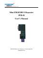
1
http://www.FOURSTAR-dy.com
Mini PROFIBUS Repeater
PFB-R
User's Manual
FOURSTAR Electronic Technology Co., Ltd. Deyang China
All Right Reserved
User Manual for Mini PROFIBUS Repeater
Contents
Preface ………………………………………………………………………………………………………3
Copyright Statement …………………………………………………………………………………….......3
Version Information …………………………………………………………………………………………3
Packaging List…………………………………………………………………………………………..……4
I. Basic Features of PROFIBUS Network ……………………..…………………………………….…..….4
II. Main Applications and Features of Mini PROFIBUS Repeater …………………..……………….…… 6
III. Features and Specifications …………………………………………………………..…………....……7
IV. External Structure and Pin Definition………………………………………………..……………….…8
V. Internal Functional Block Diagram………………………………………………………..……..…..…10
VI. Major Application Scheme of Mini PROFIBUS Repeater ……….……………………….. …………11
VII. FAQ……………………………………………………………………………………………...……12
VIII. Ordering Information …......…......…......…......….................…......…..…......…......….....…..…......15
_________________________________________________________________________________________________
-2Deyang FOURSTAR Electronic Technology Co., Ltd.
TEL:+86-838-2515543
FAX:+86-838-2515546
http://www.FOURSTAR-dy.com
User Manual for Mini PROFIBUS Repeater
Preface
Thank you for using Fieldbus Network Products released by FOURSTAR Electronic Technology Co.,
Ltd. Deyang China.
Before use, be sure to carefully read the user's manual, where you will find brief usage methods and
interesting functions of this product.
The user's manual gives detailed instruction about how to use Mini PROFIBUS Repeater, PFB-R.
Another product of similar outline released before is PROFIBUS Isolator whose model number is PFB-G.
The product is mainly used in Fieldbus Network, like PROFIBUS, MPI, PPI, etc. It isolates, repeats,
and amplifies Signal RS485, in order to prolong the communication distance and increase the number of
stations, or change the topological structure of PROFIBUS/MPI/PPI Network. Such device can start
working after connecting to DP socket. It can be installed easily and covers little space. It aims to bring
convenience to the field's wiring installation, prolong the network's transmission distance, and uplift and
quantity of stations. Meanwhile, it can isolate network and diagnose signal indication.
Please do follow the technical and functional specifications in the manual. The company does not
assume the property loss or personal injury caused by user's improper handling.
The company has the right to modify the manual's contents and product functions before
announcement if the technical development requires.
Copyright Statement
The manual's copyright belongs to FOURSTAR Electronic Technology Co., Ltd. Deyang China. Any
individual or organization copied the manual's contents in full or in part without the company's consent in
writing will assume the corresponding liability.
Version Information
Document Name: A User's Manual for Mini PROFIBUS Repeater
Version: V3.8
_________________________________________________________________________________________________
-3Deyang FOURSTAR Electronic Technology Co., Ltd.
TEL:+86-838-2515543
FAX:+86-838-2515546
http://www.FOURSTAR-dy.com
User Manual for Mini PROFIBUS Repeater
Modification Date: May, 13th, 2011
Packaging List
1. A PFB-R
2. A CD-ROM (include user's manual, etc. No software or driver is needed for the product.)
I. Basic Features of PROFIBUS Network
RS485 interface technique is used in the physical layer of Fieldbus PROFIBUS which is
the most common bus in application. It is hard for RS485 Network to maintain rather high
reliability and stabilization when the rate of data signaling reaches as high as 12MbpS.
Hence, further strict definition and supplement for RS485 technique are added to PROFIBUS
Standards, including concepts like network topology, segment, terminal, repeat, branch, etc.
Besides, detailed technical specifications are given about the used network components, such
as cable, connector, repeater, etc.
1、 As regulated in PROFIBUS Standards, bus network topology is adopted when RS485 is signaled.
Network components like repeater and connector, and concepts like network segment, terminal, etc, are
also presented in the Standards. As shown in Fig. 1-1, when the cable is longer than the standard-length,
or stations in the network are more than that regulated in the specifications, a repeater is needed to cut
the bus into Segment 1 and Segment 2, and the head and end of each segment are called terminals.
_________________________________________________________________________________________________
-4Deyang FOURSTAR Electronic Technology Co., Ltd.
TEL:+86-838-2515543
FAX:+86-838-2515546
http://www.FOURSTAR-dy.com
User Manual for Mini PROFIBUS Repeater
2. Terminal resistor has to be set at two terminal stations of each PROFIBUS network segment, and the
power is never off at the two stations during network operation (if there's no uninterrupted power, an active
terminal resistor with uninterrupted power has to be installed at the terminal. The active terminal resistor
produced by FOURSTAR is Mode PB-TR485.) Set terminal resistor at terminal stations means moving the
switch of terminal resistor in the bus connector plug of PROFIBUS to ON, while switches in other stations'
bus connector plugs have to be moved to OFF. So, it is crucial to determine which station is the segment's
terminal.
3. Logically, PROFIBUS Standards regulates that the number of stations can be 126 (station address 0~125
can be used in general master station/slave station). No more than 32 stations can appear in one PROFIBUS
network segment. If more than 32 stations are needed to be connected to PFOFIBUS bus, such devices as
repeaters or hubs are required to amplify the bus into several segments.
4. The communication media for PROFIBUS has to be the special cable that meets the PROFIBUS
Standards (Siemens Product No. 6XV1 830-0EH10). Such cable has the following features as shown in
Table 1-1:
Table 1-1
Features of Special Cables for PROFIBUS
General Features
Specification
Type
Shielded Twisted-Pair
Cross Section Area of Conductor
24AWG(0.35mm2)or thicker
Cable Capacitance
<60pf/m
Characteristic Impedance
100Ω~120Ω
The max length of the communication cable in each PROFIBUS network segment is closely related to
the baud rate, as shown in the following Table 1-2. The max transmission rate of the whole PROFIBUS
network depends on the network segment which has the longest cable.
_________________________________________________________________________________________________
-5Deyang FOURSTAR Electronic Technology Co., Ltd.
TEL:+86-838-2515543
FAX:+86-838-2515546
http://www.FOURSTAR-dy.com
User Manual for Mini PROFIBUS Repeater
Table 1-2
Transmission
The Max Cable Length of A PROFIBUS Segment under Different Transmission Rate
Rate
9.6K
Max Cable Length
1200
19.2K
45.45K
93.75K
187.5K
500K
1.5M
3M
1000
400
200
100
6M
12M
(bit/s)
(Meter)
II. Main Applications and Features of Mini PROFIBUS Repeater
Mini PROFIBUS Repeater has following applications:
1. Bus branching: PROFIBUS network is of bus topology, not allowing branches, which make wiring
difficult. Installing a repeater at the junction can amplify one more bus since the repeater can change
PROFIBUS bus topology, and achieve other network structures like star structure and mixed pattern, which
are convenient for wiring.
2. Functions of the repeater: MiniPROFIBUS Repeater has two pairs of interfaces: A1 & B1, A2 & B2.
Each of the two drives one PROFIBUS network segment respectively, which means another 31 station
interfaces can be connected, and the signal can pass through trunk amplification to prolong the max
transmission distance under corresponding transmission rate. Moreover, cascade connection can also be
realized. Consequently, PROFIBUS network of mixed pattern is constituted through the repeater, and the
stations can be as many as 126. The transmission distance can be as long as several kilometers based on the
number of cascade connection (related to the used transmission baud rate).
3. Functions of the isolator: The two pairs of interfaces, A1 & B1 and A2 & B2, are isolated from each
other. The power port is also isolated from RS485 signal port. Such conditions are necessary for protecting
interface, interference suppression, and improving the network system's reliability and stabilization.
4. Monitor and diagnose: Through the LED indicator on Mini PROFIBUS Repeater, one can monitor the
working condition of PROFIBUS network and provide references for network diagnostic and
troubleshooting.
_________________________________________________________________________________________________
-6Deyang FOURSTAR Electronic Technology Co., Ltd.
TEL:+86-838-2515543
FAX:+86-838-2515546
http://www.FOURSTAR-dy.com
User Manual for Mini PROFIBUS Repeater
Mini PROFIBUS Repeater has following features:
1. Its outline is similar to the common PROFIBUS bus connector plug. Of compact size, it covers little
space. It is easily to be installed and needs no private power supply, instead, it can be directly plugged into
PROFIBUS-DP socket or MPI/PPI socket. Thanks to scientific development and the chip's high integration,
it comes true to install a repeater, such complicated circuit, inside a very small plug!
2. Transparent transmission in the physical layer Mini PROFIBUS Repeater adopts bit transparent
transmission in the physical layer, having nothing to do with the upper-layer protocol. So it is applicable to
all PROFIBUS protocols based on RS485, including PROFIBUS-DP/V0, V1, V2, and various application
rules including PROFIsafe, Redundancy, Ident Systems, etc. It is able to connect to multi master station for
communication, such as S7 FUNCTION Protocol, secondary-type master station communication; it is also
applicable to MPI Protocol, PPI Protocol, RS485 Free Port Protocol, and other fieldbus or network, such as
MODBUS.
3. It needs no master station configuration, and has no GSD File.
4. No division of master or slave interface; no division of input or output interface; no division of terminal
or non-terminal node: no matter master station or slave station can be plugged into any PROFIBUS
interface.
5. Self-adapting under baud rate 0~12Mbps. No switch or software configuration is needed.
6. Segment isolation. 2 interface segments, A1 & B1 and A2 & B2, are isolated.
III. Features and Specifications
● Isolation voltage: 1000VDC. power against R485, R485 against R485, full isolation
● Power: automatic selection of PLC programming port or power supply, 24VDC±10%, from foot 7 (+)
and foot 2 (-) of PROFIBUS-DP socket (DB9F hole socket) , or 5VDC±10% from foot 6 (+) and foot
_________________________________________________________________________________________________
-7Deyang FOURSTAR Electronic Technology Co., Ltd.
TEL:+86-838-2515543
FAX:+86-838-2515546
http://www.FOURSTAR-dy.com
User Manual for Mini PROFIBUS Repeater
5 (-).
● Power dissipation: the power dissipation of PFB-R is
no more than 0.5W.
● Communication speed: automatic adaption without delay under 0~12Mbps
● Integrate terminal and bias resistor, and data communication indication light
● Each segment's max communication distance under each transmission speed meets PROFIBUS
Standards:
Transmission
Rate
9.6K
Max Cable Length
1200
19.2K
45.45K
93.75K
187.5K
500K
1.5M
3M
1000
400
200
100
6M
12M
(bit/s)
(Meter)
● 2 R485 interfaces are integrated with
anti- lightning SPD with repeatable surge capacity: Ipp=100A
(10/700us,4KV)meet the standard: ITU-TK20/21, VDE 0433. ±15KV ESD (static) Protection
● Working temperature: -40~+85℃
● Outline size: 80mm×16mm×40mm (L/W/H), weight: 50g
● Installation means: directly plug it into the device's PROFIBUS/MPI/PPI socket
IV. External Structure and Pin Definition
1. Outline of PFB-R:
_________________________________________________________________________________________________
-8Deyang FOURSTAR Electronic Technology Co., Ltd.
TEL:+86-838-2515543
FAX:+86-838-2515546
http://www.FOURSTAR-dy.com
User Manual for Mini PROFIBUS Repeater
2. Internal structure of PFB-R:
3. Indication light: An emitting diode indication light exists on PFB-R. When A2 & B2 of
RS485 send
data to the bus cable, the indication light blinks at 5Hz.
4. Signal definition of DB9M shrouded header plug, PROFIBUS interface of PFB-Rz:
Pin No. of
DB9M
Signal Name
Function
Signal Direction
3
DB (+)
RS485 Signal Positive
Input/output
8
DA (-)
RS485 Signal Negative
Input/output
6
+5VDC
power of 5VDC inputs into the
positive pole
input
5
GND
power of 5VDC inputs into the
negative pole
input
7
+24V
power of 24VDC inputs into
the positive pole
input
2
0V
power of 24VDC inputs into
the negative pole
input
Not used
Not used
Not used
1, 4, 9
Note: As long as foot 6 and foot 5 of PROFIBUS/MPI/PPI socket(DB9F hole socket) have the output of
_________________________________________________________________________________________________
-9Deyang FOURSTAR Electronic Technology Co., Ltd.
TEL:+86-838-2515543
FAX:+86-838-2515546
http://www.FOURSTAR-dy.com
User Manual for Mini PROFIBUS Repeater
5VDC, or foot 7 and foot 2 have the output of 24VDC, PFB-R can be sure to get working power supply.
5. RS485 signal terminal of PFB-R:
Name of
Signal
Terminal
Function
Color of Cable
Signal Direction
A1
Segment 1 RS485 Signal Negative
Green
Input/output
B1
Segment 1 RS485 Signal Positive
Red
Input/output
A2
Segment 2 RS485 Signal Negative
Green
Input/output
B2
Segment 2 RS485 Signal Positive
Red
Input/output
Chassis Ground
Shield
-
Ground
Tabletting
V. Internal Functional Block Diagram
_________________________________________________________________________________________________
- 10 Deyang FOURSTAR Electronic Technology Co., Ltd.
TEL:+86-838-2515543
FAX:+86-838-2515546
http://www.FOURSTAR-dy.com
User Manual for Mini PROFIBUS Repeater
VI. Major Application Scheme of Mini PROFIBUS Repeater
The usage of Mini PROFIBUS Repeater is versatile and flexible. It can achieve bus network, tree
network, and mixed network topology. Each application diagram is followed.
1. Use Mini PROFIBUS Repeater, PFB-R, to prolong the communication distance and increase stations. As
shown in Fig. 6-1, the repeater separates the bus into Segment 1 and Segment 2. Each cable's length fits the
transmission speed of PROFIBUS. Each segment allows no more than 32 stations. Attention, the switch of
the terminal resistor has to be moved to "ON".
2. Use Mini PROFIBUS Repeater, PFB-R, to achieve bus branching, and tree network topology. As shown
in Fig. 6-2, the bus connector plug with programming port is integrated at the junction. The use only needs
to connect PFB-R to the bus connector plug. Attention, the switch of the terminal resistor has to be moved
to "OFF".
_________________________________________________________________________________________________
- 11 Deyang FOURSTAR Electronic Technology Co., Ltd.
TEL:+86-838-2515543
FAX:+86-838-2515546
http://www.FOURSTAR-dy.com
User Manual for Mini PROFIBUS Repeater
VII FAQ
1. Where does PFB-R get working power supply?
As long as foot 6 and foot 5 of PROFIBUS/MPI/PPI socket(DB9F hole socket) have the output of
5VDC, or foot 7 and foot 2 have the output of 24VDC, PFB-R can be sure to get working power supply.
_________________________________________________________________________________________________
- 12 Deyang FOURSTAR Electronic Technology Co., Ltd.
TEL:+86-838-2515543
FAX:+86-838-2515546
http://www.FOURSTAR-dy.com
User Manual for Mini PROFIBUS Repeater
2. One cannot cut the power of the terminal station in the network segment. Why?
The head and end of PROFIBUS network segment are called terminals. To suppress the reflection and
distortion of RS485, the terminal cable has to be connected to A1, B1 of the bus connector, and the switch
of terminal resistor in the bus connector plug has to be moved to ON, as a result of which, the terminal
interface is integrated with a terminal resistor of 220 ohms, a pull-up resistor of 390 ohms, and a pull-down
resistor of 390 ohms, so as to ensure the network's stable operation.
The pull-up and pull-down resistor
needs 5VDC power supply from foot 6 and foot 5 of DP socket. When the power of terminal station is off,
the pull-up and pull-down resistor also lose their power supply, which will cause network communication
error or no communication.
The diagram below explains the internal principle of PROFIBUS bus connector plug.
3. If the terminal station cannot avoid outage, then what to do next?
If by any chance, one has to cut the power of terminal stations, then active terminal resistors (with
uninterrupted power) have to be installed at the segment's terminals as the network segment's terminal to
_________________________________________________________________________________________________
- 13 Deyang FOURSTAR Electronic Technology Co., Ltd.
TEL:+86-838-2515543
FAX:+86-838-2515546
http://www.FOURSTAR-dy.com
User Manual for Mini PROFIBUS Repeater
guarantee normal network communication. The product NO of active terminal resistor from Siemens is:
6ES7 972-0DA00-0AA0. The one produced by FOURSTAR is: PB-TR485.
With the active terminal resistor, PROFIBUS network terminal is able to maintain the bus voltage at
the standard level. Hence, for each station in the bus, losing the connection will never cause network error.
Power failure in each segment terminal will affect other segments' communication. So terminals that may
suffer power failure have to be integrated with active terminal resistors (with uninterrupted power) for
replacement.
4. How to determine the whole network has reached the max communication speed?
Using PROFIBUS repeater or hub can constitute a complicated network of mixed pattern. Each
segment has its own length. Whether the whole network can reach the max communication speed or not is
determined by the longest segment. If higher communication speed is required, you can use the repeater or
hub to break up the longer segment to meet your needs.
5. How to achieve PROFIBUS high-speed remote communication?
When PROFIBUS is in high-speed communication, like higher than 3Mbps, the cable cannot be longer
than 100 meters. The installation of various repeaters or hubs will result in worse signal delay, higher cost,
and power trouble, etc. The optical fiber is currently of the best performance price ratio for communication.
For example, the optical-fiber-switch module FS-OLM-S and FS-OLM-M, produced by FOURSTAR.
VIII. Ordering Information
_________________________________________________________________________________________________
- 14 Deyang FOURSTAR Electronic Technology Co., Ltd.
TEL:+86-838-2515543
FAX:+86-838-2515546
http://www.FOURSTAR-dy.com
User Manual for Mini PROFIBUS Repeater
Product Name: Mini PROFIBUS Repeater
Product Model: PFB-R
Announcement: this document aims to give instructions for users of Mini PROFIBUS Repeater, Model
PFB-R. Since the technique develops rapidly, the product's functions vary according to the actual items.
FOURSTAR Electronic Technology Co., Ltd. Deyang China preserves the rights to modify the document
before announcement.
FOURSTAR Electronic Technology Co., Ltd. Deyang China
The Second Floor of Building H, Century Garden, NO.88 of Section 2 of Lushan South Road, Deyang City,
Sichuan Province, China.
TEL:+86-838-2515543
FAX:
2515549
+86-838-2515546
Website: http://www.FOURSTAR-dy.com
_________________________________________________________________________________________________
- 15 Deyang FOURSTAR Electronic Technology Co., Ltd.
TEL:+86-838-2515543
FAX:+86-838-2515546
http://www.FOURSTAR-dy.com