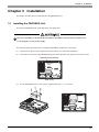
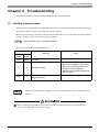
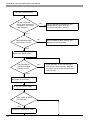
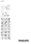
1
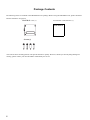
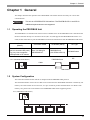
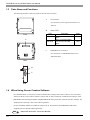
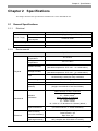
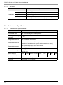
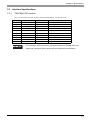
Preface Thank you for purchasing the PROFIBUS Slave unit “CA5-PFSALL/EX-01” (hereafter referred to as the “PROFIBUS unit”). This unit is intended for use with expansion interface of the Pro-face’s GP3000 series programmable operator interface (hereafter referred to collectively as the “GP”), and as an interface between the PROFIBUS data network and any of the above mentioned GPs. Before actually beginning to use the PROFIBUS unit, please be sure to read through this manual and other related manuals to fully understand all the settings and functions. NOTICE 1. Copying this manual’s contents, either in whole or in part, is prohibited without the express permission of Digital Electronics Corporation, Japan. 2. The information contained in this manual is subject to change without notice. 3. If you find any errors or omissions in this document, please contact Digital Electronics Corporation to report your findings. 4. Regardless of those above, Digital Electronics Corporation shall not take responsibility for any damage, losses or third-party’s damage resulting from the use of this product. Product names used in this manual are the trademarks / registered trademarks of their respective owners. © 2005 Digital Electronics Corporation. All rights reserved. 1 Essential Safety Precautions All safety-related procedures stated in this document must be followed to operate the PROFIBUS unit correctly and safely. Be sure to read this and any related documents thoroughly to understand the correct operation and functions of the PROFIBUS unit. Safety Icons Throughout this manual, these icons provide essential safety information for PROFIBUS unit operation procedures requiring special attention. These icons indicate the following levels of danger: Indicates situations where severe bodily injury, death or major equipment damage can occur. Indicates situations where slight bodily injury or minor equipment damage can occur. Indicates actions or procedures that should NOT be performed. Indicates actions or procedures that MUST be performed to ensure correct unit operation. Due to the possibility of an electrical shock, be sure that the power supply for the GP is not plugged in when installing the PROFIBUS unit. Be sure to design your system so that a communication fault between GP and external device (PLC etc.) will not cause equipment to malfunction. This is to prevent any possibility of bodily injury or equipment damage. Do not modify the PROFIBUS unit. Doing so may cause a fire or an electric shock. General Safety Precautions Do not allow water, liquids, or metal particles to enter into the PROFIBUS unit’s case, otherwise it can cause a malfunction or electrical shock. Avoid storing or operating the PROFIBUS unit in locations where it will be exposed to direct sunlight, high temperature, excessive dust, or vibration. 2 Avoid storing or operating the PROFIBUS unit in locations where it would be exposed to excessive temperature and dew condensation happens. Do not store or operate the PROFIBUS unit where chemicals or acids are stored, or where high concentrations of fumes are present. Because the PROFIBUS unit is a precision instrument, do not store or operate it in locations where something may strike or hit the unit. Do not use paint thinner or organic solvents to clean the outside of the PROFIBUS unit. Instead, soak a soft cloth in a diluted neutral detergent, wring it tightly, and then wipe the unit’s outside case. Unit Disposal When the product is disposed of, it should be treated as industrial waste products. Therefore, you are requested to obey the disposal standards or regulations of your country. Information Symbols This manual uses the following icons: Indicates a warning or a product limitation. Be sure to follow the instructions given with this icon to ensure the safe operation of the PROFIBUS unit. Contains additional or useful information. (1) (2) Indicates steps used to accomplish a given task. Be sure to follow these steps in the order they are written. *1 Indicates useful or important supplemental information. SEE Indicates pages containing related information. External Device Indicates the PROFIBUS-DP Master CPU (PLC etc.), which connects a GP with PROFIBUS unit. GP-Pro EX Indicates the Screen editor program for Pro-face’s GP3000 series. 3 Package Contents The following items are included in the PROFIBUS unit’s package. Before using the PROFIBUS unit, please check that all items listed here are present. PROFIBUS Unit (1) User Manual <This Manual> (1) User Manual Screws(4) This unit has been carefully packed, with special attention to quality. However, should you find anything damaged or missing, please contact your local distributor immediately for service. 4 UL/c-UL Approval The PROFIBUS unit “CA5-PFSALL/EX-01” is a UL/c-UL listed product. (UL File No. 182139, UL File No. 220851) Product Model No. UL Registration Model No. CA5-PFSALL/EX-01 3383202 This product conforms to the following standards: • UL508 Standard for Industrial Control Equipment • UL1604 Standard for Electrical Equipment for Use in Class I and II, Division 2, and Class III Hazardous (Classified) Locations • CSA-C22.2 No.14-95M (c-UL Listed) Industrial Control Equipment • CSA-C22.2 No.213-M1987 (c-UL Listed) Non-Incendive Electrical Equipment for Use in Class I, Division 2 Hazardous Locations <Cautions> Be aware of the following items when building the GP into an end-use product: • The GP unit's rear face is not approved as an enclosure. When building the GP unit into an end-use product, be sure to use an enclosure that satisfies standards as the end-use product's overall enclosure. • The GP unit must be used indoors only. • Install and operate the GP with its front panel facing outwards. • If the GP is mounted so as to cool itself naturally, be sure to install it in a vertical panel. Also, it's recommended that the GP should be mounted at least 100mm away from any other adjacent structures or machine parts. The temperature must be checked on the final product in which the GP is installed. <UL1604/CSA-C22.2, No.213 - Compliance and Handling Cautions> • Power and input/output wiring must be in accordance with Class I, Division 2 wiring methods - Article 501-4(b) of the National Electrical Code, NFPA 70 within the United States, and in accordance with Section 18-152 of the Canadian Electrical Code for units installed within Canada. • Suitable for use in Class I, Division 2, Groups A, B, C, and D Hazardous Locations, or Non-Hazardous Locations. • WARNING: Explosion hazard-substitution of components may impair compliance to Class I, Division 2. • WARNING: Explosion hazard-when in hazardous locations, turn the power OFF before replacing or wiring modules. • WARNING: Explosion hazard-confirm that the power supply has been turned OFF before disconnecting equipment, or confirm that the location is not subject to the risk of explosion. 5 • This unit is only to be mounted to this same manufacturer’s UL listed Class I, Division 2 Groups A, B, C and D panels. CE Marking The PROFIBUS unit “CA5-PFSALL/EX-01” is CE marked product that conforms to EMC directives, EN55011 Class A and EN61000-6-2. For detailed CE marking information, please ask your local GP distributor. 6 Contents Preface........................................................................................................... 1 Essential Safety Precautions......................................................................... 2 Information Symbols...................................................................................... 3 Package Contents ......................................................................................... 4 UL/c-UL Approval .......................................................................................... 5 CE Marking.................................................................................................... 6 Contents ........................................................................................................ 7 Chapter 1 General 1.1 Operating the PROFIBUS Unit .......................................................................... 9 1.2 System Configuration ........................................................................................ 9 1.3 Parts Name and Functions .............................................................................. 10 1.4 When Using Screen Creation Software ........................................................... 10 Chapter 2 Specifications 2.1 General Specifications ......................................................................................11 2.1.1 Electrical ................................................................................................................ 11 2.1.2 Environmental ........................................................................................................ 11 2.1.3 Structural................................................................................................................ 12 2.2 Performance Specifications ............................................................................. 12 2.2.1 Transmission Specifications................................................................................... 12 2.3 Interface Specifications.................................................................................... 13 2.3.1 PROFIBUS-DP interface ....................................................................................... 13 2.4 Dimensions ...................................................................................................... 14 2.4.1 PROFIBUS Unit External Dimensions ................................................................... 14 Chapter 3 Installation 3.1 Installing the PROFIBUS Unit .......................................................................... 15 3.2 Wiring for PROFIBUS-DP ............................................................................... 16 Chapter 4 Troubleshooting 4.1 No Data Communication.................................................................................. 17 7 Memo 8 Chapter 1 General Chapter 1 General This chapter describes the operation of the PROFIBUS unit and the cautions necessary for correct data communication. • This unit is a PROFIBUS DP-V0 interface. The PROFIBUS DP-V1 and DP-V2 additional requirements are not supported. 1.1 Operating the PROFIBUS Unit The PROFIBUS is an extended unit of the Pro-face’s GP3000 series. If the PROFIBUS unit is attached to the GP and connected directly to a connection device (PLC etc) that supports the PROFIBUS-DP master via a cable, the GP will be able to join the PROFIBUS network and communicate with the PROFIBUS-DP master. Host Computer (Master) Connection Cable Siemens Simatic Series (All CPU that have DP ports) e.g.) Any Host computers corresponded to DP master See “3.2 Wiring for PROFIBUS-DP” PLC (PROFIBUS-DP Master) I/F Module (Slave) GP Type PROFIBUS unit (CA5-PFSALL/EX-01) GP3000 Series PROFIBUS unit GP Cable Attachment 1.2 System Configuration The connection method for the network is complied with the PROFIBUS-DP protocol. The maximum number of slave devices that can be connected to the PROFIBUS-DP master is limited by I/O memory size of the master device. However, it’s up to 4 units for packet communication. For details of the memory size, please refer to the manual of each PROFIBUS-DP master supporting device. PLC (PROFIBUS-DP Master) GP GP GP GP 9 PROFIBUS Unit for GP3000 Series User Manual 1.3 Parts Name and Functions The following describes each parts name of the unit and its function. A. GP connector For connection to the expansion interface of a GP unit. B. Status LED LED Front PWR-LED A ERR-LED C. Functions When power ON, the LED lights. When a communication error occurs, the LED lights. Color Green Red PROFIBUS I/F Connectors For connection to a PROFIBUS lead or user fabricated cable. Rear '44 294 B C Side 1.4 When Using Screen Creation Software For communication, it’s necessary to make communication settings such as Slave Adrress, I/O size, Packet Transfer with the screen creation software, GP-Pro EX. In order to make the communication settings, select [PROFIBUS International] for Maker and [PROFIBUS DP Slave] for Series in the Deviece/PLC Settings. For further detail of the setup, refer to the following manual. For the installation method of a GSD file, please refer to the manual of each PROFIBUS-DP master supporting devices and the following manual.. SEE 10 “GP-Pro EX Device/PLC Connection Manual” Chapter 2 Specifications Chapter 2 Specifications This chapter describes the specifications and dimensions of the PROFIBUS unit. 2.1 General Specifications 2.1.1 Electrical Items Power Supply 2.1.2 Specifications Rated Voltage DC5V ± 5%(supplied by the GP unit) Power Consumption Less than 2.4W Voltage Endurance AC500V 20mA for 1 minute Insulation Resistance More than DC500V 100MΩ Environmental Items Ambient Operating Temperature Storage Temperature Physical -20°C to +60°C 10%RH to 90%RH (Wet bulb temperature: 39°C max. - no condensation.) Storage Humidity 10%RH to 90%RH (Wet bulb temperature: 39°C max. - no condensation.) Pollution Degree Less than 0.1mg/m3 No electrically conductive dusty conditions Pollution Degree 2 Atmosphere Free of corrosive gas Atmosphere (altitude) 800 - 1114 hPa. (Height: at an altitude of less than 2000m) Vibration Resistance Comply with JIS B 3502, IEC61131-2 When vibration is NOT continuous 10 - 57Hz 0.075mm 57 - 150Hz 9.8m/s2 When vibration is continuous 10 - 57Hz 0.035mm 57 - 150Hz 4.9m/s2 10 - 25Hz X, Y, Z directions for 10 times (80min.) Impact Resistance Electrical 0°C to 50°C Ambient Humidity Dust Mechanical Specifications Comply with JIS B 3502, IEC61131-2 (147m/s2 to twice X, Y, Z each directions) Noise Immunity (via noise simulator) Noise Voltage: 1,200Vp-p Pulse Duration: 1µs Rise Time: 1ns Electrostatic Discharge Immunity Contact Electrical Discharge 6kV (complies with IEC61000-4-2 Level 3) 11 PROFIBUS Unit for GP3000 Series User Manual 2.1.3 Structural Items Installation Specifications Installation method Screw fixing Cooling Method Natural air circulation Weight Approx. 500g [1.1lb] External Dimensions W88.2mm [3.47in.] x H91mm [3.58in.] x D21.1mm [0.83in.] (excluding profection and connecter part) 2.2 Performance Specifications 2.2.1 Transmission Specifications Items The number of connectable units Max. 32 units/ segment (without repeaters) Max. 125 units/ segment (with repeaters) The range of exchange numbers 1 - 125 Transmission channel configuration Bus configuration (Multi drop) Transmission channel Bus transmission channel: Twisted pair cable with shield (Extension of whole channel depends on the transmission speed) Transmission method Half-duplex transmission, Serial transmission, and comply with EIA RS-485 Transmission setting Data length: 8 bits Parity: Even number Stop bit: 1 bit Baud rate (bps)/ Transmission length 12 Specifications 9.6K 19.2K 1200m 93.75K 187.5K 500K 1.5M 1000m 400m 200m Encoding method NRZ (Non Return Zero) method I/O points Input-Output: 1 to 112 words 3M 6M 100m 12M Chapter 2 Specifications 2.3 Interface Specifications 2.3.1 PROFIBUS-DP interface D-sub 9-pin socket connector is used. (Stacking Metal Fittings : #4-40 inch screw) Pin No. 1 2 3 4 5 6 7 8 9 Shell Signal Name NC NC RxD/TxD+ CNTR-P GND +5V NC RxD/TxDNC FG Direction Input/Output Output Output Input/Output - Details Send / Receive Data (+) Repeater control signal GND +5V Send / Receive Data (-) Frame Ground • For connection of this unit and any equipment related to PROFIBUS-DP, use cables and connectors which comply with the PROFIBUS specifications. 13 PROFIBUS Unit for GP3000 Series User Manual 2.4 Dimensions The following figures show the dimensions of the PROFIBUS unit. 2.4.1 PROFIBUS Unit External Dimensions Unit: mm [in.] Upper (35 [1.38]) (5 [0.20]) 88.2 [3.47] 21.1 [0.83] 91 [3.58] '44 294 Side (left) Front Bottom 14 Side (right) Rear Chapter 3 Installation Chapter 3 Installation This chapter describes how to install and wire the PROFIBUS unit. 3.1 Installing the PROFIBUS Unit To install the PROFIBUS unit in the GP, follow the steps below. Due to the possibility of an electrical shock before installation, be sure the GP’s power cord is not plugged in to the power supply. The following figure describes how to install the PROFIBUS module into a GP-3500T. (1) Disconnect the power cable and place the GP face down on a flat horizontal surface. (2) Insert the GP connector of the PROFIBUS unit into the Expansion Unit interface on the back of GP. Expansion unit interface Rear of GP (3) Fix the PROFIBUS unit by four screws. (Tightening torque : 0.5 ~ 0.6N•m) 15 PROFIBUS Unit for GP3000 Series User Manual 3.2 Wiring for PROFIBUS-DP Be sure to earth the FG of the external device (PLC etc. ) according to Class 3 earthing standards. For details, please refer to the manual of the device/PLC used. Collect all the data cable’s shield wires and connect them to the FG of the external device (PLC etc. ). • For connection of this unit and any equipment related to PROFIBUS-DP, use cables and connectors which comply with the PROFIBUS specifications. Cable Specification This specification corresponds to the EN50170 standards. Type A cable for PROFIBUS-DP Impedance 135 to 165 Ω/ 3 to 20 Mhz Capacitance < 30 pF/m Resistance > 110 Ω/km Conductor Diameter > 0.64mm Conductor Area > 0.34mm2 Wire Connection Diagram The following wire connection diagram should be used when making a cable for the PROFIBUS. Host (Master) Signal Pin Name 16 Slave Shield Pin Signal Name 3 RxD/TxD+ 3 RxD/TxD+ 5 GND 5 GND 6 +5V 6 +5V 8 RxD/TxD- 8 RxD/TxD- Chapter 4 Troubleshooting Chapter 4 Troubleshooting The following section describes standard problems and their possible solutions. 4.1 No Data Communication When GP doesn't communicate with PROFIBUS-DP master, use the following status LED Table and troubleshooting flowchart to diagnose the problems and find the solution. When the error message is displayed on the GP screen, confirm the error code and take appropriate measures. For Error messages, please refer to the following manual.. SEE “GP-Pro EX Device/PLC Connection Manual” There are 2 status LEDs on the PROFIBUS unit. Status LED ERR (Red) PWR (Green) Not lit Not lit Meaning Cause No Power. lit lit No data exchange. Not lit lit The connection is correct and data are being exchanged. - Bus Disconnected - Master not Available / switched off - Master’s I/O communication size setting and GP’s disagree - Master’s slave address setting and GP’s disagree • This flowchart describe the coping process for the trouble that has cause on PROFIBUS unit or GP unit. Before installing the PROFIBUS unit, due to the possibility of electrical shock, be sure the GP unit power cord is unplugged from the power supply. 17 PROFIBUS Unit for GP3000 Series User Manual No Data Communication Has the connection device been configured accurately in the Screen editor program? NO Select “PFOFIBUS International“ and “PROFIBUS DP slave” about the connection device/PLC settings. YES Has PROFIBUS cable been wired correctly? NO Wire PROFIBUS cable correctly and connect the connector firmly. YES Turn Off GP’s power supply. (Remove the Power cord.) Has PROFIBUS unit been installed properly on GP? NO YES Remove the PROFIBUS Cable temporarily if connected. Turn ON GP’s power supply . Is the “PWR” & “ERR” LED light ON? YES Connect the PROFIBUS Cable. 18 NO Check that none of the connector pins have become bent or broken. Reinstall the unit on the GP so that its connector is fitted correctly. Chapter 4 Troubleshooting Is the “ERR” LED light ON? NO YES Is the network configured correctly? NO YES Is Data Transfer being performed normally? NO YES Is the “ERR” LED light OFF? Check the error message displayed on GP and perform the suggested possible solution and configure the network correctly. For further detail of the setup, refer to "GP-Pro EX Device/PLC Connection Manual.” Contact your local distributor for assistance and possible replacement of the PROFIBUS unit. NO Assuming you got an authorized replacement. YES OK/Finished Is Data Transfer of the new unit being performed normally? NO YES The original PROFIBUS unit is defective. The GP unit may be defective. Contact your local distributor for further assistance. 19 PROFIBUS Unit for GP3000 Series User Manual Memo 20