1
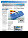
LM Bluetooth Development Kit User’s Manual
1. Product Layout
E
D
F
C
H
G
B
I
J
A
K
L
Label
A
B
C
D
E
F
Function
Power indicator LEDs
AC to DC power adaptor input
USB mini cable socket
DB9 female socket
Signal level selector
Reset button for Bluetooth module
Label
G
H
I
J
K
L
Function
LM780 Bluetooth Module
LM400 Bluetooth Module
LM071 Bluetooth Module
Socket for Jig
Pin extension
Transmit and Receive indicator
A – consist of 2 small LEDs to indicator power on this Development board. Green LED
represent 5V while Red LED represent 3.3V.
B – DC power adaptor socket, user may plug in standard AC to DC adaptor. It has
polarity protection.
C – USB Mini socket. User may connect the USB cable. It provides power to
development board and bluetooth module. It will become a COM port on computer.
However, it might need to install the FT232 driver on the computer. The driver can be
downloading at http://www.ftdichip.com. If the power required is not over 400-500mA,
user do not require to power the development kit with extra power source.
D – DB9 female socket. User may choose RS232 standard by using serial cable provided
to interface Development kit with computer. However, using this method, power source
need to be supply from DC power adaptor or the 5V pin.
E – Is a jumper to select the 5V or 3.3V voltage level of communication (Transmit and
Receive). Please refer to schematic provided for details.
F – reset button for Bluetooth module.
G – Is mounting area for LM780 Bluetooth module. Soldering is needed. Only one
Bluetooth module should be mount on Bluetooth Development kit at a time. The white
dot at PCB represents the first pin of the module.
H – is mounting area for LM400. No soldering required as the 2x6 header socket is ready.
Ensure the orientation of module is correctly installed before power up the board. Only
one Bluetooth module should be mount on Bluetooth Development kit at a time. The
white dot at PCB represents the first pin of the module.
I – is mounting area for LM071 Bluetooth module. Soldering is needed. Only one
Bluetooth module should be mount on Bluetooth Development kit at a time. The white
dot at PCB represents the first pin of the module.
J – is plug in socket for detachable jig. Please ensure the orientation of jig is correct
before power up the board. Only one Bluetooth module should be mount on Bluetooth
Development kit at a time.
K – are 2 rows of soldering pad. These pins are pins from Bluetooth module. User can
either use turn pin or header pin supplied together. Soldering is required.
L – are 2 LEDs that indicate transmit and receive activity through USB. Green LED
indicator transmit activity (from USB to Bluetooth), Red LED indicator receive activity
(from Bluetooth to USB).
Using Development board
Power
1. This board can be powered from:
a) Mini-USB
b) DC adaptor (6.5V to 12V)
c) External regulated 5V – connected from 5V embedded host such as
microcontroller board through header pin or turn pin at “K”
2. Both DS1 (5V) and DS2 (3.3V) LED will light up once the board is powered up
Bluetooth Connection
1. Please take note that only ONE bluetooth module can be mounted on this board at a
time. The module can either be soldered onto the pads provided or mounted using jig
and socket provided
2. The Bluetooth module will be powered up once the board is powered up
3. Please ensure the orientation of the jig is correctly plugged before powering up the
board. The module should be located at the right side of the board. Please refer to the
photo shown
4. The orientation of the bluetooth is indicated by the white dot on the PCB, where its
location denotes pin 1 of the Bluetooth
Communication to Host
1. On the basis, this board has built-in UART communications for all three Bluetooth
module (LM780, LM400 and LM071.
2. The UART can be accessed by:
a) Mini USB
b) Serial Port (DB9)
c) Externally through side PCB pad at “K”
3. In order to use the USB for communication, user needs to have a driver installed on
the intended host. The driver is included in CD attached, nevertheless, it can also be
downloaded at: http://www.ftdichip.com/Drivers/CDM/CDM%202.04.16.exe
4. Two LEDs, TX and RX indicate the status of USB’s UART, whereby they will each
blink respectively when data transfer is detected on the USB’s UART
5. The UART can also be accessed externally. Likewise, every port of the bluetooth
module can be accessed at both sides of the board through PCB pad at “K”.
Depending on user preference, header pin or turn pin can be soldered at this area.
6. The Voltage Selector (Refer to board layout, “E”) is used to select the TTL for
external UART. Place the jumper at 3.3V, if user wish to connect to 3.3V external
TTL or 5V, if user wish to connect to 5V external TTL
Others
1. The RESET button is pressed if user choose to reset the Bluetooth module
2. For detail connection, please refer to the schematic given