1
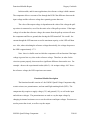
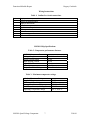
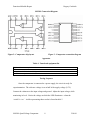
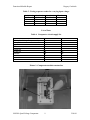
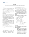
Functional Module Report
Gregory Crachiolo
USER MANUAL
FOR
THE LM2901 QUAD VOLTAGE COMPARATOR
FUNCTIONAL MODULE
LM2901 Quad Voltage Comparator
1
5/18/04
Functional Module Report
Gregory Crachiolo
TABLE OF CONTENTS
1. Index of Figures………………………………………………….………...3
2. Index of Tables………………………………………………….…………3
3. Introduction……………………………………………………….………. 4-5
4. Theory and Predictions……………...………………………….………... 5-6
5. Functional Module Description………………………………..………… 6
6. Wiring Instructions…………………………………………….………….7
7. LM2901 Chip Specifications……………………………………………... 7
8. LM2901 Connection Diagram…………………………………………….8
9. Apparatus ………………………………………………………….……... 8
10. Testing Sequence……………………………………………..……………8-9
11. List of Parts…………………………………………………….…….…….9
12. References……………………………………………………….….……... 10
LM2901 Quad Voltage Comparator
2
5/18/04
Functional Module Report
Gregory Crachiolo
Index of Figures
Figure 1 Circuit Diagram for Basic Comparator Function………………..5
Figure 2 Comparator Chip Schematic………………………………………8
Figure 3 Comparator Connection Diagram………………………………...8
Index of Tables
Table 1
Wiring Outline……………………………………………………..7
Table 2
Comparator Performance Features………………………………7
Table 3
Maximum Comparator Specifications……………………………7
Table 4
Functional Equipment List…………………………………….…..8
Table 5
Testing Sequence…………………………………………………...9
Table 6
Supply List………………………………….………………………9
Index of Images
Picture 1 Comparator Module Construction……………………………….9
LM2901 Quad Voltage Comparator
3
5/18/04
Functional Module Report
Gregory Crachiolo
Introduction
Comparators have many practical applications which mostly include
implementation of instrumentation systems. However, comparators may also be used for
timing and vibration.
Many of the internal components of a voltage comparator are transistors. Every
transistor has a base, emitter, and collector. The output of the comparator is connected to
the collector of the last transistor in the chip. If a pull-up resistor is not connected to the
output, the comparator will not function properly. This is called an open collector output.
For the situation in this module, the input voltage is a DC signal. The purpose of
the comparator circuit is to evaluate the difference between the input voltage and the
reference voltage. In a comparator, different input voltages yield different outputs. For
input voltages that are significantly larger than the reference voltage, the output voltage
will be high—the LED will illuminate. For input voltages that are smaller than the
reference voltage, the output of the comparator will be low—the LED will be off. For the
purposes in this laboratory, the comparator becomes a light ‘switch.’
Comparators, however, are not mainly used for illumination. The LED serves as
a tool to visualize what is happening. Without the LED, the output could still be
quantified. However, an LED allows observation of the output without making specific
measurements. For practical applications, a microcontroller is connected to the output
from a comparator. The high or low voltage input to the microcontroller will cause
different responses.
LM2901 Quad Voltage Comparator
4
5/18/04
Functional Module Report
Gregory Crachiolo
+5 V
Potentiometer
Resistor (pull-up)
3k Ω
V (in)
+2.5 V
Potentiometer
V (ref)
LED
GND
Figure 1. Circuit diagram for basic comparator function—module application
Theory and Predictions
The internal composition of a voltage comparator is, in essence, a modified
operational amplifier (op-amp) circuit. A more detailed explanation of op-amps is
provided in the corresponding module. An important note about op-amps is that they are
integrated circuits. An integrated circuit is a collection of individual and electronic
circuits that are composed on a single wafer. For the purposes of this module, a thorough
discussion of these contents is not necessary. For a comparator application, as opposed to
ground (in a non-inverting operational amplifier), a reference voltage is applied to the
negative terminal.
LM2901 Quad Voltage Comparator
5
5/18/04
Functional Module Report
Gregory Crachiolo
In this module, and for most applications, the reference voltage is held constant.
The comparator allows a current to flow through the LED if the difference between the
input voltage and the reference voltage has a quantity greater than zero.
The value of the output voltage is dependent on the value of the voltage the pullup resistor is connected to, as well as the static value of the pull-up resistor. If the input
voltage is less than the reference voltage, the current from the pull-up resistor will enter
the comparator and flow to ground, thus leaving the LED turned off. Be careful: the
current through the LED must not exceed its maximum capacity, or the LED will burn
out. Also, when calculating the reference voltage theoretically, the voltage drop across
the LED is approximately 1.7 V.
Note: there is a buffer zone in which the comparator will not function if the input
voltage is greater but very close to the reference voltage. Therefore, in order for the
circuit to operate properly, there must be a significant difference between the two. For
example: observe the experimental results (table 5)—for an input voltage .06 V above
the reference voltage, the LED experiences no current.
Functional Module Description
The functional module consists of: the LM2901 Quad Voltage Comparator chip,
a static resistor, two potentiometers, and one small light emitting diode (LED). The
comparator chip requires a supply voltage (5 V) and ground (0 V), as well as the input
and reference voltages. The potentiometers are used to vary the input voltage by
changing its internal resistance so as to set the reference and input voltages. Resistors are
used to protect the circuit, as well as vary the output.
LM2901 Quad Voltage Comparator
6
5/18/04
Functional Module Report
Gregory Crachiolo
Wiring Instructions
Table 1: Outline for circuit connections.
Red
Black
Yellow
Supply to the comparator, 5V
Input to the potentiometers
Supply to 3kΩ resistor
Comparator to ground, 0V
Potentiometers to ground
LED to ground
Potentiometers to input and reference terminals
Output to resistor
Resistor to LED
LM2901 Chip Specifications
Table 2: Comparator performance features.
LM2901 Comparator Features
Voltage Range
Supply Current Drain
Input Biasing Current
Input Offset Current
Offset Voltage
Output Saturation Voltage
2-36 Vdc or ±1- ±18 Vdc
.8 mA
25 nA
±5 nA
±3 mV
250 mV at 4 mA
Table 3: Maximum comparator ratings.
Absolute Maximum Ratings
Supply Voltage
Differential Input Voltage
Storage Temperature Range
Lead Temperature (soldering 10 sec)
Operating Temperature Range
LM2901 Quad Voltage Comparator
7
36 Vdc or ±18 Vdc
36 Vdc
-65 °C to 150 °C
260 °C
-40 °C to 85 °C
5/18/04
Functional Module Report
Gregory Crachiolo
LM2901 Connection Diagram
Figure 2: Comparator chip layout.
Figure 3: Comparator connection diagram
Apparatus
Table 4: Functional equipment list.
Digital multimeter or equivalent voltmeter
Power source
Voltage box with 5V outlet and 0V ground
Constructed comparator circuit box
Testing Sequence
Once the comparator is connected to a power supply, the circuit is ready for
experimentation. The reference voltage is set at half of the supply voltage (2.5V).
Connect the voltmeter to the input voltage and ground. Adjust the input voltage, while
monitoring its level. Notice the voltage at which the LED illuminates—when the
‘switch’ is ‘on.’ A table representing these results is found in table 5.
LM2901 Quad Voltage Comparator
8
5/18/04
Functional Module Report
Gregory Crachiolo
Table 5: Testing sequence results for a varying input voltage.
V(ref) [Volts]
2.5
2.5
2.5
2.5
V(in) [Volts]
1
2.5
2.57
4
V(out) [Volts]
0.14
0.14
3.08
3.08
LED on?
no
no
yes
yes
List of Parts
Table 6: Comparator circuit supply list.
Part
LM2901 Quad Voltage Comparator Chip
Pull-up Resistor
Potentiometer
LED
Voltage Box
Breadboard
Red Wire
Black Wire
Yellow Wire
Voltmeter
Value
N/A
3000
50,000
N/A
5
N/A
N/A
N/A
N/A
N/A
Unit
N/A
Ω
Ω
N/A
V
N/A
N/A
N/A
N/A
N/A
Picture 1: Comparator module construction
LM2901 Quad Voltage Comparator
9
5/18/04
Functional Module Report
Gregory Crachiolo
References
RIZZONI, GIORGIO. (2000) Principles and Applications of Electrical Engineering.
3rd Edition. Boston, MA. McGraw-Hill, 2000.
National Semiconductor: LM2901 Comparator Data Sheet.
http://cache.national.com/ds/LM/LM139.pdf
LM2901 Quad Voltage Comparator
5/18/04
10