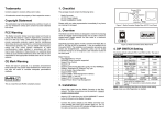
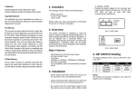
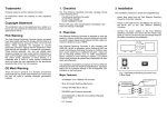
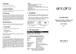
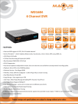
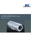
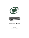
1
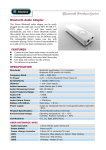
Trademarks 1. Checklist CTS is a registered trademark of Connection Technology Systems Inc. Contents subject to revision without prior notice. The package should contain the following items: All other trademarks remain the property of their owners. Copyright Statement Copyright Connection Technology Systems Inc. This publication may not be reproduced as a whole or in part, in any way whatsoever unless prior consent has been obtained from Connection Technology Systems Inc. FCC Warning The CVT-3002-PLUS Series converters have been tested and found to comply with the limits for a Class A digital device, pursuant to Part 15 of the FCC Rules. These standards are designed to provide reasonable protection against harmful interference when these devices are operated in a commercial environment. These devices generate, use, and can radiate radio frequency energy and may cause harmful interference to radio communications unless installed in accordance with this User’s Guide. Operation of these devices in a residential area is likely to cause harmful interference which will make the user responsible for the appropriate remedial action at his / her own expense. CE Mark Warning These are Class A products. In a domestic environment these products may cause radio interference in which case the user will need to consider adequate preventative methods. - CVT-3002-PLUS Converter AC-DC Power Adapter User’s Guide Figure 1. CVT-3002-PLUS dual fiber Front Panel Please notify your sales representative immediately if any items are missing or damaged. 2. Overview CVT-3002-PLUS is designed to meet the massive needs for Gigabit network deployment and able to extend a copper based Gigabit network via fiber cable to a maximum distance up to 80KM. Figure 2. CVT-3002-PLUS WDM & SFP Front Panel CVT-3002-PLUS is fully compliant with IEEE802.3, 802.3u, 802.3ab & 802.3z standards. It can be installed into a CVT Converter RACK. The installation & operation procedures are simple & straightforward. Operation status can be locally monitored through a set of Diagnostic LED located in the front panel. Figure 3. CVT-3002-PLUS Converter Rear Panel Major Features: - 4. DIP SWITCH Setting Auto-Negotiation in TX port MDI/MDIX Auto-Crossover supported Support Flow Control Support Link Alarm Support Jumbo Frame 9K bytes (under 10,100,1000Mbps) Store and Forward Switching Mechanism Support Auto & Force mode configuration 3. Installation - Attach fiber cable from the CVT-3002-PLUS to the fiber network. The fiber connections must be matched – transmit socket to receive socket. - Attach a UTP cable from the 10/100/1000BASE-T network to the RJ-45 port on the CVT-3002-PLUS. - Connect the power adapter to the CVT-3002-PLUS and check that the Power LED lights up. The TX Link/Act and F/O Link/Act LEDs will light up when all the cable connections are satisfactory. The default setting for PIN 1 and 6 is ON. The rest of Pins are OFF. Pin NO. Function OFF ON TP Auto-Negotiation 1 Disable Enable 2 Manual TP speed 10M 100M 3 Manual TP speed N/A 1000M 4 Duplex mode Half Full 5 Flow Control Disable Enable 6 F/O mode Force Auto 7 Link Alarm Disable Enable Transmission Store and Pass-through 8 mode forward NOTE: 1. Before changing TP speed, duplex mode and flow control setting, please make sure PIN 1 is set to OFF. 2. When TP speed is set to 10M or 100M manually, PIN 3 needs to be turned OFF. 3. Under 1000Mbps, it supports full-duplex mode only. 4. When Pin 8 is set to ON and the TP speed to 1000M, full-duplex mode and flow control are disabled. 5. LED Description LED Color Power Green TX Link/Act FO Link/Act FDX Speed Status Fiber Transceiver Information 1000M Function Lit when power is available. Lit when TX cable connection with Green remote device is good. Blink when TX traffic is present. Lit when Fiber cable connection with Green remote device is good. Blink when F/O traffic is present. Lit when TX works in Full-Duplex. Green Not-Lit when TX works in Half-Duplex. No-Lit when TX works in 10M. Green Lit when TX works in 100M. Orange Lit when TX works in 1000M. Green Lit when TX and F/O link is up. Orange Lit when TX or F/O link is down. Multi-Mode TYPE Connector Type BTFC SC Wavelength 850nm Typical Distance 500m Min TX PWR -9.5dBm Max TX PWR -4.0dBm Sensitivity -18.0dBm Link Budget 8.5dB CVT-3002-PLUS SERIES Single-Mode TYPE BTFC(SM-10) BTFC(SM-20) BTFC(SM-30) Connector Type SC SC SC 6. Technical Specifications Standards: IEEE 802.3, 802.3u, 802.3ab, 802.3z Interface: 1 X 10/100/1000 RJ-45 connector 1 X 1000 F/O port or SFP Slot LED: Power, FDX, Status, Speed, FO Link/ACT, TX Link/ACT Power: I/P AC 100-240V O/P DC 5V, 1.6A Power Consumption: 3W Shipping Weight: 0.6KG Dimensions: 71mm(W)X94mm(D)X26mm(H) Temperature: Operating: 0o~50oC Storage: -20o~60oC Humidity: 5%~90% RH Emission: Electrical: UL, CSA EMI: FCC Class A, CE *Please contact us for further reports and updates. Media: TP EIA/TIA-568 CAT 5e, 1000M Fiber 50/125, 62.5/125um multi-mode fiber 9/125, 10/125um single-mode fiber Wavelength 1310nm 1310nm Typical Distance 10Km 20Km 1310nm 30Km Min TX PWR -9.5dBm -5.0dBm -5.0dBm Max TX PWR -3.0dBm 3.0dBm 3.0dBm Sensitivity -20.0dBm -24.0dBm -24.0dBm Link Budget 10.5dB 19.0dB 19.0dB 10/100/1000BASE-T to 1000BASE-X Standalone Media Converter Wave-Length WDM TYPE W2A(SM-10) W2B(SM-10) W2A(SM-20) W2B(SM-20) Connector Type SC SC SC SC TX Wavelength 1310nm 1550nm 1310nm 1550nm RX Wavelength 1550nm 1310nm 1550nm 1310nm Typical Distance 10 Km 10 Km 20 Km 20 Km Min TX PWR -10.0dBm -9.0dBm -7.0dBm -7.0dBm Max TX PWR -3.0dBm -3.0dBm 0dBm 0dBm -23.0dBm -23.0dBm 16.0 dB 16.0 dB Sensitivity Link Budget -22.0dBm -22.0dBm 12.0 dB 13.0 dB NOTE: Specifications may change without prior notice. Contact Information Connection Technology Systems Inc 18F-6, No.79, Sec.1, Hsin Tai Wu Rd., Hsichih, Taipei Hsien, Taiwan, R.O.C. Tel + 886 2 2698 9661 Fax + 886 2 2698 9662 E-mail [email protected] User’s Guide Version 0.95