1
Carlos III University of Madrid
Bachelor Thesis
Location based service restrictions for Android devices
Computer Engineering
February
2012/2013
Author:
Name: Francisco Sánchez Navarro
Tutor:
Name: Jorge Blasco Alís
2
Agradecimientos
Me gustaría dedicar estas líneas a todas aquellas personas que han hecho realidad este
proyecto. Durante todo este tiempo me he sentido muy apoyado tanto por familiares
como amigos, profesores y otros seres queridos que han estado a mi lado animándome,
interesándose por mis avances e incluso ofreciéndose voluntarios para probar, en
primera persona, el resultado de este proyecto.
En primer lugar, quiero dar las gracias a mis padres por todo su apoyo a lo largo de
cada uno de estos años. Gracias por haberme ayudado en momentos difíciles dónde no
tenía claro que esta carrera fuese para mí. Sin vosotros, nada de esto sería posible.
Me gustaría mencionar de forma especial a Elena, que ha estado a mi lado todo este
tiempo a pesar de la distancia. Gracias por haberme ayudado tanto en los momentos más
difíciles y darme esas fuerzas para seguir adelante.
Todos estos años de universidad han sido un largo camino. Me gustaría dar las
gracias a cada uno de los profesores que me han formado tanto profesionalmente como
personalmente. En especial, doy las gracias a Jorge por toda su paciencia respondiendo
a los miles de correos y sus ideas que han sacado adelante este proyecto.
Finalmente, agradecer a todos mis compañeros de la universidad por todas las tardes
que, a pesar de todo el trabajo, han sido muy divertidas. También a mis amigos en
Madrid y a mis compañeros de piso de Sheffield que me han aguantado durante estos
meses.
A todos vosotros, Gracias.
3
LIST OF CONTENTS
CHAPTER 1. INTRODUCTION ......................................................... 11 1.1. INTRODUCTION .................................................................................. 11 1.2. MOTIVATIONS ................................................................................... 12 1.3. PROJECT GOALS ................................................................................ 12 1.4. DOCUMENT STRUCTURE .................................................................... 13 CHAPTER 2. STATE OF ART ............................................................ 16 2.1. MOBILE DEVICES .............................................................................. 16 2.2. SIMILAR APPS .................................................................................. 17 2.2.1. Stuff on the go ......................................................................... 17 2.2.2. Tasker ...................................................................................... 17 2.2.3. Todo (Appigo) ......................................................................... 18 2.2.4. Remiders ................................................................................. 19 2.2.5. Apple Configurator ................................................................. 20 2.3. MOBILE LOCATION ........................................................................... 21 2.3.1. Cell Identification-based ......................................................... 21 2.3.2. Angle of Arrival-based ............................................................ 22 2.3.3. Received Signal Strength-based .............................................. 22 2.3.4. Time-based .............................................................................. 23 2.4. OUTDOOR LOCATION ........................................................................ 24 2.4.1. Global Positioning System ...................................................... 24 2.4.2. Mobile Network-based location .............................................. 26 2.5. INDOOR LOCATION ............................................................................ 29 2.6. GEOLOCATION API IN ANDROID ....................................................... 31 2.6.1. Location Class ........................................................................ 31 2.6.2. LocationManager Class .......................................................... 32 2.6.3. LocationListener Class ........................................................... 32 2.6.4. Wi-Fi location ......................................................................... 32 2.7. SQLITE DATABASE API .................................................................... 33 2.7.1. SQLiteOpenHelper Class ........................................................ 33 2.7.2. SQLiteDatabase Class ............................................................ 33 4
2.8. PACKAGE MANAGEMENT API ........................................................... 34 2.9. ANDROID PERMISSIONS ..................................................................... 35 2.10. GOOGLE APP ENGINE ..................................................................... 36 CHAPTER 3. PROJECT ANALYSIS ................................................. 38 3.1. SYSTEM REQUIREMENTS ................................................................... 38 3.1.1. Functional Requirements ........................................................ 40 3.1.2. Non Functional Requirements ................................................ 48 3.2. VALIDATION TESTS ........................................................................... 54 3.3. TRACEABILITY MATRIX .................................................................... 61 3.4. DEVELOPMENT METHODOLOGY ........................................................ 62 CHAPTER 4. PROJECT DESIGN ...................................................... 64 4.1. SYSTEM DESIGN ................................................................................ 64 4.2. APPLICATION DESIGN ....................................................................... 66 4.2.1. Presentation Tier .................................................................... 67 4.2.1.1. Set-Up Mobile Interface Subsystem ..................................... 68 4.2.2. Logic Tier ................................................................................ 68 4.2.2.1. System Start-Up Subsystem .................................................. 69 4.2.2.2. Service Controller Subsystem .............................................. 69 4.2.2.3. Location Manager Subsystem .............................................. 71 4.2.3. Data Tier ................................................................................. 72 4.2.3.1. Database Manager Subsystem ............................................. 72 4.3. SERVER DESIGN ................................................................................ 73 4.3.1. Server Subsystem .................................................................... 73 CHAPTER 5. PROJECT IMPLEMENTATION ............................... 75 5.1. PRESENTATION TIER ......................................................................... 75 5.1.1. Set up Mobile Interface ........................................................... 75 5.2. LOGIC TIER ....................................................................................... 76 5.2.1. System Start up ........................................................................ 76 5.2.2. Service Controller ................................................................... 77 5.2.2.1. LocEnableService ................................................................ 78 5.2.2.2. LocEnableUpdater ............................................................... 82 5
5.2.2.3. XmlParse .............................................................................. 82 5.2.2.4. Rule ...................................................................................... 82 5.2.2.5. Shell...................................................................................... 83 5.2.3. Location Manager ................................................................... 83 5.3. PERSISTENCE TIER ............................................................................ 84 5.3.1. Database Manager.................................................................. 84 5.3.1.1. DataBaseHelper ................................................................... 84 5.3.1.2. LocEnableApplication.......................................................... 86 5.4. SERVER SUBSYSTEM ......................................................................... 86 5.4.1. LocEnableServerServlet .......................................................... 87 5.4.2. LocEnableServerForm ............................................................ 87 5.5. TESTING ............................................................................................ 88 5.6. XML FILES ....................................................................................... 92 CHAPTER 6. PROJECT MANAGEMENT ....................................... 93 6.1. PROJECT PLANNING........................................................................... 93 6.2. COST PROJECTION ............................................................................. 94 CHAPTER 7. CONCLUSIONS AND FUTURE WORK .................. 96 7.1. CONCLUSIONS ................................................................................... 96 7.2. FUTURE WORK .................................................................................. 97 CHAPTER 8. APPENDICES ............................................................. 103 APPENDIX A........................................................................................... 103 A.1. USER MANUAL ............................................................................... 103 A.1.1. DEVICE APPLICATION.................................................................. 103 A.1.2. WEB APPLICATION ...................................................................... 105 APPENDIX B ........................................................................................... 109 B.1. ACRONYMS..................................................................................... 109 B.2. BIBLIOGRAPHY ............................................................................... 112 6
LIST OF FIGURES
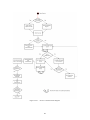
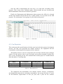
Figure 2.2.1. – Stuff on the go ................................................................... 17 Figure 2.2.2. – Tasker................................................................................. 18 Figure 2.2.3. – Todo (iTunes) .................................................................... 19 Figure 2.2.3. – Reminders .......................................................................... 19 Figure 2.2.4. – Remind Me ........................................................................ 20 Figure 2.2.5. – Apple Configurator (iTunes) ............................................. 21 Figure 2.3.2. – Angle Of Arrival ................................................................ 22 Figure 2.3.3. – Received Signal Strength ................................................... 23 Figure 2.3.4. – Time Difference of Arrival ................................................ 24 Figure 2.4.1 – GPS ..................................................................................... 25 Figure 2.4.2.1. – Multipath signals ............................................................ 27 Figure 2.4.2.2. – A-GPS ............................................................................. 29 Figure 2.5 – RFID transmision................................................................... 31 Figure 2.9.1. – Android Permissions List .................................................. 35 Figure 2.9.2. – Manifest example ............................................................... 36 Figure 3.3. – Waterfall development model ............................................... 63 Figure 4.1.1. – Rule Design........................................................................ 65 Figure 4.1.2. – System Architecture ........................................................... 66 Figure 4.2. – Application Design ............................................................... 67 Figure 4.2.1. – Presentation Tier ................................................................ 68 Figure 4.2.2. – Logic Tier .......................................................................... 68 Figure 4.2.2.1 – Restricted zone matching ................................................. 70 Figure 4.2.2.2 – Service Flow Chart (Restrict Apps) ................................. 71 Figure 4.2.3. – Service Diagram ................................................................ 72 Figure 4.3 – Server Protocol ...................................................................... 73 Figure 4.3.1 – Server Subsystem ................................................................ 74 Figure 5.1.1. – Setup Mobile Interface....................................................... 75 Figure 5.2.1. – System Start Up ................................................................. 76 Figure 5.2.2. – Service Controller .............................................................. 77 Figure 5.2.2.1 – Service Controller Flow Diagram .................................... 81 Figure 5.3.1. – DatabaseManager Subsystem ............................................ 84 Figure 5.3.1.1. – Database Relation Schema.............................................. 86 Figure 5.4. – Server Subsystem .................................................................. 87 Figure 5.6. – XML Schema ........................................................................ 92 Figure 6.1. – Gantt Chart............................................................................ 94 Figure 8.1. – Device File Manager ........................................................... 103 Figure 8.2. – Application Screen .............................................................. 104 Figure 8.3. – Root priviledges request ..................................................... 105 Figure 8.4. – Main Interface ..................................................................... 105 Figure 8.5. – Log in GAE Interface ......................................................... 105 Figure 8.6. – Application List .................................................................. 106 7
Figure 8.7. – Main interface ..................................................................... 106 Figure 8.8. – Logs interface ..................................................................... 107 Figure 8.9. – GQL Datastore interface ..................................................... 107 Figure 8.10. –Datastore interface ............................................................. 107 Figure 8.11. – Web Application interface ................................................ 108 8
LIST OF TABLES
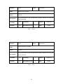
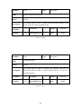
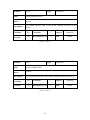
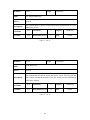
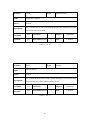
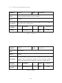
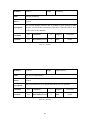
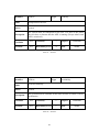
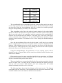
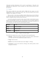
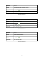
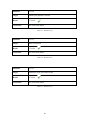
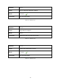
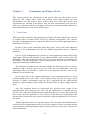
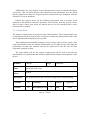
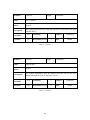
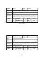
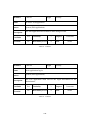
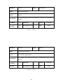
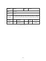
Table 1 – System Requirements Template ................................................. 39 Table 2 – FR-01.......................................................................................... 40 Table 3 – FR-02.......................................................................................... 41 Table 4 – FR-03.......................................................................................... 41 Table 5 – FR-04.......................................................................................... 42 Table 6 – FR-05.......................................................................................... 42 Table 7 – FR-06.......................................................................................... 43 Table 8 – FR-07.......................................................................................... 43 Table 9 – FR-08.......................................................................................... 44 Table 10 – FR-09........................................................................................ 44 Table 11 – FR-10........................................................................................ 45 Table 12 – FR-11........................................................................................ 45 Table 13 – FR-12........................................................................................ 46 Table 14 – FR-13........................................................................................ 46 Table 15 – FR-14........................................................................................ 47 Table 16 – FR-15........................................................................................ 47 Table 17 – NFR-01 ..................................................................................... 48 Table 18 – NFR-02 ..................................................................................... 48 Table 19 – NFR-03 ..................................................................................... 49 Table 20 – NFR-04 ..................................................................................... 49 Table 21 – NFR-05 ..................................................................................... 50 Table 22 – NFR-06 ..................................................................................... 50 Table 23 – NFR-07 ..................................................................................... 51 Table 24 – NFR-08 ..................................................................................... 51 Table 25 – NFR-09 ..................................................................................... 52 Table 26 – NFR-10 ..................................................................................... 52 Table 27 – NFR-11 ..................................................................................... 53 Table 28 – Validation Test Template ......................................................... 54 Table 29 – VT-01 ....................................................................................... 55 Table 30 – VT-02 ....................................................................................... 55 Table 31 – VT-03 ....................................................................................... 56 Table 32 – VT-04 ....................................................................................... 56 Table 33 – VT-05 ....................................................................................... 57 Table 34 – VT-06 ....................................................................................... 58 Table 35 – VT-07 ....................................................................................... 59 Table 36 – VT-08 ....................................................................................... 59 Table 37 – VT-09 ....................................................................................... 60 Table 38 – Traceability Matrix................................................................... 61 Table 39 – Basic Exceptions ...................................................................... 79 Table 40 – Restriction Flag values ............................................................. 80 Table 41 – Locations table ......................................................................... 84 9
Table 42 – Restritions table........................................................................ 85 Table 43 – Exceptions table ....................................................................... 85 Table 44 – Locres table .............................................................................. 85 Table 45 – Locexc table ............................................................................. 85 Table 46 – Device table Datastore ............................................................. 87 Table 47 – Validation Test Result Template ............................................. 88 Table 48 – Result VT-01 ............................................................................ 89 Table 49 – Result VT-02 ............................................................................ 89 Table 50 – Result VT-03 ............................................................................ 89 Table 51 – Result VT-04 ............................................................................ 90 Table 52 – Result VT-05 ............................................................................ 90 Table 53 – Result VT-06 ............................................................................ 90 Table 54 – Result VT-07 ............................................................................ 91 Table 55 – Result VT-08 ............................................................................ 91 Table 56 – Result VT-09 ............................................................................ 91 Table 57 – Human Resources..................................................................... 94 Table 58 – Equipment Resources ............................................................... 95 Table 59 – Total Cost projection ................................................................ 95 Table 60 – FWR-01 .................................................................................... 97 Table 61 – FWR-02 .................................................................................... 98 Table 62 – FWR-03 .................................................................................... 98 Table 63 – FWR-07 .................................................................................... 99 Table 64 – FWR-04 .................................................................................... 99 Table 65 – FWR-05 .................................................................................. 100 Table 66 – FWR-06 .................................................................................. 100 Table 67 – FWR-07 .................................................................................. 101 Table 68 – FWR-08 .................................................................................. 101 Table 69 – FWR-09 .................................................................................. 102 10
Chapter 1.
Introduction
This chapter describes the different aspects of this project such as the motivations for
developing this software APP, what are the project goals and why the Android
technology have been used in order to develop the project. Finally, the document
structure will be explained in order to provide a clear idea about how this document
should be read.
1.1. Introduction
In the last few years, mobile devices have experienced great improvements. Not many
years ago, people used to work on their desktop computer since laptops were so heavy
to carry, they were less powerful and with a short battery life.
Nowadays, those constrains have disappeared and mobile devices are becoming so
popular and useful making our workspace very dynamic since we can carry all what we
need with us.
But, this does not end here, the mobile phones, that have been use for basic things
such as calls and texts, have now become a small computer in our pocket able to process
a great amount of data, running complex software and store information. This new
generation of phones are called smartphones.
Those new mobile technologies open a great new field create new applications with
different features. These applications, more commonly called APPs, give our
smartphones additional features and options allowing us to used them in very different
ways.
Also, there are new network technologies that allow all those devices to be more
connected that ever before as the 3G and the “on development” 4G networks that
provide high speed broadband and connection to Internet. In addition to all these facts
the continuous increasing cloud computing, gives us the possibility of access your data
from anywhere.
All those new improvements in the mobiles devices and network are responsible of
the new mobile devices as tablets that have become very popular.
Those new technologies do not have just advantages. In fact, there are so many
different ways to access and transmit information, that from a security point of view,
increase the security risk not only for the average user, but also for organizations that
allow its usage inside it premises.
In this project will provided the design and develop of the software that provides us
security against some of those threats by restricting some of the actions that can be
performed with the mobile devices. This software provides us control over those mobile
devices in an organization environment, in this way the user can decide which features
are not allowed to be used reducing the risk of an attack.
11
1.2. Motivations
Nowadays, Smartphones are becoming more popular and useful in our work
environment. Smartphones are used for so many different features such as an agenda,
calendars for appointment reminders, and even as a camera, as so many different APP
that can be installed in them. These APPs are becoming more powerful since the
devices are getting improved in a very fast way. We can notice that when every year
some company sells a new device that is much more powerful than the others in the
market.
Those new options in the palm of our hand make our tasks easier but also allow
others to use them in inappropriate way. As we explained above, smartphones have so
many different features and since every one can carry them in their pocket, it is a hard
work to control the way those devices are used.
This is the main motivation to develop a software able to control some devices to
prevent situations in which our information can be at risk. The software will not allow
the device to use some features that can be a potential risk, depending on the device
location or Wi-Fi connection.
The main target of this software is the business environment. For instance, since
companies have so many visitor and workers to their offices, it could be a security
improvement if they cannot use some features of their phones in order to obtain
information or use the device in a not allowed way.
This software is based on the APP permissions system used by Android and the
Geolocation feature of the devices that will be explained later on this document. The
APP will be developed for Android devices since it is running in a wide range of
devices compared to other mobile operating systems. In this way, it gives more freedom
to the company since is not force to choose among just few devices. Similar
applications can be found for other systems such as iOS but with slightly differences
that will be discussed in the section Similar APPs.
1.3. Project Goals
Nowadays, most of the people have mobile devices able to perform from the simplest
task to complex algorithms. This fact could be a risk in some situations. For instance,
the usage of the mobile devices in workstations may reduce the productivity of the
employees if they are not using it form specific working purposes. Also, visitors could
use theirs mobile devices to obtain some information that they are not allowed to have
access for their own benefit.
The aim of this project is to control the mobile devices in a specific environment
and restrict its functionalities to provide safe areas with the fewer risks as possible.
In order to archive this goal, this project designs and implements software able to
control the mobile devices based on its location. This project includes the software that
runs on the devices and the server that provides the management tools to setup all the
devices.
12
The software installed in the devices will be transparent for the device users. These
users will be able to work properly with their devices. The device will execute all the
functionalities but the ones that are restricted by the application using the device
location. When a user tries to use some functionality that is forbidden within that
location, the device will not run it and so, it will not allow the user to use that specific
functionality.
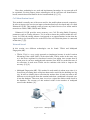
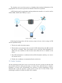
On the other side, a management tool will be provided. This tool allows the user to
setup the devices over Internet. The administrator is the one that creates the rules that
restricts the applications. Once the rules are created, the management tool allows the
administrator to attach the rules to one or more devices. Then, the management tool will
send those rules to each device. Every device is responsible of its own rules and the
device software makes sure that the rules are satisfied.
1.4. Document Structure
In this section, a brief introduction about the project environment, some motivations and
the project objectives are given. So, in this last part of the first chapter, the structure of
the document will be explained.
The document will consist of chapters, and in those chapters will be different
sections explaining parts related to the specific chapter.
• Chapter 2: State of Art.
o Mobile Devices: A brief explanation of the mobile devices situation nowadays
will be given in this section.
o Similar APPs: Some application with similar functionalities that are actually in
the market will be studied in this section.
o Mobile location: A further review about all the mobile location approaches
used nowadays and a brief explanation of the API used in the APP
development.
o SQLite Database: This section will provide an explanation of the SQLite
library in Android by explaining some of the used methods.
o Package Manager: All the information about how this library is used in
Android and its functionalities can be found in this section.
o Permissions in Android: A very important security aspect is based in
permissions. This section will describe how Android handles those
permissions.
o Google App Engine: Some technologies as GAE have been used in the server
side of the application. This section will provide further information about
those technologies.
13
• Chapter 3: Project Analysis.
o System requirements: All the needed functionalities to satisfy all the project
objectives will be shown in this section.
o Validation Test: Some validation test will be defined in this section in order to
ensure that the requirements have been accomplish when the system has been
implemented.
o Traceability Matrix: More graphically explanation of who the requirements are
tested with the validation tests.
o Development Methodology: In this section, all the steps to follow in the
development progress will be explained in details.
• Chapter 4: Project Design.
o System Design: This section will provide an explanation about how the whole
system has been designed and how it works to accomplish all the requirements.
o App Presentation Tier: All the functionalities of the Presentation Tier and its
structure will be explained in this section.
o App Logic Tier: All the functionalities of the Logic Tier and its structure will
be explained in this section.
o App Data Tier: All the functionalities of the Data Tier and its structure will be
explained in this section.
o Server Design: All the functionalities of the Server side and its structure will be
explained in this section.
• Chapter 5: Project Implementation.
o Presentation Tier: This section will provide information about how the
presentation tier module is implemented in the system.
o Logic Tier: This section will provide information about how the logic tier
module is implemented in the system.
o Persistence Tier: This section will provide information about how the
persistence tier module is implemented in the system.
o Server Subsystem: This section will provide information about how the server
module is implemented in the system.
o Testing: All the executed texts and the results will be analysed in this section.
14
• Chapter 6: Project Management.
o Project Planning: The planning followed to develop the project is provided in
this section.
o Cost Projection: A specification of all the costs involved in the project.
• Chapter 7: Conclusion and Future work.
o Conclusions: A review over the entire project will be done in this section
including a study of the objectives.
o Future Work: What can be improved and what can be added will be discuss in
this last section.
• Chapter 8: Appendix.
o User Manual: Some guidelines of how the system has to be installed and used.
o Acronyms: this section provides the explanation of the different acronyms used
in this document.
o Bibliography: This section provides a list with the resources used on this
document.
15
Chapter 2.
State of Art
This chapter will explain in more detail all the technologies used to develop the
application providing a better knowledge of how these technologies works. Also, some
APIs used in the code will be reviewed in order to clarify the usage of some specific
libraries.
2.1. Mobile Devices
Often, when someone mentions the “mobile devices”, he/she is mainly refers to the
mobile phones (smart phones), since these devices are the most popular in this group.
Many different devices such as laptops, tablets, phones or even new generation of music
players, also belong to the mobile device group.
There is no doubt that mobile phones have experienced a massive evolution since
that first hand-held mobile phone in 1973 done by Martin Cooper with the Motorola
Team [24]. This first phone cost approximately $10,000 USD, which compared to the
actual prices is a huge amount of money.
These phones have evolved but not just the hardware of the phone itself, also the
technologies around mobile phones have evolved. The first commercially automated
cellular network was launched in the early 1980s.
Then, the second generation, called 2G, used a digital transmission instead of
analogy and it was based in GSM standard. 2G networks provided the users the
transmission of media content; in 1998 the first downloadable media content was a ring
tone for phones.
The third generation called 3G was launched for the first time in Japan in 2001 and
by the end of 2007 3G networks had 295 Million subscribers. This new technology
provides users new possibilities such as the streaming.
Nowadays, the four-generation (4G) is coming out. This generation is already being
tested in some parts of Europe such as London. It improves the 3G networks, being
much faster. [25]
From the point of view of the hardware, mobile devices have also evolve very fast
being able to manage all those technologies mentioned before and being able to process
a huge amount of information.
The concept smartphone does not appear until 1997 but it is in 2007 when Apple
introduced the original iPhone, when this market made exploded, and all the big
companies such as Samsung or Nokia started being interested on what actually is
known as smartphones.
Nowadays the market of the mobile devices is huge, in 2011 29 Billion apps were
downloaded and in 2012 mobile subscribers worldwide reach 6.5 Billion worldwide. By
the end of 2016 is predicted to raise until 8 Billions of subscribers [22].
16
2.2. Similar APPs
This section explains some applications, which are in the market, that have some
features in common with the application that is being described in this document.
In the case of Android, it has been easier to find similar code and more developers
guide about how to do some specific features. Also, some similar application can be
found in iOS. Some of the most similar application will be reviewed briefly in this
section.
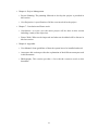
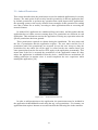
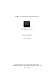
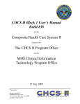
2.2.1. Stuff on the go
Since our application is mainly based in mobile location, multiple applications based on
this technology can be found nowadays in the market. “Stuff on the go” is one of those
application location-based and it is developed for Android.
This application is a simple location-based task reminder. It allows setting up a
specific location in the map and attaching to that location different features such as
simple alarms, repeated alarms, Geo-Location alerts or SMS alerts [2].
For instance, a easy task of this application should be to set a location and when the
device arrive to that point, it will deliver a SMS to notify that it is there. This
application is similar to the application described in this document because it is based
on location to perform operations.
Figure 2.2.1. – Stuff on the go
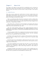
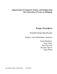
2.2.2. Tasker
This is probably the most useful application that can be found for location-based task
purposes. As the others, it is a location-based reminder but with a slight difference. This
application use external applications such as the music player. For instance, you can set
it up to launch the music player when you run out of your office. This is quite
17
interesting since our service will be working with others application based on the device
location [3].
This application is quite similar to Stuff on the go and it is also developed for
Android devices. The location process in which the application is based is quite similar
to the application described in this document.
Figure 2.2.2. – Tasker
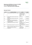
2.2.3. Todo (Appigo)
On the other side, iOS offers in millions of devices distribute applications and so many
nice application are being developed for this platform everyday.
An example of those applications developed for iOS and similar to the application
described in this document is “TODO”. This application allows us to set up alerts
attached to a location. You can configure TODO to send an alert when arriving a
specific location. A example of use is to set up to pick up your Childrens when you go
out of the work [1].
Since Appingo is a great company dedicated to develop application for iOS, this
application is one of the best developed and professional of those reviewed in this
section.
18
Figure 2.2.3. – Todo (iTunes)
2.2.4. Remiders
This is the native application of iOS with location-based alerts. This application is able
to use Date/time or location-based notifications, search for specific reminders, reorder
to-dos, view your reminders by list or date view and automatically update all your
devices and calendars synchronizing them with other external programs [5].
This is another good example of location-based reminder application. It is similar to
the app described in this document from the conceptual point of view of the location
process.
Figure 2.2.3. – Reminders
19
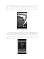
Figure 2.2.4. – Remind Me
2.2.5. Apple Configurator
All these reviewed applications have something in common and it is the location-based
process. This is a very important aspect of our application but is not the only one. Our
application also uses permissions to restrict the launch of specific application and none
of those applications do similar features. From the point of view of restriction and
security there is one application that has similar goals as our application has.
This application allows managing easily iOS devices such as iPhones, iPads and
iPods touch. Apple configurator can prepare new iOS devices for distribution or
supervise devices that need to maintain a standard configuration not allowing the user to
modify this configuration. This feature is quite similar to what the application described
in this document does from the point of view of restrictions [21].
This application also can restrict the applications that are installed into the device.
This rules can be apply to a specific device or to a full series of different devices, it also
keeps them up-to-date in case the restrictions change. This mechanism of controlling
devices is close to the idea developed in this document.
Another important point is that the previous application are more focused in the user
market, the application is downloaded and installed for the user of the phone and that
user is the one who benefits from the application. In this case, as in our application, the
direct beneficiary of the application is the one who wants to control the devices. For
instance, the company may install the application in the devices of its employees in
order to help or control them on the working environment.
20
Figure 2.2.5. – Apple Configurator (iTunes)
2.3. Mobile Location
There are different location methods and different applications for them. Despite the
fact that it is not the same to locate a device in a great city than locate a boat in the
middle of the sea, both cases have some location method in common. Some of the
location approaches are based in cell identification, angle of arrival, signal strength and
time of propagation. Also, those approaches can be combined to create new hybrid
location methods that can be more effective or less resource consuming [6] [8].
In this section, some of the most important methods of location will be explained in
order to provide a clear idea about how our system is working.
2.3.1. Cell Identification-based
This location method uses cell identification or access point, if we are talking about
WLANs to get a location point. The location point is given by the identity of the cell
that is connected with the phone device. Each cell has a specific ID so knowing the cell
ID, which is connected to the phone, the position of the phone can be approximated
depending of the cell type. This method is known as Cell Global Identity (CGI).
This approach is easy to implement since it does not require change in the structure
of the network or device. The accuracy of this method could vary depending of the cell
type, in metropolitan areas it could be meters but in the rural area it will have a very
poor accuracy.
Cell identification-based methods are one of the most used by the GSM-phones
companies, since it is enough to provide the user with basic services on metropolitan
21
areas. On the third generation networks other more accurate approached can be used
[11] [12].
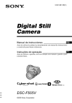
2.3.2. Angle of Arrival-based
This method is also called Direction of Arrival (DOA), it uses antenna arrays to
calculate the incident angle. If a terminal is connected to an antenna and is in line of
sight (LOS), the antenna array can calculate the direction by measuring the phase
difference using the array or the signal strength. In order to know the position, this
method will need another estimation of the incident angle. Comparing the result of both
antenna and using trigonometry, the position of the device can be calculated.
Figure 2.3.2. – Angle Of Arrival
This method can be a good approach in rural areas, since it is difficult to find a
group of three antennas close enough to be effective, this approach can compute the
position with only two antennas.
However, some problems can be found in this method because some shadows in the
antennas range and the reflexive signals, which have a different angle of arrival. Also,
the proper installation of the antenna is a costly process and a slight change in the state
of the antenna could end important precision problems [11] [12].
2.3.3. Received Signal Strength-based
This procedure is called Received Signal Strength (RSS), and it uses the power of the
signal between the device and the Base Transceiver Station (BTS). When a device goes
away form the BTS, the signal power decrease the distance to the second power in the
air. Each BTS has a Received Signal Strength Indication (RSSI), which is the power of
the signal from a specific device and so, the distance from the BTS, can be measured.
The method needs three BTS to calculate the position of the device, since with one
or two BTW only the distance away from them can be calculated. This process is made
be circular triangulations.
Circular triangulations use the intersection among al lest three circumferences. Each
circumference has as centre the respective BTS and as radius the RSSI. The precision of
this triangulation method resides on the precision how the RSSI is taken. The far away
22
is the device from the BTS, the bigger is the error in the RSSI to calculate the signal
power.
In order to increase the precision of this method, some advance propagation models
or a study of the field distributed is used. Sometimes, some new hardware is needed to
improve its precision such as radiofrequency monitors and fingerprints tables [11] [12].
Figure 2.3.3. – Received Signal Strength
2.3.4. Time-based
In this section, the methods that are going to be explained use the time in order to
calculate the position of the device. This approach is used mainly in mobile phone
networks or satellite since they both work in big distances and they have big places to
cover.
These methods are also used in local wireless networks, and the two more important
are the following:
• Time of Arrival: As its name says, this method uses the time of arrival (TOA) of
the signal from a mobile device to the station. In order to have an acceptable
precision this time should be measured from three different stations and each
measure must be collected in order to obtain the position by circular triangulation
as we explained in the previous method, RSS.
In order to archive a good quality precision, all the station must be in a total
synchronization. Only in this case, the measures will be good enough to work
with the smallest possible error. Also, there are some techniques, which relax that
synchronization dependence such as for instance the round-trip-time-of-flight.
That technique consists on measuring the time it takes the signal to come to the
station and also to come back to the terminal. The only problem with this
technique is that the time of processing the signal must be known [11] [12].
23
• Time Difference of Arrival: This method is quite similar to TOA, it is known as
Time Difference of Arrival (TDOA). It measures the difference between the
times of arrival from the terminal to a pair of stations (or from the station to the
terminal). Those differences draw a curve between two stations. This curve is a
hyperbola. This method draws the three hyperbolas among three stations and the
cross of those three hyperbolas is the position of the device (Circular
triangulation) [11] [12].
Figure 2.3.4. – Time Difference of Arrival
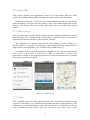
2.4. Outdoor Location
Some location methods that have been reviewed in the previous section are applicable
for indoor location and outdoor location. In this section, the different technologies for
location in outdoor environments will be reviewed.
The most important technologies and the most commonly used are Global
Positioning System and the Mobile-Network Location.
2.4.1. Global Positioning System
The Global Positioning System (GPS) is able to calculate the position of a device in the
terrestrial surface using at least three satellites. Nowadays, there is just one group of
satellites that can be used for this positioning system (called Navigation Satellite
Timing and Ranging (NAVSTAR)). This constellation is composed by twenty-four
active satellites and four already prepared satellites for emergency purposes.
24
There is another constellation of satellites called GLONASS (Global Orbiting
Navigation Satellite System). This Russian system is not as implemented as the GPS
and just few devices can use it for location purposes.
Additionally, the European Space Agency (ESA) is developing another constellation
called Galileo, which actually is in testing stage. It is compatible with GPS that will be
free for basic location services with an error fewer that 5 meters.
The GPS system can be split in three different areas: Space area, Control area and
user area. The first area is the one which contains the system satellites, the control area
is composed of the terrestrial infrastructures that control the satellites, and the last one,
are the different devices and software that processes the signals.
This system is able to locate a device using triangulations. It calculate the distance
of a device from three of more satellites with a well know position in the orbit. These
satellites are perfectly synchronized with an atomic clock, which ensures the smaller
possible error in the measures. The device also has to be able to process the different
signals from the satellites with the description of the satellite and notice it to the
network. The location process is done measuring the time of arrival from the satellite to
the device. This process is similar to the TDOA explained in the previous sections.
The GPS system has also inconvenient aspects, the precision in outdoor
environment is accurate but when the environment is close as in a big city with
buildings this accurate become less reliable. The device and the satellites must be in line
of sight and in other cases a delay in the reception of the signal will be observed. In
order to solve this problem, the Differential GPS (DGPS) is used in the metropolitan
areas. This system uses the satellite signals and some information from the stations.
This system is used in the Assisted GPS (AGPS) and it will be reviewed further in this
section [11] [12].
Figure 2.4.1 – GPS
25
2.4.2. Mobile Network-based location
All the location method described in previous sections of this document such as CGI,
AOA, TOA, TDOA and more can be use for mobile network location purposes. Some
of them are fully compatibles and others just need some slightly modifications in the
network or some additional functionality in the terminal device.
The information for location purposes is in the cell with the GSM technology, since
it is needed to establish communication with other device (the system needs to know in
which cell is the terminal). This information could not be accessed from outside the
network but nowadays it has been redesign in other to be able to access that
information. In the Universal Mobile Telecommunications System (UMTS) location
information can be accessed from inside and outside of the network.
Mobile companies use some combination of the location technologies in order to
provide different ways of location. The most popular used technologies are the
followings:
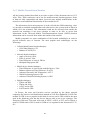
• Cellular Identification-based techniques:
o Cell Global Identity, CGI.
o Enhanced Cell-ID, TA.
• Network-based techniques:
o Angle of Arrival, AOA.
o Time of Arrival, TOA.
o Time Difference of Arrival, TDOA.
o Multipath Fingerprint, MF.
• Mobile device-based techniques:
o Time Difference of Arrival with modified device, TOA.
o Enhanced Observed Time Difference, E-OTD.
o Advanced Forward Link Trilateration, A-FLT.
o Global Positioning System, GPS.
o Advanced Global Positioning System, A-GPS
• Hybrid techniques:
o TDOA and RSS.
o TDOA and AOA.
o A-FLT and A-GPS.
o E-OTD and A-GPS.
In Europe, the most used location services provided by the phone network
companies are based in cell identification methods as Cell-ID or Enhanced Cell-ID. The
method E-OTD is not so popular in this kind of services and A-GPS could be the most
used in the following years but the devices that are able to use it are expensive. The
European GSM uses TOA and AOA and in EEUU A-GPS, A-FLT and O-TDOA is
used for CDMA and A-GPS is used for GSM as it is regulated in the document FCC E911.
26
How those technologies are used and implemented nowadays in our networks will
be explained. For this purpose, those technologies will be split into cell identificationbased, network-based and mobile device-based methods [11] [12].
Cell Identification-based
This method is actually one of the most used for the mobile phone-network companies.
In order to improve the services an improved method has been developed and it is called
Enhanced Cell-ID. This method is able to locate any kind of devices over all the mobile
networks as GSM, GPRS, UMTS and CDMA.
Enhanced Cell ID provides more accuracy over Cell ID using Radio Frequency
parameters such as Timing Advance (TA) in order to know the position within the cellsector. In GSM, the timing advance corresponds to an approximation in time that the
signal needs to go from the device to the BTS of the cell which the phone is connected
at that time [7] [9].
Network-based
In this section, two different technologies can be found: TDOA and Multipath
Fingerprint (MF).
• TDOA: TOA is a very costly approach to implement because it needs Location
Measuring Units called LMUs, in the other hand, TDOA works in the same way
as it has been explained in time-based section, but taking into account that in
urban areas it can have multipath and sometime four BTS are needed because of
its reflexions. It rural areas TDOA can be combines with AOA to improve the
accuracy [12] [9].
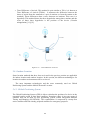
• Multipath Fingerprint (MF): This method is used mainly in urban areas since it is
focused on preventing those reflexions than can be caused by the building in a big
city. In order to identify these reflexions the stations have to send test units to the
different received signals from the terminal and when a multipath is detected save
it into the database. Then next time it receives a signal the station could check in
the database. The accuracy of this method resides in the number of multipath
stored in the database [11].
Figure 2.4.2.1. – Multipath signals
27
Mobile device-based
Finally in this section, some enhanced method of the previous ones will be reviewed, EOTD, A-FLT, E-FLT and A-GPS.
First of all, the Enhanced Observed Time Difference (E-OTD), works over GSM
and GPRS and it is a new technology for the network and also for the terminal devices.
It works similar to the TDOA,
There are two different procedures in this method, the first one uses hyperbolic
triangulation, the terminal observers the time difference of arrival from two different
base stations, those observation are known as Observed Time Difference (OTD). The
measured OTD of a base station defines a hyperbolic locus. The same process is
repeated with a second base station and the intersection of the two hyperbolic locus
gives an estimate of the location of the mobile. The more measures are done with
different base stations the more accurate is this approach.
The second procedure, which uses circular triangulation needs location
measurement units (LMUs). The number of LMUs involved in the location process
determines the precession of it. The common approach is to use one LMU each one or
two stations. These receivers and the terminals with E-OTD software are the ones that
measure the signals from two or more different stations.
The network can assist the position calculation if the terminal measures the signal
OTD and the network send to the terminal the rest of the information as the BTS. Or in
other way, the terminal can assist the network by sending the OTD to the network,
which is the one that calculate the position.
Another mobile device-based method is Advanced Forward Link Trilateration (AFLT). This technique is used in CDMA networks and it is similar to the TDOA. A-FLT
consists of measuring the delay of a signal sent to two different BTS and compares this
delay with the measure of another pair of BTS. This technique locates a device using
three BTSs. Enhanced Forward Link Trilateration (E-FLT) works in a similar way than
A-FLT but it needs some modification in the network and in the BTS.
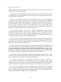
Finally, the A-GPS is a technology that has been developed in order to get a faster
and more accuracy position than the conventional GPS and also requires less processing
power and therefore, save battery life on the mobile devices.
The A-GPS is composed by a terminal device with GPS receiver, a A-GPS server
with a reference GPS receiver or a differential GPS service (DGPS) and a mobile
network structure. The reference GPS receivers obtain information of the navigation
and differential correction data for the GPS satellites, which are in the coverage area.
Once the server obtains all these information, it provides some to the terminal
devices, mainly a table with the position of all the satellites which can contact with that
device. All those data messages are small packages of 50 bytes size and contain all the
necessary information to complete the received GPS data.
28
The location server can also access to a database that contains information of the
geographical area in order to provide the altitude of the devices position.
A-GPS can be used in synchronous and asynchronous networks so it can be used in
GSM, GPRS, UMTS and CDMA [11] [12].
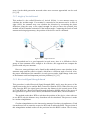
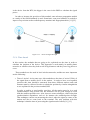
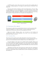
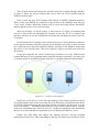
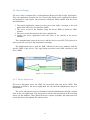
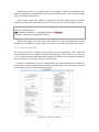
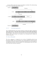
Figure 2.4.2.2. – A-GPS
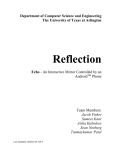
Following the image above all the necessary steps to locate a device using A-GPS
will be explained briefly.
1. The device sends a location request.
2. The location server processes the received Cell-ID obtained from the BS in which
the device is located. Then, the location server processes that information to
obtain the near satellites to that location and sends the list of satellite to the
device.
3. The GPS information is combined with the BS information and they are sent to
the location server.
4. Finally, the coordinates are transmitted back to the device .
2.5. Indoor Location
All the technologies that have been reviewed in the previous section provide the final
user location services with good accuracy. In some cases, when the user is inside a
building or in more close environments, the accuracy of those technologies will be
affected and it will not provide a good service to the user. In this section, some
technologies suitable for indoor location will be studied.
29
IEEE 802.11
Nowadays, the Wireless Local Area Networks (WLAN) has become so popular and
they can be found in almost every place as hotels, shops, airports, and in some many
places in order to allow the users to have broadband access. This technology provides us
another way of location for indoor environments.
There are different kinds of WLAN and IEEE 802.11 is the set of standards that all
of them must follow. The original version of the standard was released in 1997 and it
has been improved in order to provide a faster and a easier way of connection. Actually,
the most advanced is called IEEE 802.11n providing a data rate from 54Mbit/s to
600Mbit/s. Also the versions IEEE802.11ac and 802.11ad are under development.
The location using WLAN for indoor environments can be done using different
approaches. The simplest one is based on the access point (AP) near the device. This
cannot be used for 3D location because of its poor accuracy, this fact makes hard to
know in which floor in side a building a device is located.
The devices with Neural Cellular Positioning System (NCPS) measure the signal
power from the AP and if that power is lower that a limit, it changes to another AP. In
this process, the device sends to the positioning system the power of the signal and the
AP identification [12].
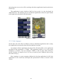
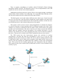
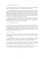
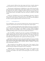
RFID
The Radio Frequency Identification (RFID) is used to identify an object or person that
is in a certain distance by reading its ID included in a tag. Tags, readers and control
systems compose the RFID systems. The objects or persons are the ones that carry the
tags with the ID information located in those small chips. The readers are equipped with
an antenna that activated the tags and is able to read its information and sometimes also
write in the tags.
Those RFID tags can be distinguish into two types, passives and active tags. The
passive tags do not have own power source to be activated and so, the power source of
the reader is need to read the tags. Those tags are small chips which contains basic
information (Object ID) that it is send to the reader when the reader send a power signal
to the chip. Passive tags are cheap and small since they do not have power source but
the reading range is small, until couple of meters. The bar codes are being substituted by
this kind of cheap RFID tags.
On the other hand, the active tags have their own power source inside the tags that
allow these tags to send information to the readers. The reading range is bigger that the
one of the passive tags (dozens of meters) and also its memory and cost is bigger. Those
tags are used mainly to identify mobile objects.
For location purposes the most used tags are the active tags because of its reading
range, but that range also depends on the environment. Also some other aspects must be
taken into account as the reading rate (tags per second), the battery life or the size of the
tag.
30
An UHF tag with a correct reader can provide very good results as reading range of
100 meters, a reading frequency of 100 tags per second, a memory of 32kb and a 5 year
battery life.
The strong point of these technology is that is becoming cheap in a fast way. They
are small and easy to use for so many purposes. In case of the location, a device could
read those RFID tags and send its information to a location centre that will know a
approximation location of that device. RFID are used also in Android devices since they
have tags able to change the behaviour of the phone just reading them [12].
Figure 2.5 – RFID transmision
2.6. Geolocation API in Android
The location of a mobile device in Android can be done in several ways such as GPS,
cell tower triangulation or via Wi-Fi networks. In order to manage and obtain the
Android device location, the android.location package has been used.
Inside this package different classes can be found as the Location, the
LocationListener class or LocationManager class which are the most important to
perform the location of a device.
2.6.1. Location Class
This class provides a structure where all the information of a location point will be
stored. An object will keep all the useful information of a location point and also it will
provide some useful methods such as the distance between two different points.
The main attributes of this object are the latitude and the longitude which are the
two needed coordinates to determine the position of a point in the map. These attributes
can be accessed by the method getLatitude() and getLongitude(). Also the attribute
provider can be useful to know where the location information comes from and it can be
accessed by the method getProvider().
Additionally, the distance that exists between two points in the map is important to
be known. This object provide us the method distanceTo() which give us the distance
between the location that calls the method and the location introduced by parameter in
the method [13].
31
2.6.2. LocationManager Class
This class provide a full control over all the location features GPS, cellular location and
Wi-Fi by providing status of the device and methods to obtain the location.
The method isProviderEnabled() is used to know if a provider is enable in a specific
moment and can be used to obtain the location. Once the provider has been check if is
enable the LocationManager request for the location using an specific provider by
calling the method requestLocationUpdates() which mainly receive a provider and a
LocationListener that will be reviewed in the next section and received the location of
the device. The LocationManager also has to close the update when it not necessary to
receive any more by calling the method removeUpdates().
Another important function of this object is the last know location process. Since the
LocationManager is in charge of controlling the location, it is the one that knows the
last location on each moment and in case of the request for new location fails the
method getLastKnownLocation() can be accessed [13] [6].
2.6.3. LocationListener Class
The location listener is used to receive the notification from the LocationManager.
When a new update arrives, here is where the location is received and saved in a
LocationResult. The main function of this class is to obtain the location when the
locationManager asks for updates. The method that receives the locations is called
onLocationChanged() and received as a parameter a Location object which is where the
received location will be stored. [13] [15]
2.6.4. Wi-Fi location
In order to provide a better location on indoors, a Wi-Fi based location has been used.
For this purpose the package android.net.wifi provides us two useful classes, WifiInfo
and WifiManager.
The WifiManager control the Wi-Fi status and provides all the necessary
information such as the enable status using the method isWifiEnabled(). Also, it
provides information about Wi-Fi connections that can be stored in a WifiInfo.
This object can realize Wi-Fi scans to show the available connections around the
device using the method startScan(). To realize the scan and the method
getScanResults() to obtain a list of connection that are in the range of the device.
Each of those connections can be stored in an object WifiInfo in order to access
some useful information such as BSSID that identifies a Wi-Fi connection [14].
32
2.7. SQLite Database API
SQLite is a light database embedded into Android OS. This database is very useful
since it is a light databases and consumes low memory while running which is
important in mobile devices with restricted memory.
This database does not require any setup or administration, it is managed
automatically by the operating system and it only requires defining the SQL statements
for creating and updating the tables. Every operation in the database results in an access
to a file, so it is recommended to perform every operation to the database
asynchronously.
In order to use this database some packages should be imported as the
android.database.sqlite, which contains the specific classes for creating and using the d
SQLite database. The SQLiteOpenHelper class is in charge of creating and updating the
database and the SQLiteDatabase in the one that provide the methods to perform every
action to manipulate the database [16].
2.7.1. SQLiteOpenHelper Class
This is the base class for creating an SQLite database. Here is where all the tables and
update rules are defined. In the constructor the method super is called with a name and
the version of the database that want to be created.
Also in this class is important to create more methods as onCreate(), which creates
the tables by executing a SQL statement. In those statements all tables will be defined
with the specific fields, types, primary keys and name of each table.
The method onUpgrade() defines the rules that must be executed when the version
of the database is increased. The tables can be dropped in order to create new ones with
different schema or just add some more rules or changes.
These methods receive as parameter objects of the class, which will be, explain in
the following subsection SQLiteDatabase. Also, the object SQLiteDatabase can be
access the calling the methods getReadableDatabase() or getWriteableDatabase()
provided by SQLiteDatabase depending if a read or a write is needed [17].
2.7.2. SQLiteDatabase Class
This class is basic for working with the SQL database. It provides all the needed
methods to open, query, update and close the database. The methods provided by this
class are called insert(), update() and delete(). Also, the methods close() and open() that
allows us to start/stop reading or writing from the database are provided by this class
and finally the method execSQL() that allows to execute all the SQL statements.
One very useful object that is used while working with SQLite databases is
ContentValues. This object allows defining key/values. The key is the identifier field of
a table and the value is the content of that specific field. This object is commonly used
to insert and update tables in the database.
33
The queries can be created using the method rawQuery() which receives a string
with SQL statements to execute. In order to keep the result of that query the object
Cursor is used. A cursor works as a list of result and points to one of them in this way
all the results can be buffered and it is not need to store into memory. The method
getCount() return the number of results and it can be iterated with the method
moveToNext().
The most simple use of the cursor is to move to the first position with the method
moveToFirst() and then check if it is the last result with isAfterLast(), if it is not the
method moveToNext() is called after getting the information of that result.
If the result has several columns, they can be accessed using getString(column
index) where column index in the number of the column that is be accessed. After all,
the cursor must be close using close() [17].
2.8. Package Management API
The APPs in the Android devices are installed as packages where all the information
about the APPs can be found. In this section, the different APIs used in order to obtain
that information and manage those packages is explained.
For this purpose, different packages can be distinguished. In one side, the classes
that control the running processes in the device and, in the other side, the classes that
manage the installed APPs in the device.
The class android.app.ActivityManager provides us access memory information
such as the running processes, also the ActiviyManager allows to manage the memory.
An interesting method that provides the running processes in the device is
getRunningAppProcesses() which returns a list of processes. That list is composed of
objects called RunningAppProcessInfo which contain useful information such as the
processName and the PID (Process identifier).
The classes that manage the installed packages in the device are
android.content.pm.PackageManager and android.content.pm.PackageInfo. The
PackageManager is quite similar to the ActivityManager but it provides information
about all the packages installed and not just the running processes. This class allow us
to obtain information from the packages such as permissions using the method
getInstalledPackages() the attribute of the method indicates what information about the
packages is required, for instance, in case of permission it should be
PackageManager.GET_PERMISSIONS. This method returns a list of PackageInfo
objects which are also similar to the RunningAppProcessInfo object and it contains the
name of the APP but in this case the permissions of the APP can be found in this object.
Using those classes it should be easy to obtain, for instance, all the permissions of
the running processes in the Android device. In following sections the importance of the
permissions in the Android OS will be explained [18].
34
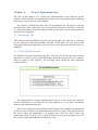
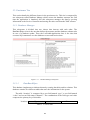
2.9. Android Permissions
This section describes how the permissions are used in Android applications for security
features. The main point of the security based in permission is that no application has,
by default, permission to perform any operation that would impact other applications,
the operating system or the user by default. Some examples of this operation are reading
user data (Contact list or mails), accessing to other applications data or accessing the
network features.
In Android OS, application are sandboxed from each other, and this makes that the
application have to share resources among them. The permissions are different in each
application, This mechanism restricts the application of doing any operation unless the
specific permissions has been granted.
These permissions required are shown during the installation. The user must read
the list of permissions that the application requires. The user must read the list of
permissions and if the permissions are accepted. In case the user accept or deny the
permission list, the whole list will be apply or refuse but the user cannot choose just
some permissions from the list and it will be apply to the application permanently. This
means that if the list is accepted the permissions of the application cannot be deny
unless the application is uninstalled from the device. Android has no mechanism for
adding permission in runtime since it would complicate the user experience while
running the application. [20]
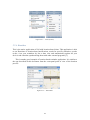
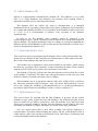
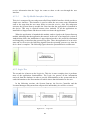
Figure 2.9.1. – Android Permissions List
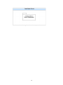
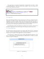
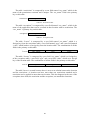
In order to add permissions to the application, the permissions must be included in
the application AndroidManifest.xml using the tag <uses-permission>. For instance, an
application that requires Internet access must include the following line in the manifest:
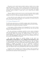
35
Figure 2.9.2. – Manifest example
During the application install time, the package installer grants the permissions
requested by the applications just if the user checks and agree the permissions list. No
more checks are done during the running time. If any permissions have been granted the
application could use that feature as it desires or in the other case, if the permissions
have been denied, the application have no way to performance the requested operation.
In both cases, the user won’t be noticed. [20]
The permissions are constantly changing. This means that the developer must be
aware and launch updated versions of the application with the new permissions to
ensure that the application is running well.
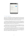
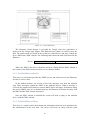
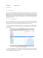
2.10. Google APP Engine
Google APP Engine is a cloud system where the web applications can be stored and
run. This cloud system is different from others cloud systems, it is neither IaaS
(Infrastructure-as-a-Service) nor SaaS (Software-as-a-Service). It is something inbetween called PaaS (Platform-as-a-Service).
The motivation of this choice is the robust, scalable and the easy application
deployment. GAE provides an API to develop the web applications using Java
technologies. This platform is scalable. As the number of request to the web application
increases, the App Engine automatically allocates more resources for the web
application in order to handle those requests. [30]
Other good point of using Google App Engine is that web application can be built in
using standard Java Technologies, the App Engine used Java Servlets for the web
application. The easy web application deployment is another advantage to this
technology since Google manages the application and the user does not have to worry
about managing resources.
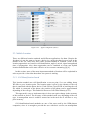
Finally, Google App Engine provides scalable databases using the Datastores.
These Datastores use a High Replication Datastore (HRD) which uses the Paxos
algorithm to replicate data across multiple data centres.
The data is written in the Datastore as entities and each entity has a key that
indentifies the object, then more attributes can be added to the entity. These Datastore
can also execute SQL queries. Also, the Datastore can be managed and motorized from
the Google App Engine web application using a friendly user interface providing the
user a friendly view of the database structure. The user can also realized SQL queries.
Google App Engine also provides a XMPP service to communicate with other
applications over this protocol. This service provides a fast messaging protocol which
can be used to interchange information among different applications. Those messages
36
are encrypted using SSL/TLS, which provides a secure communication between the
clients and the server.
Finally, the easy deployment, the scalability of the system and the compatibility
with different systems and languages make the Google App Engine a good reasonable
technology to implement in our system.
37
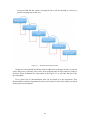
Chapter 3.
Project Analysis
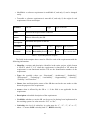
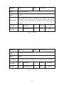
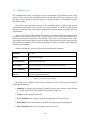
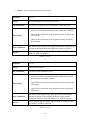
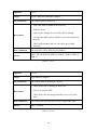
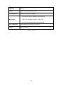
The purpose of this chapter is to describe the project by specifying its requirements.
There are different kinds of requirements. First of all, the functional requirements define
some functions that the program must accomplish. Then, the non-functional
requirements (also known as quality requirement), which impose constrains on the
design and implementation (such as performance requirements).
After defining those requirements, some tests are needed in order to ensure a correct
performance and that every requirements has been implemented in a proper way into the
system.
Finally, a development methodology and lifecycle, which will be followed, is going
to be described by providing and explaining all the project stages in order to schedule
and develop a good quality product.
3.1. System Requirements
This section will provide information about the Software Requirements of this project,
including their description, functionalities and more important characteristics. These
requirements will be divided between Functional and Non-Functional Requirements.
During the project analysis phase one of the most critical steps are the system
requirements specification. In order to archive the best results in this phase, the IEEE
recommended practices have been followed [26]. This document provides us the basic
issues that the system requirements shall address such as functionality, external
interfaces, performance, attributes and design constrains.
Also, according this standard in order to archive a good system requirement
specification those system requirements should have the following characteristics:
• Correct: a software requirement is correct if, and only if, every requirement meets
a functionality of the program.
• Unambiguous: a software requirement is unambiguous if, and only if, has only
one interpretation.
• Complete: a software requirement is complete if, and only if, includes all
significant requirements.
• Consistent: a software requirement is consistent if, and only if, agrees with the
rest of the requirements and it does not make conflicts.
• Ranked for importance and/or stability: a software requirement is ranked if, and
only if, each requirement in it has an mark of the importance/stability.
• Verifiable: a software requirement is verifiable if, and only if, there is any process
to check that the requirement has been implemented.
38
• Modifiable: a software requirement is modifiable if, and only if, can be changed
easily.
• Traceable: a software requirement is traceable if, and only if, the origin of each
requirement if clear and unique.
Identifier
YR-XX
Type
Name
Short and descriptive name of the SR.
Actors
What is affected by the SR.
Description
A detailed description of the SR.
Verifiable
Yes/No Criticality
Essential
Yes/No Desirability Level 1 to 5
1 to 5
Type of the SR.
Purpose The objective
State
The current state
Table 1 – System Requirements Template
The fields in the template above must be filled for each of the requirements with the
following information.
• Identifier: a unique and descriptive identifier in the entire project, which format
is YR-XX, where Y is F when the requirement is functional or NF when the
requirement is non-functional and the XX are the identification number of the
requirement.
• Type: the possible values are: “Functional”, “Architecture”, “Scalability”,
“Performance”, “Technology”, “Availability”, “Supportability”, “Security”,
“Usability” and “Interface”.
• Name: short and descriptive names of the SR that can let the user make an idea
about the purpose of the requirement.
• Actors: what is affected by the SR or “-“ if the field is not applicable for the
requirement.
• Description: a detailed description of the requirement.
• Verifiable: whether or not the SR can be proved as having been implemented in
the resulting system. Its value must be “Yes” or “No”.
• Criticality: the level of criticality: its value must be “1”, “2”, “3”, “4” or “5”,
where “1” means LOW criticality and “5”, HIGH criticality.
39
• Purpose: the main objective of the SR.
• Essential: whether or not the SR is essential for the resulting system to work
properly.
• Desirability level: its value must be “1”, “2”, “3”, “4” or “5”, where “1” means
LOW desirability and “5”, HIGH desirability. All essential requirements have a
“5” value.
• State: the current state of the SR: its value must be “Stable”, “Unstable” or
“Suspending”, where “Stable” means that the SR is not likely to change,
“Unstable” means that the SR may be dependent on feedback from the testing or
the user, and “Suspending” means that the SR may be pending resources which
are becoming available.
3.1.1. Functional Requirements
Identifier
FR-01
Type
Functional
Name
Restrictions Mechanism
Actors
System
Description
The system must be able to restrict the execution of APPs based in
the location mechanism such as the Wi-Fi and the location (GPS and
Network).
Verifiable
Yes
Criticality
5
Purpose
Essential
Yes
Desirability Level
5
State
Table 2 – FR-01
40
Capability
Stable
Identifier
FR-02
Type
Functional
Name
Rules Syntax
Actors
System
Description
The Rules must be composed by the following field:
- Location: Value to locate the device and its max distance.
- Restrictions: The permissions that must be restricted.
- Exceptions: The APPs that can still run in the device.
Verifiable
Yes
Criticality
5
Purpose
Essential
Yes
Desirability Level
5
State
Capability
Stable
Table 3 – FR-02
Identifier
FR-03
Type
Functional
Name
Rules restriction
Actors
System
Description
The restriction mechanisms shall be based on a rule system, being
each rule defined by an administrator. The rules will be composed by
locations, restrictions and exceptions. The administrator is able to
associate restrictions to locations and the exceptions will be APPs
which will not be affected by those restrictions on that location.
Verifiable
Yes
Criticality
5
Purpose
Essential
Yes
Desirability Level
5
State
Table 4 – FR-03
41
Capability
Stable
Identifier
FR-04
Type
Usability
Name
Basic Exceptions
Actors
System
Description
The system must be able to add some basic exceptions that cannot be
restricted in other to protect the basic functionality of the device.
Input Systems, System UI, Phone and Messaging Services, Settings,
Launcher. The project application will be included in the exceptions
in order to prevent it to be restricted.
Verifiable
Yes
Criticality
4
Purpose
Essential
Yes
Desirability Level
5
State
Constraint
Stable
Table 5 – FR-04
Identifier
FR-05
Type
Functional
Name
Scan and obtain Wi-Fi identifier
Actors
System
Description
The system must be able to scan the Wi-Fi stations near the device
and obtain the BSSID of each of them.
Verifiable
Yes
Criticality
5
Purpose
Essential
Yes
Desirability Level
5
State
Table 6 – FR-05
42
Capability
Stable
Identifier
FR-06
Type
Functional
Name
Obtain GPS Location
Actors
System
Description
The system must be able to obtain the location of the device using the
GPS technology.
Verifiable
Yes
Criticality
5
Purpose
Essential
Yes
Desirability Level
5
State
Capability
Stable
Table 7 – FR-06
Identifier
FR-07
Type
Functional
Name
Obtain Network Location
Actors
System
Description
The system must be able to obtain the location of the device using the
mobile Network.
Verifiable
Yes
Criticality
5
Purpose
Essential
Yes
Desirability Level
5
State
Table 8 – FR-07
43
Capability
Stable
Identifier
FR-08
Type
Functional
Name
Obtain Last Known Location
Actors
System
Description
The system must be able to obtain the last known location of the
device in case the other mechanism fail.
Verifiable
Yes
Criticality
5
Purpose
Essential
Yes
Desirability Level
5
State
Capability
Stable
Table 9 – FR-08
Identifier
FR-09
Type
Functional
Name
Location Distance
Actors
System
Description
The system must be able to measure the distance between two
different location in order to ensure that the device is/is not in a
restricted location.
Verifiable
Yes
Criticality
5
Purpose
Essential
Yes
Desirability Level
5
State
Table 10 – FR-09
44
Capability
Stable
Identifier
FR-10
Type
Functional
Name
Obtain running process
Actors
System
Description
The system must be able to list all the running processes in the
device.
Verifiable
Yes
Criticality
5
Purpose
Essential
Yes
Desirability Level
5
State
Capability
Stable
Table 11 – FR-10
Identifier
FR-11
Type
Functional
Name
Obtain installed APPs
Actors
System
Description
The system must be able to list all the installed APPs in the device.
Verifiable
Yes
Criticality
5
Purpose
Essential
Yes
Desirability Level
5
State
Table 12 – FR-11
45
Capability
Stable
Identifier
FR-12
Type
Functional
Name
Get APP permissions
Actors
System
Description
The system must be able to access the required permissions of every
APP in the device.
Verifiable
Yes
Criticality
5
Purpose
Essential
Yes
Desirability Level
5
State
Capability
Stable
Table 13 – FR-12
Identifier
FR-13
Type
Functional
Name
Read Rules File
Actors
System
Description
The system must be able to access the device assets. The file with the
rules will be located in the assets. This file will be read to add/modify
rules in the system
Verifiable
Yes
Criticality
4
Purpose
Essential
Yes
Desirability Level
4
State
Table 14 – FR-13
46
Capability
Stable
Identifier
FR-14
Type
Maintainability
Name
Automatic Updated
Actors
System
Description
The system must be able to download update files with rules in order
to keep the rules up to date.
Verifiable
Yes
Criticality
3
Purpose
Essential
Yes
Desirability Level
4
State
Capability
Unstable
Table 15 – FR-14
Identifier
FR-15
Type
Security
Name
APP Heartbeat
Actors
System
Description
The system must be able to sent a check message to a server in other
to ensure that the APP is running in the device.
Verifiable
Yes
Criticality
3
Purpose
Essential
Yes
Desirability Level
4
State
Table 16 – FR-15
47
Capability
Unstable
3.1.2. Non Functional Requirements
Identifier
NFR-01
Type
Performance
Name
Locate and check location every 30 seconds
Actors
System
Description
The system must request the device location every 30 seconds and
check if it is in a restricted area.
Verifiable
Yes
Criticality
5
Purpose
Essential
Yes
Desirability Level
5
State
Constraint
Stable
Table 17 – NFR-01
Identifier
NFR-02
Type
Functional
Name
Store Rules
Actors
System
Description
The system must be able to have access and store all the rules in the
database. This requirement includes all the necessary actions to
manage the database such as add rules, find rules or apply filters.
Verifiable
Yes
Criticality
5
Purpose
Essential
Yes
Desirability Level
5
State
Table 18 – NFR-02
48
Capability
Stable
Identifier
NFR-03
Type
Scalability
Name
Scalable Database
Actors
System
Description
The system database must be able to manage a great quantity of data
in order to keep all the restrictions. Each device must be able to store
10,000 rules in the database.
Verifiable
Yes
Criticality
4
Purpose
Essential
Yes
Desirability Level
4
State
Constraint
Stable
Table 19 – NFR-03
Identifier
NFR-04
Type
Supportability
Name
Not Device Dependency
Actors
System
Description
The system must run in as much different devices as possible.
Verifiable
Yes
Criticality
3
Purpose
Essential
Yes
Desirability Level
4
State
Table 20 – NFR-04
49
Constraint
Stable
Identifier
NFR-05
Type
Usability
Name
Transparent to the user
Actors
System
Description
The system must be transparent to the user. The user of the phone
does not have to known that the APP is running (Except when some
APP is restricted).
Verifiable
Yes
Criticality
3
Purpose
Essential
Yes
Desirability Level
4
State
Constraint
Stable
Table 21 – NFR-05
Identifier
NFR-06
Type
Availability
Name
System availability
Actors
System
Description
The system must be available all the time in order to ensure a correct
performance
Verifiable
Yes
Criticality
5
Purpose
Essential
Yes
Desirability Level
5
State
Table 22 – NFR-06
50
Constraint
Stable
Identifier
NFR-07
Type
Performance
Name
Location Deadlines
Actors
System
Description
The system must have a deadline that changes the location
mechanism if one o them are slow. First try to locate by GPS and if it
is slow locate with Network and if both fail get the last known
position.
Verifiable
Yes
Criticality
3
Purpose
Essential
Yes
Desirability Level
5
State
Constraint
Stable
Table 23 – NFR-07
Identifier
NFR-08
Type
Performance
Name
Check APPs each 1.5 seconds
Actors
System
Description
The system must check if the APPs are restricted each 1.5 seconds.
Verifiable
Yes
Criticality
3
Purpose
Essential
Yes
Desirability Level
3
State
Table 24 – NFR-08
51
Constraint
Stable
Identifier
NFR-09
Type
Usability
Name
APP cannot be stopped
Actors
System
Description
The system will inform the server when the APP has been stopped.
Verifiable
Yes
Criticality
2
Purpose
Essential
No
Desirability Level
2
State
Constraint
Stable
Table 25 – NFR-09
Identifier
NFR-10
Type
Security
Name
Secure connection
Actors
System
Description
The system must connect with the server through a secure channel
(HTTPS) in order to ensure security while downloading the rules.
Verifiable
Yes
Criticality
3
Purpose
Essential
Yes
Desirability Level
5
State
Table 26 – NFR-10
52
Constraint
Stable
Identifier
NFR-11
Type
Usability
Name
Start APP when device start
Actors
System
Description
The system must start running when the device starts.
Verifiable
Yes
Criticality
3
Purpose
Essential
Yes
Desirability Level
5
State
Table 27 – NFR-11
53
Constraint
Stable
3.2. Validation tests
The validation tests allow verifying the correct performance of the different parts of the
system. These test provide some input into the system, then, the system responses with
an output. If the output is not the expected, it means that there is something wrong in
the tested module.
One of the most important aspects in this validation phase is that all the system
requirements should be covered. In this case, the validation of all the required system
functions is ensured. This will ensure a high quality software that meets all the specified
requirements.
All the tests will be defined on this document, providing the different step that must
be taken to execute the test correctly. In some cases, the test can be successful for two
different modules but when they work together may exists some problems. This is the
reason that some test just affect a specific module in the project but some other tests can
affect different modules of the project, ensuring the correct performance when different
modules work together.
All the tests that are specified follow the following table template:
Identifier
VT-XX
Target
Specific test target.
Pre-Conditions
Input values to the test.
Description
Brief description of the step that must be followed.
Post-Conditions
Expected results.
Source
System requirements tested.
Table 28 – Validation Test Template
The fields in the template above must be filled for each verification test with the
following information:
• Identifier: a unique and descriptive identifier in the entire project, which format
is VT-XX, where XX in the identification number of the test.
• Target: what is going to be tested.
• Pre-Conditions: the required values that are going to be needed in test.
• Description: a brief description of the different steps to perform during test.
• Post-Conditions: the expected output results of the test.
54
• Source: system requirement source for the test.
Identifier
VT-01
Target
Scan and obtain Wi-Fi identifier process.
Pre-Conditions
A test Wi-Fi stations will be required to execute this test.
- Add a rule with location based in the testing Wi-Fi BSSID.
Description
- Check if the restrictions and exceptions execute outside the
Wi-Fi range.
- Check if the restrictions and exceptions execute inside the
Wi-Fi range.
Post-Conditions
All APPs execute outside the range but inside the range just the
exceptions and non-restricted APPs are be able to execute.
Source
FR-01, FR-02, FR-03, FR-05, NFR-01, NFR-02, NFR-04,
NFR-05, NFR-06, NFR-08
Table 29 – VT-01
Identifier
VT-02
Target
Obtain GPS Location
Pre-Conditions
The device GPS should be active
- Add a rule with location based in the testing location GPS
point and the maximum distance.
Description
- Check if the restrictions and exceptions execute outside the
GPS range.
- Check if the restrictions and exceptions execute inside the
GPS range.
Post-Conditions
All APPs execute outside the range given by the maximum
distance from the GPS point but inside the range just the
exceptions and non-restricted APPs are be able to execute.
Source
FR-01, FR-02, FR-03, FR-06, FR-09, NFR-01, NFR-02, NFR04, NFR-05, NFR-06, NFR-08
Table 30 – VT-02
55
Identifier
VT-03
Target
Obtain Network Location
Pre-Conditions
The device must have signal and the GPS disabled.
- Add a rule with location based in the testing location point
and the maximum distance.
Steps
- Check if the restrictions and exceptions execute outside the
location range.
- Check if the restrictions and exceptions execute inside the
location range.
Post-Conditions
All APPs execute outside the range given by the maximum
distance from the location point but inside the range just the
exceptions and non-restricted APPs are be able to execute.
Source
FR-01, FR-02, FR-03, FR-07, FR-09, NFR-01, NFR-02, NFR04, NFR-05, NFR-06, NFR-08
Table 31 – VT-03
Identifier
VT-04
Target
Obtain Last Known Location
Pre-Conditions
The device must not have signal and the GPS disabled.
- Add a rule with location based in the testing location point
and the maximum distance.
Steps
- Check if the restrictions and exceptions execute outside the
location range.
- Check if the restrictions and exceptions execute inside the
location range.
Post-Conditions
If the last location was in a restricted area the associated rules
are applied, if it was not, the APP can be executed.
Source
FR-01, FR-02, FR-03, FR-67, FR-07, FR-08, FR-09, NFR-01,
NFR-02, NFR-04, NFR-05, NFR-06, NFR-07, NFR-08
Table 32 – VT-04
56
Identifier
VT-05
Target
Basic exceptions
Pre-Conditions
The device must be in a restricted area.
- Add a rule with a specific location and restricting
permissions of a basic APP such as the Phone should be
added.
Description
- The device must be located inside the range of the rule
location.
- Execute the basic APP (Phone APP in this case) while being
in the restricted location.
Post-Conditions
Source
The system will not restrict the basic services and the device
will work properly using those basic services.
FR-01, FR-02, FR-03, FR-04, FR-10, NFR-01, NFR-02, NFR04, NFR-05, NFR-06, NFR-08
Table 33 – VT-05
57
Identifier
VT-06
Target
Add Rules from File and Execute.
Pre-Conditions
The rules must be written in the XML file with the specific
syntax.
- Create an XML file with the correct structure indicating to
add a new rule.
- Send the file to the device assets folder.
- The device must be located inside the range of the rule
location.
Description
-
Check if the device can execute the restrictions and the
exceptions in the specified location.
- Move the device to other location.
- Check if the rules still apply trying to execute restricted
APPs.
Post-Conditions
The system must be able to execute the specified exceptions
and will not execute the restricted APPs in the location.
Source
FR-01, FR-02, FR-03, FR-04, FR-05, FR-06, FR-07, FR-08,
FR-09, FR-10, FR-11, FR-12, FR-13, NFR-01, NFR-02, NFR03, NFR-04, NFR-05, NFR-06, NFR-07, NFR-08, NFR-10
Table 34 – VT-06
58
Identifier
VT-07
Target
Service Start and Automatic Updates
Pre-Conditions
The system must be turned off.
- New rules must be added to the rules file.
- Start the device.
- Check in the running services if the APP is running
Description
-
Check if the APP contact with the server to download the
new file.
- Check if the database the new rules have been added
correctly.
Post-Conditions
The new rules will be added to the database.
Source
FR-13, FR-14, NFR-02, NFR-04, NFR-05, NFR-06, NFR-10,
NFR-11
Table 35 – VT-07
Identifier
VT-08
Target
App cannot be stopped
Pre-Conditions
The system must be running in a device.
- Check if the APP is running in the device.
Description
- Force it to stop the APP.
- Check if the APP has stopped and the server receive the
alert.
Post-Conditions
The system will alert that the user have stopped the APP.
Source
FR-15, NFR-09
Table 36 – VT-08
59
Identifier
VT-09
Target
Check if the connection is secure.
Pre-Conditions
The device is doing an Update
- Use a tool to capture packages in the network.
Description
- Capture the updating packages of the APP.
- Check if the information has been encrypted.
Post-Conditions
The communication will be encrypted.
Source
FR-14, NFR-10
Table 37 – VT-09
60
3.3. Traceability Matrix
This section provides the traceability matrix. In this matrix each row represents a
requirement and each column represents a test. When a test covers a requirement is
marked with the symbol X.
X
X
X
X
X
X
X
X
X
X
X
X
X
X
X
X
X
X
X
X
X
X
X
X
X
X
X
X
X
X
X
X
X
X
X
VT-09
VT-06
X
X
X
VT-08
VT-05
X
X
X
VT-07
VT-04
FR-01
FR-02
FR-03
FR-04
FR-05
FR-06
FR-07
FR-08
FR-09
FR-10
FR-11
FR-12
FR-13
FR-14
FR-15
NFR-01
NFR-02
NFR-03
NFR-04
NFR-05
NFR-06
NFR-07
NFR-08
NFR-09
NFR-10
NFR-11
VT-03
SR
VT-02
TEST
VT-01
Every requirement must be validated with at least one test, which means that every
row must have al least one X. This matrix provides a graphical way to have a clear idea
of which requirements are going to be tested by each test.
X
X
X
X
X
X
X
X
X
X
X
X
X
X
X
X
X
X
X
X
X
X
X
X
X
X
X
X
X
X
X
X
X
X
X
X
X
X
X
X
X
X
X
X
X
X
X
Table 38 – Traceability Matrix
61
X
X
X
3.4. Development Methodology
The software development methodology followed in this project corresponds to the
Waterfall model [27], which was described in 1970 by Winston W. Royce but in that
article Royce did not refer to this model as “Waterfall”.
This model provides a simple planning process since one phase cannot be started
until the previous one is finished. This procedure allows us to calculate the time to
finish a specific part of the project and establish concrete deadlines.
In the waterfall model, all the phases must be absolutely correct. Special dedication
should be taken in the requirements and design. A mistake in previous phases has a big
impact in the time, effort and cost of the project since some redesign will be probably
needed in order to fix the errors.
In this project, the software requirements are well described and fix since they are
unchanging and stable requirements. This methodology is a good approach to develop
this kind of stable projects. Also, the waterfall model puts so much emphasis on the
requirements in order to ensure that they are correct and fixes errors at a very low cost
with out having to redesign or implement code.
The development methodology will not be a straight waterfall model since it will
have feedback to previous phases. The main phases of the waterfall model are the
following:
• Requirements: This first step is also the most important, because it is here where
everything that the software must accomplish in the following phases is specified.
A deep analysis will be done in this phase in order to provide the best-defined and
clearest requirements and avoid errors that could be costly in further phases.
• Analysis and Design: This phase is where the software and hardware is defined to
satisfy the requirements mentioned in the previous phase. In the design phase,
some test will be defined to ensure that the requirements are met in further phases
of this project. Important design decisions are taken in this phase and they will
guide and restrict some approaches of the implementation phase.
• Implementation: The implementation phase consist basically in implementing the
design described in the previous phase. The development team consisting of
programmers does this part of the methodology. The output of this phase should
be a first beta of the product that will have some bugs to be tested.
• Verification: Also called testing. The tests defined in the Analysis and Design
phases will be executed in order to ensure that the requirements have been met in
the implementation. This phase is important to ensure a good quality product to
the customer.
• Maintenance and Deployment: All the software requires maintenance in order to
ensure a proper performance by updating the software and fixing some errors that
could not be detected in the verification process. In this project, the maintenance
62
is not provided but the system is deployed and it will be running in a device to
provide a testing beta to the user.
Figure 3.3. – Waterfall development model
In this case, the waterfall model has some feedback on each stage in order to prevent
errors and in case of having some errors, this feedback make it easier and less costly to
fix them. These feedbacks are represented in the Figure 3.3 as red lines that go to the
previous phase.
Every phase has its documentation that can be found over this document. This
documentation contains important decisions and results of each of the phases involved
in this project development.
63
Chapter 4.
Project Design
The purpose of this chapter is to provide a high-level description of how the system has
been designed in order to accomplish the given requirements in the chapter 3. First, a
general description of the system will be given, starting at the side of the administrator
that manages the system and finishing at the end-device application.
Then, the device application will be reviewed showing in a high-level description
the different tiers that compose the application.
This application follows a multitier architecture composed by presentation tier, logic
tier and data tier. The presentation tiers controls all the information that is shown to the
user through the user interface. Then, the logic tier, also known as middle tier, is where
resides the most complex part of the application, it provides services and manages all
the information. Finally, the data tier is where all the information is stored.
4.1. System Design
The aim of this project is to restrict the execution of some applications in different
locations. In order to archive this goal some design decisions have been taken. In this
section those design decisions will be explained.
This system works as a dynamic firewall based on its location. The system restricts
different permissions depending on the device location. This is made using some rules
provided by the administrator.
In order to restrict the applications the system uses some defined rules with a
specific syntax. The rules indicate what permissions are restricted, the location where
those permissions are restricted and if there are any exceptions.
In Android, all the applications require a set of permissions that the user must agree
for allowing the application to be executed in the device. Those permissions indicate
what can be access by the application. The system will use the application permissions
to known which device functionalities are being used by the different applications.
The permissions restricted will be mentioned as restrictions; they are the name of
the functionality that is restricted, for instance, Internet. The restrictions indicate that all
the application that uses a restricted permission is not allowed to be executed in the
device.
Those restrictions will be attached to a location. The system uses location
information to know where the device is located. Depending on the location some
restrictions will be applied. The system allows the administrator to set up restrictions in
different locations.
The rules include exceptions. Those exceptions are attached to a location. These
exceptions allow the administrator to keep some application running even if the
application has some permission restricted in that location. The following figure shows
a graphic example of how a rule is defined in the system.
64
Figure 4.1.1. – Rule Design
This example shows a location using Wi-Fi Mac address that is restricted. The
restrictions on the specific location are Internet and camera permissions so, all the
application installed in the device that uses those permissions cannot be executed but
there are three exceptions provided within the rule and they are the applications
Whatsapp, Facebook and Gmail. Just those three applications that have the restricted
permissions can be executed inside that location.
The system obtains the running processes in the device and analyse its permissions,
using the rules and the location services. Then, the device location is compared to the
rules locations and if there is a match, the system obtains the restrictions and exceptions
in order to stop those processes that are not allowed to run within that location.
Once the rules have been designed and the application restriction process has been
explained, the next step is to explain how the administrator sends the rules to the
different devices.
Three main parts compose the system. The first one is the administrator; this is the
person that sends files to the server. The files follow a XML schema that contains
information for the device application.
The second part is a server which stores the information that the administrator wants
to send to the devices. This server will be accessed from the device application in order
to download the files. Every device has a different file with its identifier number (IMEI)
associated. In this way, the devices access to its file to download its specific
information. The server is implemented over Google App Engine using a Datastore
database which stores those XML files with rules for each device.
The last part is the application that runs in the devices. This application is the main
part of the project; it controls the devices by restricting the applications that can be
65
executed based on its location. These restrictions follow some rules given by the
administrator.
The following figure shows the system architecture graphically.
Figure 4.1.2. – System Architecture
From the point of view of the device user, the application running in the device is
complete transparent. The user just has to start the application the first time and when it
starts everything is done automatically. Then, the application access to the files in case
it needs an update and it stores the information in the database for accessing in the
following executions.
The administrator will manage the device using the XML files, it is required to
follow a simple XML schema that will be explained in the section XML Files and also
in the User Manual can be found a guide for defining rules in those files.
The restrictions are based on permissions, those rules will restrict some application
permissions and every application that requires those permissions is restricted. Also, the
rules have exceptions included where the administrator can add specific application that
can be executed even if they have restricted permissions.
4.2. Application Design
Once the interactions among the three parts of the system have been explained, the
Android application that runs in the devices will be explained into more detail. This
application is the one that performs all the heavy work, updating the rules tables,
controlling the running APPs, getting the APPs permissions, locating the device,
checking the restricted locations, killing the restricted running APPS, etc.
The structure of the application will follow a multitier architecture which is
composed by three tiers: presentation tier, logic tier and data tier. Every tier will run in
the device, just the logic tier will access an external file to update the device.
The following figure shows the software architecture which is composed by
interconnected modules grouped by its functionality.
66
Figure 4.2. – Application Design
The white arrows show interactions among the modules. In this case, the mobile
interface module will be the one in charge of initiating the system the first time that the
application is launched. Also, it provides useful information to the user through the user
interface.
The starting system module starts the service module that controls the device. This
service module uses the location manager to obtain location information and the
database to retrieve and store data.
The location manager module manages all the location systems such as the Wi-Fi,
the GPS and the Network. Also it keeps providing location information to the service
module.
Finally, the Database Manager Module provides and stores the data that the server
module needs such as the rules that the administrator sends to the devices.
4.2.1. Presentation Tier
The Presentation tier is the first tier in the application architecture. This tier manages all
the system interface tasks such as showing information to the user and, in this case,
starting the application service the first time that the app is launched. This tier will
67
receive information that the Logic tier wants to show to the user through the user
interface.
4.2.1.1.
Set-Up Mobile Interface Subsystem
This tier is composed by one subsystem called Setup Mobile Interface which provides a
simple user interface. This interface is used to show the user some setup information
such as the steps that the user must follow to start the service. Also, this subsystem
activates the System Start-up module the first time that the application is launched in
the device. This step is required because since Android 3.0 all the application are
installed in a Stopped state and the user needs to activate the application.
When the application is launched this module sends a signal to the System Start-up
module indicating that the application has started, in the case of an improved version of
Android that allows the installation of apps without interface, this would be eliminated
and changed by an interface that generates log files. Then, the application is in an active
state and it will receive the following signals from the operating system every time the
device boot is complete. The following figure shows the presentation tier architecture.
Figure 4.2.1. – Presentation Tier
4.2.2. Logic Tier
The second tier is known as the Logic tier. This tier is more complex since it performs
most of the application functionalities. The Logic tier process all the information
retrieved from the database in order to provide functionalities to the system and also it
sends information to the Presentation tier which shows that information to the user.
In the following sections, the System Start-up, the Service Controller and the
Location Manager subsystems that compose this intermediary tier will be reviewed.
Figure 4.2.2. – Logic Tier
68
4.2.2.1.
System Start-Up Subsystem
According to the system requirements the application must start running every time that
the device is booted, so this subsystem listens the operating system signal that is sent
when the boot is completed and it starts the Service Controller module.
Starting with Android 3.1 when an application is installed in the device it is in a
stopped state and it will not receive boot complete signals from the operating system.
That means that the application must be launched the first time to change its state to
active and in that way, the application will be able to receive the boot complete signal
form the operating system.
So, the System Start-up subsystem listens to the signal send by the Set-up Mobile
Interface the first time that is launched to start the Service Controller. Once this first
time is done this subsystem will be able to listen the operating system signal boot
complete to start the service with out the user interaction.
4.2.2.2.
Service Controller Subsystem
The Service Controller Subsystem contains the service that is running continuously in
the device. This service is the one that manages the running processes in the device and
using the information provided by the Location Manager subsystem allows/stops the
execution of the restricted applications.
In order to explain in detail this subsystem, a normal execution of this module will
be followed.
Once System Start-up starts the Service Controller module, the first task of this
server is to start the database. The service checks if the database is created, in case the
database is not created, it will create all the database structure where the rules
information will be stored.
Then, the Service Controller module will run the application updater that connects
to the Google App engine server in order to obtain the XML files. In the XML file can
be found two different kinds of actions: add rules or delete rules.
An XML parser retrieves the information from the file to create new rules objects.
The rules objects has an attribute called action that indicates if that rules is going to be
added or deleted from the database. Based on the action attribute of each object, the
Service Controller module will store or delete the rule form the database.
After the database creation and updating process, some the basic exceptions are
added to a list in order to preserve the basic functionalities of the device.
The next two tasks executed in the Service Controller module are executed
simultaneously. One task checks if the device location is in a restricted area using the
Location Manager Module and the second one checks the running applications and
obtains its permissions to check if the application is allowed. The first task is going to
be called Location check and the second task APP killer in this section.
69
The Location check task obtains the location using the Location Manager Module.
In order to know the device location this service uses the Wi-Fi location and the
GPS/Network location.
First it scans the near Wi-Fi stations and obtains its BSSID (Identifier number).
Then, all the near BSSID are compared to the location in the database with the type
“wifi” and if it finds a match the location will be saved and a flag will be activated to
indicate that the device is in a restricted area.
Since the location via Wi-Fi station is more precise in indoor environment this
process is done before the GPS/Network location. In case the Wi-Fi is restricted, the
task does not have to use the GPS/Network location and will apply the rules of the WiFi location.
In case that the Wi-Fi station is not restricted, the service will calculate the distance
of the current location to the GPS locations in the database and if any of those location
has a different lower than the maximum distance provided in the database means that
the device is in a restricted area. The service will set a flag to restricted and it will save
the location.
Using this approach the Wi-Fi location has preference over the GPS/Network
location but there is still a problem when two different areas restricted by the same type
of location match. The following figure provides us a graphic schema of that situation.
Figure 4.2.2.1 – Restricted zone matching
In the case of the device A, the rules that belong to the location coloured in green
are applied and the same in the case of the device B. But when two different zones share
an area the application apply the restrictions and the exceptions of both areas as in the
case of the device C. The administrator must be aware of this situation and be cautious
at the time of defining rules, since the device C could have ambiguous rules and allows
the user to perform not allowed operations in A but allowed in B and vice versa.
Finally, the APP killer task obtains the running processes and the installed
application on the device. Then, depending on the flag set and the saved locations in the
70
previous Location check task, this service will obtain the restrictions and the exceptions
applied to that location.
Once the task has all the information, the next step is to check if the running
processes are in the basic exception or in the rule exceptions. In case it is in the
exception the process will continue running, in the other case, the service will obtain its
permissions comparing the process with the installed applications and if it has restricted
permissions by the rules applied to that location, the process will be force stopped.
Figure 4.2.2.2 – Service Flow Chart (Restrict Apps)
4.2.2.3.
Location Manager Subsystem
The Location Manager subsystem allows the application to obtain its location using
different location systems. This module manages the different location system such as
the Wi-Fi, the GPS or the Network in order to provide the application the most accurate
and fastest location. In this section, how this subsystem manages the different location
systems will be reviewed.
First of all, the Wi-Fi location, this location has preference over the GPS or Network
location since it is more accurate on indoor environments. This subsystem scans the
different Wi-Fi stations near the device and obtains its BSSID (station identifier)
providing to the Service Controller subsystem a list of Wi-Fi stations in the ranges of
the device. Then, the Service Controller subsystem is the responsible to check if any of
those Wi-Fi stations is restricted. In order to obtain the Wi-Fi stations this subsystem
actives the device Wi-Fi in case it is not active a then it provides scan results.
The second location method involves the GPS and the Network location systems.
The subsystem checks if the GPS and the Network provider are enabled in order to
know which location systems can be used in the device. There are three different
possible cases.
If the GPS and the Network is not active the device cannot be located using this
systems. The situation may occur when the device has no signal. This module will not
active the GPS in case it is not enable. This decision was motivated by the battery life
time, since the application is working in a mobile device if the GPS is active all the time
the battery life of the device will be too short.
71
If the Network is activated the subsystem requests the location updates to the
Network system and the location is sent to the Service Controller module.
If the GPS is activated the subsystem starts a timer and requests the location updates
to the GPS device system. If the location using the GPS system is too slow, the timer
will request the location updates to the Network system which is faster to obtain. Once
the location is obtained, it is sent to the Service Controller module.
Also, there is a timer for GPS and Network location, in case those location systems
are too slow this time will provide the last known location of the device.
4.2.3. Data Tier
The data tier contains the resources for persistent storage such as the structure creation
and the management systems, as well as the structures required to accessing the data
from the logic tier.
This data tier is build over a relational database management system that will be
reviewed into more detail in the implementation chapter. The chosen database is SQLite
which is an Open Source Database embedded into Android. This database supports
SQL syntax, transactions and prepared statements. The choice of this database over
other alternatives was motivated by the low memory requirements of this database at
runtime (200Kbyte) [16].
The data tier will be accessible by the Service Controller in the logic tier in order to
obtain the information and access to stored data. This last tier is composed by the
Database Manager subsystem.
Figure 4.2.3. – Service Diagram
4.2.3.1.
Database Manager Subsystem
This subsystem contains all the data which is required by the logic tier. This data
contains the rules that the Service Controller stores in the database. These data is
accessed by the Service Controller subsystem in order to obtain the location, the
restrictions and the exception included in the rules.
72
4.3. Server Design
The server side is composed by a web application deployed in the Google App Engine.
This web application contains one Java servlet that listens to the application requests
and responds to each request. The protocol to obtain the XML schema from the server
described below.
1. The mobile application connects to the server and sends a message to the web
application with its device identifier (IMEI).
2. The server access to the database using the device IMEI to obtain its XML
schema.
3. The server sends the schema to the device application.
4. Finally, the device application stores the rules of the schema in the device
database.
The communication between the server and the devices uses SSL/TLS protocol in
order to provide security to this information exchange.
The administrator has to load the XML schemas in the server database with the
specific IMEI of the device. The App Engine associates each XML schema to each
device IMEI.
Figure 4.3 – Server Protocol
4.3.1. Server Subsystem
The server subsystem stores the XML file associated with each device IMEI. This
subsystem provides to the device application the rules that the administrator stores in
the database.
The server subsystem receives information from the administrator through a simple
form in the web application. This subsystem reads the data introduced in the form and
stores it in the database. Then, When the device requires an update, this subsystem will
sent to the device the updated file with the rules.
73
Figure 4.3.1 – Server Subsystem
74
Chapter 5.
Project Implementation
The aim of this chapter is to explain the implementation of the different system
modules. Those modules are implemented to satisfy the system requirements following
the design reviewed in the previous chapter.
The system is divided intro three tiers: the presentation tier, the logic tier and the
persistence tier. Each of the three tiers is composed by subsystems which are composed
by classes that interact with each others. In this section, those classes and interactions
are going to be explained.
5.1. Presentation Tier
This section details the different classes in the presentation tier. This tier is composed
by one subsystem called Setup Mobile Interface which shows the user some useful
information about the application set up and also, it starts the system the first time it is
launched.
5.1.1. Set up Mobile Interface
The MainActivity class forms this subsystem. This class creates the main user interface
that shows to the user some useful information about the system such as the steps to
follow to make it work properly. The following figure shows the class subsystem
implementations.
Figure 5.1.1. – Setup Mobile Interface
This subsystem has a simple implementation since it is just a basic user interface
and the information is not retrieved from any database. It is just static information
printed in the application interface.
This class is going to be executed the first time that the user launches the application
in order to send a signal to the StartAtBootServiceReceiver class. That signal will start
the service when the application is in stopped state. Once this step is done, the
application will be in active state so it will be able to receive the boot signal, as it will
be reviewed in the StartAtBootServiceReceiver class.
75
The signal name sent when the application is launched the first time is called
“com.tfg.locenable.first”. The first execution time signal is sent as an Intent to the
receiver as the following code shows.
Intent intent =
new Intent(mContext,StartAtBootServiceReceiver.class);
intent.setAction("com.tfg.locenable.first");
mContext.sendBroadcast(intent);
5.2. Logic Tier
This section details the different classes in the logic tier. This tier is composed by three
subsystem: the System start up which starts the service when the device boot is
completed, the Service Controller, which is the main subsystem of the application, it
controls the running app in the device and finally, the location manager subsystem that
provides the service controller the information about the device location.
In the following sections each subsystem is going to be reviewed in a low-level of
abstraction, analysing the classes that compose each subsystem and its interactions.
5.2.1. System Start up
The System Start up subsystem listens to the system signal when the boot is completed
and also, it listens to the MainActivity class, which has been reviewed in the previous
sections, to get the signal when the application is first time launched.
The subsystem is composed by one class called StartAtBootServiceReceiver. This
class is a BroadcastReceiver that implements the method onReceive which is executed
each time a signal is broadcasted.
Figure 5.2.1. – System Start Up
76
When the device boot is completed the “boot complete” signal is broadcasted. Also
when the application is launched the first time, the MainActivity sends a specific signal
called “com.tfg.locenable.first”.
Those signal execute the onReceive method in this class which starts the service
sending the intent. The following code show how the service is started using an intent.
Intent pushIntent =
new Intent(context, LocEnableService.class);
context.startService(pushIntent);
When those signal are received the intent starts the service executing the onCreate
method in LocEnableService class, that class will be reviewed in the following sections.
5.2.2. Service Controller
The subsystem Service Controller is the main part of the application. This subsystem
creates/starts the device database, starts the rules updater, checks if the device location
is in a restricted location and stops those application which are executing in the device
but its execution is not allowed in the current location.
In order to implement all these functionalities the subsystem has been divided in
several classes which implements the different functionalities. The subsystem class and
its interaction are shown in the following figure.
Figure 5.2.2. – Service Controller
77
In this section the different classes that compose the Service Controller subsystem
will be explained to provide a clear description of how this module is implemented.
This subsystem is divided into the LocEnableService class, which is the main class.
This class starts the LocEnableUpdater which connects with the server in order to obtain
the updated rules file, and also, it updates the database with the new received rules. For
this purpose, this class uses the XmlParse class to obtain the information from the
received XML schema. The XmlParse returns the rules that are defined in the XML
schema.
Finally, the LocEnableService uses the LocationManager subsystem to obtain the
device location and checks with the stored rules in the database if the location is
restricted. In case the location is restricted, this class will execute the kill-command in
the shell to stop those applications that are not allowed to execute.
5.2.2.1.
LocEnableService
The LocEnableService class executes the method onCreate() when the System Start Up
subsystem sends the intent to this class after receiving the boot complete signals.
In order to explain the implementation of the method onCreate(), the execution flow
process is going to be followed. First of all, this method uses the Database Manager in
order to start the device database, if the database is already created the Database
Manager will just active the handler in order to access and manage the device database.
The Database Manager will be reviewed into more details in the section 5.3.
Once the database is started, the next step is to start the LocEnableUpdater, the
updater is going to send a message with the device IMEI and the server will replay with
a XML schema that defines new rules to the specific device. The updater stores the new
rules into the database and the service will be ready to use them. How the
LocEnableUpdater is implemented will be explained in the following sections.
Meanwhile the updater stores the new rules into the database, the Service Controller
module creates a list of basic system exceptions for the proper performance of the
device such as the input systems, package installer, launcher, settings, location services,
media services, user interfaces. These exceptions cannot be restricted to ensure the
proper functionality of the device.
Other exceptions have been added for security reasons. Some examples of these
exceptions are the phone or keychain. These applications cannot be restricted because
that action may have dangerous consequences in case of emergency.
Additionally, other exceptions have been added in order to not be intrusive in the
user device and keep as much functionalities as possible. An example of these
exceptions is the calendar or the contacts. In the following table a list of basic exception
is provided.
78
Process Name
Package installer
Input systems
System UI
Updater
System
Settings
Launcher
Super User
Location Service
LocEnable
Contacts
Calendar
Media
Partner Set-up
Help Information
Phone
Keychain
Type
Performance
Performance
Performance
Performance
Performance
Performance
Performance
Performance
Performance
Performance
Functional
Functional
Functional
Functional
Functional
Security
Security
Table 39 – Basic Exceptions
After setting up those exceptions, the server use two different handlers that run
different threads, the thread that checks if the position is restricted and the thread that
stops the application executions.
The first handler runs a thread that uses the LocationManager subsystem which
provides all the functionalities to obtain the location using different approaches. This
thread will scan the Wi-Fi in range and it will obtain the Wi-Fi associated BSSID using
the LocationManager.
Then, all the scanned Wi-Fi BSSID will be compared to the Wi-Fi BSSID stored in
the database. If any of the scanned BSSID is in the database means that there is a Wi-Fi
restriction. This kind of restriction sets the restriction flag to the value 3.
In case there are no Wi-Fi restrictions, the next step is to check if the GPS/Network
location is restricted. The LocationManager provides to this service the location through
the gotLocation() method. A similar process is followed to check the restrictions, the
current device location is compared to each of the stored location in the device database
and if the distance between the current location and the stored location is less than the
maximum distance within the stored location means that the location is restricted. In
this case the restriction flag is set to the value 2.
If in this thread the restriction flag is set to the value 1 that means that the location is
unknown so the restriction are not apply, if there is not restrictions the flag value will be
0 at the end of the iteration. The following table explains the flag values meaning.
79
Value
0
1
2
3
Meaning
No location
restriction
Intermediate
State
GPS/Network
restriction
Wi-Fi
restrictions
Table 40 – Restriction Flag values
The second handler runs a thread that checks the restriction flags and it just runs in
case the flag is greater than 0. In case this flag is greater, the thread obtains the running
app processes using the ActivityManager and also it obtains the installed packages
using the PackageManager provided by the Android SO.
Then, depending on the flag value and the location obtained in the other handler
thread, this thread will obtain the exceptions and the restrictions of the location. If the
flag is set to the value 2, the restrictions and the exceptions of the provided Wi-Fi
locations will be obtained from the database. In the other case, if the value of the flag is
2, the restrictions and exceptions of the provided GPS/Network locations will be
obtained from the database. The database access is done through the DatabaseManager
subsystem.
Once the thread obtains all the rules for the location, it will check every running
process comparing them to the basic exceptions and the exceptions obtained form the
database. If the running processes are in the exceptions, the process will be allowed to
run in the device. In the opposite case, if the running processes are not in the exceptions
the thread will proceed to check its permissions.
Using the PackageManager, the permissions of every running process will be
obtained in order to compare them with the restrictions obtained from the location rules
in the device database.
If the running process has some permission included in the restrictions, it will obtain
its PID (Process identifier) and the command line “su –c kill pid” will be executed to
stop the execution of that process in the device.
Those two handlers are executed periodically, the first one that controls the location
will be executed each 36 seconds and the second one that kills the running processes
will run each 1.5 seconds. Both handlers will start running when the method
onStartCommand() from the service is executed.
The following figure shows the flow diagram of this main service. The diagram
corresponds with the workflow of this implemented class and some interactions with
externals modules such as the database and the location modules.
80
Figure 5.2.2.1 – Service Controller Flow Diagram
81
5.2.2.2.
LocEnableUpdater
The LocEnableUpdater is called from the LocEnableService class to activate the
application updates. This class will get a connection with the server that stores the XML
schema associated to an IMEI.
This class will establish a secure XMPP connection by using the service
“talk.google.com” through TLS/SSL. Then, the application will send the device IMEI to
the server in order to obtain the specific XML schema that contains the rules for that
device.
A PacketListener is created to listen the incoming messages that will be received
from the server. The PacketListener checks if the incoming messages come from the
server side by checking its source ID. If the incoming packet is a server message the
XmlParse will obtain the rules from the received XML schema and those rules will be
stored in the database through the DatabaseManager subsystem.
In case the connection to the server fails, the database is not updated but the updater
keeps try to connect until the connection with the server is established and the XML
schemas are received.
5.2.2.3.
XmlParse
This class is an XML parse as its name says. The java libraries DOM has been used
create the XML schema using the received string from the server.
A DocumentBuilder is used to parse the String into a XML format, in this way, the
XML information can be obtained from each node as a tree where the information is
contained in the leafs.
First of all, the parse identifies the number of rules in the document by getting the
nodes labelled as <rule>.
Then, for each rule, a recursive method will get the Child of each node until the
node is a leaf. When a leaf is found, the parse will get the node information and it will
be stored in a Rule object that contains all the attributes of the XML schema. This
method will return a Rule object with all the obtained attributes.
5.2.2.4.
Rule
The Rule class represents a specific rule of the XML schema. This class is used to store
the rules into the device database. The XmlParse will set all its attributes to the values
that will be obtained from the XML schema. The Rule class has as attributes:
- Type: It is referred to the location type, a location can be “wifi” location or “gps”
location.
- Value: The value is the GPS coordinates or the MAC address of a Wi-Fi device.
82
- Distance: It is the maximum distance where the device can be located from the
GPS coordinates. Giving a GPS point and the distance (Radio) a circumference
can be drawn. If the device is inside the circumference the rules of that value will
be applied.
- Exceptions list: The list of exceptions attached to that location value.
- Restrictions list: The list of restrictions attached to that location value.
- Action: This attribute defines if the rule is going to be added or deleted from the
database.
The Rule class also implements all the basic necessary methods such as getters and
setters in order to create Rule objects from read rules.
5.2.2.5.
Shell
The shell class is a simple class that receives a String to be executed as a command in
the internal device shell. For this purpose this class access to the Runtime.getRuntime()
method and then, using the method exec(String), it executes the given commands by
parameters.
5.2.3. Location Manager
The LocationManager class provides to the service all the location related
functionalities and its information. Several location approaches have been implemented
on this class.
The first one is the Wi-Fi location, this class provides a method called
scanWiFiBSSID(Context) which returns a list with all the near Wi-Fi stations and its
information. This method checks if the Wi-Fi is active and in case it is not, it will
enable the Wi-Fi to proceed with the scan.
In order to implement this method the class WifiManager provided by Android
libraries has been used. The class WifiManager provides methods to obtain the Wi-Fi
state, to enable the Wi-Fi and to scan the near Wi-Fi stations.
The GPS/Network location approach has been implemented in the
getLocation(Context, result) method. This method checks either if the network and the
GPS are active. In case the GPS is active, it will require updating its position using a
LocationListener that will return the results directly to the server when the updates are
received. A timer will be set to avoid the listener to be waiting too long. So, in case the
GPS location is too slow, the timer will stop the LocationListener for the GPS and it
will request updating position to the network provider. The same thing happens in case
that the network provider is too slow, the method will stop the listener and it will obtain
the last known location.
In order to implement those functionalities the android package location has been
used. This package contains the Location objects, the LocationListeners and the
LocationManager to request the updates.
83
5.3. Persistence Tier
This section details the different classes in the persistence tier. This tier is composed by
one subsystem called Database Manage which creates the database structure the first
time the application is launched, also this subsystem manages the data by proving
information to the Service Controller and storing the rules read from the XML schema.
5.3.1. Database Manager
This subsystem is divided into two classes that interact with each other. The
DataBaseHelper class is the one that defines the structure and the database schema rules
in case of a database update. Then, the LocEnableApplication class is the class that
executes SQL statements over the database to store and retrieve data.
Figure 5.3.1. – DatabaseManager Subsystem
5.3.1.1.
DataBaseHelper
This database implements a relation schema by creating the tables and its relations. This
database contains five different tables that store the information for the system.
The table “location” is composed by a text field named “type”, a text field named
“value” and a text field named “distance”. The combination of the field type and value
composes the primary key of this table.
locations
Type
Value
Table 41 – Locations table
84
Distance
The table “restrictions” is composed by a text field named “res_name” which is the
name of the permissions restricted and is unique. The “res_name” field is the primary
key on this table.
restrictions
Res_Name
Table 42 – Restritions table
The table “exceptions” is composed by a text field named “exc_name”, which is the
name of the application that can be executed in that location with no restrictions. The
“exc_name” is primary key on this table.
exceptions
Exc_Name
Table 43 – Exceptions table
The table “Locres” is composed by a text field named “res_name” which is a
foreign key from the restrictions table, a text field named “type” and a text field named
“value” which both are a foreign key from the location table. The combination of all the
fields is the primary on this table.
Locres
Res_Name
Type
Value
Table 44 – Locres table
The table “Locexc” is composed by a text field “exc_name” which is a foreign key
of the exceptions table, a text field “type” and a text field “value” which are a foreign
key of the location table. The combination of all the fields is the primary on this table.
Locexc
Exc_Name
Type
Value
Table 45 – Locexc table
The table Locres is created because there is an n-to-m relation between the location
and the restrictions. A location can have more than one restrictions attached and a
restriction can be applied in more than one location. This also happens in the case of the
exceptions since both, the restriction and the exceptions, are attached to locations.
85
Once the different tables that compose the database are defined. The relation among
them is shown in the following relational schema.
Figure 5.3.1.1. – Database Relation Schema
5.3.1.2.
LocEnableApplication
The LocEnableApplication class provides methods to manage the database information
such as add, retrieve or delete data. This class interacts with the Updater providing the
functionalities to store or delete the rules read from the received in the XML schema
into the database. Also, the server uses this class to access to the data stored in the
database such as the locations, the exceptions or the restrictions and it obtains the
relations among them.
5.4. Server Subsystem
The Server subsystem is composed by two servlets: LocEnableServerServlet that
provides the XMPP service and responses to the Android application requests and the
LocEnableServerForm that obtains the information introduced in the form through the
web application and stores it into the Datastore. The following figure shows the classes
and its interactions within this subsystem.
86
Figure 5.4. – Server Subsystem
The Datastore Cloud Storage is provided by Google when the application is
deployed in the Google App Engine. This Datastore uses entities in order to store the
data. The entities that are stored in the system are called device and they contain the
device IMEI and a XML schema. The following table shows the table field stored in the
Datastore.
Device
IMEI
XML Schema
Table 46 – Device table Datastore
Where the IMEI is the device identifier stored as a String and the XML schema is
the content of the XML schema stored as a Text (No byte limits).
5.4.1. LocEnableServerServlet
This class is a servlet that provides the XMPP service and it has access to the Datastore
in order to retrieve data.
In the method doPost(), the servlet receives the messages sent from the Android
App. These messages contain the IMEI of the Android devices. When a message is
received, this method will obtain its content (IMEI) and it will query in Datastore using
the received IMEI, since it is a identification key the Datastore will return an entity with
the IMEI and the XML schema associated.
Once the XML schema is obtained the servlet will send a replay to the Android
device with the XML schema.
5.4.2. LocEnableServerForm
This class is a simple servlet that obtains the information that has been introduced by
the administrator in the web form. The server will create an entity with the form
87
information and that information will be stored in the Datastore. Using this web
application, the administrator is able to introduce new XML schemas and devices into
the Datastore.
5.5. Testing
This section provides the tests results which validate that the system cover the
requirements. In order to obtain these results, each of the tests described in the section
Validation Test is going to be executed.
Those tests have to meet the preconditions and the indicated steps must be followed
to ensure the proper test execution. Once the test is executed in the system, the results
must be compared with the expected result of each test.
In case the results of the execution are the expected results, it means that the system
past the test successfully. In other case, if the results are not the excepted results, the
system must be fixed and the test must be repeated until it is executed successfully. All
the tests that have been done follow the following table template:
Identifier
VT-XX
Target
Specific test target.
Result
Expected results.
Correction
System Fixes
Table 47 – Validation Test Result Template
The fields in the template above must be filled with the following information:
• Identifier: a unique and descriptive identifier in the entire project, which format
is VT-XX, where XX in the identification number of the test.
• Target: what was tested.
• Result: the test results. This field value can be “Right” or “Wrong”.
• Correction: In case the test result was “Wrong”, this section provides a brief
description of the fixes.
88
Identifier
VT-01
Target
Scan and obtain Wi-Fi identifier process.
Result
Correction
Correct
No corrections made.
Table 48 – Result VT-01
Identifier
VT-02
Target
Obtain GPS Location
Result
Correction
Correct
No corrections made.
Table 49 – Result VT-02
Identifier
VT-03
Target
Obtain Network Location
Result
Correction
Correct
No corrections made.
Table 50 – Result VT-03
89
Identifier
VT-04
Target
Obtain Last Known Location
Result
Correction
Correct
No corrections made.
Table 51 – Result VT-04
Identifier
VT-05
Target
Basic exceptions
Result
Correction
Correct
No corrections made.
Table 52 – Result VT-05
Identifier
VT-06
Target
Add Rules from File and Execute.
Result
Correction
Correct
No corrections made.
Table 53 – Result VT-06
90
Identifier
VT-07
Target
Service Start and Automatic Updates
Result
Correction
Correct
No corrections made.
Table 54 – Result VT-07
Identifier
VT-08
Target
App cannot be stopped
Result
Failed
Correction
Android OS does not allow this feature.
Table 55 – Result VT-08
Identifier
VT-09
Target
Check if the connection is secure.
Result
Correction
Correct
No corrections made.
Table 56 – Result VT-09
91
5.6. XML Files
This section describes the XML schema that is exchanged between the server and the
devices. This schema is used to store the configuration of each device in the server and
also, it is sent to the devices to store the rules in its own database.
The rules are composed by a location, which includes a type (gps or wifi), a value
and the maximum distance to that value. Additionally, the rules contain some
exceptions and restrictions which are defined by the names of the permissions in case of
the restrictions and the application name in case of the exceptions.
The following figure shows that the root of the schema is <rules_file> which
contains several rules labelled as <rule>, this schema contains from 1 to n rules. In side
each rule, the first parameter is the action which value can be “add” or “delete”. This
parameter determines what the device is going to do with the specific rule. If the
attribute is “add” the rule is going to be added in the device database, in the other case,
the rule is going to be deleted. Then, the type represents the kind of location system in
which the rule is based (GPS or Wi-Fi) and the distance represents the maximum
distance from the point that is restricted.
Finally, the exceptions and restrictions are represented in the fields labelled as
<exceptions> and <restrictions> which contain subfields with the name of each
application and the permissions for the restriction.
Figure 5.6. – XML Schema
92
Chapter 6.
Project Management
On this chapter, the project planning will be given in order to show each of the project
phases and its schedule. The planning has been design based on the system development
methodology.
Also, a study of the different resources cost is provided. The cost projection has
taken into account the human resources based on two persons involved on this project
and the physical resources or equipment resources based on what have been used to
develop the system.
6.1. Project Planning
This section details the project planning. For this purpose, the project has been split into
different parts following the structure of the waterfall model explained in the previous
section 3.4.
This planning has taken into in account that there is one developer and the project
manager which are working five days a week four hours per day that makes a total of 20
hours a week. The estimated time for this project is 2 months and 28 days starting the
day Monday, 12 November 2012.
Before developing the application some previous researches has been realized in
order to provide as much information as possible for each of the technologies involved
in the project. That information can be found in the State of Art section of this
document.
These researches have been done over a period of one-month length. So, the
estimated time for this project increases to 3 month and 28 days starting the day Friday,
12 October 2012.
The first part of the project will be the Requirements. This part consists on a
meeting with the tutor to describe the system requirements, which will be documented
and finally verified in order to ensure a proper definition of them.
The next phase is the Analysis. In this part, the requirements will be analysed and
organized in order to archive the clearest definition and avoid potential issues in future
phases. Also, some test will be defined. The aim of these tests is to ensure that each
requirement given in the previous phases has been implemented properly. During this
phase some documentation is required.
Then, the third phase is the Design. In this phase, the architecture of the project is
designed in order to satisfy all the requirements. The design decisions and its
architecture must be documented in order to ensure the proper development of the
system.
Following the Design phase, there is an Implementation phase. This phase is where
the APP code is written following the design defined in the previous phase. Also, some
important decisions are taken and they must be documented in this phase.
93
Once the APP is implemented, the next step is to verify that everything works
properly. This is done in the Validation phase, which includes the tests execution and
the documentation where the test results are provided.
Finally, the Deployment and Maintenance phase prepares the APP to be released
and the user manual will provide the user a guide of how to set up and use the APP
properly. The maintenance is not going to be provided in this project.
Figure 6.1. – Gantt Chart
6.2. Cost Projection
This section provides specifications of all the costs involved in the project development
process. For this cost projection the human resources, the equipment and the
consumables used during the development will be analysed.
The human resources costs are composed by the developer and the project manager
salaries. For this project, there is one developer and a project manager working five
days a week, four hours per day. The estimated time for this project is 3 months and 28
days that makes 87 working days.
Roles
Cost/Hour
Project Manager
Developer
35 €
25 €
Working Hours
348 h
260 h
Total Cost
Total Cost
12,180 €
6,500 €
18,680 €
Table 57 – Human Resources
The equipment and consumables costs include software licences, workstations,
developing and testing devices and other consumables. An average life time of 5 years
for the hardware (depreciation of 20% per year) and 2 years for the software
94
(depreciation of 50% per year) has been taken into account to calculate the equipment
costs [29] [30].
Equipment
Office 2010
license
Eclipse SDK
Android SDK
MacBook Pro
Galaxy Nexus
Unit Cost
Units
Depreciation
per Month
Months
Total Cost
139 € full
1
5,8 €
4
23,2 €
0€
0€
1,281 €
300 €
1
1
1
1
0€
0€
21,35 €
5€
4
4
4
4
Total Cost
0€
0€
85,4 €
20 €
128,6 €
Table 58 – Equipment Resources
The choice of Android as development platform has reduced considerable the
project cost since most of the development tools and license are free. Also, the fact that
just one developer and the project manager are involved in the project has a big impact
in the human resource costs.
The total cost projection including all the resources involved in the development of
this project can be found in the following table:
Concept
Human Resources
Physical Resources
Total Cost
Table 59 – Total Cost projection
95
Total Cost
18,680 €
128,6 €
18,808,6 €
Chapter 7.
Conclusions and Future Work
This section provides the conclusions of the project. However, this project can be
improved. The section future work will propose some improvements and new
functionalities for this project. These future works will ensure that all the user
requirements are satisfied in the future. Also, the new functionalities will provide a
better user experience and they will improve the system with more suitable solutions to
the problems that have been solved in this project.
7.1. Conclusions
This project has reached the main goal proposed in this document which is the creation
of software able to control mobile devices in different environments. The software
provides a management tool to control the mobile devices and the application that is
installed in every device.
In order to have some conclusions about the project, some of the most important
decisions of the management tool and the Android application may be analysed
separately.
First of all, the management tool consists in a web application created with Google
App Engine. This decision provides an easy implementation of the services in the web
application. This web application allows the user to create new rules and add them to
the database, and also, it provides a secure communication between the server and the
applications through the XMPP service.
This solution is considered to be the most suitable for this project since it is easy to
implement and it provides great services to create the web application. Also, this
technology offers an interface to control the web application services such as the
database viewer and the logs.
In the other side, in the Android application, some important decisions to solve
certain problems have been taken. The location system provides the user a good
accuracy in indoor environment using the Wi-Fi approach and the GPS/Network
location is a good solution for the outdoor environment since its range is bigger than the
Wi-Fi.
Also, the restriction based on permissions has provided good results in the
implementation and testing process. Since all the applications in Android have to
provide a list of the functionalities that the application may have access, the system will
know what a specific application is able to access using that list of permissions, and
based on these permissions, the system will decide to stop the application or let it run in
the device.
Another important decision is the rules syntax. The rules allow the administrator to
restrict the device applications but also to provide exceptions. These exceptions provide
a good solution to the administrator that can restrict the device and preserve the device
basic functionality.
96
Additionally, the tests defined in this document have been executeed satisfactory
except one. This test failed because the Android security architecture does not allow
that an application cannot be stopped but this problem has been mitigated with the
inclusion of a server heartbeat.
Finally, this project meets all the defined requirements and it provides good
solutions to the different encounter problems. This software provides a good service
able to create a safety area where the mobile devices can be controlled and so, their
potential risk is reduced.
7.2. Future Work
The purpose of this section is to propose future functionalities. Those functionalities can
be implemented in the system in order to improve or add some characteristics that could
not be implemented during this project period.
These additional functionalities improve some security aspects of the system. Also
some functionalities that are already implemented can be improved by increasing the
performance and the user interface can also be improved to offer the user the best
experience using the system.
The same tables used for the system requirements will be used to provide the
functionalities as requirements that could be implemented in future developments of the
project.
Identifier
FWR-01
Type
Functional
Name
Block APP before run.
Actors
System
Description
The system must be able to block the App before it starts running.
Verifiable
Yes
Criticality
3
Purpose
Essential
No
Desirability Level
4
State
Table 60 – FWR-01
97
Capability
Stable
Identifier
FWR-02
Type
Functional
Name
NFC location
Actors
System
Description
The system shall read NFC tags and apply the restrictions associated
with the NFCs.
Verifiable
Yes
Criticality
3
Purpose
Essential
No
Desirability Level
3
State
Capability
Stable
Table 61 – FWR-02
Identifier
FWR-03
Type
Functional
Name
Hidden App.
Actors
System
Description
The system uninstaller must be hidden from the user so the user
cannot uninstall the App or stops the service.
Verifiable
Yes
Criticality
3
Purpose
Essential
No
Desirability Level
3
State
Table 62 – FWR-03
98
Capability
Stable
Identifier
FWR-07
Type
Functional
Name
Service start with boot (No user interaction).
Actors
System
Description
If some new Android version make it possible. The system must be
able to run with out the interaction of the user (Even the first time).
Verifiable
Yes
Criticality
2
Purpose
Essential
No
Desirability Level
2
State
Capability
Stable
Table 63 – FWR-07
Identifier
FWR-04
Type
Security
Name
Cipher databases information.
Actors
System
Description
The system Datastore of the web application server and the device
database must be encrypted.
Verifiable
Yes
Criticality
4
Purpose
Essential
No
Desirability Level
4
State
Table 64 – FWR-04
99
Constrain
Stable
Identifier
FWR-05
Type
Security
Name
TLS/SSL web application.
Actors
System (Web application)
Description
The web application access must be done using HTTPS.
Verifiable
Yes
Criticality
3
Purpose
Essential
No
Desirability Level
4
State
Constraint
Stable
Table 65 – FWR-05
Identifier
FWR-06
Type
Security
Name
Web Application log in.
Actors
System (Web application)
Description
The web application must ask for the login information to the
administrator.
Verifiable
Yes
Criticality
3
Purpose
Essential
No
Desirability Level
4
State
Table 66 – FWR-06
100
Constraint
Stable
Identifier
FWR-07
Type
Performance
Name
Increase performance.
Actors
System
Description
The system must be able run smoothly with the less resources as
possible.
Verifiable
Yes
Criticality
2
Purpose
Essential
No
Desirability Level
2
State
Constraint
Stable
Table 67 – FWR-07
Identifier
FWR-08
Type
Interface
Name
Friendly User Interface
Actors
System (Web application)
Description
The system must show to the user a friendly and easy to use
interface.
Verifiable
Yes
Criticality
3
Purpose
Essential
No
Desirability Level
4
State
Table 68 – FWR-08
101
Capability
Stable
Identifier
FWR-09
Type
Usability
Name
User alert.
Actors
System
Description
The system must show the user when the device is under a
restriction. This could be made showing a red/green light in the status
bar.
Verifiable
Yes
Criticality
1
Purpose
Essential
No
Desirability Level
2
State
Table 69 – FWR-09
102
Constraint
Stable
Chapter 8.
Appendices
Appendix A
A.1. User Manual
This section will explain the use of the software provided for this project. This software
can be split into two different parts that interact with each other. The first part is the
mobile App, which will be installed in the device and it interacts with the server. The
other part is the GAE server, which will provide a web application for introducing
information and control the Datastore. That Datastore is used to send the different XML
schemas to the devices.
A.1.1. Device Application
First of all, this Manual provides some steps to follow in order to install the application
into the devices. The first step is to get the application with the extension “.apk” this file
will contain all the necessary information to install the app into the devices.
The second step is to introduce the file into the root directory of the internal memory
of the device. The use of some file explorer to go through the device file system is
recommended.
Figure 8.1. – Device File Manager
Finally, the application file .apk, which is inside the memory, must be executed in
order to get it installed. The user must follow the instructions that will be shown in the
device to finish the installation process.
103
Once the application is installed in the device, the next step is to launch the
application. The user of the device must launch this application the very first time that it
is executed in the device. The reason of this approach is that since Android 3.0, the
application cannot be executed when the boot is complete if the user has not previously
launched the application. In order to execute the application the user must go to the
application screen on its phone as is shown in the following figure.
Figure 8.2. – Application Screen
Then, the user must tap the application icon and wait until the application sets up all
the system. Once the service starts the application will ask the user for root privileges to
be able to close those application that are not allowed to run in the different locations.
Do not select the option “ask me again next time” for a better user experience, if this
option is selected every time that the service has to close an App, it will ask the user for
granting root privileges.
104
Figure 8.3. – Root priviledges request
When the application gets the root privileges, the service will start running in the
device. This will be transparent for the user and for now on, the service will start when
the device boot is completed. This information is shown to the user in the application
main interface.
Figure 8.4. – Main Interface
A.1.2. Web Application
The Google App Engine server provides the access to the Datastore, where all the
devices and its XML schema are stored, also with the GAE the user can access to the
server logs and the web application. The first step to use the Google App Engine is to
sign in into the system. The following image shows the log in interface.
Figure 8.5. – Log in GAE Interface
105
In this interface, an Email input box (1) used to log in into the system and the
password input box (2) can be found to proceed with the sign in. This is a well-known
interface since this service is provided by Google. A Google account is required to use
this service.
After the sign in process, a list of web application can be found. This list shows all
the applications that are available associated with that Google account. The following
image shows an example of that interface with the application list (1) and all its
information
Figure 8.6. – Application List
In this list, the administrator has to select the application that wants to manage.
Once it is selected, a main interface is shown as it can be seen in the following figure.
Figure 8.7. – Main interface
This main interface can be split in two different parts, the list of features (1) at the
right side of the image. This list provides the user an easy way to go though the web
application features and its information. Then, the second part is where the information
is shown (2) that may change depending on what is selected in the list. In this case, a
graph with all the in/out coming requests is shown in order to provide a clear idea of
how much traffic the server is supporting.
One of the most used features is the application log. The logs show every request
that the server receives and they log information from the server (1). On these logs the
administrator can find device requests for the XML schema and also the XML schema
sent to the devices. This feature provides the system an easy way to control the server
106
traffic. In the case of an attack, the logs can be obtained in order to know more
information about those connections.
Figure 8.8. – Logs interface
Finally, this service provides an easy way to maintain and motorize the Datastore
that is associated to the application. This interface allows the user to execute GQL
statements as is shown in the Figure 8.9 and it also provides a friendly interface to
manage the database.
Figure 8.9. – GQL Datastore interface
The interface provides us the option of creating our own queries or just execute
basic queries using the interface (1) as the following figure shows.
Figure 8.10. –Datastore interface
The results are shown with an entity id and the information of every field. The user
can select a result and realize some operations such as modify or delete by just click in
the specific entity id. Also some new entries can be added to the Datastore using the
Web application interface associated to this GAE service.
107
The following figure shows a form that must be fulfilled in order to add a new
device within its XML schema where the rules are contained. The IMEI field (1)
corresponds with device IMEI that the user wants to add within the rules in the XML.
Then, the big input box (2) is where the user must introduce the restrictions and
exceptions to apply in a certain location in the XML form. That information is going to
be stored and associated to the corresponding IMEI.
Figure 8.11. – Web Application interface
108
Appendix B
B.1. Acronyms
• 3G: Third Generation of mobile telecommunications technology.
• 4G: Fourth Generation of mobile telecommunications technology.
• A-FLT: Advanced Forward Link Trilateration.
• AGPS: Assisted GPS.
• AOA: Angle of Arrival.
• API: Application Programming Interface.
• APP: Also called mobile App, it is application software for mobile devices.
• BSSID: Basic Service Set Identifier is a unique address that identifies the access
point that creates the wireless connection.
• BTS: Base transceiver Station is the equipment that facilitates the wireless
communication between user and network.
• CDMA: Code Division Multiple Access is a channel access method used in radio
communication technologies.
• CGI: Cell Global identity is an identifier for the mobile phone cells.
• DGPS: Differential GPS is an enhancement of the Global Positioning System.
• DOA: Direction of arrival is provided the received signal direction.
• DOM: Document Object Model is JAVA library that allow the creation of XML
documents.
• E-OTD: Enhanced Observed Time Difference.
• ESA: European Space Agency.
• GAE: Google App engine is used to develop and host web applications.
• GLONASS: Global Orbiting Navigation Satellite System.
• GPRS: General Packet Radio Service.
• GPS: Global System Positioning.
109
• GSM: Global System for Mobile communications.
• HRD: High Replication Datastore is used to replicate information in different
server of the Google App Engine.
• IMEI: International Mobile Station Equipment Identity.
• iOS: Operating System used in Apple devices.
• LMU: Location Measurement Unit.
• LOS: Line Of Sight.
• MAC Address: Media Access Control address is the unique identifier of a device.
• MF: Multipath fingerprint.
• NAVSTAR: Navigation Satellite Timing And Ranging.
• NCPS: Neural Cellular Positioning System.
• PID: Process Identifier.
• RFID: Radio Frequency Identification.
• RSS: Received Signal Strength.
• RSSI: Received Signal Strength Indication.
• SDK: Software Development Kit
• SQL: Programming language designed for managing data in the relational
database management systems.
• SSL/TLS: Secure Sockets Layer/Transport Layer Security.
• TA: Timing Advance.
• TDOA: Time Difference Of Arrival.
• TOA: Time Of Arrival.
• UML: Unified Modelling Language.
• UMTS: Universal Mobile Telecommunications System.
• Wi-Fi: Technology that allow the wireless exchange of data.
110
• XML: Extensible Mark-up Language.
• XMPP: Extensible Messaging and Presence Protocol.
111
B.2. Bibliography
[1] Appingo APP. (Last visit Feb-2013)
http://www.appigo.com/todo/
[2] Stuff on the go. (Last visit Feb-2013)
https://play.google.com/store/apps/details?id=com.searce.android.reminder&fe
ature=search_result#?t=W251bGwsMSwyLDEsImNvbS5zZWFyY2UuYW5k
cm9pZC5yZW1pbmRlciJd
[3] Tasker. (Last visit 5-Feb-2013)
http://www.elandroidelibre.com/2010/09/9-maneras-de-hacer-automtico-tuandroid-con-tasker.html
[4] GeoTask Manager. (Last visit Feb-2013)
http://www.androidzoom.com/android_applications/social/geotaskmanager_oiwh.html
[5] Reminders iOS. (Last visit Feb-2013)
http://support.apple.com/kb/HT4970
[6] Location Strategies Android. (Last visit Feb-2013)
http://developer.android.com/guide/topics/location/strategies.html
[7] Enhanced Cell ID. (Last visit Feb-2013)
http://developer.att.com/developer/tier2page.jsp?passedItemId=3100150
[8] Cell Phone Tracking. (Last visit Feb-2013)
http://www.tech-faq.com/how-cell-phone-tracking-works.html
[9] Aplicación de Gestión de Información Geolocalizada en Android - Alan Bover
Argelaga, January 2010.
[10] Network-Based Wireless Location Challenges faced in developing techniques
for accurate wireless location information, Ali H. Sayed, Alireza Tarighat, and
Nima Khajehnouri, July 2005.
[11] Location Based Services for Mobiles: Technlogies and Standards, Shu wang,
Jungwon Min, Byung K. Yi LG Electronics Mobile Research, 2008.
[12] Tecnologias y servicios para la sociedad de la informacion, Ana M. Bernardos
Barbolla, Juan A. Besada Portas y José R. Casar Corredera, January 2005.
[13] Android Location API. (Last visit Feb-2013)
http://www.vogella.com/articles/AndroidLocationAPI/article.html
[14] Android Wifi Package. (Last visit Feb-2013)
http://developer.android.com/reference/android/net/wifi/packagesummary.html
112
[15] Android Location Package. (Last visit Feb-2013)
http://developer.android.com/reference/android/location/packagesummary.html
[16] Android SQLite Guide. (Last visit Feb-2013)
http://www.vogella.com/articles/AndroidSQLite/article.html#overview
[17] Android SQLite API. (Last visit Feb-2013)
http://developer.android.com/reference/android/database/sqlite/SQLiteDatabas
e.html
[18] Android Package Manager API. (Last visit Feb-2013)
http://developer.android.com/reference/android/content/pm/PackageManager.h
tml
[19] Diagrams and Images created with draw.io. (Last visit Feb-2013)
https://www.draw.io/
[20] Android Permissions. (Last visit Feb-2013)
http://developer.android.com/guide/topics/security/permissions.html
[21] Apple Configurator. (Last visit Feb-2013)
https://itunes.apple.com/app/id434433123?mt=8&src=af&affId=2101218&ignmpt=uo%3D6
[22] Mobile Devices Statistics. (Last visit Feb-2013)
http://mobithinking.com/mobile-marketing-tools/latest-mobile-stats
[23] Mobile Devices Evolution. (Last visit Feb-2013)
http://www.hongkiat.com/blog/evolution-of-mobile-phones/
[24] First Mobile Phone Information. (Last visit Feb-2013)
http://news.bbc.co.uk/2/hi/8639590.stm
[25] Evolution of phone networks. (Last visit Feb-2013)
http://forums.techeblog.com/others-cell-phone/1205-cell-phone-generations1g-2g-3g-now-4g.html
[26] IEEE Recommended Practice for Software Requirements Specifications,
Institute for Electrical and Electronics Engineers, IEEE Std 830-1998.
[27] Waterfall Software Development Model. (Last visit Feb-2013)
http://www.techrepublic.com/article/understanding-the-pros-and-cons-of-thewaterfall-model-of-software-development/6118423
[28] Gantt Project Program Mac OS X. (Last visit Feb-2013)
http://www.ganttproject.biz/download
[29] Office Mac Estidiantes 2011 (Last visit Feb-2013)
http://www.microsoft.com/spain/mac/buy
113
[30] Apple (Last visit Feb-2013)
http://www.apple.com/es/
[31] Google App Engine (Last visit Feb-2013)
https://developers.google.com/appengine/docs/java/overview
114