1
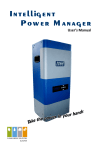
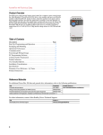
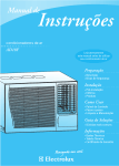
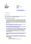
PowerFlex 70 Adjustable Frequency AC Drive
Additional Resources
These documents contain additional information concerning related products from Rockwell Automation.
Resource
Description
PowerFlex 70 Adjustable Frequency AC Drive User Manual, publication 20A-UM001
Provides the basic information needed to start up and troubleshoot the PowerFlex®
70 Adjustable Frequency AC Drive.
PowerFlex 70 and 700 Reference Manual - Volume 1, publication PFLEX-RM001
Provides detailed information for specifications and dimensions, operation, and
dynamic brake selection for the drive.
PowerFlex 70 Adjustable Frequency AC Drive Installation Instructions, publication 20A-IN009
Provides the five basic steps needed to install and perform a basic startup of the
PowerFlex 70 drive.
Wiring and Grounding Guidelines for Pulse Width Modulated (PWM) AC Drives,
publication DRIVES-IN001
Provides the basic information needed to properly wire and ground Pulse Width
Modulated (PWM) AC drives.
Industry Installation Guidelines for Pulse Width Modulated (PWM) AC Drives,
publication DRIVES-AT003
Provides basic information for enclosure systems and environmental/location
considerations (to help protect against environmental contaminants), and power and
grounding considerations needed to properly install AC drives.
Safety Guidelines for the Application, Installation and Maintenance of Solid State Control,
publication SGI-1.1
Provides general guidelines for the application, installation, and maintenance of
solid-state control.
Preventive Maintenance of Industrial Control and Drive System Equipment,
publication DRIVES-TD001
Provides a guide to performing preventive maintenance.
Guarding Against Electrostatic Damage, publication 8000-4.5.2
Provides practices for guarding against Electrostatic damage (ESD)
Industrial Automation Wiring and Grounding Guidelines, publication 1770-4.1
Provides general guidelines for installing a Rockwell Automation industrial system.
Product Certifications website, http://www.ab.com
Provides declarations of conformity, certificates, and other certification details.
You can view or download publications at http://www.rockwellautomation.com/literature/. To order paper copies of
technical documentation, contact your local Allen-Bradley distributor or Rockwell Automation sales representative.
Product Overview
PowerFlex 70 drives are designed to worldwide standards providing out-of-thebox performance around the globe. Available ratings include these options:
• 0.5…25 Hp output at 240V AC input
• 0.5…50 Hp output at 480V AC input
• 0.5…50 Hp output at 600V AC input
The PowerFlex 70 drive can be used with a full featured LCD human interface
module (HIM) that provides multilingual text for startup, metering,
programming, and troubleshooting.
The PowerFlex 70 can be programmed for either volts per hertz, sensorless
vector, or vector control with FORCE™ Technology to cover a wide range of
applications from fans to extruders.
Optional internal communication modules provide fast and efficient control and/or data exchange with host controllers
over popular interfaces. These interfaces include: DeviceNet, EtherNet, ControlNet, remote I/O, serial communications,
and other open control and communication networks. Computer tools such as DriveExplorer™ and DriveTools™ SP assist
with programming, monitoring, and troubleshooting the PowerFlex 70.
2
Rockwell Automation Publication 20A-TD001J-EN-P - July 2014
PowerFlex 70 Adjustable Frequency AC Drive
Catalog Number Explanation
Position Number
1-3
4
5-7
8
9
10
11
20A
B
2P2
a
b
c
14
A
3
A
d
e
f
15
Y
Y
N
N
C
0
g
h
i
j
k
l
a
c3
c5
ND Rating
ND Rating
Type
20A
PowerFlex 70
400V, 50 Hz Input
Code
Amps
kW (Hp)
1P3
1.3
0.37 (0.5)
2P1
2.1
3P5
16
600V, 60 Hz Input
Frame
Code
Amps
kW (Hp)
A
0P9
0.9
0.37 (0.5)
0.75 (1.0)
A
1P7
1.7
0.75 (1.0)
A
3.5
1.5 (2.0)
A
2P7
2.7
1.5 (2.0)
A
5P0
5.0
2.2 (3.0)
B
3P9
3.9
2.2 (3.0)
B
8P7
8.7
4.0 (5.0)
B
6P1
6.1
4.0 (5.0)
B
011
11.5
5.5 (7.5)
C
9P0
9.0
5.5 (7.5)
C
015
15.4
7.5 (10)
C
011
11
7.5 (10)
C
022
22
11 (15)
D
017
17
11 (15)
D
030
30
15 (20)
D
022
22
15 (20)
D
037
37
18.5 (25)
D
027
27
18.5 (25)
D
043
43
22 (30)
D
032
32
22 (30)
D
ND Rating
060
60
30 (40)
E
041
41
30 (40)
E
208V, 60 Hz Input
072
72
37 (50)
E
052
52
37 (50)
E
b
Voltage Rating
Voltage
Ph.
B
240V AC
3
C
400V AC
3
D
480V AC
3
E
13
Drive
Code
Code
12
600V AC
3
c1
Code
Amps
kW (Hp)
Frame
2P2
2.5
0.37 (0.5)
A
4P2
4.8
0.75 (1.0)
A
6P8
7.8
1.5 (2.0)
B
9P6
11
2.2 (3.0)
B
015
17.5
4.0 (5.0)
C
022
25.3
5.5 (7.5)
D
028
32.2
7.5 (10)
D
042
43
11 (15)
D
054
62.1
15 (20)
E
070
78.2
18.5 (25)
E
c2
A
CE certification testing has not been
performed on 600V class drives.
c4
ND Rating
d
480V, 60 Hz Input
Code
Amps
kW (Hp)
1P1
1.1
0.37 (0.5)
Enclosure
Frame
A
2P1
2.1
0.75 (1.0)
A
3P4
3.4
1.5 (2.0)
A
5P0
5.0
2.2 (3.0)
B
8P0
8.0
3.7 (5.0)
B
011
11
5.5 (7.5)
C
014
14
7.5 (10)
C
11 (15)
D
D
022
22
ND Rating
027
27
15 (20)
240V, 60 Hz Input
034
34
18.5 (25)
D
040
40
22 (30)
D
Frame
Frame
Code
Amps
kW (Hp)
2P2
2.2
0.37 (0.5)
A
052
52
30 (40)
E
4P2
4.2
0.75 (1.0)
A
065
65
37 (50)
E
6P8
6.8
1.5 (2.0)
B
9P6
9.6
2.2 (3.0)
B
015
15.3
4.0 (5.0)
C
022
22
5.5 (7.5)
D
028
28
7.5 (10)
D
042
42
11 (15)
D
054
54
15 (20)
E
070
70
18.5 (25)
E
Code
Enclosure
A
Panel Mount - IP 20, NEMA/UL
Type 1
C
Wall/Machine Mount = IP66,
NEMA/UL Type 4X/12 for
indoor use only
F
Flange Mount - Front Chassis =
IP 20, NEMA/UL Type 1; Rear
Heatsink = IP66, NEMA/UL
Type 4X/12 for indoor/outdoor
use
G
Wall/Machine Mount - IP54,
NEMA/UL Type 12
Only available on Frame E.
e
HIM
Code
Interface Module
0
Blank Cover
3
Full Numeric LCD
5
Prog. Only LCD
Only available with NEMA 4X, option C.
See Catalog Number Explanation (continued) on page 6 for more drive options.
Rockwell Automation Publication 20A-TD001J-EN-P - July 2014
5
PowerFlex 70 Adjustable Frequency AC Drive
Catalog Number Explanation (continued)
Position Number
1-3
4
5-7
8
9
10
11
12
13
14
15
16
20A
B
2P2
A
3
A
Y
Y
N
N
C
0
a
b
c
d
e
f
g
h
i
j
k
l
f
i
k
Documentation
Emission Class
Control & I/O
Code
Type
A
Manual
N
No Manual
g
Code
Rating
Code
Control
Safe-Off
A
Filtered
A & B Frames (Optional)
C, D, & E Frames (Standard)
N
Standard
N/A
C
Enhanced
No
G
Enhanced
Yes
N
Not Filtered
A & B Frames (Optional)
C, D, & E Frames
Brake IGBT
Code
w/Brake IGBT
Y
Yes
600V Frames A through D available only
without filter (Cat. Code N). 600V Frame E
available only with filter (Cat. Code A).
No longer available for sale.
Not available as factory installed option for
600V ratings.
l
Increases size to Frame B.
h
Feedback
j
Internal Brake Resistor
6
Code
w/Resistor
Y
Yes
Code
Network Type
N
No
C
ControlNet (Coax)
Comm Slot
D
DeviceNet
E
N
EtherNet/IP
None
Rockwell Automation Publication 20A-TD001J-EN-P - July 2014
Code
Feedback
0
No Feedback - Enhanced
Control
1
5V/12V Encoder w/Enhanced
Control
PowerFlex 70 Adjustable Frequency AC Drive
Approximate Dimensions and Weights
This section provides the approximate dimensions for the drives.
Figure 1 - Frames A…E
IP20/66 (NEMA / UL Type 1/4X/12)
A
D
Flange Mount
C
A
C
E
B
B
F
D
E
Table 14 - Frame Dimensions, mm (in.)
Frame Size Dimension
A
B
C
IP20, NEMA / UL Type 1
A
122.4 (4.82) 225.7 (8.89) 179.8 (7.08)
B
171.7 (6.76) 234.6 (9.24) 179.8 (7.08)
C
185.0 (7.28) 300.0 (11.81) 179.8 (7.08)
D
219.9 (8.66) 350.0 (13.78) 179.8 (7.08)
E
280.3 (11.04) 555.8 (21.88) 207.1 (8.15)
IP66, NEMA / UL Type 4X/12
B
171.7 (6.76) 239.8 (9.44) 203.3 (8.00)
D
219.9 (8.66) 350.0 (13.78) 210.7 (8.29)
E
280.3 (11.04) 555.8 (21.88) 219.8 (8.65)
Flange Mount
A
156.0 (6.14) 225.8 (8.89) 178.6 (7.03)
B
205.2 (8.08) 234.6 (9.24) 178.6 (7.03)
C
219.0 (8.62) 300.0 (11.81) 178.6 (7.03)
D
248.4 (9.78) 350.0 (13.78) 178.6 (7.03)
E
280.3 (11.04) 555.8 (21.88) 207.1 (8.15)
D
E
F
Weight (1)
kg (lb)
94.2 (3.71)
122.7 (4.83)
137.6 (5.42)
169.0 (6.65)
200.0 (7.87)
211.6 (8.33)
220.2 (8.67)
285.6 (11.25)
335.6 (13.21)
491.0 (19.33)
5.8 (0.23)
5.8 (0.23)
5.8 (0.23)
5.8 (0.23)
6.9 (0.27)
2.71 (6.0)
3.60 (7.9)
6.89 (15.2)
9.25 (20.4)
18.60 (41.0)
122.7 (4.83) 220.2 (8.67) 5.8 (0.23)
169.0 (6.65) 335.6 (13.21) 5.8 (0.23)
200.0 (7.87) 491.0 (19.33) 6.9 (0.27)
3.61 (8.0)
9.13 (20.1)
18.60 (41.0)
123.0 (4.84)
123.0 (4.84)
123.0 (4.84)
123.0 (4.84)
117.2 (4.61)
2.71 (6.0)
3.60 (7.9)
6.89 (15.2)
9.25 (20.4)
18.60 (41.0)
55.6 (2.19)
55.6 (2.19)
55.6 (2.19)
55.6 (2.19)
89.9 (3.54)
–
–
–
–
–
(1) Weights include HIM and standard I/O.
Rockwell Automation Publication 20A-TD001J-EN-P - July 2014
29
PowerFlex 70 Adjustable Frequency AC Drive
Table 18 - Specifications
Category
Protection
Environment
Specification
Drive
AC input overvoltage trip
AC input undervoltage trip
Bus overvoltage trip
Bus undervoltage output shutoff
Bus undervoltage fault level
Nominal bus voltage
All Drives
Heat sink thermistor
Drive overcurrent trip
Software current limit
Hardware current limit
Instantaneous current limit
Line transients
Control logic noise immunity
Power ride-thru
Logic control ride-thru
Ground fault trip
Short circuit trip
Altitude
Maximum surrounding air temperature
without derating
IP20, NEMA / UL Type 1
flange mount
IP66, NEMA / UL Type 4X/12 (indoor)
Cooling fan operation
Frames A and C
Frames B, D, and E
Storage temperature (all const.)
Atmosphere
200…
208V
247V AC
120V AC
405V DC
153V DC
160V DC
281V DC
240V
380/400
480V
600V
285V AC
138V AC
405V DC
153V DC
160V DC
324V DC
475V AC
233V AC
810VDC
305V DC
300VDC
540VDC
570V AC
280V AC
810V DC
437V DC
300V DC
648V DC
690V AC
345V AC
1013V DC
437V DC
375V DC
810V DC
690V
Monitored by microprocessor overtemp trip
20…160% of rated current
200% of rated current (typical)
220…300% of rated current (dependent on drive rating)
Up to 6000 volts peak per IEEE C62.41-1991
Showering arc transients up to 1500V peak
15 milliseconds at full load
0.5 seconds minimum, 2 seconds typical
Phase-to-ground on drive output
Phase-to-phase on drive output
1000 m (3300 ft) max without derating
0…50 °C (32…122 °F)
0…50 °C (32…122 °F)
0…40 °C (32…104 °F)
Relative humidity
Shock
Vibration
Surrounding environment
Pollution degree:
Pollution degree 1 and 2
Pollution degree 3 and 4
See Table 19 on page 37 for descriptions
of pollution degree rating.
Fan operates when power is applied.
Fan operates when power is applied and in Run condition.
–40…70 °C (–40…158 °F)
Important: Drive must not be installed in an area where the ambient
atmosphere contains volatile or corrosive gas, vapors, or dust. If the drive is
not going to be installed for a period of time, store the drive where it is not
exposed to a corrosive atmosphere.
5…95% non-condensing
15 g peak for 11 ms duration (±1.0 ms)
0.152 mm (0.006 in.) displacement, 1 g peak
All enclosures are acceptable for pollution degree 1 and 2.
An enclosure that meets or exceeds IP54, NEMA / UL Type 12, is required for
pollution degree 3 and 4.
Table 19 - Pollution Degree Ratings According to EN 61800-5-1
Pollution
Degree
1
2
3
4
Description
No pollution or only dry non-conductive pollution occurs. The pollution has no influence.
Normally only non-conductive pollution occurs. Occasionally a temporary conductivity, caused by condensation, is expected
when the drive is out of operation.
Conductive pollution or dry non-conductive pollution occurs, that becomes conductive due to condensation, and is expected.
The pollution generates persistent conductivity caused, for example, by conductive dust, rain, or snow.
Rockwell Automation Publication 20A-TD001J-EN-P - July 2014
37