1
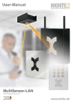
Syncro
Multi-loop
Analogue Addressable
Fire Control Panel
User Manual
Issue 06 Aug 2007
Product Manuals/Man-1057 Syncro User
Index
Section
Page
1. Introduction ...................................................................................................... 2
2. Safety............................................................................................................... 3
3. Panel Controls ................................................................................................... 3
3.1 Access Level 1 ........................................................................................ 3
3.2 Access Level 2 ........................................................................................ 4
4. Panel Operation................................................................................................. 5
4.1 Fire Event ............................................................................................... 5
4.2 Fault Event ............................................................................................. 5
4.3 Pre-alarm event...................................................................................... 5
4.4 Evacuate event ....................................................................................... 5
4.5 Alert event ............................................................................................. 6
5. Access 2 Menu .................................................................................................. 6
5.1 Disablements.......................................................................................... 6
5.2 View Devices .......................................................................................... 7
5.3 Test Zones ............................................................................................. 7
5.4 Set System Time .................................................................................... 8
5.5 Contamination Status ............................................................................. 8
5.6 Access Level 3 ........................................................................................ 8
6. Panel printer – replacing printer paper................................................................. 8
7. Routine Maintenance.......................................................................................... 8
1. Introduction
The Syncro is an analogue addressable fire detection and alarm control panel approved and certified by
BSI to meet the requirements of EN54-2: 1997.
It is capable of covering a maximum of 96 zones (500 zones on a network) with 2 or 4 detection loops and
126 devices per loop for Apollo protocol and 127 devices per loop for Hochiki protocol.
Syncro also supports loop-powered sounders & beacons.
Any number of devices can be allocated to any zone ensuring that any system configuration can be easily
accommodated.
Each detection device is allocated a message of up to 40 characters (including spaces) to assist in the
location of the devices.
The Syncro control panel offers an extensive list of features and options for the control and monitoring of
plant, equipment and sounders.
The range of compatible devices includes optical and ionisation smoke sensors, heat sensors, multisensors, switch monitors and relay or bell controllers. Interfaces to conventional detection systems can
also be catered for using zone-monitoring devices.
Product Manuals/Man-1057 Syncro User
Page 2 of 8
2. Safety
Suppliers of articles for use at work are required under section 6 of the Health and Safety at Work act
1974 to ensure as reasonably as is practical that the article will be safe and without risk to health when
properly used.
An article is not regarded as properly used if it is used ‘without regard to any relevant information or
advice’ relating to its use made available by the supplier.
This product should be installed, commissioned and maintained by trained service personnel in accordance
with the following:
(i)
IEE regulations for electrical equipment in buildings
(ii)
Codes of practice
(iii)
Statutory requirements
(iv)
Any instructions specifically advised by the manufacturer
According to the provisions of the Act you are therefore requested to take such steps as are necessary to
ensure that you make any appropriate information about this product available to anyone concerned with
its use.
This equipment is designed to be operated from 230V 50Hz mains supplies and is of class 1 construction.
As such it must be connected to a protective earthing conductor in the fixed wiring of the installation and
a readily accessible double pole disconnect device shall be incorporated in the fixed wiring.
Failure to ensure that all conductive accessible parts of this equipment are adequately bonded to the
protective earth will render the equipment unsafe.
3. Panel Controls
3.1 Access Level 1
The front panel contains controls for
operating the panel.
Lamp Test
Press this button to illuminate all front
panel indicators and validate correct
operation.
Silence Buzzer
This button will switch the internal
buzzer from continuous to intermittent,
and will illuminate the Buzzer Silenced
panel indicator. No other sounder
outputs will be affected by this button
operation.
More Fires
This button is used to view suppressed
fire events. In the case of multiple fire
activations, or when fire activation
information has been temporarily
suppressed for menu navigation, the
fire events can be quickly restored and
viewed by pressing this button.
Fig 1 – Syncro Front Panel
More Events
This button is used to view all other suppressed events. In the case of multiple panel events or when any
event information has been temporarily suppressed for menu navigation, this button is used to display the
view events list.
Product Manuals/Man-1057 Syncro User
Page 3 of 8
Menu Navigation (up / down / left / right / enter / exit)
These are used to enter the password for access level 2 and are also used to navigate the Access 2
Facilities Menu.
Help (?)
This button offers additional information relating to the current status of the control panel. e.g. if the
panel is in an alarm or fault condition then advice on the recommended action will be displayed or if a
menu function is being accessed then help relating to that function will be displayed.
3.2 Access Level 2
Access level 2 can be reached by pressing any of the menu navigation buttons. This will then request the
user to enter the correct Access level 2 password (a 4 digit number) followed by the Enter button.
The factory default password for Access level 2 is 2222.
The Access level 2 password can be changed at commissioning to meet customer’s requirements. Enter
the Access level 2 password in the space below for future reference.
Access level 2 will be required by the end user to acknowledge alarms and reset the system.
Any persons responsible for the fire alarm system should be aware of the access level 2 password to
enable the panel controls.
Without this password it will not be possible to acknowledge alarms or reset the system so it is most
important that the responsible person knows the password.
ACCESS 2 PASSWORD
………………………….
Silence Alarm / Acknowledge
This button is normally used to mute any fire warning sounders fitted to the Syncro panel. These sounders
are installed throughout the protected premises and are used to evacuate the premises.
In some cases, the fire warning sounders may be delayed; to allow a search time before building
evacuation commences. In this case, the “Delay Active” panel indicator will be illuminated. If the
Acknowledge Alarm button is pressed during the Delay Active period, the sounders may either be
permanently muted or the delay may be extended to the second stage delay time. This will depend upon
the panel configuration and cannot be amended by the end user.
If there is a second fire activation during an Active Delay, then all delays are cancelled and outputs will
operate in accordance with the building fire strategy.
Re-sound Alarm
If any fire warning sounders have been muted using the Acknowledge Alarm button, then pressing the Resound Alarm will re-energise all muted sounders.
Reset
This button is used to reset any activation that is defined as a latching input type. These will include fire
and pre-alarm events. In general, fault events are non-latching and cannot be cleared by operation of the
Reset button. These events will clear when the fault input is cleared.
Function 1 & 2
These two buttons are software programmable inputs that may be used to perform customer-defined
actions. The default operation of these buttons is to perform no action (transparent input).
The operation of these buttons should be entered in the box below;
Function 1 button
……………………………………………………
……………………………………………………
Function 2 button
……………………………………………………
……………………………………………………
Product Manuals/Man-1057 Syncro User
Page 4 of 8
4. Panel Operation
4.1 Fire Event
In the event of a fire, the twin red FIRE lamps and the appropriate Fire Zone indicator will flash (if fitted).
Details of the fire activation (address and location text) will be given in the LCD Status display.
The fire warning sounders will sound throughout the building and the panel fire contact, alarm contact and
fire routing outputs will be energised.
The panel buzzer will be pulsing, but can be silenced by pressing the Silence Buzzer button.
To silence the fire warning sounders, press any of the menu navigation buttons and enter the Access 2
password (given in section 3.2) then press the Enter button.
The panel controls will now be enabled and will remain enabled for about 1 minute after the last key has
been pressed.
Pressing the Silence Alarm / Acknowledge button will now silence the sounders. The sounders can be
started again if required by pressing the Re-Sound Alarm button
The system can be reset by pressing the Reset button.
If there are more than two fire events on the system then these may be viewed in the text display by
pressing the More Fires button.
4.2 Fault Event
If there is a fault on the system, the yellow General Fault indicator will be flashing and there may be
other fault LED indications which identify the nature of the fault.
The Fault Contact and Monitored Aux. O/P will be energised and the panel buzzer will be sounding
continuously.
Details of the fault will be described in the text display.
The panel buzzer can be silenced at any time by pressing the Silence Buzzer button.
If there are more than two fault events on the system then these may be viewed in the text display by
pressing the More Events button.
4.3 Pre-alarm event
Sensors or inputs can generate a pre-alarm. A pre-alarm is used to warn of a slow change in the analogue
level from detection devices, typically due to a smouldering fire. When a pre-alarm is generated, the
control panel will illuminate the pre-alarm LED and will sound the internal buzzer continuously. The
address and location of the source of the pre-alarm will be indicated in the LCD status display.
The source of the pre-alarm input should be investigated.
The panel buzzer can be silenced at any time by pressing the Silence Buzzer button.
If there are more than two fault events on the system then these may be viewed in the text display by
pressing the More Events button.
4.4 Evacuate event
An input on the system can be configured to create an Evacuate event. Operation of an evacuation input
will cause the twin red FIRE lamps to illuminate and all sounder devices to be operated continuously
The panel buzzer will sound continuously and the source of the evacuation event will be shown in the LCD
status display.
The panel buzzer can be silenced at any time by pressing the Silence Buzzer button.
To silence the fire warning sounders, press any of the menu navigation buttons and enter the Access 2
password (given in section 3.2) then press the Enter button.
The panel controls will now be enabled and will remain enabled for about 1 minute after the last key has
been pressed.
Pressing the Acknowledge Alarm button will now silence the sounders
If the source of the event is a latching input, then pressing the Reset button will reset the system.
Product Manuals/Man-1057 Syncro User
Page 5 of 8
4.5 Alert event
An input on the system can be configured to create an Alert event. Operation of an Alert input will cause
all sounder devices to be pulsed on a 1 second cycle.
The panel buzzer will sound continuously and the source of the alert event will be shown in the LCD status
display.
The panel buzzer can be silenced at any time by pressing the Silence Buzzer button.
To silence the fire warning sounders, press any of the menu navigation buttons and enter the Access 2
password (given in section 3.2) then press the Enter button.
The panel controls will now be enabled and will remain enabled for about 1 minute after the last key has
been pressed.
Pressing the Acknowledge Alarm button will now silence the sounders
If the source of the event is a latching input, then pressing the Reset button will reset the system.
5. Access 2 Menu
There are a number of menu options available at access level 2. To view this menu, press the Right (2)
pointing arrow key and enter the Access 2 password (given in section 3.2) then press the Enter button.
The panel controls will now be enabled and will remain enabled for about 1 minute after the last key has
been pressed.
When in Access 2, press any of the four navigation buttons to view the Access 2 menu.
To navigate the menu, use the Up (1) and Down (3) buttons to move the cursor to the required menu
option. Use the Right (2) button to select the highlighted menu option. Use the Left (4) button to exit
back to the main menu. Use the Enter button to input the required information and the Exit button to
cancel any data selection. Pressing the Help (?) button will display the help screen appropriate to the
current menu selection.
ACCESS LEVEL 2
Disablements
View devices
Test Zones
Set system time
Contamination Status
Access level 3
Main menu items available at access levels 2:
5.1 Disablements
Any disablements made using this menu will remain active until the disablement is cleared by manual
intervention at the panel.
Disable Immediate Output Response
If any outputs are configured to be delayed (an Access Level 3 configuration operation), then EN54
requires that these outputs are not delayed, unless set to do so at Access Level 2. This menu option allows
delays to outputs to be activated, by disabling the immediate response facility.
Disable Zones
All detection devices, including manual call points, are disabled in the selected zone.
NOTE: When a device is disabled, the Syncro panel ignores the analogue value reported by the device. All
other faults for the device (missing device, double address, internal fault, type changed, bad data etc.) are
still reported by the Syncro panel.
Disable Addresses
Any loop device can be disabled using this menu option. In devices with more than one input or output,
then each sub-address may be individually disabled.
Product Manuals/Man-1057 Syncro User
Page 6 of 8
NOTE: When a device is disabled, the Syncro panel ignores the analogue value reported by the device. All
other faults for the device (missing device, double address, internal fault, type changed, bad data etc.) are
still reported by the Syncro panel.
Disable Sounders
This menu option is used to disable all sounder outputs fitted to the control panel. A sounder output is
defined as any output that has been set to respond to the Silence and Evacuate panel commands.
Sounder outputs may be directly wired to the control panel (Sounder circuit 1 to 4) or loop driven devices.
The Sounder Fault / Disabled LED indicator will be illuminated, as well as the General Disablement
Indicator.
Disable Panel Outputs
This menu option allows the following panel outputs to be independently disabled;
•
Fire Contact
•
Alarm Contact
•
Fire Routing Output
•
Extinguishant Output
•
Fault Contact
•
Monitored Aux. O/P
When the Fire Routing output is disabled, the front panel Fire Routing Fault / Disabled indicator and
General Disablement indicator will be permanently illuminated.
View / Restore Disablements
To cancel any disablements, there are two options. The first is to scroll through each individual menu
option, then toggle any disablements to the normal condition. The second, preferred option, is to use the
View / Restore Disablements option. This menu option will allow the user to scroll through all active
disablements and individually enable each disablement by pressing the Enter button.
5.2 View Devices
This menu option permits the user to view all addresses connected to each detection circuit. For each
address & sub-address, the LCD status display will give the device type, zone and location text. In
addition, analogue devices will give an indication of the analogue value of the current device.
For digital input devices (Manual call points, switch monitor units etc) the input state is given, either as
Normal or Activated. For output devices, the output state will be shown as either Normal, Intermittent of
Continuous.
This menu is used by experienced personnel to investigate the current status of the system and may help
in fault finding techniques.
5.3 Test Zones
Test Zones
Each zone may be individually put in to a Test Mode condition. When test mode is selected, the devices in
the zone may be tested and the Syncro panel will automatically reset after 3 seconds. This is used for one
man testing of the fire system.
When a zone is put in to test mode, the user is prompted to select the sounder response behaviour for the
selected zone. When set to the ON position, all sounder outputs will sound for the duration of the fire
event. The sounders will be muted when the panel automatically resets.
NOTE: On systems with a high number of Loop powered sounders fitted, all sounders may not be able to
activate within the 3 second fire period and therefore loop sounder confirmation may be intermittent.
View & Restore Zones in Test
To cancel any zones in test, there are two options. The first is to scroll through each zone in the Test Zone
menu, then toggle any active zones to the normal condition. The second is to use the View / Restore
Zones in Test option. This menu option will allow the user to scroll through all active zones in test and
individually enable each disablement by pressing the Enter button.
Product Manuals/Man-1057 Syncro User
Page 7 of 8
5.4 Set System Time
This menu option is used to set the panel date and time. This is necessary so that any events are
accurately logged in the event log and on the panel printer (if fitted). The panel does not automatically
compensate for daylight saving time.
5.5 Contamination Status
Any detection devices that exceed 85% of the limit for the manufacturers working range during the daily
calibration sequence are added to a contaminated device menu. At this stage, the panel will not notify the
user of a fault for the contaminated devices.
This menu option allows the user to see any devices approaching their maintenance fault limits and to
prevent unnecessary faults being reported from dirty detection devices.
This menu is typically used as a preventative maintenance feature.
5.6 Access Level 3
This menu option is used to enter the access 3 password for the engineering function menu.
Details of the options available at Access level 3 can be found in the Syncro Product manual.
6. Panel printer – replacing printer paper
The Syncro panel is available with or without an internal printer.
The printer is of the thermal type and requires heat sensitive paper rolls. When the paper rolls are nearly
finished, a red line will be seen on one (or both) sides of the printer paper. As soon as this red line is
visible, the fire system service company should be informed and a trained service engineer should replace
the printer paper.
To gain access to the panel printer, it is necessary to open the Syncro door and expose the internal
components of the control panel, including the mains supply terminations. This makes it unsuitable for the
end user to change the printer paper on this product.
7. Routine Maintenance
Syncro control panels do not require any specific maintenance but should the control panel become dirty it
can be wiped over with a barely damp cloth. Detergents or solvents should not be used to clean the panel
and care must be taken that water does not enter the enclosure.
The control panel contains sealed lead acid batteries to provide standby power in the event of mains
failure.
These batteries have a life expectancy of around 4 years. It is recommended that these batteries be
annually tested in accordance with the battery manufacturer’s recommendations to determine their
suitability for continued standby applications.
Routine testing of the fire alarm system in accordance with BS5839: Part 1: 2002 will identify any
malfunction of the control panel and any malfunction should be reported to the fire alarm maintenance
company immediately.
Detection devices are automatically calibrated on a daily basis and any devices that fail the detector
manufacturer requirements will be notified as a maintenance fault. The contamination status menu is also
useful in determining detection devices that are approaching their working range limits (see 5.5 above).
Product Manuals/Man-1057 Syncro User
Page 8 of 8