1
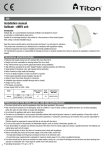
Triton Systems Anti-Condensation Products Data Pack Triton Contact Details: Triton Systems Ltd. Units 3 – 5 Crayford Commercial Centre, Greyhound Way, Crayford, Kent DA1 4HF Tel: 01322 318 830 Fax: 01322 524 017 Email:[email protected] www.tritonsystems.co.uk 0923 02/15 CONTENTS: 1. Introduction and general information 2. Triton Surface Cleanser Data Sheet 3. Triton Anti-Mould Emulsion Data Sheet 4. Triton Home Dry Vent Air Brick Data Sheet 5. Triton Home Dry Vent Core Drill Data Sheet 6. Triton Heatrec 1003 Heat Recovery Unit Data Sheet 7. Triton Elix Extractor Fan Data Sheet 8. Triton Elix Running Cost Calculations 9. Triton Elegance Extractor Fan Data Sheet 10. Triton Elegance Running Cost Calculations 11. Triton Loft Positive Pressure Unit Data Sheet 12. Triton Loft Positive Pressure Unit Installation Instructions 13. Triton Flat Positive Pressure Unit Data Sheet 14. Triton Flat Positive Pressure Unit Installations Instructions 0923 02/15 Introduction and General Information Background and preventative measures Condensation is the most common cause of dampness in buildings and affects properties of all types and ages. In particular it is directly associated with black mould growth. Triton offers a comprehensive range of products to control condensation including passive air vents, extractor fans, heat recovery ventilators and positive pressure units. Effects of condensation Black Mould growth is often the first visible sign of condensation, usually present on decorative surfaces such as wallpaper. The mould and its spores also cause a musty odour and often give rise to respiratory health problems. When condensation occurs in roof spaces or sub floor areas, timbers in those areas can become damp and susceptible to dry or wet rot. Condensation is more common in the colder months when water vapour levels are higher. It should also be noted that sometimes the problem can occur away from the site of water vapour production. For example water vapour produced in a bathroom or kitchen may diffuse through the house and condense on the walls of a cold bedroom. It should be noted that Black Mould can only flourish on the pure water associated with condensation – therefore it is not an indication of rising damp. Primary Measures 1. Improve Ventilation Ventilation can be achieved by a variety of measures including simply opening the windows, however the most effective method to control local condensation problems is the installation of a powered extractor fan. However, where the condensation is a widespread problem, a more successful approach would be the installation of a positive pressure system. This will draw air in to the roof space, gently push it down in to the property, and cause moisture laden air to be continually pushed out. 2. Apply Heat A constant low level background heat will gradually warm wall surfaces and reduce the risk of condensation. Secondary Measures The following supporting measures may be required in severe cases of condensation: remove excess water sources such as bottled gas heaters; insulate cold surfaces; insulate solid walls and floors; prevent water penetration which may be the cause of cool walls. Other Useful Measures 1. Dehumidifiers A strategically placed dehumidifier, to lower the water content of the air, can be very effective. 2. Surface cleansers and anti-mould paints Surface cleansers or anti-mould washes are an effective short term measure to remove Black Mould from walls and other surfaces. Anti-mould paints are particularly useful in kitchens and bathrooms or other areas where condensation is often difficult to control and where there is a high risk of mould growth. They must not be decorated over and will remain effective for many years. 3. General advice When cooking, washing, bathing or drying clothes, keep the door closed and the window open. This will prevent warm, moist air moving to colder areas of the building. Triton SURFACE CLEANSER Description To prepare and cleanse surfaces before the use of antimould and condensation control products or any other paints. Packaging Supplied as a concentrate for dilution with water (1 part concentrate to 19 parts water by volume. Pack size 250ml Properties Concentrate contains <10% w/w Quaternary Ammonium Halide dissolved in water. Preparation Prepare the surfaces by removing non-washable and loose material, e.g. flaking paint, grease, dirt, mould or wallpaper. SURFACE CLEANSER can be used to “wet in” wallpaper before removal. Make good any surface defects and rub down to a smooth finish. Wash down with SURFACE CLEANSER using a sponge, scrubbing brush or cloth. Allow to dry thoroughly. Apply second wash in badly soiled areas and allow to dry. Prime any bare areas of plaster and woodwork with ANTIMOULD EMULSION, thinned up to 10% with water if necessary. Apply appropriate ANTIMOULD OR ANTICONDENSATION COATING. Product Information Drying Time: Practical Coverage: 1-4 hours normally. 6-8m²/litre when diluted depending on the porosity and roughness of the surface. Application: By sponge, cloth or brush. General There are basic measures to assist in the control of condensation and the black mould. The Antimould and condensation control products complement these basic controls and will prevent these problems occurring for many years. These methods are particularly helpful in the domestic environment but can be applied equally to most commercial premises. It is always important to reduce the risk of condensation by observing the following simple recommendations: Ensure rooms are always warm and property ventilated, maintaining some low heating throughout the day if possible. When cooking, washing, bathing or drying clothes, keep the door closed and the window open – this prevents warm moist air moving to colder areas of the building. In cold weather keep some heating on all the time. If a paraffin or flueless gas heater is used ensure a window is open a little (every litre of paraffin produces about 1 litre of water). Improve internal/external wall insulation. Use ventilation systems where appropriate. Health And Safety Refer to Material Safety Data Sheet for each product. For further information please contact: Triton Chemical Manufacturing Co Ltd T/a Triton Systems Units 3 – 5 Crayford Commercial Centre, Greyhound Way, Crayford, Kent DA1 4HF Tel: 01322 318830 Fax: 01322 524017 Email: [email protected] www.tritonsystems.co.uk Ref: Triton Surface Cleanser 08/11 1 Triton ANTIMOULD EMULSION AQUEOUS EMULSION FUNGICIDAL COATING (MOULDING INHIBITING) Description An excellent, premium quality low odour antimould coating guaranteed to protect against unsightly and unhygienic black mould even when there is persistent condensation. The antimould biocide is combined throughout the paint film, which is formulated to impart toughness, elasticity, water resistance and durability to the finish. Preparation 1. Remove any loose material such as old paint, grease, dirt, mould or defective wallpaper. Triton SURFACE CLEANSER can be used for wetting in purposes when removing wallpaper. 2. Make good any defects in the surface and rub down to a smooth finish. 3. Wash and clean all surfaces (walls, ceilings, window frames and joinery) using Triton SURFACE CLEANSER. If necessary clean badly affected areas a second time. 4. Allow to dry thoroughly. 5. If necessary, apply an appropriate primer or sealer to new, unprimed or porous plaster and wooden surfaces or bare metal. 6. For new or porous surfaces use Triton ANTIMOULD EMULSION thinned up to 10% with clean tap water. Allow to dry thoroughly. After priming, metal surfaces should be painted with two coats Acrylic Gloss. Application 1. 2. 3. 4. 5. Apply Triton ANTIMOULD EMULSION using a brush or roller. STIR THOROUGHLY BEFORE USE. Apply two coats of Triton ANTIMOULD EMULSION allowing sufficient drying time between coats. Clean equipment with clean tap water before the paint dries. N.B. If an unfinished, textured wallpaper (blown vinyl, woodchip) or similar is to be used then it should be hung after the Triton SURFACE CLEANSER has fully dried. The wallpaper should be coated with Triton ANTIMOULD EMULSION as above. Technical Specification Coverage: Drying Time: Thinning: Uses: Colours: Packaging: Storage: Shelf Life: 10-12m² per litre but an extra allowance should be made for rough or porous surfaces. Touch dry 1 hour and recoatable after 2-4 hours dependent on conditions. Use clean tap water but do not exceed 10% by volume. Can be used as a primer and undercoat for Acrylic Eggshell or Acrylic Gloss. Brilliant White, Magnolia and selected pastel colours. Specific colours may be supplied depending upon requirements. 2.5 and 5.0 litres in HPDE containers. Store above 5°C in dry conditions. Keep the container tightly sealed and away from children. Correctly stored, the unopened product has a shelf life of 12 months. Health and Safety See separate Health & Safety sheet. For further information please contact: Triton Chemical Manufacturing Co Ltd T/a Triton Systems Units 3 – 5 Crayford Commercial Centre, Greyhound Way, Crayford, Kent DA1 4HF Tel: 01322 318830 Fax: 01322 524017 Email: [email protected] www.tritonsystems.co.uk Ref: Triton Antimould Emulsion 07/11 1 TRITON HOME VENT- TECHNICAL DATA SHEET Triton Home Dry Vent offer a range of passive ventilation units designed to allow water vapour to escape from a building in a controlled way. The patent pending triple action filter promotes the escape of damp air with minimal heat loss. Cold draughts are restricted by a specially designed thermal core within the filter. The Triton Home Dry Vent cavity liner is constructed from High Impact Polystyrene (HIP) to reduce cold bridging and provide increased strength and resistance to distortion. Triton Home Dry Vent extension kits are available to suit all wall thicknesses. Condensation affects a large number of older properties due to the increase in water production brought about by modern lifestyles. At the same time, doors and windows are draught proofed and chimney flues sealed. The result can be unhealthy mould growth on cold surfaces and in poorly ventilated areas. Triton Home Dry Vent is designed to ventilate bedrooms and living rooms where the constant background ventilation it provides allows water vapour to escape. One air brick ventilator is usually sufficient for a singe room of up to 20m² floor area, alternatively two core drill ventilators can be installed. Each unit is supplied with positioning and installation instructions. For kitchens and bathrooms where water production is likely to be more spontaneous, mechanical ventilation should be used. At a typical inside temperature of 20° and relative humidity of 70% 1m³ of air contains 0.0125kg of water, creating a vapour pressure of 1.4 kPa above, which there is an increased risk of mould growth. At an air velocity of 0.09m/s Triton Home Dry Vent diffuses up to 0.12kg of water per hour or 2.8 litres of water over a 24 hour period powered only by the vapour pressure differential that exists between inside a property and the external environment. Model Air brick ventilator Core drill ventilator High rise ventilator Velocity Air diffusion / hour Water diffusion / hour 0.09m/s 0.09m/s 0.09m/s 9.34m³ 3.98m³ 3.98m³ 0.12kg 0.05kg 0.05kg Water dissipated over 24 hours 2.8 litres 1.2 litres 1.2 litres Water vapour diffusion through the range of Triton Ultrovent ventilators at an air velocity of 0.09 m/s, 70% relative humidity and a temperature of 20°C. Air brick ventilator Core drill ventilator High rise ventilator 0.08m/s 2.5 litres 1 litre 1 litre 0.09m/s 2.8 litres 1.2 litres 1.2 litres 0.1m/s 3.1 litres 1.3 litres 1.3 litres 0.11m/s 3.4 litres 1.4 litres 1.3 litres The effect of changes in air velocity on water vapour diffusion through the range of Triton Home Dry Vent ventilators at 70% relative humidity and a temperature of 20°C Triton Contact Details: Triton Chemical Manufacturing Co Ltd T/a Triton Systems Units 3-5 Greyhound Commercial Centre, Greyhound Way, Crayford, Kent DA1 4HF Tel: 01322 318830 Fax: 01322 524017 Email: [email protected] www.tritonsystems.co.uk Triton Home Vent Core Drill Ventilator Triton Home Dry Vent offer a range of passive ventilation units designed to allow water vapour to escape from a building in a controlled way. The patent pending triple action filter promotes the escape of damp air with minimal heat loss. Cold draughts are restricted by a specially designed thermal core within the filter. Condensation affects a large number of older properties due to the increase in water production brought about by modern lifestyles. At the same time, doors and windows are draught proofed and chimney flues sealed. The result can be unhealthy mould growth on cold surfaces and in poorly ventilated areas. Triton Home Dry Vent is designed to ventilate bedrooms and living rooms where the constant background ventilation it provides allows water vapour to escape. For kitchens and bathrooms where water production is likely to be more spontaneous, mechanical ventilation should be used. At a typical inside temperature of 20°C and relative humidity of 70% 1m³ of air contains 0.0125kg of water, creating a vapour pressure of 1.7 kPa above, which there is an increased risk of mould growth. At an air velocity of 0.09 m/s Triton Ultrovent diffuses up to 0.12kg of water per hour or 2.8 litres of water over a 24 hour period powered only by the vapour pressure differential that exists between inside a property and the external environment. Installation of the Triton Ultrovent Core Drill Ventilator requires a 132mm core drill. MODEL VELOCITY Core drill ventilator 0.09m/s AIR DIFFUSION / HOUR 3.98m³ WATER DIFFUSION/ HOUR 0.05kg WATER DISSIPATED OVER 24 HOURS 1.2 litres Water vapour diffusion through the range of Triton Home Dry Vent Ventilators at an air velocity of 0.09 m/s, 70% relative humidity and a temperature of 20°C. 0.08m/s 0.09m/s 0.1m/s 0.11m/s Core drill ventilator 1 litres 1.2 litres 1.3 litres 1.4 litres The effect of changes in air velocity on water vapour diffusion through the range of Triton Home Dry Vent Ventilators at 70% relative humidity and a temperature of 20°C. Cavity liner size Aperture size Length Extension Core drill ventilator 125mm dia 127mm dia 300mm 440mm each For further information please contact: Triton Chemical Manufacturing Co Ltd T/a Triton Systems Units 3 – 5 Crayford Commercial Centre, Greyhound Way, Crayford, Kent DA1 4HF Tel: 01322 318830 Fax: 01322 524017 Email: [email protected] www.tritonsystems.co.uk Ref: Triton Home Dry Vent Core Drill V entilator 04/2012 TRITON HEATREC 1003 SINGLE ROOM HEAT R E C O V E R Y Triton Heatrec 1003 • Single room, heat recovery unit • Provides low level continuous ventilation to control condensation • 3 speed axial fan • Choice of 2 low speeds at installation • For any domestic wet room • Standard, timer and humidistat models • Available in SELV (12v) version • Low noise levels and running costs • Compliant with Building Regulations Parts L1 2010 and F2010 GENERAL FEATURES • • • • • • • • • • • • • • • Exhausts directly to the outside through a wall Up to 70% of heat recovered Complete with 100mm dia ducting and terminal kit (ducting available in different lengths) Continuous air movement ensures that any condensation quickly evaporates Can be installed completely from the inside – ideal for high rise buildings Can be fitted at any angle For new build or to replace existing 100mm or 150mm unit Runs continuously at pre-‐selected choice of two speeds (fixed at installation) Speed 1 operates at 9 l/s (factory set) Speed 2 operates at 14 l/s Anti-‐vibration gasket Speed can be boosted to maximum (29 l/s) using various switches Energy saving ventilation Extremely low running costs Low carbon footprint TECHNICAL FEATURES OTHER MODELS AVAILABLE Shockproof, high quality • TRITON Heatrec 1003DT – 3 speed, technopolymer casing continuous running with timer (timer does not activate unless fan has been • Energy efficient tube heat exchanger running for 2 minutes to avoid • Designed using latest wind tunnel unnecessary night-‐time operation), technology and CFD simulations overrun timer and pull-‐cord. • 43,000 hour life motors with • TRITON Heatrec 1003HDT – with maintenance free and long life ball comfort timer, humidistat and pull-‐cord bearings. • Operates in ambient temperatures up • TRITON Heatrec 1003LV – 3 speed, continuous running with pull-‐cord – to 40°C LOW VOLT (SELV) • Double insulated – no earth required • TRITON Heatrec 1003DTLV – 3 speed, • Summer mode – to prevent continuous running, with comfort overheating in summer and aid in timer, over run time and pull-‐cord LOW summer cooling VOLT (SELV) • Integral frost-‐stat – proportionately • TRITON Heatrec 1003HDTLV – 3 speed, reduces intake motor speed as continuous running, with comfort temperature falls timer, humidistat and pull-‐cord LOW • IPX4 – Splashproof rated – can safely VOLT (SELV) be installed in Zones l and ll. Models with 150 dia duct and higher COMPLIES WITH performance will shortly be available • Part L1 2010 of Building Regulations for enhanced energy saving capability • Part F 2010 of Building Regulations for reliable, efficient ventilation • IEC 60335-‐2-‐80, BT 2006/95/CE and EMC 2004/108/CE European Directive against radio interference and electro-‐ magnetic compatibility • CE marked • including ErP Directive 2015 ompliant Triton Systems can supply all accessories for use with these units, fire dampers, air vCalves, ducting, outside grilles and wall cowls. Additionally, Triton Systems offers a • design service to ensure that the unit installed is the best possible to provide efficient, effective, low energy and low running cost ventilation. Triton Systems can also organise installation, commissioning and maintenance of these products. For further information please contact: Triton Systems Ltd Units 3 – 5 Crayford Commercial Centre, Greyhound Way, Crayford, Kent DA1 4HF Tel: 01322 318830 Fax: 01322 524017 Email: [email protected] www.tritonsystems.co.uk Ref: Triton Heatrec 1003 – 10/14 TRITON ELIX Decentralised mechanical extract ventilation – dMEV TRITON dMEV – Elix – ELX1003 • • • • • • • • Energy efficient EC motor Provides low level continuous ventilation to control condensation 3 speed centrifugal fan Choice of 2 low speeds at installation For wall or ceiling For any domestic wet room Low noise levels and running costs Compliant with Building Regulations Parts L1 2010 and F2010 GENERAL FEATURES • Exhausts directly to the outside or through long lengths of ducting (up to 15m) • Runs continuously at preselected choice of two speeds (fixed at installation) • Speed 1 operates at 8 l/s (factory set) • Speed 2 operates at 14 l/s • Anti-vibration gasket • Easily removable, washable polypropylene filter • Speed boosted to maximum (28 l/s) using integral pull cord or by: - Remote switch / light switch - PIR Sensor - DRH240 (dynamic remote humidistat) • Energy saving ventilation • Extremely low running costs • Low carbon footprint • 5 year warranty TECHNICAL FEATURES OTHER MODELS AVAILABLE: • Shockproof, high quality technopolymer casing • Designed using latest wind tunnel techniology and CFD simulations • Profile increases the fluid dynamics • EC Induction motor with thermal protection • 43,000 hour life motors with maintenance free and long life ball bearings • Operates in ambient temperatures up to 40°C • Double insulated – no earth required • IPX4 – Splashproof rated – can safely be installed in Zones I and II COMPLIES WITH • Part L1 2010 of Building Regulations for enhanced energy saving capability • Part F 2010 of Building Regulations for reliable, efficient ventilation • IEC 60335-2-80, BT 2006/ 95/CE and EMC 2004 / 108 / CE European Directive against radio interference and electro-magnetic compatibility • CE marked • SAP Q eligible • Energy Saving Trust best Practice Compliant • ELX1003DT – 3 speed, continuous running with comfort timer (timer does not activate unless fan has been running for 2 minutes to avoid unnecessary night-time operation) and pull-cord • ELX1003HDT – with comfort timer, humidistat and pull-cord • ELX1003LV – 3 speed, continuous running with pullcord – LOW VOLT (SELV) • ELX1003DTLV – 3 speed, continous running, with comfort timer, overrun timer and pullcord LOW VOLT (SELV) • ELX1003HDTLV – 3 speed, continous running, with comfort timer, humidistat and pull-cord – LOW VOLT (SELV) TECHNICAL CHARACTERISTICS Airflow 1/sec Model ELX1003 Power – Watts Speed 1 Speed 2 Max Speed 1 Speed 2 Max 8 14 28 2 3.2 16 All Results with Rigid Duct RESULTS for SAP CALCULATIONS BST Best Practice Specific Fan Unit Configuration Performance Power (W/I/s) Compliant In room – kitchen 0.22 Yes In room – wetroom 0.16 Yes Through wall – kitchen 0.17 Yes Through wall – wetroom 0.14 Yes Figures from BRE test results at minimum flow rate conditions RESULTS for Approved Document F Flow Rate (I/sec) 13.0 8.0 13.0 8.3 Flow Rate – Wind condition (l/sec) 12.9 7.8 12.9 8.1 % reduction Of Total Flow Rate 1 3 1 2 TYPICAL SPECIFICATION Supply and install a TRITON ELX1003 high performance, energy efficient centrifugal fan which has been tested and is SAP Q Eligible and suitable for ALL domestic wet rooms as supplied by Triton Systems Ltd, Units 3-‐5 Crayford Commercial Centre, Greyhound Way, Crayford, Kent DA1 4HF. The fan is to be suitable for installation either into a wall or ceiling (with the appropriate accessories) and to have an air intake around the whole perimeter and have a footprint of no more than 180mm square. The fan is to be continuous running at its low speed (with a choice of two lower speeds) and be capable of being boosted to maximum speed by means of an integral pull cord or (with the cord removed) a remote switch, PIR sensor or humidistat. The fan should have a specific fan power (as tested to BRE) of no higher than 0.22w/l/s in a kitchen and 0.16w/l/s in a bathroom. The fan must not exceed 2.0w power consumption on the lowest speed. The fan casing should be made of shock-‐proof, high quality technopolymer, and should have an EC induction motor with maintenance-‐free, long life ball bearings, and up to a 43,000 hour life. It should be protected with a thermal cut-‐out. The fan should be double insulated and be IPX4 splash-‐proof protected suitable for installation into Zones I and ll. The fan is to comply with IEC60335-‐2-‐80, lvd2006/95/CE and EMC2004/108/CE European Directive against radio interference and electro-‐ magnetic compatibility, and be CE marked. The fan should be 5 year manufacturer’s warranty and be supplied with a user guide as required. Only approved accessories should be used: Wall Plates – as required Wall terminations – all wall terminations must use the approved wall cowl or high rise kit. Triton Systems can supply all accessories for use with these units, including fire dampers, air valves, ducting, outside grilles and wall cowls. Additionally, Triton Systems offers a design service to ensure that the unit installed is the best possible to provide efficient, effective, low energy and low running cost ventilation. Triton Systems can also organise installation, commissioning and maintenance of these products. PERFORMANCE (curves are for guidance only) Speed 180 Speed 1 160 140 120 100 Speed 2 Maximum 80 60 40 20 0 0 0 5 10 15 20 25 30 10 20 30 Airflow litres/second 40 50 Airflow m³/hr 60 70 80 90 100 110 DIMENSIONS -‐ mm For further information please contact: Triton Systems Ltd Units 3 – 5 Crayford Commercial Centre, Greyhound Way, Crayford, Kent DA1 4HF Tel: 01322 318830 Fax: 01322 524017 Email: [email protected] www.tritonsystems.co.uk Ref: Triton ELIX – 10/14 RUNNING COST CALCULATIONS FOR TRITON ELIX EXTRACT FAN All the fan powers used are based on the BRE SAP Appendix Q test results as this is the only truly independent uniform test available. The BRE test is conducted at boost speeds of 8 l/s for bathrooms and 13 l/s for kitchens. This is fine for comparison purposes but does not provide a true representative for calculating actual running costs. In a typical scenario the fan will only be on boost for an hour or two at most each day and not for twenty four hours. Therefore we take the efficiency figure, known as Specific Fan Power (SFP), from BRE which is shown in W/l/s. This is used to calculate how many watts the fan will actually use on trickle speed, which is considerably lower than when on boost. Below is a typical example. KITCHEN The Triton Elix has a BRE test result of 0.17 W/l/s at 13 l/s – kitchen boost; so the total amount of watts used by a Triton Elix would be: Time per day (hrs) SFP (W/l/s) Extract Rate (l/s) Total Watts BOOST 2hrs 0.17 W/l/s 13l/s 4.42W TRICKLE 22hrs 0.17 W/l/s 9l/s (approx. 33.06W trickle rate) Kitchen TOTAL 24hrs 38.08W per day BATHROOM In the bathroom the BRE test result of 0.17 W/l/s at 8 l/s – bathroom boost; so the total amount of watts used by a Triton Elix would be: Time per day (hrs) SFP (W/l/s) Extract Rate (l/s) Total Watts BOOST 2hrs 0.14 W/l/s 8l/s 2.24W TRICKLE 22hrs 0.14 W/l/s 5l/s (approx. 15.40W trickle rate) Bathroom TOTAL 24hrs 17.64 per day So to ventilate a typical dwelling to current system 3 building regulation requirements: uses 49.28 watts per day (29.12w + 20.16w) Kitchen Bathroom Daily Total Yearly Total Electricity Annual W W W kW Costs Running Cost 38.08W 17.64W 55.72W 20.34kW 14.5p/kW/hr £2.95/year (approx. £1.30 per fan) For further information please contact: Triton Systems Ltd Units 3 – 5 Crayford Commercial Centre, Greyhound Way, Crayford, Kent DA1 4HF Tel: 01322 318830 Fax: 01322 524017 Email: [email protected] www.tritonsystems.co.uk TRITON ELEGANCE – EL1003 Decentralised mechanical extract ventilation – dMEV TRITON dMEV – Elegance– EL1003 • • • • • • • • Energy efficient EC motor – lowest energy consumption in the UK Provides low level continuous ventilation to control condensation 3 Speed axial fan Choice of 2 low speeds at installation Wall, ceiling or window (with additional window kit) For any domestic wet room Low noise levels and running costs Compliant with Building Regulations Parts L1 2010 and F 2010 GENERAL FEATURES • • • • • • • • • • Exhausts directly to the outside (through wall, or window installation with additional window kit, or with medium length ducting – up to 6m) Runs continuously at preselected choice of two speeds (fixed at installation) Speed 1 operates at 9.5 l/s (factory set) Speed 2 operates at 13.8 l/s anti-vibration gasket Speed boosted to maximum (28.5l/s) using integral pull cord or by: -‐ Remote switch/light switch -‐ PIR Sensor -‐ DRH240 (Dynamic remote humidistat Patented anti-turbulence deflectors ensure very low noise levels and optimum performance Energy saving ventilation Extremely low running costs Low carbon footprint 5 year warranty TECHNICAL FEATURES OTHER MODELS AVAILABLE: • Shockproof, high quality • EL1003DT – 3 speed, continuous technopolymer casing running with comfort timer (timer does not activate unless fan has • Designed using latest wind tunnel been running for 2 minutes to avoid technology and CFD simulations unnecessary night-time operation) • EC induction motor with thermal and pull-cord protection • EL1003HDT – with comfort timer, • 43,000 hour life motors with humidistat and pull-cord maintenance free and long life ball • EL1003LV – 3 speed, continuous bearings operates in ambient running with pull-cord – LOW VOLT temperatures up to 40°C (SELV) • Double insulated – no earth required • EL1003DTLV – 3 speed, • IPX4 - Splashproof rated – can continuous running, with comfort safely be installed in Zones l and ll timer, overrun timer and pull-cord LOW VOLT (SELV) COMPLIES WITH • Part L1 2010 of Building Regulations • EL1003HDTLV – 3 speed, continuous running, with comfort for enhanced energy saving timer, humidistat and pull-cord – capability LOW VOLT (SELV) • Part F2010 of Building Regulations for reliable, efficient ventilation • IEC 60335-2-80, BT 2006/95/CE and EMC 2004/108/CE European Directive against radio interference and electro-magnetic compatibility • CE Marked • SAP Q eligible • Energy Saving Trust Best Practice Compliant TECHNICAL CHARACTERISTICS Airflow 1/sec Model Power – Watts dBA (@3m in free field) Speed 1 Speed 2 Max Speed 1 Speed 2 Max Speed 1 Speed 2 max 9.5 13.8 28.5 1.5 3 4.6 15.1 17.3 31.4 EL1003 All Results with Rigid Duct Unit Configuration RESULTS for SAP CALCULATIONS Specific Fan Power (W/I/s) In room – kitchen 0.13 In room – wetroom 0.16 Through wall – kitchen 0.15 Through wall – wetroom 0.16 Figures from BRE test results at minimum flow rate conditions BST Best Practice Performance Compliant Yes Yes Yes Yes RESULTS for Approved Document F Flow Rate (I/sec) 13.0 8.4 13.0 8.2 Flow Rate – Wind condition (l/sec) 12.7 8.0 12.7 7.8 % reduction Of Total Flow Rate 2 5 2 5 TYPICAL SPECIFICATION Supply and install a TRITON EL1003 high performance, energy efficient axial fan which has been tested and is SAP Q Eligible and suitable for ALL domestic wet rooms as supplied by Triton Systems Ltd, Units 3-‐5 Crayford Commercial Centre, Greyhound Way, Crayford, Kent DA1 4HF. The fan is to be suitable for installation either into a wall or ceiling (with the appropriate accessories) and to have an air intake around the whole perimeter and have a footprint of no more than 160mm square. The fan is to be continuous running at its low speed (with a choice of two lower speeds) and be capable of being boosted to maximum speed by means of an integral pull cord or (with the cord removed) a remote switch, PIR sensor or humidistat. The fan should have a specific fan power (as tested to BRE) of no higher than 0.13w/l/s in a kitchen and 0.16w/l/s in a bathroom. The fan must not exceed 15.1 dB(A) noise level and 1.5w power consumption on the lowest speed. The fan casing should be made of shock-‐proof, high quality technopolymer, and should have an EC induction motor with maintenance-‐free, long life ball bearings, and up to a 43,000 hour life. It should be protected with a thermal cut-‐out. The fan should be double insulated and be IPX4 splash-‐proof protected suitable for installation into Zones I and ll. The fan is to comply with IEC60335-‐2-‐80, LVD2006/95/CE and EMC2004/108/CE European Directive against radio interference and electro-‐ magnetic compatibility, and be CE marked. The fan should have a 5 year manufacturer’s warranty and be supplied with a user guide as required. Only approved accessories should be used: Wall Plates – as required Window kits – as Wall terminations – all wall terminations must use the approved wall cowl or high rise kit. Triton Systems can supply all accessories for use with these units, including fire dampers, air valves, ducting, outside grilles and wall cowls. Additionally, Triton Systems offers a design service to ensure that the unit installed is the best possible to provide efficient, effective, low energy and low running cost ventilation. Triton Systems can also organise installation, commissioning and maintenance of these products. PERFORMANCE (curves are for guidance only) 40 Speed Speed 1 35 30 25 20 Speed 2 Maximum 15 10 5 0 0 0 5 10 15 20 25 30 10 20 30 Airflow litres/second 40 50 Airflow m³/hr 60 70 80 90 100 110 DIMENSIONS -‐ mm For further information please contact: Triton Systems Ltd Units 3 – 5 Crayford Commercial Centre, Greyhound Way, Crayford, Kent DA1 4HF Tel: 01322 318830 Fax: 01322 524017 Email: [email protected] www.tritonsystems.co.uk Ref: Triton Elegance – EL1003 – 10/14 RUNNING COST CALCULATIONS FOR TRITON ELEGANCE EXTRACT FAN All the fan powers used are based on the BRE SAP Appendix Q test results as this is the only truly independent uniform test available. The BRE test is conducted at boost speeds of 8 l/s for bathrooms and 13 l/s for kitchens. This is fine for comparison purposes but does not provide a true representative for calculating actual running costs. In a typical scenario the fan will only be on boost for an hour or two at most each day and not for twenty four hours. Therefore we take the efficiency figure, known as Specific Fan Power (SFP), from BRE which is shown in W/l/s. This is used to calculate how many watts the fan will actually use on trickle speed, which is considerably lower than when on boost. Below is a typical example. KITCHEN The Triton Elegance has a BRE test result of 0.13 W/l/s at 13 l/s – kitchen boost; so the total amount of watts used by a Triton Elegance would be: Time per day (hrs) SFP (W/l/s) Extract Rate (l/s) Total Watts BOOST 2hrs 0.13 W/l/s 13l/s 3.38W TRICKLE 22hrs 0.13 W/l/s 9l/s (approx. 25.74W trickle rate) Kitchen TOTAL 24hrs 29.12W per day BATHROOM In the bathroom the BRE test result of 0.16 W/l/s at 8 l/s – bathroom boost; so the total amount of watts used by a Triton Elegance would be: Time per day (hrs) SFP (W/l/s) Extract Rate (l/s) Total Watts BOOST 2hrs 0.16 W/l/s 8l/s 2.56W TRICKLE 22hrs 0.16 W/l/s 5l/s (approx. 17.60W trickle rate) Bathroom TOTAL 24hrs 20.16W per day So to ventilate a typical dwelling to current system 3 building regulation requirements: uses 49.28 watts per day (29.12w + 20.16w) Kitchen Bathroom Daily Total Yearly Total Electricity Annual W W W kW Costs Running Cost 29.12W 20.16W 49.28W 17.99kW 14.5p/kW/hr £2.61/year (approx. £1.30 per fan) For further information please contact: Triton Systems Ltd Units 3 – 5 Crayford Commercial Centre, Greyhound Way, Crayford, Kent DA1 4HF Tel: 01322 318830 Fax: 01322 524017 Email: [email protected] www.tritonsystems.co.uk TRITON LOFT PPU POSITIVE INPUT VENTILATION For small/medium/large domestic properties • Whole House Ventilation System • Low Noise Levels • Extremely Low Running Costs • Quick Fit Installation • Available with Heater • Standard Five Year Guarantee GENERAL FEATURES • Positive pressure ventilation provides effective, draught free ventilation and prevents condensation forming • Easy to install – the TRITON Loft PPU can be used both in the refurbishment of older properties where condensation is a particular problem as well as in new build. • The TRITON Loft PPU introduces tempered air, drawn in through the loft, to create positive pressure in the building. • Tempered, filtered, fresh air enters the living areas from the fan, via a short length of flexible ducting, through a discreet ceiling mounted diffuser. • The fresh air circulates throughout the building give draught-‐free ventilation eventually dissipating through openings around the property • Runs continuously to provide a constant background air change and maintain a healthy and comfortable environment. the moisture content of the air outside is normally lower than that in doors, the level of humidity it reduced, helping to • Since eliminate the damaging effects of condensation. • A TRITON LOFT PPU provides extra security – there is no need to open windows. noise levels are extremely low •• The The system is very economical and can cost less than £5 per year to run • The TRITON LOFT PPU is guaranteed for 5 years TECHNICAL FEATURES • For small, medium or large domestic properties • Easy loft installation • Choice 3 speed levels (set at installation) • Robust construction – fan casing is an integral, one piece unit with a filter box attached. • Air inlet is provided on all sides of the unit • Incorporates a specially developed fan / motor assembly. Motor mounted on sealed self-‐lubricating bearings protected with thermal cut out • Double insulated • Maximum ambient temperature 40 °C • Complete with ceiling diffuser, flexible duct, work drive clips, plasterboard fixings and screws and attenuation mounts. • Easy to maintain – motor and fan blades should be checked after every six months of service. Filters can be cleaned but should be replaced every two years. MODEL Supply Weight Extract Capacity COMPLIES WITH • Part L1 2010 of Building Regulations for enhanced energy saving capability • Part F 2010 of Building Regulations for reliable, efficient ventilation • EU RoHS Directive Compliant • Conforms to requirements of EC Council directives relating to Electromagnetic Compatibility and Electrical Safety: 2006/95/CE (LVD), 2004/108/CE (EMC), EN60335-‐2-‐80 • CE marked Power Sound Level Low Medium High Low Medium High Low Medium High TRITON LOFT PPU 230v, 50Hz 7 kg 155m³ / hr, 43 l/s 235m³ / hr, 65 l/s 303m³ hr, 84 l/s 6 watts 12 watts 18 watts 20 dBA 25 dBA 30 dBA Typical Specification Supply and install a TRITON LOFT PPU positive pressure fan supplied by TRITON SYSTEMS LTD, Units 3-‐5 Crayford Commercial Centre, Greyhound Way, Crayford, Kent DA1 4HF This should be designed for easy loft installation and be able to provide effective, draught free ventilation by introducing tempered air drawn in though the loft and creating a positive pressure in the building. The indrawn air is then dissipated through openings around the property, thus providing a constant, background air change. The fan should have a choice of three lower speeds on installation and run automatically at that level (chosen according to the size of the building). The fan should be supplied with a ceiling diffuser, flexible ducting, worm drive clops and attenuation mounts. The fan should comply with all current IEE, EC and Building Regulations requirements and also be BRE Digest 398 compliant. Triton Systems offers a design service to ensure that the unit installed is the best possible to provide efficient, effective, low energy and low running cost ventilation. Triton Systems can also organise installation, commissioning and maintenance of these products. For further information please contact: Triton Systems Ltd Units 3 – 5 Crayford Commercial Centre, Greyhound Way, Crayford, Kent DA1 4HF Tel: 01322 318830 Fax: 01322 524017 Email: [email protected] www.tritonsystems.co.uk Ref: TRITON LOFT PPU – 10/14 "Triton Loft" Positive Input Whole House Ventilation Unit for Small, Medium or Large Domestic Properties Installation, Operating and Maintenance Instructions Page 2 "TrITOn LOfT" POSITIVE InPUT WHOLE HOUSE VEnTILATIOn UnIT InSTALLATIOn, OPErATIng & MAInTEnAnCE InSTrUCTIOnS Safety notice It is important to read this Instruction Manual carefully before installing or using the product. following these instructions will ensure that your ventilation system is installed, commissioned and used properly and continues to operate effectively. Triton Systems will not be held responsible and will not accept liability for any damage caused to persons or property through failure to follow the guidance provided in this manual. It should always be available with the product for easy reference. general Information The Triton Loft positive input fan works on the principle of introducing tempered air drawn in through the loft, creating a positive pressure in the building, which then dissipates through openings around the property to provide a constant background air change. As the moisture content of the air outside is normally lower than that indoors, the level of humidity is reduced, helping to eliminate the damaging effects of condensation. The tempered, filtered fresh air is introduced via a short length of flexible ducting attached to a ceiling-mounted inlet valve. Supplied as standard, this valve diffuses the air horizontally along the ceiling, providing effective, draught-free ventilation. The system automatically provides a fresh, tempered airflow into the home with minimal power consumption. The system is designed to run continuously and should nOT be switched off except for maintenance or filter replacement. It is important to follow the advice in this user manual and correctly install and maintain the system to ensure a healthy and comfortable indoor environment. Installation IT IS IMPOrTAnT THESE InSTrUCTIOnS ArE rEAD fULLY BEfOrE InSTALLATIOn • • • • • • • • • • • This product should not be used for any purpose other than that for which it was designed and as shown in this leaflet All packaging should be removed and the unit checked for damage in transit. If there is any damage, please contact your supplier Packing material should not be left within the reach of children or unskilled people and any hazardous parts must be disposed of responsibly (polystyrene, plastic, polypropylene, etc.). In order to comply with Construction (Design & Management) regulations, sufficient access for safe maintenance (recommended on an annual basis), or removal following installation, MUST be provided for this product. fire Safety regulations and current Building regulations. In order to comply with these, it may be necessary to fit fire dampers or other similar devices. flue gases from fuel-burning equipment must not be drawn into a living area. If any room from which air is extracted contains a fuel burning appliance, such as a central heating boiler, then its flue must be of the sealed or balanced flue type, or allowance must be made for an adequate supply of air into the room for the fan and the fuel-burning appliance. The unit must nOT be installed: - where there is excessive oil or grease - where there are hazardous gases, liquids or vapours that are flammable or corrosive - in ambient temperatures above 40ºC - where it could be exposed to outside elements - rain, sun, snow etc Where possible the unit should nOT be installed directly above a bedroom or living room. Care should be taken to ensure that ducting is free from blockages The product must be connected to the electricity supply by means of a double-pole switch with a minimum contact opening distance greater than 3 mm. The product should only be connected to the mains electricity supply or electrical outlet if: - your electrical voltage and frequency correspond to those shown on the rating label. - the capacity of your electricity supply is sufficiently powerful to operate the product at its maximum power. Page 3 Installation of the appliance MUST be carried out by a qualified and suitably competent person and should be carried out in clean, dry conditions where dust and humidity are at minimal levels. The unit is not suitable for installation to the exterior of the dwelling. Handling • • • Care should be taken when transporting the unit. Dropping or knocking will damage the inner workings of the unit. The unit should always be stored in a clean, dry environment. Remove all packaging before installation. Pre-inspection • • Inspect the unit and electrical supply cord for any damage (damage must be repaired by a suitably qualified and competent person). Check all parts are supplied as shown. Parts list 1 x Triton Loft fan unit 1 x Filter Box 1 x Ceiling Valve Flexible Duct and Worm Drive Clips Plaster Board Fixings and Screws Attenuation Mounts Installation, Operation & Maintenance Instructions Any parts shortages or faults must be reported to the supplier immediately. Installation - for loft mounting 1. To fix the filter box, firstly remove screw 'A' and open the box as shown. Attach the box to two wooden bat tens fixed between the trusses using the screws, washers and rubber mounts supplied. Close the box and secure with screw 'A'. 2. Attach the fan section to the filter box using the two screws and plastic washers located in the protruding tabs on the filter box. 3. Attach the ducting to the fan unit, using worm screw ties 4. Attach black reducer to ducting, using worm screw ties. 5. Create a hole for valve in ceiling (approx. 200mm) 6. Remove front plate from valve and fix back plate to ceiling. 7. Attach front plate to affixed valve backplate. 8. Attach ducting to valve via black reducer using the reducer and secure with the worm drive clips supplied. Use the minimum length of ducting necessary and cut off any excess. 9. Connect to power supply and adjust the fan speed setting to the desired level Page 4 Wiring Instructions Cleaning and Maintenance Before any maintenance or cleaning operation, disconnect the appliance from the main power supply. The motor and the fan blades should be periodically checked and cleaned as necessary, usually after every six months of continuous operation. Maintenance should only be carried out by properly qualified personnel. To clean the inside of the fan, use a soft brush taking care not to cause any damage to the electrical wiring. During the normal cleaning operations, check the integrity of all appliance parts. The filters can be cleaned using the soft brush attachment of a vacuum cleaner. note: the filters should be replaced every two years. Replacements are available upon request. Triton Systems 3-5 Crayford Commercial Centre Greyhound Way Crayford Kent DA1 4HF Triton Loft: Oct 2014 Tel: 01322 318830 Email: [email protected] www.tritonsystems.co.uk E & O.E Product Data Sheet Triton Flat PPU Slimline, whole house, mechanical extract ventilation ■■ ■■ ■■ ■■ ■■ ■■ ■■ ■■ ■■ ■■ ■■ ■■ Energy efficient EC motor Efficient, low energy solution to controlling condensation and pollution Provides low level continuous ventilation in a kitchen and up to 5 wet rooms Variable choice of low (trickle) and boost speed at installation Compact ultra-low profile unit For loft, void, false ceiling or cupboard Requires only one discharge grille Low noise levels and running costs Available with 204 x 60mm spigot Available with humidistat Compliant with building regulations Parts L1 2010 and F 2010 Manufactured in UK to ISO 9001 General Features ■■ Up to 97 litre/sec at 50Pa – max 100 litre/sec capacity ■■ Suitable for areas up to 270m² ■■ Easy and economical installation and maintenance ■■ Can be angled horizontally or vertically ■■ Variable low (trick) and boost options ■■ Boost speed triggered by a switched live connections from: • A light switch (if more than one light switch is used, each one must be a double pole switch) • DRH240 (dynamic remote humidistat) • PIRFF (Passive infra-red) • THM (Thermostat) • A remote switch/pull cord ■■ Low noise levels (below 20dB(A) ■■ Low running costs ■■ Extra security – no need to open windows ■■ 3 year warranty Technical Features ■■ Compact, ultra-low profile ■■ Casting from steel, lined with acoustic material ■■ Low energy EC external rotor motor with sealed life bearings ■■ Backward curved impellors dynamically balanced ■■ Thermal overload protection ■■ Service and maintenance panel easily accessible ■■ Pre-wired for easy electrical connection ■■ Complete with mounting bracket and anti-vibration plate ■■ Operates in temperature up to 60°C ■■ Manufactured in UK to ISO 9001 ■■ IPX4 rated Complies with ■■ Part L1 2010 of Building Regulations for enhanced energy saving capability ■■ Part F 2010 of Building Regulations for reliable, efficient ventilation ■■ EU RoHS Directive Compliant ■■ Conforms to requirements of EC Council directives relating to Electromagnetic Compatibility and Electrical Safety: 2006/95/CE (LVD), 2004/108/CE (EMC), EN60335-2-80 ■■ CE marked ■■ SAP Q eligible ■■ Energy Saving Trust Best Practice Compliant Control Features ■■ Variable Adjustment – trickle and boost speeds set at installation ■■ Boost Setting (via switched live) DUCT RUNS INSTALLATION EXAMPLE Triton Systems can supply all accessories for use with these units including air filter cassettes, silencers, fire dampers, air valves, ducting, outside grilles and wall cowls. Additionally, Triton Systems offers a design service to ensure that the unit installed is the best possible to provide efficient, effective, low energy and low running cost ventilation. Triton Systems can also organise installation, commissioning and maintenance of these products. Technical Characteristics Airflow l/sec Model Triton Flat PPU Power – Watts Max Boost Max trickle 80% 60% 40% Max Boost Max Trickle 80% 60% 40% 100 100 90 60 30 46 45 26 12 6 Results for SAP Calculations Energy Level Performance – using rigid ducting only Results for Approved Document F Specific Fan Power [W/I/s] EST Best Practice Performance Compliant Total Flow Rate [l/sec] Total Flow Rate [wind condition] [l/sec] % reduction of Total Flow Rate Kitchen + 1 additional wet room 0.20 Yes 21.0 19.3 8 Kitchen + 2 additional wet rooms 0.26 Yes 29.0 27.9 4 Exhaust Terminal Configuration Kitchen + 3 additional wet rooms 0.34 Yes 37.0 36.3 2 Kitchen + 4 additional wet rooms 0.44 Yes 45.0 44.2 2 Kitchen + 5 additional wet rooms 0.55 Yes 53.0 52.5 1 Figures from BRE test results at minimum flow rate conditions. Triton Flat PPU Curve Ref Characteristic in-Duct Sound Power Levels Mid Octave Frequency band 63 125 250 500 1k Case-radiated LpA[dB] @ 3m* 2k 4k 8k Max Boost Extract 85 83 79 68 67 60 52 45 Supply 83 85 76 73 67 64 57 49 Max Trickle Extract 85 83 79 68 61 60 52 45 Supply 83 85 76 73 67 64 57 49 Extract 82 80 75 68 57 56 47 39 Supply 80 83 73 69 63 60 52 44 Extract 70 72 62 57 45 42 32 25 Supply 69 74 59 57 50 45 36 27 Extract 48 50 42 34 31 28 21 16 Supply 47 51 40 39 34 30 24 17 80% 60% 40% 39 39 35 25 16 * Assumes spherical radiation under anechocic conditions Typical Specification Supply and install a Triton Flat PPU which gives low level, continuous ventilation to a kitchen and five other wet rooms. The unit should be for loft, void, false ceiling or cupboard installation and be no more than 184mm deep. The unit should incorporate a low energy EC external rotor motor with sealed for life bearings for low noise levels and low energy consumption with an SFP down to 0.20. It should have a variable choice of low (trickle) speed and boost options for optimum setting. The unit should be pre-wired for easy electrical connection. It should comply with all current IEE, EC and Building Regulations requirements, be SAP Q Eligible, be Energy Trust Best Practice Compliant and IPX4 rated and made in the UK by Triton Systems Ltd PERFORMANCE (curves are for guidance only) 400 Speed 40% 350 60% 80% 300 Max Trickle Available Pressure Pa Max Boost 250 200 150 100 50 0 0 0 10 20 50 30 100 40 150 50 60 200 70 250 80 300 90 100 350 110 400 Airflow m2/hr Triton Contact Details: Triton Systems Ltd. Units 3 – 5 Crayford Commercial Centre, Greyhound Way, Crayford, Kent DA1 4HF Tel: 01322 318 830 Fax: 01322 524 017 Email:[email protected] www.tritonsystems.co.uk 0916 01/15 "Triton Flat" Positive Input Whole House Ventilation Unit Wall Mounted Installation, Operating and Maintenance Instructions Page 2 "TrITOn FLAT" POSITIVE InPUT WHOLE HOUSE VEnTILATIOn UnIT InSTALLATIOn, OPErATIng & MAInTEnAnCE InSTrUCTIOnS FOr dOMESTIC PrOPErTIES TO 200M3 Safety notice It is important to read this Instruction Manual carefully before installing or using the product. Following these instructions will ensure that your ventilation system is installed, commissioned and used properly and continues to operate effectively. Triton Systems will not be held responsible and will not accept liability for any damage caused to persons or property through failure to follow the guidance provided in this manual. It should always be available with the product for easy reference. general Information The Triton Flatt positive input fan works on the principle of introducing tempered air and creating a positive pressure in the building, which then dissipates through openings around the property to provide a constant background air change. As the moisture content of the air outside is normally lower than that indoors, the level of humidity is reduced, helping to eliminate the damaging effects of condensation. The system automatically provides a fresh, tempered airflow into the home with minimal power consumption. The system is designed to run continuously and should nOT be switched off except for maintenance or filter replacement. It is important to follow the advice in this user manual and correctly install and maintain the system to ensure a healthy and comfortable indoor environment. Installation IT IS IMPOrTAnT THESE InSTrUCTIOnS ArE rEAd FULLY BEFOrE InSTALLATIOn • This product should not be used for any purpose other than that for which it was designed and as shown in this leaflet • All packaging should be removed and the unit checked for damage in transit. If there is any damage, please contact your supplier • Packing material should not be left within the reach of children or unskilled people and any hazardous parts must be disposed of responsibly (polystyrene, plastic, polypropylene, etc.). • In order to comply with Construction (design & Management) regulations, sufficient access for safe maintenance (recommended on an annual basis), or removal following installation, MUST be provided for this product. • Fire Safety regulations and current Building regulations. In order to comply with these, it may be necessary to fit fire dampers or other similar devices. • Flue gases from fuel-burning equipment must not be drawn into a living area. If any room from which air is extracted contains a fuel burning appliance, such as a central heating boiler, then its flue must be of the sealed or balanced flue type, or allowance must be made for an adequate supply of air into the room for the fan and the fuel-burning appliance. • The unit must nOT be installed: - where there is excessive oil or grease - where there are hazardous gases, liquids or vapours that are flammable or corrosive - in ambient temperatures above 40ºC - where it could be exposed to outside elements - rain, sun, snow etc • Where possible the unit should nOT be installed directly above a bedroom or living room. • Care should be taken to ensure that ducting iand entry and exits free from blockages • The product must be connected to the electricity supply by means of a double-pole switch with a minimum contact opening distance greater than 3 mm. • The product should only be connected to the mains electricity supply or electrical outlet if: - your electrical voltage and frequency correspond to those shown on the rating label. - the capacity of your electricity supply is sufficiently powerful to operate the product at its maximum power. This appliance is provided with thermal overload protection. If this is activated, the fan ust be disconnected from the mains electricity supply This will allow the overload device to re-set. After a brief period the fan can be restarted. Page 3 OPErATIOn 1. The Triton Flat is suitable for ceiling or wall installation (see below) 2. If one of the spigots is not connected to ducting a safety grille MUST be fitted to that spigot, so that it is impossible for any moving part to be touched. 3. These fans run continuously at a preset trickle speed. There is a choice of three trickle speeds, selectable during the installation. InSTALLATIOn 1. Remove the mounting bracket from the main cabinet by loosening the thumb screw on each side and slid ing the bracket sideways. (Do not remove the thumb screws completely). 2. Using the bracket as a template, mark the fixing holes on the mounting surface and drill and plug the holes. ( 4 x 6mm). Fix the bracket securely in place using four screws. 3. Mount the fan cabinet on to the bracket, taking note of the correct direction of airflow and slide sideways. (The air inlet into the cabinet is at the filter end). Tighten the fixing screws. 4. Connect the ducting to the spigots on the fan. note: During colder periods, there is a possibility of condensation forming on the surface of the ducting between the fan inlet and the outside wall. It is advised to keep the length of the inlet duct as short as possible. SPEEd SELECTIOn And ELECTrICAL COnnECTIOn note: Speed selection should be done before the unit is connected to the mains supply. 1. Remove the rectangular plastic cover on the front of the cabinet. Using the small jumper plug, select the speed required. (The normal factory setting is Speed 1). Replace the cover. 2. The unit is supplied with a 3-core cable. Connection should be made via a local means of isolation in compliance with current IEE Regulations. Important: This product must be earthed. 4Page 4 CLEAnIng And MAInTEnAnCE Before carrying out any maintenance or cleaning operations the mains electrical supply MUST be disconnected. The air filter must be cleaned every 6 – 12 months. To extract the filter from the cabinet, first remove the two screws from the filter slide plate. Pull out the filter and remove any dust/dirt using a vacuum cleaner. Refit the filter and screw in place. Should the filter be heavily contaminated, replacements can be obtained from your fan supplier. Triton Systems 3-5 Crayford Commercial Centre Greyhound Way Crayford Kent DA1 4HF Triton Flatt: Oct 2014 Tel: 01322 318830 Email: [email protected] www.tritonsystems.co.uk E & O.E