1
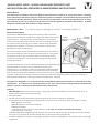
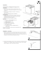
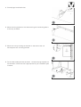
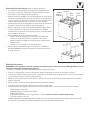
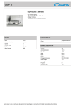
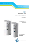
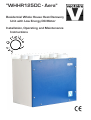
"WHHR125DC - Aera"
Residential Whole House Heat Recovery
Unit with Low Energy DC Motor
Installation, Operating and Maintenance
Instructions
"WHHR125DC- AERA" - WHOLE HOUSE HEAT RECOVERY UNIT
INSTALLATION AND OPERATING & MAINTENANCE INSTRUCTIONS
Safety Notice
It is important to read this Instruction Manual carefully before installing or using the product. Following
these instructions will ensure that your ventilation system is installed, commissioned and used properly and
continues to operate effectively. Vectaire will not be held responsible and will not accept liability for any damage caused to persons or property through failure to follow the guidance provided in this manual. It should
always be available with the product for easy reference.
WHHR125DC - Aera:
5"/125mm spigot, for dwellings up to 150m2, max capacity 280m3/hr
General Information
The Vectaire WHHR125DC- Aera heat recovery system provides
whole house mechanical ventilation to living areas, bedrooms, kitchen
and bathrooms. It extracts stale, contaminated air from kitchens,
utility rooms and bathrooms, and uses the heat recovered from this
air to warm fresh, incoming air to create a flow of fresh, filtered air
throughout the dwelling. The extract and intake air streams are
separated to avoid contamination.
Cooled
outgoing
stale air
Incoming
fresh air
The majority of the heat is reclaimed from extracted air and used, via
the heat exchange process, to warm incoming fresh air. The system
will operate continuously to create a stable, comfortable, healthy
environment avoiding the use of excessive energy and saving heat
already generated.
Outgoing stale air
The heat recovery unit must be installed vertically, and will generally be
sited in the loft of a house or the void above the ceiling in an
Warmed
fresh air
apartment, or in a cupboard. It will be connected by hidden ductwork
to vents sited in the ceilings of the rooms which are to be ventilated.
Each unit is commissioned individually so that the amount of air moved is tailored to suit the performance
required. There will be a facility to boost the extraction rate when desired (e.g when cooking or bathing, or
when pollutant levels rise). This may be done automatically or manually.
The system is designed to run continuously and should NOT be switched off except for maintenance or filter
replacement. It is important to follow the advice in this user manual and correctly install and maintain the
system to ensure a healthy and comfortable indoor environment.
Features
• SAP Q Eligible whole house heat recovery units giving continuous ventilation in the kitchen and up to six
additional wet rooms (using rigid ducting)
• low noise levels
• variable choice low (trickle) speed and boost options for optimum setting at installation
• boost speed can be triggered by a switched live connection from a variety of external devices including:
- PIRFF (passive infra red)*
- DRH240 (dynamic remote humidistat)*
- THM (thermostat)*
- a light switch (if more than one light switch is used, each one must be a double pole switch)
- a remote switch/pull cord
(*PIRFF, DRH240 and THM may have integral over-run timer which controls the length of time that the fan
will continue to operate at its boost speed after the boost has been switched off.)
• Installation MUST be carried out by suitably qualified personnel and MUST be in accordance with current IEE
regulations
Installation
IT IS IMPORTANT THESE INSTRUCTIONS ARE
READ FULLY BEFORE INSTALLATION
•
•
•
•
•
•
•
•
•
•
•
•
•
•
•
This product should not be used for any purpose other
than that for which it was designed and as shown
in this leaflet
All packaging should be removed and the unit checked
for damage in transit. If there is any damage, please
contact your supplier
The WHHR125DC- Aera will be installed vertically, and
generally be fitted into a cupboard, loft or ceiling void.
In order to comply with Construction (Design &
Management) Regulations, sufficient access for safe
maintenance (recommended on an annual basis), or
removal following installation, MUST be provided for
this product. See dimensions diagram.
Regulations and current Building Regulations. In order
to comply with these, it may be necessary to fit fire
dampers or other similar devices.
Flue gases from fuel-burning equipment must not
Incoming
be drawn into a living area. If any room from which
fresh air
Cooled
air is extracted contains a fuel burning appliance,
outgoing
Stale
Fresh
stale air
such as a central heating boiler, then its flue must
air in
air out
be of the sealed or balanced flue type, or allowance
must be made for an adequate supply of air into the
room.
The unit must NOT be installed:
- where there is excessive oil or grease
- where there are hazardous gasses, liquids or
vapours that are flammable or corrosive
- in ambient temperatures above 40ºC or lower than
0ºC
- in areas of excessive humidity or in a wet
environment
Where possible the unit should NOT be installed
directly above a bedroom or living room.
The condensation drain MUST be fitted
Care should be taken to ensure that ducting is free from blockages
External grilles should be located a minimum of 600mm from any flue outlet in accordance with all
Regulations
The unit must be connected to a 230v, 50Hz single phase electrical supply fused at 3A.
A triple pole isolation switch with contact separation of at least 3mm must be used to connect the appliance
to the fixed wiring when using the Switched Live.
The product should only be connected to the mains electricity supply or electrical outlet if:
- your electrical voltage and frequency correspond to those shown on the rating label.
- the capacity of your electricity supply is sufficiently powerful to operate the product at its
maximum power.
If one of the spigots is not connected to ducting a safety grille MUST be fitted to that spigot, so that it is
impossible for any moving part to be touched.
Installation of the appliance MUST be carried out by a qualified and suitably competent person and should be
carried out in clean, dry conditions where dust and humidity are at minimal levels. The unit is not suitable for
installation to the exterior of the dwelling.
Installation
Transportation, packaging and storage prior to
installation
• Care should be taken when transporting the unit
Dropping or knocking will damage the inner workings
of the unit.
• The unit should always be stored in a clean, dry
environment.
• Remove all packaging before installation.
Pre-inspection
• Inspect the unit and electrical supply cord for any
damage (damage must be repaired by a suitably
qualified and competent person.
• Check all parts are supplied as shown.
Parts list
1 x Vectaire WHHR125DC-Aera unit.
1 x Wall mounting bracket.
1 x Safety bracket.
2 x 15mm Drain connectors
4 x M6 screws and wall plugs
1 x self tapping screw
1 x Installation, Operation & Maintenance
Instructions
Any parts shortages or faults must be reported to the
supplier immediately.
Installation - mounting
1. Mark a horizontal line on the wall using a spirit level. This line will be
approximately 12mm above the location of the top face of the unit
when fitted (excluding duct ports) and use the mounting bracket as a
template to mark the three fixing hole centres.
2. Check fixings supplied, which are for a solid wall, are suitable for your
installation. For a different type of mounting surface, ensure appropriate fixings are used. Drill holes for fixings.
3. Fit wall plugs into drilled holes
4. Mount the fixing bracket to the wall ensuring the interlocking side is
at the top, as shown
5. Mount the unit by locating the bracket on the back of the unit
securely over the mounting bracket
6. Fix the lower safety bracket as shown. Screw and plug supplied are
for solid wall - check that this is appropriate for your installation (see
'2' above.
Installation - Drain Assembly
•
•
•
A drain MUST be connected to allow condensation to be removed from the unit.
The drain connection is made via the 15mm connection on the base of the unit.
The drain must discharge into the household drainage system via a U-bend, which must act as an air lock.
7. The unit has two drain/condensation outlets with two fittings and
bungs to seal off one of the outlets
8. In UK climate conditions the "S1" condensate drain should be used
9. Seal off the outlet "S2" and remove the bung from "S1"
10. Attach a 15mm condensate pipe using a compression fitting
IMPORTANT NOTE: The drain must incorporate a U-bend to prevent
air penetration.
Duct and Duct Connections (refer to design drawing)
•
•
•
•
•
•
4 x 125mm nominal diameter spigots are provided for the
connection of ducting. These are clearly marked for correct
connection of the supply and exhaust ducts.
Where ducting is installed in an unheated space, all of the ducts
should be insulated. Where ducting is installed in a heated space,
only the cold ducts should be insulated. i.e. the supply duct from
outside and the extract duct from the unit to the outside.
The duct layout must be designed to suit the requirements of the
ventilation/heat recovery system and building layout.
Where rigid duct is used, it should be installed using the least
number of fittings to minimise air flow resist ance. Where
possible, final connection to the grilles and unit should be made
with a flexible connection.
Where flexible ducts are used, ensure that:
- lengths of ducting longer than necessary are not used
- the duct is stretched so that it is smooth and straight
- where bends are necessary, they have large radii (ie avoid
sharp bends)
- the duct is not crushed if in a restricted area
Where ducting passes through a fire partition, suitable fire
dampers must be installed to prevent the transmission of fire
through the duct.
Incoming
fresh air
Cooled
outgoing
stale air
Stale
air in
Fresh
air out
.
Electrical Connection
WARNING: these appliances must be earthed and all wiring must conform to current IEE Regulations and all
applicable standards and Building Regulations.
• The unit is suitable for 230V, 50Hz Single phase supply fused at 3A.
• The unit is supplied with a mains rated 4 core flexible cord (black, brown, grey and green/yellow)
• A triple pole isolation switch with contact separation of at least 3mm must be used to connect the appliance
to the fixed wiring when using the Switched Live.
• Boost controls must not be located within 1 metre of a cooker or where they may be affected by excessive
heat or moisture,
• Boost controls should be clearly identified and conveniently located.
• The boost switch wiring cable access is via a 12mm cable gland.
• boost speed can be triggered by a switched live connection from a variety of external devices including:
- PIRFF (passive infra red)*
- DRH240 (dynamic remote humidistat)*
- THM (thermostat)*
- a light switch (if more than one light switch is used, each one must be a double pole switch)
- a remote switch/pull cord
(*PIRFF, DRH240 and THM may have integral over-run timer which controls the length of time that the fan
will continue to operate at its boost speed after the boost has been switched off.)
Commissioning
• The unit operates by extracting warm, stale air from kitchens, WCs,
bathrooms etc, and passing it through a heat exchanger to the
outside. Another fan draws in cool, fresh air and passes it through the
same heat exchanger, where it heated by the outgoing, stale air (the
air flows do not mix).
• When the unit is set up and running, the minimum setting on the
speed control switch must relate to the designed volume air flow.
The variable air flow from minimum to maximum allows the unit to
extract a greater volume to cope with any increase in the build up of
condensation or foul air, ie cooking etc.
• Before starting the commissioning procedure, refer to the design rating for correct air flows.
N.B extract and supply air volumes will not always be equal. When setting up, therefore, the extract system should
be the datum.
Commissioning Procedure
• Ensure that the exhaust and supply grilles or valves are open.
• Turn the electrical supply ON and set the fan speed control to TRICKLE.
• Check the air flows at the grilles or valves, and adjust to suit the design figures by turning the centre of the
valve clockwise to decrease the airflow, and anticlockwise to increase the airflow.
• If the airflow is still not correct proceed as follows:
-
turn the electrical supply OFF
remove the electrical cover
locate the trickle speed adjustment (see Wiring Diagram above) and adjust as required.
turn the electrical supply ON.
• Re-measure the air flows at the grilles or valves as detailed above, and repeat the procedure until the correct
air flows are achieved.
• Switch the fan speed to boost and ensure that airflows increase. Adjust the "Boost Speed" setting to the
desired value.
Cleaning and Maintenance
WARNING: The unit uses a 230V supply and contains rotating
mechanical parts.
Before carrying out any maintenance or cleaning operations the
mains electrical supply MUST be disconnected.
To clean the filters and heat exchanger:
The air filters and heat exchanger of the Vectaire WHHR125DC- Aera
should be cleaned regularly by a suitably qualified person (the frequency
of cleaning will vary depending on the installation environment).
• Remove the access panel
• Slide out the filters that are fitted either side of the heat exchanger as
shown.
• Clean the filters carefully using a vacuum cleaner.
• Carefully remove any dust from the face of the heat exchanger using a
vacuum cleaner.
Never use water or any other fluids to clean the heat exchanger
• Return the heat exchanger and filters to their original position.
• Replace the front cover.
• Power to the unit can now be restored.
Filter Replacement
Filters should be replaced annually or after a maximum of 3 cleaning cycles.
Replacement filters are available from Vectaire- - call us on +44 (0) 1494 522333 or via [email protected]
Vectaire Ltd, Lincoln Road, Cressex Business Park, High Wycombe, Buckinghamshire, HP12 3RH
Tel: +44 (0)1494 522333. Fax: +44 (0)1494 522337. Email: [email protected]
WHHR125DC-AeraJuly 2012
E & O.E