1
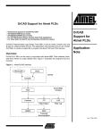
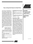
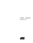
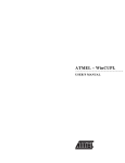
CMOS PLD Using the Programmable Polarity Control The output programmable polarity control in PLDs brings efficiency in logic reduction and control of output polarity to the customers. Unfortunately, it also brings confusion to customers who are not familiar with the software syntax to properly configure the output polarity. This application note shows the proper usage of the popular ABEL and CUPL syntax to configure the output polarity of Atmel PLDs. Configuring Polarity with (4.x or higher) Atmel-ABEL of the other, either one is logically correct. Case 2: (Combinatorial - ISTYPE ’BUFFER’) Declaration OUT pin 14 ISTYPE ’buffer’; “assume 14 is an I/O pin equations OUT = A # B # C; In this case, the compiler will only consider the on-set because the ISTYPE ’BUFFER’ overrides the automatic selection. The outcome is represented by Figure 1. The optimization level best suited for Atmel PLDs is the default option – reduce by pin and auto polarity. This reduction level will take advantage of the polarity control when performing logic optimization one output at a time. This will override the ISTYPE ’NEG’ and ISTYPE ’POS’ used in ABEL 3.x source files (check the user manual on backward compatibility for detail). Therefore, the ’NEG’ and ’POS’ extensions are not recommended. Case 3a: (Combinatorial - ISTYPE ’INVERT’) The following examples have A, B, and C defined as inputs and OUT or !OUT as the output: Case 3b: (Combinatorial - no ISTYPE definition) Case 1: (Combinatorial - no ISTYPE definition or ISTYPE ’COM’) Declaration OUT pin 14; “assume 14 is an I/O pin equations OUT = A # B # C; In this case, the compiler will consider both Figure 1 (on-set) and Figure 2 (offset) and automatically select the implementation requiring fewer product terms for the same function. The outcome is represented by Figure 2. Since Figures 1 and 2 are each DeMorgan equivalent Erasable Programmable Logic Device Application Note Using the Programmable Polarity Control Declaration OUT pin 14 ISTYPE ’invert’; “assume 14 is an I/O pin equations OUT = A # B # C; In this case, the compiler will only consider Figure 2 (off-set) because the ISTYPE ’INVERT’ overrides the automatic selection. The outcome is represented by Figure 2. Declaration !OUT pin 14; “assume 14 is an I/O pin equations OUT = A # B # C; The compiler would pick Figure 3 to implement the logic because it takes fewer product terms. In ABEL documentation, signals on the right side of the equation do not have “!” as part of their names. ABEL preprocessor will remove the “!” from the pin name on the right side of the equation and replace all references on the left side with an additional “!”. Logically, this does not change any(continued) 0424B 8-73 Configuring Polarity with Atmel-ABEL (4.x or higher) (Continued) thing. It does, however, tend to create some confusion reading the .DOC files. In the source file, the user should still use whatever pin name is given in the declaration section. All references to the pin or .FB feedbacks will be adjusted by the software to reflect the changes automatically. Case 3c: (Combinatorial - ISTYPE ’INVERT’) Declaration !OUT pin 14 ISTYPE ’invert’; “assume 14 is an I/O pin equations OUT = A # B # C; The compiler would pick Figure 4 to implement the logic. For combinatorial equations, it is best to leave out the ISTYPE statement and let the optimizer choose the best DeMorgan equivalent implementation. Figure 1. Figure 2. Figure 3. Figure 4. Note: 1. The “buffer” or “invert” ISTYPE has no effect for combinatorial outputs in Atmel-ABEL 5.x. Case 4: (Registered - no ISTYPE definition) Beware! Case 5: (Registered - ISTYPE ’BUFFER’) Declaration OUT pin 14; “assume 14 is an I/O pin equations OUT := A # B # C; OUT.c = CLK; OUT.ar = AR1; Declaration OUT pin 14 ISTYPE ’buffer’; “assume 14 is an I/O pin equations OUT := A # B # C; OUT.c = CLK; OUT.ar = AR1; The pre-processor will warn you for not specifying the ISTYPE of the output. In this case, the compiler will use the fewest product term implementation (Figure 6). This might not be what the user is expecting. (1) The compiler will only consider Figure 5 (on-set) because the ISTYPE ’BUFFER’ overrides the automatic selection. Note: 1. Figure 5 and Figure 6 do not produce identical results. In Figure 5, at power up or after a reset, the output pin appears to be a “0.” Unlike Figure 5, Figure 6 powers up and resets to a “1” on the output. Preset and preload behave differently between the two as well. In some applications where power-up state of a register is not important and it never resets or presets, Figures 5 and 6 become identical. Only in this case are they logically equivalent. When using a registered output, always specify the ISTYPE desired. 8-74 CMOS PLD Case 6: (Registered - ISTYPE ’INVERT’) Be careful! Declaration OUT pin 14 ISTYPE ’invert’; “assume 14 is an I/O pin equations OUT := A # B # C; OUT.c = CLK; OUT.ar = AR1; The compiler will only consider Figure 6 (off-set) because the ISTYPE ’INVERT’ overrides the automatic selection (see Note 1 on Case 4). (continued) CMOS PLD Configuring Polarity with Atmel-ABEL (4.x or higher) (Continued) Case 7: (Registered - ISTYPE ’BUFFER’) Confusing – don’t use. Declaration !OUT pin 14 ISTYPE ’buffer’; “assume 14 is an I/O pin equations OUT := A # B # C; OUT.c = CLK; OUT.ar = AR1; The compiler will only consider Figure 7 (on-set) because the ISTYPE ’BUFFER’ overrides the automatic selection. Case 8: (Registered - ISTYPE ’INVERT’) Declaration !OUT pin 14 ISTYPE ’invert’; “assume 14 is an I/O pin equations OUT := A # B # C; OUT.c = CLK; OUT.ar = AR1; The compiler will only consider Figure 8 (off-set) because the ISTYPE ’INVERT’ overrides the automatic selection. In ABEL documentation, the pin name will be stripped of the “!”. It will replace all pin name references with an additional “!” on the right-hand side of the equations. Figure 5. Figure 6. Figure 7. Figure 8. Note: 1. For cases 4 through 8, if you used the dot extension (.D, .T, etc) in your output equations (like “Out.d = A # B # C;”), then the compiler will only consider the “Buffer” condition (on-set) even when the “invert” ISTYPE is specified for these outputs. The “Buffer” condition is also only considered when you specify REG_T, REG_G, REG_JK or REG_SR in your ISTYPE statement. 8-75 Configuring Polarity with Internal Nodes Internal nodes do not have programmable polarity control. Do not use any ISTYPE extensions. Think of it as “positive logic” only. Case 1: (Figure 9) Declaration OUT node 50; “assume 50 is an internal node equations OUT = A # B # C; Figure 9. Figure 10. 8-76 CMOS PLD Case 2: (Figure 10) Declaration OUT node 50; “assume 50 is an internal node equations OUT.d = A # B # C; OUT.c = CLK; OUT.ar = AR1; The above example is the only legal method of assigning equations to nodes. CMOS PLD Configuring Polarity with CUPL Note that CUPL has no “buffer/invert” ISTYPE statement. Output polarity is controlled by pin declaration versus equation polarity. Case 1: (Combinatorial) PIN 14 = OUTC; /* assume 14 is an I/O pin */ OUTC = A # B # C; The compiler would choose Figure 11. It does not choose the better DeMorgan equivalent automatically. If your equation does not fit, you should check to see if you can rewrite it as: PIN 14 = OUTC; !OUTC = !A & !B & !C; Case 2: (Combinatorial) PIN 14 = !OUTC; /* assume 14 is an I/O pin */ OUTC = A # B # C; The compiler would choose Figure 12. The difference between the pin declaration (!OUTC) and the equation name (OUTC) tells the compiler to have an inverter on the output and to implement the equations as specified by the equation. Case 3: (Registered) PIN 14 = OUTC; /* assume 14 is an I/O pin */ OUTC.d = A # B # C; OUTC.ck = CLK; The compiler would choose Figure 13. The pin name and the equation name are identical; the compiler does not place an inverter on the output. Case 4: (Registered) PIN 14 = !OUTC; /* assume 14 is an I/O pin */ OUTC.d = A # B # C; OUTC.ck = CLK; The compiler would choose Figure 14. The difference between the pin declaration (!OUTC) and the equation name (OUTC) tells the compiler to have an inverter on the output and to implement the equations as specified by the equation. CUPL maintains the !OUTC on the pinout diagram documentation and equation name OUTC in the reduced equation portion of the documentation. Both ABEL and CUPL conventions for handling signal polarity have drawn praises and criticisms. Help on the software is readily available from Data I/O Corporation (ABEL), Logical Devices, Incorporated (CUPL), and Atmel. Don’t hesitate to call for help. Figure 11. Figure 12. Figure 13. Figure 14. 8-77 Polarity Control for Atmel’s Flash 16V8 and 20V8 Devices This section discusses the ABEL and CUPL syntax for devices with fixed inverting output buffers and output polarity control such as Atmel’s Flash 16V8 and 20V8 devices. (1) Configuring Polarity with ABEL The following examples have A, B, and C defined as inputs and OUT as the output. Only ISTYPE ’Com’ for combinatorial or ISTYPE ’Reg’ for registered outputs should be used. (2) This allows ABEL to optimize the logic to generate an implementation with the fewest number of product terms. Case 1: (Combinatorial - High-True Output) Declaration OUT pin 14 ISTYPE ’Com’; Equations OUT = A # B # C; The compiler will pick Figure 15 to implement the logic. To make the output high-true, the compiler will invert the logic twice to obtain correct output polarity. Case 1a: (Combinatorial - Low-True Output) Declaration OUT pin 14 ISTYPE ’Com’; Equations !OUT = A # B # C; “Equivalent to Out = !A & !B & !C The compiler will pick Figure 16 to implement the logic. To make the output low-true, put a “!” in front of OUT in the logic equations section. The compiler will invert the logic three times to obtain the correct output polarity. Case 2: (Registered - High-true Output) Declaration OUT pin 14 ISTYPE ’Reg’; “The ’Reg’ ISTYPE should be used Equations Out := A # B # C ; “’:=’ is required to specify a Registered Output OUT.clk = clk; OUT.ar = AR; The compiler will choose Figure 17 to implement the logic. To make the output high-true, the compiler will invert the logic twice to obtain the correct output polarity. Figure 15. Figure 16. Figure 17. Figure 18. Notes: 1. Because of the fixed inverting outputs, all flip-flops for these devices will reset during power up or through Asynchronous Reset logic to a “High” or “1" state regardless or how the logic is implemented. 8-78 CMOS PLD 2. The compiler will not compile correctly if the ISTYPE such as ’Reg_D’, ’Buffer’, ’Invert’, ’Pos’ or ’Neg’ are used. CMOS PLD Case 2a: (Registered - Low-True Output) Case 1a: (Combinatorial - Active Low) Declaration OUT pin 14 ISTYPE ’Reg’; Equations !OUT := A # B # C; “Equivalent to OUT.d = !A & !B & !C OUT.clk = clk; OUT.ar = AR; pin 14 = !OUT OUT = A # B # C; The compiler will choose Figure 18 to implement the logic. To make the output low-true, put a “!” in front of OUT in the logic equations section. The compiler will invert the logic three times to obtain the correct output polarity. Configuring Polarity with CUPL Polarity is controlled in CUPL at the pin declaration, just like other Atmel PLD and CPLD devices. CUPL will optimize the logic equations to match the pin polarity. (1) Case 1: (Combinatorial - Active High) Pin 14 = OUT OUT = A # B # C; The compiler will choose Figure 19 to implement the logic. The pin polarity on the pin declaration indicates an active high output, CUPL will invert the logic twice to obtain the correct output polarity. The compiler will choose figure 20 to implement the logic. The “!” on the OUT pin declaration indicates that an active low output is required. CUPL will invert the logic once to obtain the correct output polarity. Case 2: (registered - Active High) Pin 14 = Out; OUT.d = A # B # C; OUT.ck = clk; OUT.ar = AR; The compiler will choose Figure 21 to implement the logic. CUPL will invert the logic twice to obtain the correct output polarity. Case 2a: (Registered - Active Low) Pin 14 = !Out; OUT.d = A # B # C; OUT.ck = clk; OUT.ar = AR; The compiler will choose Figure 22 to implement the logic. The “!” on the OUT pin declaration indicates that an active low output is required. CUPL will invert the logic once to obtain the correct output polarity. Figure 19. Figure 20. Figure 21. Figure 22. Note: 1. Because of the fixed inverting outputs, all flip-flops for these devices will reset during power up or through Asynchronous Reset logic to a “High” or “1" state regardless or how the logic is implemented. 8-79