1
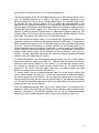
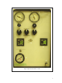
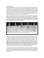
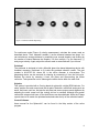
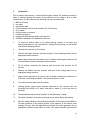
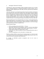
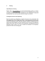
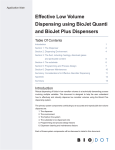
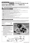
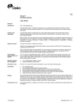
User’s Manual for SphereJet MicroFab Technologies Inc V 1.0 1 Contents 1 2 Introduction ............................................................................................................................. 3 Installation............................................................................................................................... 4 Environment ............................................................................................................................... 4 Enclosure.................................................................................................................................... 4 Cables & External Electronics ................................................................................................. 5 JetDriveIII .................................................................................................................................. 5 Computer .................................................................................................................................... 5 Pneumatics ................................................................................................................................. 5 Camera & Strobe........................................................................................................................ 7 Printhead..................................................................................................................................... 9 Stirplate....................................................................................................................................... 9 3 Preparation ........................................................................................................................... 10 4. Operation .............................................................................................................................. 12 4.1 Drop-on-Demand Mode (DOD) ...................................................................................... 12 4.2 Pressure Assisted-DOD Mode (PA-DOD)..................................................................... 12 4.3 Continuous Dispensing Mode....................................................................................... 13 5 Microsphere Collection & Processing ................................................................................... 14 6 Cleaning ................................................................................................................................ 15 Inkjet Dispenser cleaning........................................................................................................ 15 Cleaning the reservoir after dispensing ................................................................................ 15 2 1 Introduction MicroFab’s SphereJet system is an inkjet-based machine designed for experimental, small batch, microsphere production. Incorporating the principles of solvent-extraction microsphere formation, SphereJet user’s can select from drop-on-demand, pressure assisted drop-on-demand, and continuous mode inkjet dispensing to fabricate microspheres. Because the users can select from myriad dispensing and extraction fluids, combined with 3 types of dispensing methods, there are many opportunities to create customized microspheres for their independent applications. MicroFab’s SphereJet system allows the user to determine the best methods and materials for small batch, experimental microsphere production, saving the time and expense of large trials. 3 Figure 1 MicroFab’s SphereJet system 2 Installation Environment Cleanliness is extremely important to the successful operation of an inkjet dispenser. Consider the installation environment carefully before placing your SphereJet station. Dust or other particulate matter (skin cells, clothing lint, hair, etc.,) in the air can contaminate dispensing fluids or the collection beaker. Protective gloves are recommended when handling devices, reservoir, collection vessel and anything containing or in contact with solvents. Enclosure Inside the SphereJet enclosure resides the stir plate, Z-axis gantry and stage, printhead fixture, and reservoir (Figure 1). Be certain that the station enclosure is placed upon a table top that can hold up to 150lbs. Also remember to provide enough space to accommodate the computer system, pneumatics box, external electronics, and drive electronics. The SphereJet enclosure is outfitted with a 4” diameter closeable ventilation port. This port should be used whenever volatile (lighter or heavier than air) solvents are used in the dispensing fluid or collection vessel. Be certain adequate ventilation is available 4 at your facility. Ensure local compliance for venting vapors to atmosphere. Always keep the cabinet doors closed unless necessary to access components inside the enclosure cabinet. This will lower contamination and provide some vapor retention. Keep in mind that the SphereJet system is not air or fluid tight. Use ventilation whenever necessary and be aware of potential hazards from spilling solvents in the workspace. Cables & External Electronics All cables that connect the components of the SphereJet system are connected at MicroFab and securely bundled. Bundling helps clear the workspace of clutter and prevents the cables from being trapped by the motion of the Z-axis travel. Removing or modifying the cable bundling may create interference with this travel. Cables that are not connected out-of-the-box will be clearly labeled on how to connect them. SphereJet also uses external USB-based electronics to enhance functions while reducing the overall footprint of the station. Like the cables, these components are affixed to one another at MicroFab and should be treated as one component when considering placement. Modifying this bundling may interfere with component function. Connections between the components require placement in proximity of one another. If this conflicts with the workspace layout, contact MicroFab Technologies Inc. for longer cables. JetDriveIII The dispensing software installed on the computer controls MicroFab’s JetDriveIII drive electronics box. This component sends the electrical waveform required to drive the inkjet dispenser. Output from the drive electronics feeds to the dispenser and strobe LED that illuminates droplets from the dispenser. The JetDriveIII can be safely placed on top of the pneumatics box to conserve workspace when installing the system. Computer SphereJet is provided with a laptop adequate for running the drive and image software. Cable connections between the computer and other components are bundled at MicroFab and should not be modified. If modification is required for the workspace, contact MicroFab Technologies Inc. All required software to run the system and vision components are pre-installed. Rescue CD is also provided. Pneumatics MicroFab’s pneumatics box included in the SphereJet system provides pressure and vacuum control to the inkjet dispenser. This controller is capable of pressure up to 100psi for continuous dispensing applications. As shown in Figure 2, the pneumatics controller has analog gauges for displaying purge pressure (1) and vacuum (2) each with off/on knob controllers (3 & 4, respectively), a backpressure/purge selector switch (6), two Keyence digital pressure gauges (8 & 10) displaying the pressure or vacuum value sent to the reservoir, a Low/High toggle switch 5 (9) to switch, and a Fairchild valve (11) to control backpressure. The Keyence gauge on the left (8) displays pressure up to 30psi and the gauge on the right (10) displays pressure up to 100psi. The value of pressure displayed on the Keyence gauges (8 & 10) is in inHg. 1.0inHg equals 0.49psi. The Low/High toggle switch (9) between the two Keyence gauges (8 & 10) diverts the pressure/vacuum feed between the two gauges for measuring. If you exceed the pressure threshold of the low pressure gauge (8) switch the Low/High toggle switch (9) to the right to display pressure through the high pressure gauge (10). Fine control of pressure or vacuum to the reservoir is made through the Fairchild valve (11) below the left Keyence gauge (8). The Fairchild valve (11) can move through vacuum and pressure settings between -14.0psi and 100psi. (The strobe delay switch (12) is unused in this setup.) When the backpressure/purge switch (6) is set toward the “backpressure” position, the pressure or vacuum is exclusively controlled through the Fairchild valve (11) and read on either of the Keyence gauges (8 & 10) depending upon how the Low/High toggle switch (9) is set. The amount of pressure or vacuum available for the Fairchild valve (11) to control depends upon the total amount of pressure or vacuum entering the pneumatics console. While the backpressure/purge switch (6) is set to “backpressure”, the pressure switch (5) and vacuum switch (6) are disabled, and will not activate if set to the “on” position. Typically, dispensing experiments are performed with the backpressure/purge switch (6) set to the “backpressure” position. To purge with pressure, turn the backpressure/purge switch (6) to the “purge” position and turn the pressure switch (5) toward “on”. This will send the amount of pressure indicated in the pressure gauge (1) to the reservoir. You can alter the pressure sent to the reservoir by adjusting the purge pressure control knob (3). The digital Keyence gauge (8 or 10) that the Low/High toggle switch (9) is set toward displays the exact amount of purging pressure sent into the reservoir. To vacuum purge, turn the backpressure/purge switch (6) to the “purge” position and turn the vacuum switch (7) toward “on”. This will send the amount of vacuum indicated in the vacuum gauge (2) to the reservoir. You can adjust the vacuum sent to the reservoir during a purge by turning the purge vacuum control knob (4). The digital Keyence gauge (8 or 10) that the Low/High toggle switch (9) is set toward displays the exact amount of purging vacuum sent into the reservoir When the backpressure/purge switch (6) is set to “backpressure”, the positions of the switches (5) and (7) does not have any influence on the pressure/vacuum applied to the reservoir (controlled by the Fairchild regulator). Do not set the backpressure/purge switch (6) to “purge” with the pressure switch (5) and vacuum switch (7) set to “on”. 6 Figure 2 SphereJet Pneumatics Console 7 Camera & Strobe The camera and strobe are designed to be in line with the tip of the dispensing device. The strobe is fixed in its position. The camera can be adjusted for angle and Y-axis adjustment via a setscrew on the camera armature. A focus adjustment is also provided on the camera tube. Because the camera may have moved during shipment, be sure the tip of the dispenser is within the camera’s field of view. Although the camera setup is designed to view the dispenser tip in air during setup, you may be able to view submerged dispensing in the catch vessel. This depends on the optical properties of the catch fluid and may require moving the vessel to focus the view. Each time the dispenser is activated, a signal is also sent to the strobe LED positioned behind the dispenser on the Z-axis. This illuminates the droplets coming from the device. The strobe delay, located in the main program screen or the black dial on the JetDriveIII controller, can be adjusted to increase or decrease the delay between the device trigger and the strobe trigger. Increasing the strobe delay shows the progression of the droplets from the dispenser along their trajectory (Figure 3). Figure 3 Progression of a droplet from the device as the strobe delay increases Creating a screen scale allows making drop size and velocity measurements. To create a screen scale, measure the diameter of the device tip in microns, or capture an image of a micron scale slide in the camera view. Install the device within the field of view of the camera, capture an image, and measure the device tip with a caliper or other measuring tool. Divide the value of the actual diameter with the value of the screen diameter; this gives the screen scale value. When you dispense a droplet, measure its screen diameter and multiply it by the screen scale value, and you will get an approximation of the diameter of the droplet. Note that the observed diameter of the drop decreases with the frequency as there is more light collected by the camera and the drops appear smaller due to diffraction. Also, changing the relative position between the camera and the LED could result in changes in the measured drop value. To calculate drop velocity in drop on demand mode, measure the distance a droplet on the screen moves after increasing the strobe delay a fixed number of microseconds. This measurement creates a distance/time value. Multiply the distance traveled by the screen scale for actual distance, this provides m/s. You can convert to meters/second if you choose. 8 Figure 4 Continuous Mode dispensing For continuous mode (Figure 4) velocity measurement, calculate the screen scale as described above. Then, measure Lambda () as the distance between two drops. You can calculate an average distance by measuring over several droplets, and dividing by the number of interval between the droplets. You then multiply by the frequency () and you get velocity. Again, adjust the subunit scale to meters/second if you choose. Printhead The printhead is designed to hold a Microfab glass tube based dispensing device with threaded connector, positioned to fit inside the provided collection vessel. The part number is MJ-AT-01-XX, where XX is the orifice diameter in micrometers. The dispensing device can be removed for cleaning by unscrewing it from the fluid union. Replace the device by screwing it back into place and reconnecting the Molex connector. Take precaution not to submerge the entire device within the catch fluid. Stirplate This system is provided with a Corning brand stir plate with a digital RPM indicator. For setup, position the catch vessel onto the stir plate, filled with a catch fluid analog such as water, and insert a stir bar. Activate the stir plate and ensure proper vessel alignment by adjusting the catch vessel until the turning stir bar is centered. Although this system comes with octagonal stir bars, off the shelf stirrers can be substituted. Move the Z-stage up and down to be certain the printhead and strobe clear the lip of the collection beaker. Control Software Users manual for the SphereJet can be found in the Help section of the active program. 9 3 Preparation Prior to loading the reservoir, it should be thoroughly cleaned. All measures should be taken to reduce exposing the interior of the reservoir and it’s tubing to dust or other contaminants. For this procedure the following items are recommended: 1. 2. 3. 4. 5. 6. 7. 8. 9. MilliQ or DI water Hot water A sonication bath Critical cleaning solution (such as Micro-90; Cole Parmer) A 1L beaker Dust free area or container Powder-free gloves Isopropyl Alcohol squeeze bottle with clean IPA Ventilation attached to the SphereJet enclosure 1. To clean the beaker make a 1% critical cleaning solution in hot water and immerse the reservoir, cap, and Minstac fittings with the tubing, into the beaker filled with hot cleaning solution. 2. Sonicate the reservoir for 30 minutes. 3. Remove the beaker from the sonicator and pour off the cleaning solution into an appropriate waste container. 4. Apply copious amounts of hot water to the 1L beaker containing the reservoir until no more bubbles from the cleaning solution are seen. 5. Fill the beaker containing the reservoir with hot water and sonicate for 30 minutes. 6. Remove the beaker from the sonicator and pour off the rinsing water into an appropriate waste container. 7. Apply copious amounts of hot water to the 1L beaker containing the reservoir for 5 minutes, overflowing the beaker. This should be done in a sink. 8. Pour off the excess water from the beaker. 9. Wearing gloves, remove each cleaned component of the reservoir and rise thoroughly with MilliQ or DI water, and place it aside in a dust free area or container. 10. Reassemble the reservoir and reinstall it on the SphereJet station. 11. Be certain ventilation is functioning through the enclosure before proceeding. 12. With the tubing attached to the inkjet device holder, fill the reservoir with MilliQ or DI water (because of the relative position of the reservoir to the device some leakage will occur from the inkjet device) and flush the entire apparatus into an appropriate container using 500mL of water. The system should be pressurized 10 to 10psi. 13. Repeat this process using IPA 14. Purge the IPA vapor using 10psi until no odor is detected and no droplets are seen at the inkjet device Minstac fitting. Preparing the reservoir and device for dispensing Before loading the reservoir with the dispensing solvent, the reservoir, connections, tubing, and dispensing device should be flushed with the primary solvent of the dispensing solution. Please contact MicroFab Technologies Inc., with any questions. 11 4. Operation 4.1 Drop-on-Demand Mode (DOD) In drop on demand mode, hydrostatic pressure introduced by a fluid level being higher than the orifice and backpressure (low vacuum) is balanced to maintain the fluid meniscus at the dispenser orifice. Here, pressure from the piezoelectric actuator is used to generate droplets. One droplet is ejected per trigger of the device, as controlled by the dispensing program. Because the reservoir is positioned above the level of the orifice, a slight vacuum is needed in drop on demand mode to prevent dripping at the orifice. Dispensing is accomplished by entering a waveform parameter in the software that will eject the droplet. Each fluid has a different set of waveform parameters that is established through an iterative procedure. Set the selector switch between the Keyence gauges to the left for low-pressure management, and adjust the Fairchild regulator as necessary. As a starting point, set the begin with a unipolar waveform whose rise and fall time is 3.0s, dwell time of 30s, voltage of 30V, and frequency of 240Hz. Set the Fairchild regulator to 0.0kPa or with enough vacuum to prevent dripping from the orifice. Collecting microspheres depends upon the interaction between the dispensing and catch fluid, and is determined through experimentation. Drop on demand microsphere dispensing is typically done with the dispenser tip in air over the catch fluid. 4.2 Pressure-Assisted-DOD Mode (PA-DOD) In pressure-assisted drop on demand mode, a slight positive pressure is applied to the reservoir during dispensing. This pressure (up to 6 psi in previous work) will aid drop ejection and throughput without significantly increasing the drop diameter. Here, activate the dispensing waveform and apply pressure simultaneously, with the selector between the Keyence gauges set to the left. Adjust the waveform and pressure input (Fairchild regulator) until the desired drop diameter is found in air. Once you have the desired output, submerge the tip into the catch fluid through the program if this is compatible with your experimental setup. Experimentation is required to match the microsphere output with initial droplet size in air. 12 4.3 Continuous Dispensing Mode Continuous mode dispensing uses the disruption created through the active piezo actuator in the device to breakup a pressurized stream of fluid. This leads to a larger drop when compared to drop-on-demand, typically double the orifice diameter. This system provides pressure up to 100psi. In this paradigm, high pressure and high frequency triggering combine to create a stream of uniform droplets from the dispenser tip. This technique is best suited for high throughput applications. Set the selector switch that is between the Keyence gauges to the right for high pressure. Turn the Fairchild regulator until the desired pressure is achieved and activate the dispensing device. Typically, high frequency sinusoidal waves are used for continuous mode dispensing. Once you create the desired output, submerge the tip and begin collecting. This process will require experimentation because no single technique can cover all possible dispensing and catch fluid pairings. Supplemental information on the theory of continuous mode dispensing is provided. There is shrinkage in the spheres during the solvent extraction so an iterative process has to be used to produce the desired size. As a first order approximation, the drop size (before fluid extraction) is about twice the orifice diameter. Shrinking depends on the solvent used in the solution for the microspheres and the solvent extraction and is typically in the range of 10-20%. Use these formulas to select an orifice size. Additional adjustment of the drop size is provided through the control parameters: applied pressure and perturbation frequency. The first step is to setup the dispensing in air. Increase the Vdrop pressure and the sinusoidal d perturbation to where the fluid leaves the orifice as seen in Figure 5. Measure the distance between droplets or “bumps” to determine the wavelength (For an accurate Figure 5. Continuous ink-jet and parameters. measurement measure the distance over several intervals (drops) and divide by their number. The distance should be around 4.5d, where d is the orifice diameter. If the wavelength is smaller, increase the pressure to get to the desired value. If the wavelength is larger, decrease the applied pressure. Immerse the dispenser in the solvent extraction bath and apply the pressure and frequency determined above. Process the spheres as described in the next section and measure the final diameter. Adjust the pressure and frequency accordingly: - To increase the size of the final microspheres reduce the frequency while maintaining the pressure constant or increase the pressure at constant frequency - To reduce the size of the final microsphere change the parameters in the opposite direction 13 5 Microsphere Collection & Processing The SphereJet system was designed for batch microsphere collection into a 1L beaker using a submerged dispenser tip. Dispensing parameters including waveform, type of dispensing method, dispensing and catch fluids, and stirrer speed must be determined experimentally. In previous experiments, once dispensing parameters have been selected, the dispenser tip is lowered into the catch fluid for a period of time. Microsphere formation depends upon the thermodynamic interaction between the dispensed solution and the catch fluid As the microsphere forms inside the catch fluid, the solvent used in the dispensed solution exchanges position with the catch fluid, solidifying the microsphere. Formed microspheres are allowed to stir for a period of time, determined experimentally, then removed via filtration, or liquid nitrogen freezing and sublimation of the frozen catch fluid. Dried microspheres have been manipulated with a fine brush, or sharp edged laboratory spatula. Static electricity, or the presence of charge on collection or storage vessels will impair manipulation. Drying the microspheres through sublimation in their final storage vessel can eliminate the need to manipulate them. Sample Collection Regime Stir the microspheres in the catch fluid for 1 – 2 hours Stop stirring, and allow the microspheres to settle for 15 minutes, then withdraw 800mL of catch fluid, and replace it with DI water. Repeat stirring for 15 minutes. Repeat stirring, settling, and DI water rinses 3-5 times. Vacuum filter the rinsed microspheres through an appropriately sized screen or filter paper. Allow the microspheres to air dry, then place in a storage vessel. Collection methods will differ, however the most important aspect is to remove as much of the polymer solvent from the microspheres as possible before they are dried. This removal may also be completed through lyophylization. An example of MicroFab’s www.microfab.com. previous microsphere work can be seen at 14 6 Cleaning Inkjet Dispenser cleaning Please refer to www.microfab.com for the MJ device-cleaning guide for common cleaning procedures. If the dissolved solid has dried onto the dispensing device, rinsing the glass tip with the solvent might resolubilize the solid. Remember to follow the warnings listed in the online document to prevent damage to your device. Cleaning the reservoir after dispensing Removing residues once dispensing is complete will prevent cross contamination with future experiments. Before cleaning the reservoir, its component fluid connections, and the dispenser device in the outline above, flush all the components with the primary solvent of the dispensing solution. Be certain adequate ventilation is available and insure proper waste solvent disposal. Flush the components until no remnant of the dispensing solution can be seen. Once the reservoir, fluid components, and dispenser are free of dispensing solution residue, they can be washed as described in the Preparation procedure and MJ device-cleaning guide. 15