1
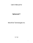
Application Note
Effective Low Volume
Dispensing using BioJet Quanti
and BioJet Plus Dispensers
Table Of Contents
Introduction
1
Section 1: The Dispenser
2
Section 2: Dispensing Environment
4
Section 3: The fluid, including rheology, dissolved gases
and particulate content
5
Section 4: The substrate
6
Section 5: Programming and Process Design
7
Section 6: Dispenser Maintenance
10
Summary: Considerations for Effective Nanoliter Dispensing
11
Appendix
12
Summary
15
Introduction
Robust dispensing of fluids in low nanoliter volumes is a technically demanding process
involving multiple variables. This document is designed to help the user understand
how to effectively and robustly dispense low nanoliter volumes using the BioJet Plus
dispensing system.
The primary system components contributing to an accurate and reproducible low volume
dispense are:
1. The dispenser
2. The environment
3. The fluids in the system
4. The substrate to be dispensed onto
5. Programming and process design factors
6. Dispenser cleaning and maintenance factors
Each of these system components will be discussed in detail in this document.
Section 1: The Dispenser
through the tip orifice and ejects as a drop (or stream
The BioJet Plus technology combines the high-resolution
displacement capabilities of a syringe pump with a highspeed micro solenoid valve. This combination permits the
non-contact dispensing of nanoliter volumes.
if the amount of fluid is large). One valve actuation
results in one drop.
The key to a correct volume being dispensed in a given drop
from the BioJet Plus system is the steady-state pressure
(SSP) in the dispensing system. This pressure has several
important features:
BioJet Plus Valve
TM
• It is achieved by the displacement of fluid by the
BioJet Plus
Valve
syringe pump
TM
• The SSP is displacement (drop size) dependent,
increasing with increasing displacement (drop size)
Ceramic
Sensor
Cards
Figure 1 - BioJet Plus Dispensing System
In a typical dispensing system, 4 to 8 of these syringe/
solenoid channels are placed together. Two modes of liquid
handling are possible: Continuous (bulk) dispensing and
aspirate/dispense.
Continuous dispensing involves pulling reagent or solvent
from a reservoir into the syringe and then dispensing it
through the micro solenoid valve. Filling the system with
a backing fluid, dipping the tip of the valve into a sample,
withdrawing the syringe to aspirate the sample, and then
dispensing the aspirated sample accomplishes Aspirate/
dispense.
The BioJet Plus™ dot dispensing system is a hydraulically
driven system that requires a fluid medium to be present
from the syringe to the microsolenoid BioJet Plus™ valve.
The dispensing process involves the following steps:
1) The syringe is displaced a given amount
2) The valve is opened for a short period of time
(milliseconds)
3) Fluid is released from the valve and travels to the tip
4) The fluid increases its linear velocity as it passes
Effective Low Volume Dispensing using BioJet Quanti and BioJet Plus Dispensers
• The SSP is determined by the system compliance,
which is dominated by entrapped air bubbles.
• Once the SSP is established, the amount of fluid
displaced by the syringe pump will equal the amount
dispensed
The BioJet Plus™ dot dispensing system can be modeled
as an electrical circuit with the pressure acting as the
voltage, the flow rate as the current, the system compliance
as capacitive elements, the valve, tip, and feed lines as
resistive elements, and the valve as a switch. This model
shows the syringe pump as a current source, which provides
an advantage over a pressure source (e.g. gas pressure) in
that any changes in resistance will not affect the flow rate.
In contrast a pressure source will be affected by changes in
resistance in the system.
Factors Affecting the Dispense Volume
The model described above shows the fluidic circuit
possessing a feedback loop, which can be used to achieve
the SSP. Once the SSP has been achieved, the volume
displaced will equal the volume dispensed.
The SSP is achieved by first pre-pressurizing the system by
displacing an experimentally determined volume using the
www.biodot.com
Application Note xxxxxx
syringe pump. Usually this pre-pressure is slightly higher
vent, which opens the microsolenoid valve without displacing
than the required system pressure and requires several
any fluid. When sample is aspirated, the syringe pump draws
pre-dispenses at the desired volume to reach steady
fluid through the tip orifice. The resistance to flow from the tip
state pressure, whereby the desired dispense volume is
and valve creates a negative pressure, which must first be
dispensed.
overcome to achieve a steady state pressure.
Several factors influence the achievement and maintenance
As with priming, venting the system can bring the system to
of the SSP and the desired dispense volume:
a known (zero/ambient) pressure, from which the SSP can
be applied (Note: venting is typically done with tips in the
Priming
sample to prevent the introduction of air).
The Prime is used to initialize the syringe pumps and fill
the syringe pumps, microsolenoid BioJet Plus valves of
the dispense head, and connecting tubing with fluid from
The SSP during a prime/aspirate/dispense cycle is shown
the reservoir(s). The reservoir fluid is either system fluid for
schematically below:
aspirate/dispense of reagent, or sample fluid for continuous
(line or dot) dispensing.
When the dispense system is primed, several hundred micro
liters of fluid are dispensed as a stream. The resistance to
flow caused by the valve and tip orifice causes the pressure
within the system to become higher than desired for SSP. To
achieve SSP, one must first vent the valves, which involves
opening the valves without displacing fluid. This brings the
system to ambient (zero) pressure and from this point; the
SSP pressure can be achieved.
Aspiration
The aspirate function draws sample from a reservoir,
usually a micro-well plate, into the tip of the dispense head.
To perform an aspirate, several parameters must be set.
These parameters are set by using Syringe Speed and
Gas Bubbles
Gas bubbles can occur in the dispensing system for
Channel Parameter actions. The syringe speed controls
multiple reasons, including primarily leaks and dissolved
the speed of the syringe pump dispensers. In general,
gases in the fluid. The major effect of bubbles is to change
slow syringe speeds are used for aspiration to prevent a
the system compliance, which can affect drop formation.
large vacuum from being developed which can result in the
Input will still equal output but the fluid will collect on the
development of bubbles in the system.
dispense tip rather than eject as a full drop. This can cause
During the normal aspiration process, a slight negative pressure
variation in dispensed volumes and eventually cessation of
is produced. This negative pressure is relieved by performing a
dispensing.
www.biodot.com
3
Bubbles can be removed by purging the system with
For a dispense system at SSP, the proper open time will
isopropanol and using degassed solvents as well as the
result in a displaced volume equal to the dispensed volume.
system fluid.
If the open time is too short, then over time pressure will
build beyond the SSP. If the open time is too long, the SSP
Tip Effects
will be dissipated eventually resulting in drops not being
Condensation of liquid on the dispense tips can lead to
ejected from the tip.
loss of control of dispense volumes due to the interaction
of ejected drops with resident fluids near the tip orifice.
The open time is the approximate time required for the
This effect can be reduced and/or eliminated by vacuum
fluid to move though the valve. Thus open time increases
drying of the tips at appropriate times during the dispense
with increasing drop size and increasing viscosity. A list
cycle. Vacuum drying the tips is especially important when
of appropriate on-times is contained in the dispenser
dispensing for long periods of time. Tip orifice size is also
manual.
of critical importance. Smaller drop sizes require smaller
properties of the fluid and the particulate content of the fluid
Section 2: Dispensing
Environment
to be dispensed, as smaller orifices clog more easily than
Many dispensing applications require careful control of the
larger orifices.
dispensing environment. This can entail control of :
orifice sizes for proper drop formation. The smaller orifice
size must, however, be balanced against the rheological
• Humidity
Syringe Speed
• Static electricity
Syringe speed is the speed of displacement of the fluid in
• Partial pressure of solvents or noble gases
the syringe pump. For dispensing, the syringe speed has
• Airborne particulates
little if any affect on the SSP. For priming, the syringe speed
The use of environmental enclosures around machines
will effect the pressure build-up and at very high speeds,
can be critical in ensuring proper and continuous operation
may cause too much pressure and result in leaking. For
of the machine. The use of controlled, elevated humidity
aspiration, slow speeds are best to prevent excessive
environments can be important in aspirate and dispense
negative pressures being generated, which could also lead
applications where open reservoirs of small volumes of
to out-gassing from the fluids.
aqueous reagents are used as the source for dispensing.
Slightly elevated humidity can also help to reduce the
Valve Open Time
buildup of static electricity which can be caused by the
The microsolenoid BioJet Plus valve open-time is one of the
movement of certain substrates such as nitrocellulose
most important parameters for achieving and maintaining
through the unit.
the SSP. This is the time the valve opens to release
displaced fluid and eject the drop. In previous versions of
Increased partial pressures of noble gases can be used to
software the open time is set in % duty cycle. Duty cycle
assist in reduction of oxidation of reagents, as well as to
gives the percent of time the valve is open for one valve
control drying, and increased partial pressures of solvents
actuation and the open-time is the actual amount of time
in the chamber can be used to reduce evaporation of
that the valve is open in one valve actuation.
solvent-based reagents within safe operating parameters
Effective Low Volume Dispensing using BioJet Quanti and BioJet Plus Dispensers
www.biodot.com
Application Note xxxxxx
for the solvents (the possibility of flash must be particularly
Dissolved Gases
considered where use of this option is intended).
The presence of dissolved gases in the system can lead
to inaccuracies in dispense volume or missed dispenses.
Critical to the continued trouble-free operation of the
Dissolved gases can come out of solution at virtually any
machine is minimizing the particulate content of the entire
point in the system that a nucleation site is available, which
area in which the dispenser operates. Ideally, the unit
includes the inlet and outlet lines, the syringe, the three-
should be operating in a Class 10,000 or better cleanroom
port valve and the BioJet valve and tip. These bubbles may
with temperature and humidity control. At worst the machine
be macro-scale and be visible to the eye, or they may be
should be enclosed to reduce the possibility of airborne
microscopic or in a portion of the fluid pathway that is not
contamination of the dispensing area with high levels of
visible to the operator, thereby making it extremely difficult to
particulates which can serve to disrupt the operation of the
diagnose a dispensing issue when one arises. It is therefore
BioJet valve.
critical to remove as much dissolved gas from the fluid as
possible prior to use in the dispenser. This degassing can
Section 3: The fluid, including
rheology, dissolved gases and
particulate content
be achieved in a number of ways. BioDot recommends
the use of helium degassing (described elsewhere in this
document) but in cases where the required equipment is not
available, a less efficient method of vacuum degassing may
be used. All fluids that come into contact with the dispenser
Fluid Rheology
should be degassed and filtered, including backing fluids.
Since there are constricted passageways within the
BioJet Quanti3000™, the flow of liquid is influenced by
Particulate Content
both the viscosity and surface tension of the dispensed
BioJet valves operate in part through the motion of a poppet
reagent. Fluids of viscosity up to approximately 10cP can
which is seated in a rubber seal. When the poppet is in
be accurately dispensed, however for ideal results, fluid
the up position, the fluid pathway is open and fluids pass
viscosity greater than 4 centipoise should be avoided since
through the valve opening to the tip under pressure. When
drop to drop variations are more likely to occur under these
the poppet is in the seated position, the valve is closed and
conditions. Highly compressible fluids or fluids demonstrating
no fluid passes through to the tip. Correct seating of the
thixotropic properties must be used with care in the system.
poppet in the EPDM seal is one element of the operation of
In aspirate and dispense applications, it is critical that the
the system that ensures that the SSP is maintained, that no
backing fluid used in the system be compatible with the fluid
air enters the system, and that no fluid leaks from the system.
to be dispensed. The use of incompatible backing fluids
If particulates become embedded in the rubber seal, they
can result in chemical reactions, leading to the formation
physically inhibit the proper seating of the poppet in the seal,
of particulates, air bubbles, or filaments, any one of which
thereby ensuring that all of the problems just described will
is potentially disastrous to the application and to the BioJet
occur. The presence of microscopic particulates in the valve
valve. Certain fluids also contract on contact with water,
seal is the number 1 cause of poor dispense quality and
leading to changes in volume that can affect the accuracy
valve failure. Additionally, particulates can cause damage
and reproducibility of dispensing.
to syringe seals, 3-port valves, and can provide nucleation
points for bubble formation in the system.
www.biodot.com
5
It is critical that all fluids used in the system be filtered
aspiration volume is needed, a customized extension can
before use, ideally with a 0.22um filter. This includes
be added between the valve and the tip. This results in an
reagents, backing fluids and wash fluids. BioDot can
increase in the minimum dispense volume from 8 to 10 nL
provide in-line filters to reduce the particulate load drawn
up to 50 to 100 nL. A second option is the use of a more
into the fluid pathway.
inert valve. BioDot offers a more chemically inert valve, the
performance of which can be assessed with the particular
Chemical Compatibility
solvent of interest on an individual basis.
Aqueous Solvents
In general, aqueous solvents are compatible with the
BioJet dispensing technology. Buffers with a pH range from
3 to 10 are suitable. Extremes in pH may cause corrosion
of the stainless steel or glass materials. In addition, many
surfactants and proteins can be used with the dispensing
system.
Section 4: The substrate
The physical characteristics of the substrate contribute a
great deal to the quality and efficiency of a microdispense.
Characteristics of the substrate that can compromise or
contribute to a good quality result include:
• Hydrophobicity
• Planarity
Polar Organic Solvents
In general, polar oganic solvents are compatible with the
dispensing system. Although not all polar organic solvents
have been tested under long-term conditions, the following
have shown good chemical compatibilty with the system:
• Dimethyl sulfoxide (DMSO)
• Acetone
• Methyl Ether Ketone (MEK)
• Ethyl acetate
Non-Polar Organic Solvents
Most non-polar organic solvents are incompatible with
the Biojet dispensing technology. These solvents cause
swelling and/or degradation of the polymeric parts of the
microsolenoid valve, especially the EPDM seal.
Overcoming Chemical Incompatibility
In some cases, chemical incompatibilities can be overcome.
For example, for samples dissolved in solvents which are
not compatible with the standard BioJet valve, the sample
can be aspirated up to but not into the valve (approximately
5 μL maximum aspiration volume). In cases where a larger
Effective Low Volume Dispensing using BioJet Quanti and BioJet Plus Dispensers
• Reproducibility of modification (additives or
treatments)
• Charge
Through careful application of the principles described in
this document, the BioJet or BioJet Plus dispenser can
deliver a quantifiable, reproducible, programmable volume
from the tip of the dispenser. Quite often, what that dispense
looks like once it hits the substrate will depend largely on
the qualities of the substrate itself.
BioJets have been used to dispense on a wide variety of
substrates, from glass slides to nitrocellulose, and a wide
variety of plastics, both flexible and rigid. The quality of
the dispense achieved can be measured in a variety of
ways, and each application has different requirements for
the aesthetics and volumetric accuracy to be achieved.
Microarrays on glass slides or coated glass slides generally
require a final spot with good morphology, perfect roundness
and even density of deposition across the spot. The
achievement of these characteristics depends on factors
such as the hydrophobicity / hydrophilicity of the substrate,
the (protein-) binding nature of the substrate, static charge,
and wicking characteristics, as well as the rheological and
www.biodot.com
Application Note xxxxxx
chemical characteristics of the fluid itself being dispensed.
incompatible fluids, leading to errors in dispensing
While it is relatively simple to optimize the volume of the
accuracy or damage to valves.
dispense, it quite often requires more demanding work
to optimize the interactions of the reagent, substrate
It is strongly recommended that users purchase an
and dispenser to achieve the aesthetic characteristics
Installation and Training package from BioDot, and / or
desired in the final spot. Other applications, such as many
utilize BioDot’s Application Laboratory and technical staff to
biosensor designs, are less demanding in terms of spot
develop their programs and applications at least initially.
morphology after deposition, and demand more in terms of
reproducibility of absolute dispense volume or coverage of
The User Manual for the unit should be carefully studied,
a defined area at a defined thickness. These applications
and operators should pay particular attention to the sections
have their own demands in terms of surface characteristics
on Cleaning and Programming of the BioJet or BioJet Plus
of the substrate, particularly wicking or spreading
dispensers.
characteristics, and tolerances on the placement of printed
Some basic principles should be applied to process design
circuits. Variations in z-axis height on some substrates
in order to achieve maximum system performance:
can cause issues with dispense placement accuracy, as
1. Pay particular attention to the geometry of the machine
consistent z-axis placement of the tip relative to the surface
and the dispense head in designing the process in
is important for ensuring accurate drop positioning.
order to minimize process time and to create intelligent
process designs
Section 5: Programming and
Process Design
2. Determine early in the process design phase the
optimal number of dispensers, balancing throughput,
cost and process efficiencies
3. Consider fluid rheology and chemistry in determining
5.1 Introduction
backing fluids to be used
Great care should be taken during the initial stages of
4. Consider solvent compatibility with the BioJet valves
learning the control software for the BioJet and BioJet
5. Determine whether humidity and temperature control
Plus systems. It is estimated that over 90% of the userinduced damage to BioDot systems occurs within the first
week of operation at a customer site. These are sensitive
robotic instruments, which, while robust enough to handle
demanding manufacturing and R&D environments when
handled correctly, can be severely damaged through
incorrect operation. Common errors include:
• Crashing of heads through incorrect programming of
the compound motion table or gantry
• Damage to BioJet or BioJet Plus valves through
incorrect programming of valve operation
are required
6. Determine whether an increased atmospheric partial
pressure of a solvent is required
7. Ensure that the backing fluid used is appropriate and
compatible with the fluid to be dispensed
8. Think clean. Remove all sources of particulates in fluids,
machine, disposables and parts to be dispensed
9. Use the sample programs provided with the machine to
establish the basic program that you wish to use, then
build complexity from there
10. Use sleep mode programs to prevent the need for
continuous machine setup and teardown (see below)
• Contamination of the system with particulates or
www.biodot.com
7
5.2 In-Process Cleaning of Tips
components of the fluid pathway.
Buildup of proteins on tips can lead to inconsistent
dispensing due to clogging, and also to carryover of
A methodology for improving system performance through
proteins from well-to-well of a source plate and array (if
appropriate
multiple samples are being aspirated in sequence using
programming is outlined below.
system
setup,
teardown,
cleaning
and
the same tip). Appropriate in-process cleaning is crucial to
maintaining dispenser function.
5.3.1 Purpose
To outline a procedure for setting up a machine in order
Depending on the type of protein, hydrophobic interactions
to achieve consistent machine performance via degassing,
can mean that protein adheres quite strongly to the tip and
filtering, use of helium and sleep mode.
removal of the protein from the tip can be difficult. Each
system should be assessed separately, however as a
general principal, the use of a buffered solution of MeOH
(approximately 20%) plus 100mM NaCl, pH 7.4 (for example
in Tris) will be adequate to disrupt binding of proteins to tips.
Repeated immersion and aspiration of a cleaning solution
such as this one, followed by rinsing with filtered distilled
water should be sufficient to remove most proteins from
the tips. This can be programmed as a periodic cleaning
step in situations where a single sample is being dispensed
repeatedly from a tip, or between samples.
5.3 Sleep Mode Programs
5.3.2 Materials
• Any Biodot machine containing syringe pumps and
BJQ’s – configuration will include Minstac
• connections and ceramic tips
• Tank of helium
• Apparatus/manifold for connecting source reservoir to
machine and helium tank concurrently
• Filter - at least 0.45μm but 0.2μm preferred. If in-line
filters on the fluid inlet lines are to be used, a larger
filter size (1μm) is recommended in order to minimize
effects on the rapid achievement of Steady State
Pressure in the system.
To maintain optimal system performance, it is advisable to
minimize the number of times that the machine has to be
shut down and restarted. Every time a shutdown and restart
is performed, a cleaning and priming cycle is necessary,
which often involves disconnection of syringes, tubing and
valves, which in turn increases the opportunity for damage
to components and can lead to increased opportunities for
contaminants to enter the system. The use of Sleep Mode
Programs is one way to minimize the number of setup and
shutdown cycles. In this mode of operation, the system is
left to idle when not in use, reactivating itself at intervals
to dispense small amounts of innocuous fluids, cleaning
fluids or backing fluids. The machine can then simply be
reactivated when necessary, flushed and set up to run the
required program without physical interference with the
Effective Low Volume Dispensing using BioJet Quanti and BioJet Plus Dispensers
5.3.3 Methods
5.3.3.1 First time set-up
The first time a machine is used (OR anytime ANY
hardware is changed), it must be assumed that the fluid
path (or hardware) contains particulates that may cause the
dispensing valve to fail (either mechanically or functionally).
It must also be assumed that air is present in the fluid path
which will greatly impede consistent dispensing. Therefore,
anything coming into contact with the backing solution
must first be cleaned, the backing solution, wash solution
and dispensing solution must be filtered and the fluid
path cleared of air. These things can be accomplished by
cleaning removable parts offline, filtering, and flushing with
ethanol, respectively.
www.biodot.com
Application Note xxxxxx
Cleaning
Removable parts should be cleaned off-line (this will
Vacuum Degassing
•
Using BioDot’s Reagent Degasser DG950,
include the reservoir bottle, syringe and piston, in-line
de-gas the reservoir bottle(s) using sonication
filter, if being used, and ceramic tip). Once cleaned,
for 10 minutes – sonication can be run in 10
reattach all parts.
second intervals.
•
If this equipment is not available, apply a
Filtering
vacuum to the reservoir bottle(s) for at least 10
Filtration of dispense fluids, ethanol, backing fluids
minutes.
and wash fluids can be performed off-line via a bottle-
•
When the de-gassing is complete, DO NOT
top filter or a syringe tip filter or in-line using BioDot’s
pour the liquid into another container as this
recommended in-line filter.
will redissolve air into the liquid. Cover the
bottle with a cap or wrap tightly with parafilm to
Flushing
transfer the bottle to the machine.
Disconnect the Minstac fitting at the top of the dispensing
valve(s) and position the end of the tubing over a waste
basin – repeat this for all channels. Attach a reservoir
Helium Degassing
•
Note: This procedure must be performed with
bottle(s) containing filtered ethanol to the machine.
BioDot’s helium degassing system. It is designed
Prime the ethanol through the fluid path until all visible
for use with fluids to be bulk dispensed (ie put
air in the tubing is expelled and at least one more cycle
through the fluid pathway, not aspirated) or with
– this will clean the tubing as well as remove any air in
backing fluids for aspirated fluids.
the fluid path.
•
Fill reservoir bottle(s) with desired solution.
•
Apply 15 psig of helium to bottle(s) for 30
Then reattach the Minstac fitting to the dispensing
valve(s) and make sure the ceramic tip(s) are in place –
minutes. Vent to 0.1 psig.
•
repeat for all channels. To remove air from the dispensing
valve(s) and tip(s), prime through with 2 more cycles of
ethanol. The ethanol then needs to be removed from
Repeat step 2 twice for a total of 3 fill and vent
cycles.
•
Maintain an operating pressure of 0.1-0.2 psig
helium for dispensing
the fluid path which can be done by priming de-gassed
backing solution (see below for procedure) through all
lines. For most BioDot machines, 10 prime cycles will
suffice to remove all the ethanol.
5.3.3.2 Machine Set-Up (Not First Time)
Once the machine has been set-up according to the above
Degassing
outline, a clean and de-gassed state may be maintained by 1)
All fluids entering the fluid pathway must be degassed.
not changing hardware and 2) always maintaining a constant
Below are two procedures for de-gassing using vacuum
pressure of helium (i.e. the operating pressure). This means
and helium.
neither the machine nor helium will ever be turned off. When
the reservoir needs re-filling, the helium will need to be turned
off so the set-up procedure will begin at Filtering above.
www.biodot.com
9
5.4 Sleep Mode
The maintenance requirements of the controller and XYZ
Good quality, consistent dispensing requires great attention
motion system are minimal and these components of the
to detail when setting the machine up for operation. The
system rarely generate problems in terms of the quality
factors above, achieving and maintaining a de-gassed
of product produced. The fluid pathway is the portion of
backing solution, filtering, cleaning and flushing, must all
the system that requires the most care and attention,
be addressed each and every time the machine is to be
constant cleaning, and occasional maintenance and part
used. In order to minimize the need to perform the above
replacement.
procedure, the machine should be placed in a “sleep mode”
when not in use. An example of a Sleep Mode program is
outlined below:
The fluid pathway consists of:
• Fluid reservoir (or source plate)
• Move to Wash – places tips down into wash water.
• Inlet tubing to the 3-port valve
• Pause – Fixed duration of 15 minutes (900,000ms)
• 3-port valve
• Move – lift tips out of wash water
• Syringe
• Vacuum Dry Tips
• Outlet tubing from the 3-port valve
• Move to Waste
• BioJet valve
• Prime – 1 cycle (be sure to check for sufficient backing
• Tip
solution and to set appropriate syringe speeds)
• Vacuum Dry Tips
All portions of this pathway are considered to be disposables
• Move to Waste
and are subject to reduced warranty periods, so constant
• Loop 50X - 100nL dispenses (be sure to include
care must be taken to ensure long life and appropriate
a syringe speed – 10-20-1000- and open time –
performance.
1500ms)
• Prime - 1 cycle
In order to maximize life and minimize problems with
This entire string should be within 1 function and that
dispense accuracy, several basic principles should be
function looped according to the following formula → #
adhered to:
hours machine will be unused * 60/15 minutes = # of time
1. Filter all fluids in the system, ideally with a 0.22um
to loop function (or # of 15 minute cycles in total downtime).
filter before use. This includes backing fluids, wash
The “sleep mode” program then is simply this one function
station fluids and fluids to be dispensed. If possible,
looped x # of times.
use in-line filters for fluids to be bulk-dispensed (i.e.
not aspirated).
Section 6: Dispenser
Maintenance
2. Degas all fluids, ideally using helium degassing, or
The BioJet and BioJet Plus dispensing systems consist of
3. Flush lines with alcohol regularly to reduce bubble
three major components:
• Controller
using vacuum with intermittent agitation or sonication
if helium is not available.
formation
4. Work in a particulate-free environment. Ideally a class
• XYZ motion (compound motion table or gantry)
10,000 or better cleanroom should be used. Remove
• Fluid pathway
particulates from reservoirs and machine before use
Effective Low Volume Dispensing using BioJet Quanti and BioJet Plus Dispensers
www.biodot.com
Application Note xxxxxx
5. Rigorously and diligently follow all recommended
cleaning procedures (see Appendix)
6. Check performance and be prepared to replace ALL
Degas all fluids
Ideally use helium degassing, or vacuum with intermittent
agitation or sonication.
fluid pathway components on a regular schedule
7. Use only compatible fluids within the BioJet valve (see
Appendix for list of known incompatible fluids). All
Follow BioDot’s cleaning procedures
Use BioDot-specified cleaning materials and reagents.
other fluids should be aspirated and dispensed from
the tip and not put through the valve itself
8. Check performance of the system regularly using a
calibrated measurement system such as the Artel
Clean tubing separately from valves
Disconnect the tubing from the BioJet valves before cleaning
the tubing to prevent contaminants entering the valve.
PCS (see Appendix for details)
9. Utilize “Sleep Mode” programs (see Process Design
section. Never turn off the machine if possible
Flush lines with alcohol regularly
To reduce bubble entrapment in the fluid path.
10. Clean tubing separately from BioJet valves. If
particulates accumulate in tubing they can be washed
Check performance of the system regularly using a
into the valve during cleaning of the system. Disconnect
calibrated measurement system
the tubing from the BioJet valves before performing
Use a system such as the Artel PCS or a validated microtiter
cleaning of the tubing. Subsequently reconnect the
plate – based method
tubing and clean the valves.
Replace ALL fluid pathway components on a regular
Summary: Considerations for
Effective Nanoliter Dispensing
schedule
This includes:
• Fluid reservoir (or source plate)
• Inlet tubing to the 3-port valve
Think clean
• 3-port valve
Remove all possible sources of particulates in the
• Syringe
environment, fluids, machine, disposables and substrates
• Outlet tubing from the 3-port valve
• BioJet valve
Work in a particulate-free environment
Where possible a class 10,000 cleanroom
• Tip
Use only fluids compatible with the valve
All other fluids should be aspirated and dispensed and not
Remove particulates from reservoirs and machine
put through the valve itself
before use
Maintain the stability and uniformity of your reagents
Foreign particles can damage both the 3 port valves and
Operate in a temperature controlled environment or
the solenoids.
incorporate mixers, heating or cooling plates into the
machine design
Filter all fluids in the system before use
Including backing fluids, wash station fluids and dispensed
Choose source plates or reservoirs appropriate to the
fluids. In-line filters can also be used.
www.biodot.com
11
application. Consider:
Prevent cross contamination of wells in source plates
• Protein binding characteristics
Clean tips carefully between aspirations. Ensure that the
• Aspect ratio
entire tip length exposed to the aspirate is washed before the
• Capacity
next aspiration to prevent carry-over of fluids. Use cleaning
solutions appropriate to the reagents being handled.
Choose the correct backing fluid for your application
Consider fluid rheology and chemistry in determining
backing fluids to be used
Consider the physical characteristics of the substrate,
Appendix
1. Cleaning of the BioJet Dispensing System
including:
• Hydrophobicity
General Notes:
• Planarity
• All cleaning fluids must be filtered and degassed
• Uniformity of modification
• The cleaning method outlined here is valid for bulk
• Charge
dispensing of aqueous, proteinaceous reagents. It is
a suggested protocol only. Users should validate their
Maintain careful control of the dispensing environment,
own protocol designed for use with their own particular
including:
application and reagents.
• Humidity
• If aspiration of multiple reagents using the same tip is
• Static electricity
being performed it is critical that the cleaning process
• Partial pressure of solvents or noble gases
be validated to ensure that no carryover of reagent
• Airborne particulates
from well to well occurs. It is likely that a solution such
as MeOH (approximately 20%) plus 100mM NaCl, pH
Take care in programming
7.4 (for example in Tris) will be adequate to disrupt
Use the sample programs provided with the machine
binding of proteins to tips, but depending on the
to establish the basic program to be used, then build
backing solution solvent used, this may require change
complexity from there.
and validation.
• The cleaning protocols outlined are suggested for use
Never turn off the machine if it can be avoided
in systems where Sleep Mode programs are not used.
Utilize “Sleep Mode” programs to minimize teardown and
Daily Cleaning
setup, which increase the likelihood of damage, introduction
To achieve optimum performance and maximum life from
of foreign particles and air into the system.
the BioJet Quanti3000™ dispenser, it is recommended that
the routine cleaning procedure listed below be followed
Take care of your dispense head and tips during
after each period of use (at least once daily).
program development
1. Purge supply lines of reagent.
Crashing of heads during program development is the main
2. Clean and refill the supply reservoir with deionized water
source of damage to heads and tips.
containing 0.05% BioTerge to enhance scrubbing of
interior recesses within the BioJet Quanti™.
3. Prime dispenser for 5 syringe cycles.
Effective Low Volume Dispensing using BioJet Quanti and BioJet Plus Dispensers
www.biodot.com
Application Note xxxxxx
4. Repeat steps 1 through 3 with deionized water.
clean protein buildup from the lines and the valve.
1) Purge supply lines of reagent
The reagent reservoirs and feed lines are reusable and may
be used for extended periods of time before replacement is
warranted.
2) Prime 3 cycles of deionised water with 0.05%. BioTerge
through the system.
3) Prime this solution out of the system.
4) Prime Jetwash into the system and allow to sit in the
Residue Cleaning (Weekly Cleaning during heavy use)
BioJets for 30 minutes.
After prolonged dispensing of reagents, some buildup
5) Prime this solution out of the system.
of protein constituents, salts, latex materials, or other
6) Clean and refill the supply reservoir with deionized
particulate matter may occur. It is recommended that the
water.
following cleaning steps be followed on a weekly basis
7) Prime dispenser for 5-10 syringe cycles.
to dissolve any accumulated materials. This should be
8) Remove the glass syringe from the syringe pump.
performed in addition to the daily cleaning procedure.
9) Remove the plunger from the syringe and flush
deionized water through the open syringe and wash
Option 1
1. Purge supply lines of fluids.
the plunger in deionized water being careful not to
damage the plunger seal.
2. Clean and refill the supply reservoir with a dilute base
10) Flush deionized water through the ports in the 3-port
(0.1N NaOH). Prime the BioJet Quanti™ for 5 syringe
valve. The valve stem may be turned by hand to switch
cycles and allow to sit for 10 minutes.
path positions.
3. Prime using deionized water as in steps 1 and 2
above.
Cleaning of tips
4. Clean and refill the supply reservoir with a dilute acid
Ceramic tips may be removed from the dispenser and
(0.1N HCl). Prime the BioJet Quanti™ for 5 syringe
washed in 1-10N acid followed by an equal molarity base,
cycles and allow to sit for 10 minutes.
in turn followed by flushing with water. Appropriate safety
5 Purge the supply lines and prime for a minimum of 10
cycles using deionized water.
Option 2
For use in systems dispensing proteinaceous fluids or
precautions should be observed when handling high
molarity acids and bases.
2. Chemical Compatibility with the BioJet
Dispensing Technology
where acid/base use is undesirable
Introduction
This procedure may be performed as part of the regular
The BioJet™ dispensing technology, can be used with
weekly cleaning protocol in addition to Option 1 above or
a wide variety of solvents and reagents. However, there
as an alternative if the use of acid / base is undesirable in
exist a limited number of solvents and reagents that can
your system. It is of particular value in
potentially damage the system. This application note
examines the extent of chemical compatibility of a system
helping to prevent cross-contamination when dispensing
using the BioJet dispensing technology.
multiple reagents from a single BioJet Quanti3000™, or to
www.biodot.com
13
Wetted Materials
dispensing system. Although not all polar organic solvents
The materials which come in contact with fluids in the
have been tested under long-term conditions, the following
dispensing system are listed below:
have shown good chemical compatibilty with the system:
• Dimethyl sulfoxide (DMSO)
Syringe Pump
• Acetone
• Teflon
• Methyl Ether Ketone (MEK)
• Glass
• Ethyl acetate
• Stainless Steel
Non-Polar Organic Solvents
Microsolenoid Valve
Most non-polar organic solvents are incompatible with
• Stainless Steel (430F, 316SS)
the Biojet dispensing technology. These solvents cause
• Polyphenylene Sulfide (PPS)
swelling and/or degradation of the polymeric parts of the
• Poly Ketone
microsolenoid valve, especially the EPDM seal.
• Ethylene/Propylene Diene Mono (EPDM)
• Epoxy (minimal wetted area)
Overcoming Chemical Incompatibility
In some cases, chemical incompatibilities can be overcome.
Other Parts
For example, for samples dissolved in solvents which are
• Teflon (transfer lines)
not compatible with the microsolenoid valve, the sample
• PEEK (fittings)
can be aspirated up to but not into the valve (approximately
• Polypropylene or Ceramic (dispensing tip)
5 μL maximum aspiration volume). In cases where a larger
aspiration volume is needed, a customized extension can
For continuous dispensing, the fluid wets all of the above
be added between the valve and the tip. This results in an
materials. For aspirate/dispense, the fluid comes in contact
increase in the minimum dispense volume from 8 to 10 nL
with the dispensing tip (aspiration volume < 6 μL) and the
up to 50 to 100 nL.
microsolenoid valve (aspiration volume > 6 μL)
Chemical Compatibility
Aqueous Solvents
In general, aqueous solvents are compatible with the
BioJet dispensing technology. Buffers with a pH range from
3 to 10 are suitable. Extremes in pH may cause corrosion
of the stainless steel or glass materials. In addition, many
surfactants and proteins can be used with the dispensing
system.
Polar Organic Solvents
In general, polar oganic solvents are compatible with the
Effective Low Volume Dispensing using BioJet Quanti and BioJet Plus Dispensers
www.biodot.com
Application Note xxxxxx
Summary
The following table shows the compatibility of various
solvents and reagents:
For specific solvents not listed here, please inquire as to
possible testing of the solvent.
BioDot Inc.
17781 Sky Park Circle, Irvine, CA 92614 USA - T: 949.440.3685 - F: 949.440.3694
BioDot Ltd.
The Kingley Centre, West Stoke, Chichester, West Sussex, PO18 9HJ UK - T: + 44 1243 57 2044 - F: + 44 1243 57 5752
www.biodot.com
15