1
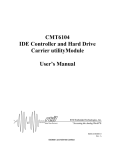
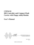
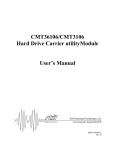
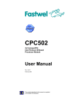
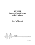
CM102
IDE and Floppy Controller
utilityModule
User’s Manual
BDM-610020012
Rev. A
ISO9001 and AS9100 Certified
CM102
IDE and Floppy utilityModule
User’s Manual
RTD Embedded Technologies, INC.
103 Innovation Blvd.
State College, PA 16803-0906
Phone: +1-814-234-8087
FAX: +1-814-234-5218
E-mail
[email protected]
[email protected]
web site
http://www.rtd.com
CM102
2
RTD Embedded Technologies, Inc
CM102
3
RTD Embedded Technologies, Inc
1.0
1.1.
1.2.
1.3.
1.4.
1.5.
1.6.
1.7.
1.8.
1.9.
Rev. A
Revision History
New
Upgraded to allow stand-alone capability
Upgraded according to new LAS0 mapping - Firmware ver4.
Extended with Appendix. C.
Modified LAS1+8 register – Firmware ver.5.
Power connector description
Watchdog timer description extension
New chapter: 5.4. Reset signals
Minor Corrections
Power connector, JP4 jumper extensions
New manual naming method
Published by:
RTD Embedded Technologies, Inc.
103 Innovation Blvd.
State College, PA 16803-0906
Copyright 1999, 2002, 2003 by RTD Embedded Technologies, Inc.
All rights reserved
Printed in U.S.A.
The RTD Logo is a registered trademark of RTD Embedded Technologies. cpuModule and utilityModule are
trademarks of RTD Embedded Technologies. PhoenixPICO and PheonixPICO BIOS are trademarks of Phoenix
Technologies Ltd. PS/2, PC/XT, PC/AT and IBM are trademarks of International Business Machines Inc. MSDOS, Windows, Windows 95, Windows 98 and Windows NT are trademarks of Microsoft Corp. PC/104 is a
registered trademark of PC/104 Consortium. All other trademarks appearing in this document are the property of
their respective owners.
CM102
4
RTD Embedded Technologies, Inc
CM102
5
RTD Embedded Technologies, Inc
Table of Contents
CHAPTER 1
INTRODUCTION .................................................................................................................1
CM102 IDE AND FLOPPY CONTROLLER UTILITYMODULE .......................................................................................1
FEATURES .................................................................................................................................................................2
CONNECTORS ...........................................................................................................................................................3
GENERAL SPECIFICATIONS ........................................................................................................................................4
CHAPTER 2
CONFIGURING THE UTILITYMODULE .......................................................................5
JUMPERS JP1 JP2 JP3...............................................................................................................................................6
INSTALLING THE UTILITYMODULE ............................................................................................................................6
RECOMMENDED PROCEDURE ...................................................................................................................................7
CHAPTER 3
CONNECTING THE UTILITYMODULE .........................................................................9
CONNECTING THE UTILITY CABLES .........................................................................................................................10
FINDING PIN 1 OF CONNECTORS .............................................................................................................................10
PC/104 BUS CONNECTORS, CN1 AND CN2 ...........................................................................................................12
IDE DRIVE, CN4....................................................................................................................................................14
FLOPPY DRIVE, CN5...............................................................................................................................................15
AUXILIARY POWER, CN6, CN7, TB1, AND TB2 ....................................................................................................16
DRIVE POWER, CN6 ...............................................................................................................................................16
AUXILIARY POWER CONNECTOR CN7 ....................................................................................................................17
POWER I/O, TB1 AND TB2.....................................................................................................................................18
CPUMODULE UTILITY CONNECTOR, CN8 ...............................................................................................................19
KEYBOARD CONNECTOR, CN9 ...............................................................................................................................20
CHAPTER 4
USING THE UTILITYMODULE......................................................................................22
IDE DRIVE .............................................................................................................................................................22
FLOPPY DRIVE ........................................................................................................................................................22
POWER PROTECTION CIRCUITRY ............................................................................................................................23
SPEAKER AND BATTERY .........................................................................................................................................23
CHAPTER 5
RETURN POLICY AND WARRENTY............................................................................25
RETURN POLICY .....................................................................................................................................................25
CHAPTER 6
CM102
LIMITED WARRANTY.....................................................................................................27
6
RTD Embedded Technologies, Inc
CM102
7
RTD Embedded Technologies, Inc
User's Manual
Chapter 1
Introduction
This manual gives information on the CM102 IDE Hard Drive and Floppy Controller utilityModule. This module
allows you to connect standard IDE hard drives, CD-ROM's and floppy drives to your PC/104 system and provides
connectors for Keyboard and reset lines from your cpuModule for system configuration. This manual was written
primarily for use of the CM102 with the RTD family of IDAN systems. A power connector is available to connect to
the hard drive and floppy drive along with a power I/O terminal block for powering your external system devices. A
battery is included for the cpuModule backup of the Real Time Clock. There is a speaker installed for use with the
cpuModule.
CM102 IDE and Floppy Controller utilityModule
The CM102 utilityModule was designed to provide an IDE hard drive and floppy controller in the PC/104 stack to
support the Real Time Devices family of cpuModules and IDAN systems.
CM102
1
RTD Embedded Technologies, Inc.
Features
The following are major features of the CM102 utilityModule.
IDE Controller and Drive
• Enable/Disable mode -- Allows disabling the controller when not connected
to IDE drives.
• Jumper selection of primary or secondary IDE interface in bus mode
• Primary -- IDE Interface at 1F0-1F7h, 3F6-3F7h, Interrupt 14
• Secondary -- IDE Interface at 170-177h, 376-377h, Interrupt 15
Floppy Controller
• Supports two 360 KB, 1.2MB, 720KB or 1.44MB drives
• Enable/Disable mode -- Allows disabling the controller when not connected
to floppy drives.
• Solder Blob "B1" to configure the Floppy interface as primary or secondary
mode.
Real Time Clock Battery
• The battery, BAT1, is a solder-in long life backup that is typically 3.0 to 3.6
V. Real Time Clocks on cpuModules take an input voltage of 2.40 to 4.15
V.
• This battery is used by the cpuModule when the system power is removed,
to preserve the date and time of the Real Time Clock.
• There is a protection circuit to prevent applying a charge to the battery and
limit the output current.
Speaker
• A speaker is soldered on the utilityModule and connected to pins 1 and 2 of
Multifunction connector CN8.
CM102
2
RTD Embedded Technologies, Inc
Connectors
Connectors provided are:
• CN1: PC/104 Bus (XT)
• CN2: PC/104 Bus (AT)
• CN3: Reserved
• CN4: IDE cable connector
• CN5: Floppy cable connector
• CN6: Drive power interface connector
• CN7: Auxiliary Power connector
• CN8: cpuModule utility connector
• CN9: Keyboard / Reset connector
• CN10: IDE drive activity external LED connector
• TB1: +5, +12 Vdc, and ground I/O terminal block
• TB2: -12 Vdc and two grounds I/O terminal block
CM102 IDE and Floppy controller utilityModule
3
Real Time Devices USA, Inc.
General Specifications
•
•
•
•
•
•
•
•
CM102
Dimensions: 3.575 x 3.775 x 0.6" (90.2 x 95.9 x 15 mm)
Weight (mass): 3.0 ounces (85 grams)
6-layer PCB
Operating conditions: (not including drive)
temperature: -40 - +85 degrees C
relative humidity: 0 - 95%, non-condensing
Storage temperature: -55 to +85 degrees C
Power Requirements: 125 mA @ 5 Vdc (typical)
4
RTD Embedded Technologies, Inc
Chapter 2
Configuring the utilityModule
The following sections contain information on configuring the utilityModule.
CM102 IDE and Floppy controller utilityModule
5
Real Time Devices USA, Inc.
Jumpers JP1 JP2 JP3
The utilityModule is configured by positioning jumpers. Jumpers are labeled on the board as "JP"
followed by a number.
The Jumpers on the CM102 are three-pin jumpers allowing two settings:
•
•
Pins 1 and 2 connected
Pins 2 and 3 connected
1
2
3
The figure below shows jumper locations.
JP1 - IDE Enable
JP2 - IDE Mode
JP3 - Floppy
Drive Enable
Jumper
JP1
Position 1-2
IDE
ENABLE
Position 2-3
IDE
DISABLE
JP2
IDE MODE
PRIMARY
IDE MODE
SECONDARY
JP3
FLOPPY
ENABLE
FLOPPY
DISABLE
Use
3
pin
jumper
Use to Enable and Disable the IDE controller
Factory Default: pins 1 - 2 (closed) IDE Enabled
3
pin
jumper
Used to set the IDE controller to Primary or Secondary
Factory Default: pins 1 - 2 (closed) IDE Primary
3
pin
jumper
Use to Enable and Disable the Floppy controller
Factory Default: pins 1 - 2 (closed) Floppy Enabled
Installing the utilityModule
Since the utilityModule uses a PC/104 stackthrough bus, the only hardware installation you will do is placing the
module to the PC/104 stack. To do this, you will connect the PC/104 bus connector with the matching connector of a
RTD cpuModule.
CM102
6
RTD Embedded Technologies, Inc
Recommended Procedure
We recommend you follow the procedure below to ensure that stacking of the modules does not damage connectors
or electronics.
• Turn off power to the PC/104 system or stack.
• Select and install standoffs to properly position the utilityModule on the PC/104 stack.
• Touch a grounded metal part of the stack to discharge any buildup of static electricity.
• Remove the utilityModule from its anti-static bag.
• Check that keying pins in the PC/104 bus connector are properly positioned.
• Check the stacking order: make sure an XT bus card will not be placed between two AT bus
cards, or it will interrupt the AT bus signals.
• Hold the utilityModule by its edges and orient it so the bus connector pins line up with the
matching connector on the stack.
• Gently and evenly press the utilityModule onto the PC/104 stack.
CAUTION:
Do not force the module onto the stack! Wiggling the module or applying too much
force may damage it. If the module does not readily press into place, remove it,
check for bent pins or out-of-place keying pins, and try again.
CM102 IDE and Floppy controller utilityModule
7
Real Time Devices USA, Inc.
CM102
8
RTD Embedded Technologies, Inc
Chapter 3
Connecting the utilityModule
The following chapter is written based on the premise that you are using the cm102 utilityModule in
conjunction with a RTD cpuModule and all pin descriptions are based upon RTD's standard for cpuModule pinouts.
To use these interfaces, you must connect to the 10 pin Multifunction connector of the
cpuModule to the 10 pin cpuModule utility connector of the CM102 making sure the orientation
of pin 1 is correct. A 10-pin ribbon cable will correctly align all of the signals to the same pins
on the corresponding board.
CN8 cpuModule
utility connector
connected to a rtd
cpuModule
Multifunction
connector with a
10-pin ribbon cable
in an IDAN
configuration
CN9 Keyboard connector with
wiring harness connected to reset
switch and keyboard connector.
CM102 IDE and Floppy controller utilityModule
9
Real Time Devices USA, Inc.
Connecting the utility cables
The following sections describe connectors of the utilityModule.
The figure below shows connector locations.
CN10 - IDE Drive
Activity
LED
Connector
CN6
Drive
Power Connector
CN5 - Floppy Drive
Connector
CN4 - IDE Drive
Connector
CN9 - Keyboard and
Reset Connector
TB2 - Power I/O
Terminal Block
CN8 - cpuModule
Utility Connector
TB1 - Power I/O
Terminal Block
CN3 - Reserved
CN1 - XT Bus
CN2 - AT Bus
CN7 - Power
Connector Descriptions
Connectors
Connector
CN1
CN2
CN3
CN4
CN5
CN6
CN7
CN8
CN9
CN10
TB1 & TB2
Function
PC/104 XT Bus
PC/104 AT Bus
Factory use only
IDE
Floppy
IDE / Floppy Power Out
utilityModule Power
cpuModule Utility
Keyboard / Reset
IDE Drive Activity LED
+5, +12, -12 Vdc Power I/O
Size
64 pin
40 pin
40 pins
34 pins
4 pins
16 pins
10 pins
8 pins
2 solder holes
6 terminals
Finding Pin 1 of Connectors
CM102
10
RTD Embedded Technologies, Inc
The pin 1 end of connectors is indicated by a white area silk-screened on the PC board. It is also indicated by a
square solder pad visible on the bottom of the PC board.
Please make certain you have correctly identified pin 1 of a connector before you connect to it and attempt to use the
utilityModule.
PIN ASSIGNMENT
2 4 6 8
1 3 5 7
CM102 IDE and Floppy controller utilityModule
11
Real Time Devices USA, Inc.
PC/104 Bus Connectors, CN1 and CN2
Connectors CN1 and CN2 provide PC/104 bus connections. CN1 carries XT bus signals, and CN2 carries additional
signals for the AT bus. The signals on CN1 and CN2 conform to the IEEE P966 standard for the PC/104 bus.
The following tables list the connector pinouts:
PC/104 XT Bus Connector, CN1
Pin
Row A
Row B
1
2
3
4
5
6
7
8
9
10
11
12
13
14
15
16
17
18
19
20
21
22
23
24
25
26
27
28
29
30
31
32
IOCHCHK*
SD7
SD6
SD5
SD4
SD3
SD2
SD1
SD0
IOCHRDY
AEN
SA19
SA18
SA17
SA16
SA15
SA14
SA13
SA12
SA11
SA10
SA9
SA8
SA7
SA6
SA5
SA4
SA3
SA2
SA1
SA0
0V
0V
RESETDRV
+5V
IRQ9
-5V
DRQ2
-12V
ENDXFR*
+12V
(KEYING PIN)
SMEMW*
SMEMR*
IOW*
IOR*
DACK3
DRQ3
DACK1*
DRQ1
REFRESH
SYSCLK
IRQ7
IRQ6
IRQ5
IRQ4
IRQ3
DACK2*
TC
BALE
+5V
OSC
0V
0V
Note: Signals marked with (*) are active low
CM102
12
RTD Embedded Technologies, Inc
PC/104 AT Bus Connector, CN2
Note:
Pin
Row C
Row D
0
1
2
3
4
5
6
7
8
9
10
11
12
13
14
15
16
17
18
19
0V
SBHE*
LA23
LA22
LA21
LA20
LA19
LA18
LA17
MEMR*
MEMW*
SD8
SD9
SD10
SD11
SD12
SD13
SD14
SD15
(KEYING PIN)
0V
MEMCS16*
IOCS16*
IRQ10
IRQ11
IRQ12
IRQ15
IRQ14
DACK0*
DRQ0
DACK5*
DRQ5
DACK6*
DRQ6
DACK7*
DRQ7
+5V
MASTER*
0V
0V
Two locations on the bus have mechanical keying pins to help prevent
misconnection of the PC/104 bus. These keying pins are a part of the PC/104
standard, and we strongly recommend you leave them in place.
If you have other modules without keying pins, we suggest you modify them to
include keying.
Signals marked with (*) are active low.
CM102 IDE and Floppy controller utilityModule
13
Real Time Devices USA, Inc.
IDE Drive, CN4
CN4 is a 40-pin DIL connector used for connecting the IDE drive. The pinout of this connector is shown below.
IDE Drive Connector, CN4
Pin
Signal
Function
in/out
1
2
3
4
5
6
7
8
9
10
11
12
13
14
15
16
17
18
19
20
21
22
23
24
25
26
27
28
29
30
31
32
33
34
35
36
37
38
39
40
RESET*
GND
HD7
HD8
HD6
HD9
HD5
HD10
HD4
HD11
HD3
HD12
HD2
HD13
HD1
HD14
HD0
HD15
GND
N/C
AEN
GND
IOW*
GND
IOR*
GND
IOCHRDY
BALE
N/C
GND
IRQ
IOCS16*
A1
GND
A0
A2
HCS0*
HCS1*
LED
GND
Reset HD
Ground signal
HD data 7
HD data 8
HD data 6
HD data 9
HD data 5
HD data 10
HD data 4
HD data 11
HD data 3
HD data 12
HD data 2
HD data 13
HD data 1
HD data 14
HD data 0
HD data 15
Ground signal
Not Connected
Address Enable
Ground signal
I/O Write
Ground signal
I/O Read
Ground signal
I/O Channel Ready
Bus Address Latch Enable
Not Connected
Ground signal
Interrupt Request
16 bit transfer
Address 1
Ground signal
Address 0
Address 2
HD Select 0
HD Select 1
HDD activity LED (-)
Ground signal
out
-in/out
in/out
in/out
in/out
in/out
in/out
in/out
in/out
in/out
in/out
in/out
in/out
in/out
in/out
in/out
in/out
--out
-out
-out
-in
out
-in
in
out
-out
out
out
out
in
--
Note: Signals marked with (*) are active low
CM102
14
RTD Embedded Technologies, Inc
Floppy Drive, CN5
CN5 is a 34-pin DIL connector that provides the standard signals to connect one or two floppy disk drives. The
pinout of this connector is shown below.
Floppy Drive Connector, CN5
Pin
Signal
Function
In/out
2
4
6
8
10
12
14
16
18
20
22
24
26
28
30
32
34
ODD
PINS
RWC*
N/C
N/C
INDEX*
MOTEN1*
DRVSEL1*
DRVSEL2*
MOTEN2*
DIRECTION*
STEP*
WRDATA*
WREN*
TRACK0*
WRPROT*
RDDATA*
HEADSEL*
DSKCHG*
GND
write precompensation
Not Connected
Not Connected
index pulse
motor 1 enable
drive select 1
drive select 1
motor 2 enable
step direction
step pulse
write data
write enable
track 0 signal
write protect
read data
head select
disk change
Ground signal
out
--in
out
out
out
out
out
out
out
out
in
in
in
out
in
--
Note: Signals marked with (*) are active low
CM102 IDE and Floppy controller utilityModule
15
Real Time Devices USA, Inc.
Auxiliary Power, CN6, CN7, TB1, and TB2
WARNING! If you improperly connect power, the module will almost certainly be
destroyed. Please verify power connections to the module before
applying power.
The power supply can be conveyed to the utilityModule either through the PC/104 bus (CN1 and
CN2) or through the Auxiliary Power connectors, CN7, TB1, AND TB2. The utilityModule only
uses +5 VDC and ground. +12 VDC, -12 VDC and -5 VDC may be required on other PC/104
boards in the system.
Drive Power, CN6
CN6 is used to power an external Hard drive, CD-ROM, and Floppy drive. The pinout is
the same as a standard power connector used on PC-Computer Power Supplies for ease of
use with a standard power cable.
Drive Power Connector CN6
Pin
1
2
3
4
Signal
+12 V
GND
GND
+5 V
Function
+12 Volts DC
Ground
Ground
+5 Volts DC
Looking down at the connector, the pinout of the Drive Power connector CN6 is:
1
+ 12 V
CM102
2
GND
3
GND
16
4
+5V
RTD Embedded Technologies, Inc
Auxiliary Power Connector CN7
The auxiliary power connector is used to supply 3.3 volts for the PCI bus of the cpuModule if a stackthrough
connector is installed
Pin
1
2
3
4
5
6
7
8
9
10
11
12
Signal
GND
+5 V
N/C
+12 V
-5 V
-12 V
GND
+5 V
GND
+3.3 V
CPU V+
+3.3 V
Function
Ground
+5 Volts DC
RESERVED
+12 Volts DC
-5 Volts DC
-12 Volts DC
Ground
+5 Volts DC
Ground
See Note
See Note
See Note
Facing the connector pins, the pinout of the Auxiliary Power connector is:
11
CPU V+
3.3 V
12
9
GND
3.3 V
10
7
GND
+5 V
8
5
-5 V
-12 V
6
3
N/C
+12 V
4
1
GND
+5 V
2
NOTES!
-5 VDC, +12 VDC and -12 VDC voltages are not used by the module,
but are connected to the PC/104 bus connectors, CN1 and
CN2.
The 3.3 V pins are used to supply the PCI bus if the stackthrough
connector to the cpuModule is installed.
The CPU V+ is based upon the voltage the cpu uses which can vary
between cpuModules.
Don’t use this as a source of 3.3 volts and don’t connect this pin to a
3.3 volt power supply.
CM102 IDE and Floppy controller utilityModule
17
Real Time Devices USA, Inc.
Power I/O, TB1 and TB2
TB1 and TB2 are power I/O connectors and are primarily for use in IDAN systems. The
terminals are marked clearly with the appropriate signal for ease of external power I/O
connections. -12 Vdc and +12 Vdc are not used on the utilityModule but connect directly
to the bus to supply other modules in the stack. Use a flat blade screwdriver to tighten
the screw against the inserted wire.
Terminal block Connector TB1
Pin
TB1-1
TB1-2
TB1-3
TB2-1
TB2-2
TB2-3
CM102
Signal
+12 V
GND
+5 V
GND
-12 V
GND
Function
+12 Volts DC
Ground
+5 Volts DC
Ground
-12 Volts DC
Ground
18
RTD Embedded Technologies, Inc
cpuModule Utility Connector, CN8
The cpuModule Utility Connector CN8 is a feed-through connector to the following interfaces of
a RTD cpuModule:
• AT keyboard
• Speaker input
• System reset output
• Battery output
The following table gives the pinout of the CN8 and its connections to CN9.
CN8
Pin
1
2
3
4
5
6
7
8
9
10
Signal
Function
SPKR+
SPKRRESET
N/C
KBD
KBC
CPU GND
KBP
BAT
N/C
Speaker input
Speaker input (+5 volts)
Manual push button reset
RESERVED
Keyboard Data
Keyboard Clock
Battery Neg (cpu Gnd)
Keyboard Power (+5 volts)
Battery Pos
RESERVED
CN9
Pin
N/C
N/C
7
N/C
3
4
2&8
1
N/A
N/A
Facing the connector pins, the pinout is:
9
BAT
N/C
10
7
CPU GND
KBP
8
CM102 IDE and Floppy controller utilityModule
5
KBD
KBC
6
19
3
RESET
N/C
4
1
SPKR+
SPKR2
Real Time Devices USA, Inc.
Keyboard connector, CN9
The keyboard connector CN9 is a feed through-connector to the following interfaces of a
cpuModule:
• AT keyboard
• System reset input
The following table gives the pinout of the keyboard connector.
Pin
1
2
3
4
5
6
7
8
Signal
KBP
CPU GND
KBD
KBC
N/C
N/C
RESET
CPU GND
Function
Keyboard Power (+5 volts)
cpuModule Ground
Keyboard Data
Keyboard Clock
RESERVED
RESERVED
Manual push button reset
cpuModule Ground
Facing the connector pins, the pinout is:
CM102
7
RESET
CPU GND
5
N/C
N/C
3
KBD
KBC
8
6
4
20
1
KBP
CPU
GND
2
RTD Embedded Technologies, Inc
CM102 IDE and Floppy controller utilityModule
21
Real Time Devices USA, Inc.
Chapter 4
Using the utilitymodule
IDE Drive
The CM102 provides an IDE interface standard IDE Drive. This drive can be set up as the primary or the secondary
drive (you must be sure that your CPU BIOS supports both primary and secondary drives).
Since the CM102 provides the IDE decoding on-board you must be sure to disable any other IDE controllers that
might be present in your system or set one of the controllers to Secondary to prevent controller chip interface
conflicts.
You may need to run the bios setup program for your cpuModule or computer to configure the correct hard drive
type.
Floppy Drive
The CM102 provides a Floppy Drive interface. This drive can be set up as the primary or the secondary (you must be
sure that your CPU BIOS supports both primary and secondary drives).
Since the CM102 provides the Floppy decoding on-board you must be sure to disable any other Floppy controllers
that might be in your system or set one of the controllers to Secondary to prevent controller chip interface conflicts.
Solder blob "B1" is factory default set as primary and should only be changed if two floppy drive controllers are
being used.
You may need to run the bios setup program for your cpuModule or computer to configure the correct Floppy drive
type.
CM102
22
RTD Embedded Technologies, Inc
Power Protection Circuitry
To reduce the risk of damage due to power-supply problems, the utilityModule includes several protective
components.
Module Power-Supply Protection
The utilityModule includes components to help prevent damage due to problems with the +5 VDC power supply
from the PC/104 bus or power-supply connector. Protection is provided for:
• Over-current
• Reversed polarity
• Excessive voltage
This protection is only for the utilityModule, and will not protect other devices in a PC/104 stack .
The protective fuse is replaceable and is available from electronics suppliers. Its description and part number are:
Littelfuse Nano2 SMF 1.0 amp, R451-001
Caution:
Replace fuses only with parts of identical current and
voltage rating.
Speaker and Battery
The utilityModule provides a small speaker for cpuModule sound output. The speaker has 8 ohms of impedance and
can be driven from the standard 0.1 watts of power supplied by the cpuModule.
A lithium battery provides approximately 3 Vdc of backup power to the Real Time Clock on the cpuModule. It has
a diode to prevent a charge from being applied to the battery and resistor to limit the output current. To disable the
protection circuit, install a solder blob on "B2" on the bottom side of the board next to CN8.
CM102 IDE and Floppy controller utilityModule
23
Real Time Devices USA, Inc.
CM102
24
RTD Embedded Technologies, Inc
Chapter 5
RETURN POLICY and WARRENTY
Return Policy
If the utilityModule requires repair, you may return it to us by following the procedure listed below:
Caution:
Failure to follow this return procedure will almost always
delay repair! Please help us expedite your repair by
following this procedure.
1) Read the limited warranty which follows.
2) Contact the factory and request a Returned Merchandise Authorization (RMA) number.
3) On a sheet of paper, write the name, phone number, and fax number of a technically-competent person who can
answer questions about the problem.
4) On the paper, write a detailed description of the problem with the product. Answer the following questions:
• Did the product ever work in your application?
• What other devices were connected to the product?
• How was power supplied to the product?
• What features did and did not work?
• What was being done when the product failed?
• What were environmental conditions when the product failed?
5) Indicate the method we should use to ship the product back to you.
• We will return warranty repairs by UPS Ground at our expense.
• Warranty repairs may be returned by a faster service at your expense.
• Non-warranty repairs will be returned by UPS Ground or the method you select, and will
be billed to you.
6) Clearly specify the address to which we should return the product when repaired.
7) Enclose the paper with the product being returned.
8) Carefully package the product to be returned using anti-static packaging! We will not be responsible for products
damaged in transit for repair.
7) Write the RMA number on the outside of the package.
8) Ship the package to:
RTD Embedded Technologies, Inc.
103 Innovation Blvd.
State College, PA 16803
USA
CM102 IDE and Floppy controller utilityModule
25
Real Time Devices USA, Inc.
CM102
26
RTD Embedded Technologies, Inc
Chapter 6
Limited Warranty
RTD Embedded Technologies, Inc. warrants the hardware and software products it manufactures and produces to
be free from defects in materials and workmanship for one year following the date of shipment from RTD
Embedded Technologies, INC. This warranty is limited to the original purchaser of product and is not transferable.
During the one year warranty period, RTD Embedded Technologies will repair or replace, at its option, any
defective products or parts at no additional charge, provided that the product is returned, shipping prepaid, to RTD
Embedded Technologies. All replaced parts and products become the property of RTD Embedded Technologies.
Before returning any product for repair, customers are required to contact the factory for an RMA number.
THIS LIMITED WARRANTY DOES NOT EXTEND TO ANY PRODUCTS WHICH HAVE BEEN DAMAGED
AS A RESULT OF ACCIDENT, MISUSE, ABUSE (such as: use of incorrect input voltages, improper or
insufficient ventilation, failure to follow the operating instructions that are provided by RTD Embedded
Technologies, "acts of God" or other contingencies beyond the control of RTD Embedded Technologies), OR AS A
RESULT OF SERVICE OR MODIFICATION BY ANYONE OTHER THAN RTD Embedded Technologies.
EXCEPT AS EXPRESSLY SET FORTH ABOVE, NO OTHER WARRANTIES ARE EXPRESSED OR
IMPLIED, INCLUDING, BUT NOT LIMITED TO, ANY IMPLIED WARRANTIES OF MERCHANTABILITY
AND FITNESS FOR A PARTICULAR PURPOSE, AND RTD Embedded Technologies EXPRESSLY DISCLAIMS ALL WARRANTIES NOT STATED HEREIN. ALL IMPLIED WARRANTIES, INCLUDING
IMPLIED WARRANTIES FOR MECHANTABILITY AND FITNESS FOR A PARTICULAR PURPOSE, ARE
LIMITED TO THE DURATION OF THIS WARRANTY. IN THE EVENT THE PRODUCT IS NOT FREE
FROM DEFECTS AS WARRANTED ABOVE, THE PURCHASER'S SOLE REMEDY SHALL BE REPAIR OR
REPLACEMENT AS PROVIDED ABOVE. UNDER NO CIRCUMSTANCES WILL RTD Embedded
Technologies BE LIABLE TO THE PURCHASER OR ANY USER FOR ANY DAMAGES, INCLUDING ANY
INCIDENTAL OR CONSEQUENTIAL DAMAGES, EXPENSES, LOST PROFITS, LOST SAVINGS, OR
OTHER DAMAGES ARISING OUT OF THE USE OR INABILITY TO USE THE PRODUCT.
SOME STATES DO NOT ALLOW THE EXCLUSION OR LIMITATION OF INCIDENTAL OR
CONSEQUENTIAL DAMAGES FOR CONSUMER PRODUCTS, AND SOME STATES DO NOT ALLOW
LIMITATIONS ON HOW LONG AN IMPLIED WARRANTY LASTS, SO THE ABOVE LIMITATIONS OR
EXCLUSIONS MAY NOT APPLY TO YOU.
THIS WARRANTY GIVES YOU SPECIFIC LEGAL RIGHTS, AND YOU MAY ALSO HAVE OTHER
RIGHTS WHICH VARY FROM STATE TO STATE.
CM102 IDE and Floppy controller utilityModule
27
Real Time Devices USA, Inc.
RTD Embedded Technologies, Inc.
103 Innovation Blvd.
State College PA 16803-0906
USA
Our website: www.rtd.com
CM102
28
RTD Embedded Technologies, Inc