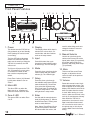
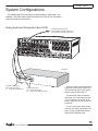
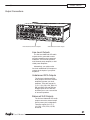
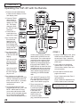
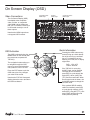
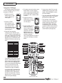
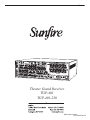
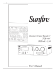
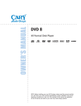
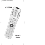
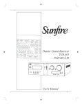
1
Theater Grand Processor
TGP-401
TGP-401-230
SAFETY
Important Safety Instructions
1. Read Instructions
2. Keep these Instructions
3. Heed all Warnings.
4. Follow all Instructions
5. Do not use this apparatus near
water.
6. Clean only with a dry cloth.
7. Do not install near any heat sources such as radiators, heat registers,
stoves, or other apparatus (including
amplifiers) that produce heat.
8. Unplug this apparatus during lightning storms or when unused for long
periods of time.
9. Refer all servicing to qualified service personnel. Servicing is required
when the apparatus has been damaged in any way, such as a powersupply cord or plug is damaged, liquid
has been spilled or objects have fallen
into the apparatus, the apparatus has
been exposed to rain or moisture,
does not operate normally, or has
been dropped.
2
10. Ventilation — The apparatus
should be situated so that its location
or position does not interfere with its
proper ventilation. For example, the
apparatus should not be situated on a
bed, sofa, rug, or similar surface that
may block any ventilation openings; or
placed in a built-in installation such as
a bookcase, cabinet, or closed equipment rack that may impede the flow of
air through ventilation openings.
11. Power Sources — The apparatus
should be connected to a power supply only of the type described in these
operation instructions or as marked on
the apparatus.
12. Power Cord Protection — Power-supply cords should be routed so
that they are not likely to be walked
upon or pinched by items placed upon
or against them, paying particular attention to cords at plugs, convenience
receptacles, and the point where they
exit the apparatus.
13. Non-use Periods—The power
cord of the apparatus should be unplugged from the outlet when unused
for a long period of time.
14. Object and Liquid Entry — Care
should be taken so that objects do not
fall into and liquids are not spilled into
the inside of the apparatus.
15. Servicing — The user should
not attempt to service the apparatus
beyond those means described in this
operating manual. All other servicing
should be referred to qualified service
personnel.
User's Manual
SAFETY
16. To prevent electric shock, do not
use this polarized plug with an extension cord, receptacle or other outlet
unless the blades can be fully inserted
to prevent blade exposure.
Pour préevenir les chocs électriques
ne pas utiliser cette fiche polariseé
avec un prolongateur, un prise de
courant ou une autre sortie de courant, sauf si les lames peuvent être
insérées à fond sans laisser aucune
parIVe à découvert.
17. Grounding or Polarization —
Precautions should be taken so that
the grounding or polarization means
of the Component is not defeated.
This apparatus does not exceed the
Class A/Class B (whichever is applicable) limits for radio noise emissions
from digital apparatus as set out in the
radio interference regulations of the Canadian Department of Communications.
ATTENTION — Le présent appareil numérique n'émet pas de bruits
radioélectriques dépassant las limites
applicables aux appareils numériques
de class A/de class B (selon le cas)
prescrites dans le règlement sur le
brouillage radioélectrique édicté par
les ministere des communications du
Canada.
WARNING – TO REDUCE THE RISK OF FIRE OR ELECTRIC SHOCK,
DO NOT EXPOSE THIS APPLIANCE TO RAIN OR MOISTURE.
CAUTION: TO PREVENT ELECTRIC SHOCK, MATCH WIDE BLADE
OF PLUG TO WIDE SLOT, FULLY INSERT.
ATTENTION: POUR ÉVITER LES CHOCS ÉLECTRIQUES, INTRODUIRE LA LAME LA PLUS LARGE DE LA FICHE DANS LA BORNE
CORRESPONDANTE DE LA PRISE ET POUSSER JUSQU’AU FOND.
EXAMPLE OF ANTENNA GROUNDING ACCORDING TO NATIONAL
ELECTRICAL CODE INSTRUCTIONS CONTAINED IN ARTICLE
810–“RADIO AND TELEVISION EQUIPMENT”
GROUND CLAMP
ANTENNA
LEAD IN WIRE
GROUND CLAMPS
SERVICE
ENTRANCE
EQUIPMENT
ANTENNA DISCHARGE UNIT
(NEC SECTION 810-20)
GROUNDING
CONDUCTORS
(NEC SECTION 810-21)
GROUND CLAMPS
POWER SERVICE GROUNDING
ELECTRODE SYSTEM
(NEC ART 250, PART H)
NEC NATIONAL ELECTRICAL CODE.
NOTE TO CATV INSTALLER
This reminder is to call the CATV system installer's attention to Article 820-40 of the NEC that provides guidelines for proper grounding and in particular, specifies that the cable ground shall be connected to the grounding
system of the building as close to the point of cable entry as practical.
OUTSIDE ANTENNA GROUNDING
If an outside antenna is connected to the receiver, be sure the antenna system is grounded so as to provide
some protection against voltage surges and built-up static charges. Article 810 of the National Electrical Code,
ANSI/NFPA 70, provides information with regard to proper grounding of the lead-in wire to an antenna-discharge
unit, connection to grounding electrodes, and requirements for the grounding electrode. See Figure above.
User's Manual
3
CHAPTER 1
Contents
Important Safety Instructions .....................2
Chapter 1: Introduction ...............................5
Overview.....................................................7
Quick Start Guide .......................................8
Front Panel Features ................................10
Rear Panel Features ................................12
Installation ................................................14
Chapter 2: System Configurations ...........15
Chapter 3: Remote Control ......................25
Chapter 4: On Screen Display (OSD) .......31
Chapter 5: Using the TGP-401 ..................37
Input settings ............................................37
Bass Management....................................38
Video Conversion .....................................38
Manual Setup ...........................................39
Automatic Setup Procedure......................40
Automatic and Manual Equalization .........41
Surround Modes .......................................42
Sonic Holography .....................................45
FM and AM Tuner Operation ....................46
Recording .................................................47
Zone 2 Operation......................................48
Triggers.....................................................49
Appendix .....................................................50
Speaker Placement ..................................50
The RS-232 Port.......................................52
Troubleshooting Guide .............................53
Remote Control Codes .............................56
Specifications ...........................................59
Default Input Table....................................60
Optional VIA!migo iPod Dock ...................61
Optional SIRIUS Satellite Radio Tuner .....63
Optional Olé-2SF Touchpads ...................66
Limited Warranty ......................................67
Service Assistance ...................................67
4
Read the Safety Instructions carefully before connecting and using
your Sunfire Theater Grand Processor TGP-401.
Chapter 1 is a general introduction
to the features, details and installation of your TGP-401.
Chapter 2 shows many options for
connecting your source equipment
to the TGP-401.
Chapter 3 describes the details and
operation of the advanced remote
control.
Chapter 4 shows the various menus
of the On Screen Display, and how
to adjust and customize your TGP401.
Chapter 5 describes the available
modes, options and operational
details of the TGP-401.
The Appendix shows some additional information, including a
troubleshooting guide, optional
components, the warranty and
service assistance details
To find out more about this and other
Sunfire products, please visit our
website: www.sunfire.com
User's Manual
CHAPTER 1
Introduction
Thank you for purchasing a Sunfire
TGP-401 Theater Grand Processor.
We hope that you enjoy it and the
music it makes as much as we have
enjoyed creating it for you.
As with our entire line of products,
the TGP-401 is brimming with exclusive, high-performance technologies
that deliver powerful movie and music
experiences. These include the following features:
Features:
• SIRIUS®-ready
• AM/FM tuners with RDS feedback
• VIA!migo™ support for native
iPod® control via OSD and front
panel
• Two touchpad ports for optional
Olé-2SF Film Interactive touchpads. Feedback for functions and
metadata from SIRIUS and iPod
• Automatic setup and room correction w/ included microphone
• Input volume matching
• A/V sync to match audio to video
Connections:
•
•
•
•
•
•
4 Analog inputs, 2 outputs
4 Video inputs, 2 outputs
4 optical digital inputs, 1 output
4 coaxial digital inputs, 1 output
7.1 multi-channel input
7.1 unbalanced RCA preamp
outputs
• 7.1 balanced XLR preamp outputs
• Balanced and unbalanced Zone
2 preamp outputs
• Assignable, HD-ready front panel
input
User's Manual
Processing:
• Sonic Holography for enhanced
imaging
• Dolby Digital EX and ProLogic IIx
• Dolby Headphone
• DTS-ES, Neo:6, and DTS-96/24
• SourceDirect mode for DSP
bypass
Video:
• Sunfire-designed, 1080p HDMI
v1.3a switching (3 in / 1 out)
• 100 MHz component switching
(3 in / 1 out)
• Video upconversion to component
Integration features
•
•
•
•
Bi-directional RS-232 input
2 IR inputs, 3 outputs
3 Assignable 12V trigger outputs
Maximum and power-on volume
settings for Main and Zone 2
• Power-on source setting for Main
and Zone 2
• PC application for initial setup,
Olé-2SF touchpad programming,
and software upgrades
Miscellaneous:
• Long-grain, solid aluminum front
panel
• Elegant blue LEDs for visual
feedback
• Removable IEC cord
Remote control features
• Fully backlit
• Pre-programmed for most brands
of A/V equipment
• Learns commands from your
other remote controls
• Macro feature lets you program a
sequence of control steps
• Operates up to 19 components
• Does not lose programming
memory when changing batteries
• RF capable with optional MRF260 RF base
Optional accessories
See your Sunfire dealer or visit our
web site for more information regarding the following accessories:
•
•
•
•
SRK-200 Rack mount kit
Olé-2SF touchpads
VIA!migo iPod dock
SC-H1P1 SIRIUS Satellite Radio
antenna/tuner kit
• MRF-260 RF remote control base
External amplifiers
Sunfire Theater Grand Amplifiers
make ideal companions to your
Theater Grand Processor.
See your Sunfire dealer or visit our
web site for more information regarding the following amplifiers:
• TGA-7401 seven channels at 400
watts each
• TGA-7201 seven channels at 200
watts each
5
CHAPTER 1
Unpacking
Your TGP-401 should reach you in
perfect condition. If you do notice any
shipping damage, please contact your
Sunfire Dealer immediately.
Gently lift out the unit and remove
all the packing material and accessories. It is important to save all the
packing materials and the box in
case your TGP-401 ever needs to be
moved or shipped for repair.
Make sure that you keep your sales
receipt. It is the only way to establish
the duration of your Limited Warranty
and it may come in useful for insurance purposes.
Please take a moment to fill out and
mail the Sunfire Customer Response
card. Also read the serial number
located on the rear panel, and record
it here:
Serial #:
___________________________
Purchased at:
___________________________
___________________________
___________________________
___________________________
Date: _______________________
6
User's Manual
CHAPTER 1
Overview
Most features of the TGP-401 can
be operated by the remote control’s
TG401 section.
For the best Home Theater performance, you should calibrate your
speakers and customize the TGP-401
settings for your system. Press the
MENU button on the remote control
to activate the On Screen Display
(OSD). This has several menus which
will allow you to set up your speakers
and calibrate your system correctly.
ON
OFF
PAGE
The remote can also be used to
activate and control all features of the
second zone.
FAV
MAIN
PREV
CH
MUTE
VOL
CH
GUIDE
MENU
INFO
EXIT
SEL
1
2
3
4
5
6
7
8
9
+10
0
ENT
The TGP-401-230 is the export
model, set for 220-240 VAC operation.
Its operation is identical to the TGP401 described in this manual.
Input,
mode, and
setup
Power
on/off
IR window
Use the center three buttons to select either the input, mode, or setup
menus. Then use the input and menu
selection knob to find the item. In the
setup menu, rotate the knob to move
through various menu items and press
the nearby enter button to select an
item.
Zone
Sonic
choice Holography
Select MAIN then any commands that follow
will affect that zone.
Select Zone 2, then any commands that follow within several seconds will affect Zone 2.
It returns to Main Zone control after several
seconds of inactivity.
User's Manual
Input and
menu select
Volume
adjustment
Headphones
Sliding cover
for front inputs and microphone input
Select Sonic Holography
for an enhanced 3D image
of any source.
7
CHAPTER 1
Quick Start Guide
We hope that the following details
will help you get started using your
TGP-401.
1. Take care to read and follow the
safety instructions on pages 2-3.
Also make sure that you read the
notes and details throughout the
manual, especially notes marked
with a warning triangle ( ).
7. Press the remote MAIN button
a few times to make sure you
are on the Main Page 1 Menu in
the remote's display.
8. Set the remote to operate the
TGP-401 by pressing the TG401
button.
2. Add four new AAA batteries to the
remote control.
ON
3. Connect your source equipment
to the TGP-401. Connect the
balanced or unbalanced outputs
of the TGP-401 to the line-level
inputs of your power amplifier, and
connect speakers to the amplifier
Make sure that all of your equipment remains unplugged from the
AC mains until you have made all
the connections.
4. In your DVD player's Audio setup
menu, set the digital output to
BITSTREAM. If this is not set
correctly, the TGP-401 cannot
decode the digital information for
5.1 surround sound playback.
5. The TGP-401's bass management system allows the bass from
each speaker to be redirected to
a subwoofer. Larger speakers can
play the full frequency range, and
smaller speakers such as satellite
types can have their bass redirected. See page 38 for details.
Make a note of which speakers you would like to play the
full frequency range (Large) and
those which will have their bass
redirected. Also make a note of
the approximate distance of each
speaker from your listening position.
6. Turn on the TGP-401, and then
turn on your power amplifier, TV
and source equipment.
8
FAV
MAIN
PREV
CH
MUTE
VOL
EXIT
MENU
Previous
MODE
INFO
12. Stop or pause the source.
Automatic Setup
CH
GUIDE
MENU
11. Play a source, such as a DVD,
and bring up the volume to suit
your taste. Make sure the video
can be seen in the TV monitor.
The TGP-401 now needs to be setup correctly to suit your speakers and
system. This is done using the TGP401 on screen display (OSD) menus.
It can be done either automatically or
manually, as can the EQ adjustment.
This needs to be done when you use
your system for the first time, or if you
change anything such as the speakers or their position.
OFF
PAGE
the knob to select the desired
input.)
EXIT
The TGP-401 comes with a measurement microphone that plugs into
the front panel microphone input.
Next
MODE
SEL
1
2
3
4
5
6
7
8
9
+10
0
ENT
9. The VOL and MUTE buttons will
control the TGP-401 no matter
which source component the
remote is set to operate. The
PUNCH command allows you to
change this if required (see page
28).
10. Turn down the TGP-401 volume
and use the remote or front panel
to select a video source as follows: If you have followed step 8,
the remote now shows the inputs
that can be selected. Select one.
(From the TGP-401 front panel,
you can first press the input button (center, top) and then rotate
Measurement
microphone
(supplied)
The automatic setup procedure
uses the microphone to measure and
evaluate your system. After the measurements are complete, the levels,
crossover frequency, and delay times
of the speakers are automatically
adjusted for the best performance.
Any problems with the speakers
are indicated, for example, it will let
you know if there is low output from a
speaker, or if the polarity is reversed.
Details of the auto-setup are
shown on page 40. Alternatively, you
can use the manual procedure to set
up your system as follows:
User's Manual
CHAPTER 1
Manual Setup
There are three main manual adjustments that can be made using the
SPEAKERS OSD menu:
1. The SPEAKER SIZE menu allows you to enter the crossover
frequency of each speaker. Using
bass management, any bass
below the crossover frequency will
be redirected to your subwoofer.
2. The LEVEL CALIBRATION menu
allows you to adjust the level of
each speaker until they are all
playing at the same level. (The
level calibration test tones are
also a quick way to check that all
your speakers are working.)
3. The SPEAKER DISTANCE menu
allows you to enter the distance
that each speaker is away from
your listening position. The TGP401 then calculates the delay
times.
Details of the manual setup procedure are shown on page 39.
EQ Adjustment
The measurement microphone can
also be used to measure the system
response and adjust the EQ automatically. This will provide a smooth
response and remove room effects.
MAIN MENU
TRIMS
TONE CONTROLS
MODES
PRESETS
SETUP
SETUP
INPUTS
SPEAKERS
VIDEO
MAIN ZONE
ZONE 2
CONTROL
DIGITAL OUT
DIMMER
DN MIX/THRU
LOW/MEDIUM/HIGH
SPEAKERS
AUTO SETUP
SPEAKER SIZE
DISTANCE
LEVEL CALIBRATION
EQ
3. In the MAIN MENU, select
SETUP, and from there select the
SPEAKERS Menu.
Details of the auto-EQ and manual
EQ adjustment are shown on page 41.
4. In the SPEAKERS menu are
the options for AUTO SETUP,
SPEAKER SIZE, DISTANCE,
LEVEL CALIBRATION, and EQ.
The SPEAKERS menu is used to
run the auto-setup, manual setup, and
EQ adjustment.
1. Press the MENU button on the remote to bring up the MAIN MENU
of the OSD on your TV.
Manual adjustments (see page 39)
Manual or Auto EQ adjustment
(see page 41)
NOTE: Quit the OSD at any time
by pressing the nearby EXIT button. Any changes will be saved.
There is no need to navigate back
through previous pages, unless
you want to make more changes.
The TGP-401 front panel display
shows the same messages as the
OSD.
Alternatively, the EQ of pairs of
speakers, or all speakers can be adjusted manually to suit your taste.
OSD Menus
Auto Setup (see page 40)
5. When you have finished the setup
and/or EQ adjustment, press the
remote’s EXIT button to quit the
OSD.
Conclusion
Once the automatic setup or
manual setup is finished, and any EQ
adjustments made, the TGP-401 is
setup correctly and ready for action.
If you play a Dolby Digital or DTS
encoded source, the TGP-401 will automatically select the correct surround
mode. If it is a 2-channel source, you
can select a surround mode using the
remote’s MODE buttons or from the
front panel.
The TGP-401 has many more
options that are described in further
detail in this manual. These options
will help you customize the TGP-401
to suit your tastes. You can do this
after you have used the TGP-401
for a while and have a better idea of
how you would like to customize your
system.
2. Use the navigation pad left, right,
up and down buttons to navigate
through the menus in the next
steps.
User's Manual
9
CHAPTER 1
Front Panel Features
1 2
3
12
4
13
14
5
15
1. Power
This button turns the TGP-401 on
(fully powered up) or into Standby
mode (asleep, but can be turned
on remotely).
16
This display shows which input is
selected, the volume level, surround mode, and other features
such as the setup menus.
To fully turn off power to the TGP401, for example if you are going
on vacation for a week or two,
then use the rear panel power
switch.
6. Mode
Press Zone 2 select (14) followed
by this power button to turn on
Zone 2.
7. Setup
3. Zone 2 LED
This green LED is on when Zone
2 is on.
9
4. Display
5. Input
This blue LED is on when the
Main zone is on. It flashes red
when the remote control is used.
8
Press this button, then cycle
through the inputs with the manual selector (9). The LED will light.
Press this, then cycle through the
various modes with the manual
selector (9). The LED will light.
Press this, then cycle through
the available setup items with the
manual selector (9). Press Enter
(8) to select the required setup
item. Press Input (5) or Mode (6)
to exit the setup menus. The LED
will light when in setup mode.
8. Enter
Use this and the manual selector
knob (9) during setup (7). When a
desired menu item is found, press
enter to select that item.
Note: Setup (7) and Enter (8) can
be used to increase or decrease
dB values within the menus, and
10
10
11
17
The blue LED above the power
switch is on when the TGP-401
main zone is turned on. When the
TGP-401 is turned off, the LED
will turn red.
2. Main LED
6 7
18
used for other things such as to
change the letters of a source
name for example.
9. Manual Selector
Use this to cycle through the
various menu items such as the
inputs (when input (5) is pressed),
the modes (when mode (6) is
pressed), and setup (when setup
(7) is pressed).
10. Mute
This turns off the sound. Press
it again, or adjust the volume
control to return to the previous
volume level.
11. Volume
Rotate this manual control clockwise to increase the volume. The
level will appear in the front panel
display. Note that the control knob
does not rotate when the remote
is used. When turning on a new
source, make sure the level is low,
such as 20, and increase it slowly.
Note: When the TGP-401 is
powered on, the volume is set to
what is was when it was turned
off. It can also be set to come on
at a preset max or min volume
(see the Main Zone in the Setup
menu).
User's Manual
CHAPTER 1
12. IR Receiver Window
This window should be clean
and free from obstruction for the
remote control to work correctly.
13. Main Select
Any changes made after pressing this button will affect the main
zone.
14. Zone 2 Select
Any changes made after pressing
this button will affect Zone 2. If no
changes are made within several
seconds, the unit will revert back
to main select. To turn on Zone 2,
press this button first, followed by
the power button.
15. Sonic Holography
Engage this to add a three dimensional effect, especially to stereo
listening.
16. Digital Input
This will light when a digital audio
source is playing.
17. Front Door
Sliding this door to the left reveals
the front input connections and
the connection point for the supplied measurement microphone.
This is an ideal place for connecting video game consoles or video
cameras.
The front input can be selected by
the remote control or by the input
button (5) and manual selector
(9).
Note: The remote control has a
FRTMD button (front mode) in
the Main Zone and Zone 2. This
works the same as pressing the
front door panel Mode button,
changing the three front RCA
inputs from L/R/composite video,
to component video inputs.
Make sure that the volume
level is turned down when
connecting headphones, or
when playing a new source,
or making any changes. This will
help protect your hearing from
damage.
18. Headphone output
This is where to connect your
headphones. In the MODES
menu of the on screen display,
the headphone output trim can be
adjusted relative to the setting of
the main volume level (11). Also
in the MODES menu and with
the remote, you can select Dolby
Headphone technology on or off.
Dolby Headphone technology
enables you to experience the
surround effects of a five-channel, six-channel, or seven-channel soundtrack through standard
stereo headphones.
Mode
button
and
LED
Component video inputs
or L/R audio and composite video, depending Optical
on the mode button
Input
S-Video
Input
EQ mic
Input
The three RCA inputs can be:
•
Left audio in, right audio in,
and composite video in.
or, if the mode button is
pressed, they can be:
•
Pb, Pr, and Y component video
inputs (the LED will light).
There is also a digital optical
input, and an S-Video input.
Measurement
microphone
The measurement microphone
connects in the right hand corner
during the auto-setup and autoEQ procedures.
User's Manual
11
CHAPTER 1
Rear Panel Features
3
4
5
6
7
10
11
8
2
1
9
1. AM Antenna
These connections are for the
supplied AM loop antenna.
2. FM Antenna
The supplied FM antenna fits this
“F-type” coaxial connector. Other
antennas can be fitted for improved reception.
3. SIRIUS Connection
This connection is provided for
the optional SIRIUS tuner kit
(SC-H1P1). This consists of an
antenna for picking up satellite radio transmissions, and a tuner unit
that connects here. The connection allows left and right audio and
control data to enter the TGP-401.
The OSD menus of the TGP-401
allow you to select your favorite
SIRIUS Satellite radio stations as
presets for easy recall. See page
63 for more details.
4. Audio/Video
These audio, composite-video
and S-video inputs connect to the
outputs of your audio video components. When these inputs are
selected, the audio will be heard
in your system, and the video will
be seen on the TV screen.
12
12
13
14 15
Fixed audio output is available, for
example for stereo recording to
a tape player, independent of the
TGP-401 volume. A stereo audio
Zone 2 output is also available.
S-Video and composite video outputs are available for monitoring,
as well as a composite video output for Zone 2. Note that the video
sources you would like to play
in Zone 2 must use composite
video. (There is no video up/down
conversion in Zone 2.)
5. Component Video
These inputs connect to the
component-video outputs of your
video sources if they have this
capability. When these inputs are
selected, the TGP-401 will automatically route any video signals
going into these jacks to the component video outputs. Note that
component video provides the
best picture compared to composite or S-video.
If your TV monitor has component
video inputs, connect them to the
TGP-401's component outputs.
The TGP-401 can also up-convert
composite video and S-video from
the other inputs.
16
17 18
6. HDMI
Use these to connect any HDMI
components you may have in your
system. Three are inputs, and
one is an output to your HDMIequipped TV. This supports 1080p
and HDMIv1.3a sources. No onscreen-display or audio decoding
inside the TGP-401 is available
from the HDMI inputs. Always
connect a separate digital audio
input cable when using HDMI.
7. Preamp Outputs
These line-level unbalanced RCA
audio outputs connect to external
amplifiers to power your loudspeakers. There are outputs for
L, R, C, LS1, RS1, LS2, RS2, LB,
RB, and SUB. (LS2 and RS2 are
straight copies of LS1 and RS1,
and allow you to run a second set
of surround speakers.
8. Balanced Outputs
These line-level balanced XLR
audio outputs connect to external
amplifiers to power your loudspeakers. There are outputs for L,
R, C, LS, RS, LB, RB, L Z2, R Z2,
and SUB.
User's Manual
CHAPTER 1
9. 8-CH Inputs
10. Digital Connections
There are four S/PDIF digital
coaxial inputs, with one coaxial
output, and four digital optical
inputs with one optical output.
Use these with source equipment
that has digital audio connections.
12. RS-232 Port
This communications port allows
future updates of the software
from Sunfire to be made to your
TGP-401. It may also be used for
control by 3rd party integration
systems.
13. VIA!migo Port
This port allows connection of a
proprietary VIA!migo iPod docking station system available from
Sunfire.
Do not connect this port to
Ethernet or other computer
networks.
14. Infrared (IR)
These inputs and outputs are
used in custom installations
to control the Main Zone and
Zone 2 from a remote location.
The Infrared (IR) Input on the
TGP-401 utilizes Tip as +12V,
Ring as IR, and Sleeve as
Ground. In order to correctly utilize standard two or three wire IR
equipment, the wiring needs to be
connected as shown.
11. TP1 and TP2
Optional Olé-2SF Film Interactive touchpads are available for
external control of Zone 2 or the
Main Zone.
These wall-mounted touchpads
connect to TP1 or TP2 using standard CAT-5 cable.
User's Manual
Standard IR Sensor
IR
Note: if you use HD-DVD or Bluray DVD players that have 7.1
analog audio outputs, use this 8channel input. It is fully processed
in DSP with bass management,
speaker delays and tone controls.
Only the left/right jacks are available in Zone 2.
Do not connect these ports
to Ethernet or other computer networks.
Zone 2 (2)
GND
+12VDC
These analog audio inputs can
connect to the output of an external surround processor, or a
source component such as DVDAudio, SACD, or a DVD player
with its own surround decoder.
You can select this as an input
from the front panel or remote
control. The eight channels of
analog audio will then pass into
the TGP-401.
Please contact your Sunfire
dealer for more information. Use
only touchpads that are recommended by Sunfire.
Use the screw terminal input to
connect standard IR distribution
equipment (such as an IR sensor)
for Main Zone or Zone 2 operation. The screw terminals accepts
bare wire connections (2 or 3-wire
input and 2-wire output).
The remote sensors can be in a
different room, or your main room.
15. Trigger Outputs
These allow the TGP-401 to control the turn-on of other trigger-enabled equipment in your system.
16. IEC Line Cord Socket
The TGP-401 comes with a
detachable linecord that connects
here.
Plug the line cord into an AC wall
socket or power strip that is correctly configured with the voltage
specified for your model.
17. AC Line Fuse
Always unplug the linecord from
the AC Mains before checking
or changing the fuse. If this fuse
blows, you must replace it with a
fuse of exactly the same size and
current rating.
18. Power Switch
If this is switched off, the TGP-401
will be off, and cannot be turned
on even with the front panel
power switch, the remote control,
or optional Olé-2SF touchpads.
In normal operation, leave this
switch on. Turn it off if you will not
be using the TGP-401 for extended periods.
13
CHAPTER 1
Installation
Observe the following precautions
when choosing a location for your
TGP-401:
Connection Tips
Video Connections
Before setting up your new system,
please consider the following :
The TGP-401 has four types of
video connections: composite video,
S-video, component video and HDMI.
Choose component or S-video if your
video system supports it, as this will
give better picture quality than composite video.
Make sure the TGP-401 has
good ventilation. Do not cover
any of the ventilation slots,
or fit the processor inside a
sealed cabinet without good air
flow.
Always make sure that your
components are all turned
OFF, or unplugged before
making or changing any
connections.
• Protect it from prolonged exposure
to direct sunlight and other direct
sources of heat, such as heating
vents and radiators.
• Whenever possible, route the
power cords away from the signal
cables or speaker wires to prevent
any hum or interference heard in
the speakers.
• Do not expose the unit to rain or
moisture. If fluid or a foreign object
should enter the unit, immediately
turn off the power and contact your
Sunfire Dealer.
• Choose reliable hookup cables.
They should be fully shielded and
as short as possible.
• Avoid excessive exposure to extreme cold or dust.
• Do not place heavy objects on top
of the unit.
AC Power Considerations
Ensure that the unit is plugged into
an outlet capable of supplying the correct voltage specified for your model.
Care
If you need to clean the front surface, first turn off the power and then
use a soft dry cloth, rubbing with the
grain. Be careful not to scratch the
display window.
14
When an audio/video component
is selected, the audio will play in your
system and the video will be switched
to a video input of your TV monitor.
You must have the TV connected
in order to see the On Screen Display
(OSD). No OSD is available on HDMI.
• Use quality coaxial digital cables
to connect the TGP-401 to any
source equipment which has coaxial digital outputs.
• Some patch cords can be a very
tight fit and there is usually a
preferred method of getting them
off. Some have to be removed
with a twisting action. Be gentle or
you may damage the jacks of your
TGP-401, or other components.
• Some audiophile cables should be
hooked up in one direction, these
are usually marked with arrows.
• It is usual for the right channel
patch cord plugs to be red and
the left channel connections to be
white, grey or black. Composite
video connections are usually yellow.
User's Manual
CHAPTER 2
System Configurations
The following pages show some typical connections that you might make in your
installation. They show how the inputs and outputs of the TGP-401 are connected to
various audio and video components.
Analog Audio and Composite Video (VCR)
Composite video signal from
TGP-401 MON composite video output
to TV Monitor's composite video input
VCR Player
Composite video signal
From: VCR video output
To:
TGP-401 IN1 video input
Analog audio signals
From: VCR audio outputs
To:
TGP-401 IN1 L/R audio inputs
When this input is selected from the
front panel or the remote control, the
VCR’s audio will play in your system
and the video is sent to the TV.
As with all the video connections
that follow, you must make sure that
your TV monitor is set to look at its
correct video input or you will not see
the picture.
If your TV and other video components have S-Video connections, use
them, as they provide better picture
quality than composite video.
User's Manual
15
CHAPTER 2
Digital Audio and Component Video Connections (DVD)
Component video signals
from TGP-401 Component video outputs
to TV Monitor's Component video inputs
DVD Player
Component video signals
From: DVD Player component
video outputs
To:
TGP-401 IN1 component
video inputs
Digital audio signals
From: DVD Player coaxial
digital audio outputs
To:
TGP-401 coaxial
digital audio inputs
If your DVD and TV Monitor both
have component video, they can be
connected as shown, giving a superior
picture.
Note: you must also connect the
player's two-channel audio outputs if
you want it to play it in Zone 2 when
the Main Zone is playing a different
source.
The digital output from the DVD
player must be connected to the
digital inputs of the TGP-401. This is
the only way the TGP-401 can receive
and decode Dolby Digital or DTS signals. You must use a coaxial or optical
digital cable to make the connection to
the TGP-401, rather than a standard
audio cable.
16
User's Manual
CHAPTER 2
CD and Antenna Connections
AM Loop Antenna
Position this to get the best reception before fixing it in place. The supplied
loop antenna has been carefully matched to the AM tuner. Larger Loop antennas may improve reception, provided that their inductive value is around 18 uH.
FM Antenna
The supplied dipole antenna and its adaptor push onto
the rear panel’s F-type connector as shown. First screw
the spade terminals of the dipole antenna onto the adaptor.
An outdoor antenna can be used for improved reception. Take care to observe all the safety instructions shown
on page 3.
CD Player
NOTE: If your CD has a digital
output, connect it to one of the TGP401’s digital inputs. Also connect the
analog CD inputs (as shown) if you
want this source available in Zone 2
when the Main Zone is playing a different source.
Analog audio signals
From: CD L/R audio outputs
To:
TGP-401 IN4 audio inputs
User's Manual
17
CHAPTER 2
Tape Player Connections
play
record
Tape Player
Analog audio signals (play)
From: Tape player audio outputs
To:
TGP-401 IN2 L/R audio inputs
Analog audio signals (record)
From: TGP-401 FIXED L/R
audio output
To:
Tape Player L/R audio
input
The tape player’s output can be
connected to the analog audio inputs.
The tape player can record the analog audio from the selected source. If
you are playing a digital source, the
tape player will receive a downmixed
stereo analog signal for recording.
18
User's Manual
CHAPTER 2
8-Channel Analog Input Connections (Blu-ray or HD-DVD)
Digital video signal output
from: TGP-401 HDMI output to:
TV Monitor's HDMI input
HD-DVD, Blu-ray
DVD player etc.
AUDIO OUT
PUTS
L
R
C SUB LS
HDMI
RS LB RB
Analog audio signals
From: DVD audio outputs
To:
TGP-401 8-Channel
audio inputs
The 8-CH input is really useful as
an input for HD-DVD or Blu-ray DVD
players capable of decoding Dolby
True HD.
If your DVD player has its own
Dolby decoder you can connect it as
shown. The surround back inputs can
be left disconnected if your player
does not have these outputs.
Digital video signals
From: DVD HDMI output
To:
TGP-401 HDMI input
Note: The eight channels of audio
from the DVD are all processed by the
TGP-401 DSP, so bass management,
tone control, and surround mode
selections will still be functional. Additionally there is an 8-channel source
direct mode. This provides the highest fidelity signal path for SACD or
DVD-Audio, free from any coloration
or processor circuitry.
The video output in this example is
connected to TGP-401 HDMI input 1.
Use the OSD 8-CH input configuration
menu to lock the 8-channel input to
HDMI video (see page 33 for details
of the OSD input menu). Then, whenever the 8-channel input is selected,
the HDMI video will also be selected.
The 8-CH input processes all 8
channels only for the Main Zone.
Zone 2 only receives the left and right
channels.
User's Manual
19
CHAPTER 2
Front Panel Input Connections
MODE
switch
and
LED
Component video inputs
or L/R audio and composite video, depending Optical
on the MODE switch
Input
S-Video
Input
Mic Input
The front panel input section is the
ideal place to make quick connections to equipment such as gaming
consoles or video cameras. There is
also a connection for the microphone
used in the auto-setup and auto-EQ
procedures.
Using the MODE switch in this
section, the three front panel RCA
input jacks can quickly be configured
as component video inputs, or left
and right analog audio and composite
video inputs.
Component Video with Digital Audio
For component video connections,
press the MODE switch until the LED
next to it turns on. Then connect the
component video outputs from your
gaming console or other equipment, to
the TGP-401 front RCA inputs. To get
audio in, use the digital optical input.
If your video camera has left/right
analog audio connections and composite video, you can connect it as
shown below.
Video Connections
From: Game Console component
video outputs
To:
TGP-401 Front component
video inputs
Audio Connections
From: Game Console digital
optical output
To:
TGP-401 Front digital
optical input
Press the MODE switch until the
LED next to it turns off.
The mode can also be changed using the remote control FTRMD button
in TG401 and Zone2.
Left/Right Analog Audio and Composite Video
Video Connections
From: Camera composite video
output
To:
TGP-401 Front composite
video input
20
Audio Connections
From: Camera left and right analog
audio outputs
To:
TGP-401 Front left and right
analog audio inputs
User's Manual
CHAPTER 2
Output Connections
RCA unbalanced line-level outputs
XLR balanced line-level outputs
Line-Level Outputs
The line-level balanced XLR audio
outputs can be connected to external power amplifiers and a powered
subwoofer. This could be a Sunfire
multi-channel power amplifier, or individual power amplifiers.
Alternatively, you could use the
line-level unbalanced RCA outputs to
connect to the inputs of your power
amplifiers.
Unbalanced RCA Outputs
The line-level unbalanced RCA
audio outputs connect to external
amplifiers to power your loudspeakers. There are outputs for
L, R, C, LS1, RS1, LS2, RS2, LB,
RB, and SUB. LS2 and RS2 are
straight copies of LS1 and RS1,
and allow you to run a second set
of surround speakers.
Balanced XLR Outputs
The line-level balanced XLR audio
outputs connect to external amplifiers to power your loudspeakers.
There are outputs for L, R, C,
LS1, RS1, L Z2, R Z2, LB, RB,
and SUB.
User's Manual
21
CHAPTER 2
Sunfire Theater Grand Amplifiers
TGA-7401
TGA-7201
400 Watts per channel into 8 Ω
200 Watts per channel into 8 Ω
800 Watts per channel into 4 Ω
400 Watts per channel into 4 Ω
Sunfire Theater Grand Amplifiers
make ideal companions to your
Theater Grand Processor.
22
User's Manual
CHAPTER 2
Zone 2 Connections
Zone 2 Composite Video
As an alternative to using the TGP401's Zone 2 XLR outputs, you could
use these unbalanced RCA outputs.
Connect them to your amplifier's linelevel inputs.
Connection to IR
sensor in Zone 2
Zone 2 XLR balanced line-level
outputs connect to your Zone 2
amplifier's line-level inputs
Zone 2 can play stereo analog
sources independently of the Main
Zone, or play the same source. Zone
2 can only play a digital source if
the Main Zone is playing the same
source.
The sensor can be located in a
suitable area of Zone 2, allowing you
complete control of the volume and
source selection. Zone 2 can also be
controlled from the front panel, or by
using the remote's Zone 2 buttons.
A composite video output is available for monitoring in Zone 2. Note
that the video sources you would like
to play in Zone 2 must use composite video, or you will not see video in
Zone 2.
The optional Olé-2SF Film Interactive touchpads are preconfigured to
operate Zone 2. They connect to either the TP1 or TP2 connectors on the
TGP-401 rear panel. The touchpads
allow you to control the source selection, volume, bass, and treble. Also,
they will pass IR commands back to
the TGP-401, as they have an internal
IR receiver. For custom programming,
please contact your Sunfire dealer.
Use an external power amplifier to
run your Zone 2 speakers, and connect the TGP-401 Zone 2 line-level
stereo outputs to the inputs of your
amplifier. Connect your Zone 2 speakers to your amplifier with speaker wire.
The wire from an optional IR sensor
is shown connected to the TGP-401
Zone 2 IR input. The TGP-401 is compatible with most makes of IR sensors
and equipment.
User's Manual
MAIN MENU
TRIMS
TONE CONTROLS
MODES
PRESETS
SETUP
SETUP
INPUTS
SPEAKERS
VIDEO
MAIN ZONE
ZONE 2
CONTROL
DIGITAL OUT
DIMMER
CHOICES
DN MIX/THRU
LOW/MEDIUM/HIGH
ZONE 2
FIXED VOLUME
PWR UP MAX VOL
PWR UP MIN VOL
N
60.0
0.0
MAX VOLUME
100.0
PWR UP SOURCE
LAST
BASS
TREBLE
BALANCE
0
0
0
CHOICES
N, 0.0 - 100.0
0.0 - 100.0
0.0-100.0 MUST BE LESS THAN POWER
UP MAX VOLUME
0.0-100.0 MUST BE MORE THAN POWER
UP MAX VOLUME
LAST, INPUT 1,INPUT 2, ... INPUT 8, AM,
FM, SIRIUS, FRONT
+14 TO -14, 2 DB STEPS
+14 TO -14, 2 DB STEPS
-20 TO +20, 1 DB STEPS
Zone 2 OSD menus
The ZONE 2 menu allows you to:
• Set a fixed volume
• Set max and min volume at Zone 2
power-up
• Set a maximum volume
• Select a source to play at Zone 2
power-up
• Adjust bass, treble and balance
23
CHAPTER 2
Optional Connections
Please contact your Sunfire dealer
if you would like to order the following
options:
Connection carries
audio and tuner
control data
Satellite outdoor
Antenna
Cat-5
Analog audio and
composite video
connections to
TGP-401
Tuner
Power
supply
Cat-5
Connection
carries control
and IR data
Cat-5 connection
allows control by
Olé-2SF
touchpads
VIA!migo
iPod Dock
SIRIUS SC-H1P1 Pro Install Kit
Touchpad(s)
Power supply
SIRIUS Satellite Radio
VIA!migo iPod dock
Olé-2SF Touchpads
SIRIUS Satellite Radio offers over
120 channels of the best entertainment and completely commercial-free
music.
This ultimate iPod interface turns
your iPod into a home-based multiroom audio and video player (video
iPod required). You can control your
iPod from an Olé-2SF touchpad, or
using the TGP-401 remote control.
Here are a few features:
These proprietary touchpads allow
you to operate Zone 2 controls, such
as source selection, volume, tuners,
bass and treble and power. An internal
IR receiver also allows the remote
control to be used. IR commands can
pass through to the TGP-401 and its
IR output.
Included as part of your subscription with SIRIUS Satellite Radio, you
can receive more than 65 original
music channels, and 55 channels of
sports, news and entertainment.
The SIRIUS SC-H1P1 Pro optional kit includes an outdoor satellite
antenna and a Satellite Radio tuner.
Transmissions are received via satellite, tuned using the TGP-401 SIRIUS
controls, and the audio data is transferred to the TGP-401.
• View ‘Now Playing’ info (Artist,
Song, etc.) on your TV monitor
using the composite video output
or S-Video output to the TGP-401
• Sends the same metadata to the
Olé-2SF touchpads for remote
viewing of song information
• IR receiver for direct control
• IR and RS-232 control
For more information regarding
SIRIUS Satellite Radio, please visit
www.sirius.com.
• Discrete commands for every
function
See page 63 for more details.
See page 61 for more details.
• Recharges the iPod battery
Touchpads can be programmed
with a PC running SunTools™ software to control the Main Zone, such
as source selection, volume, tuners,
bass, treble, DSP modes, and OSD
functions. You can also customize
each touchpad.
Each touchpad has connections for
local IR receivers, emitters, and local
sensing.
Connections are made using standard Cat-5 cable to the TGP-401 TP1
or TP2 connectors.
See page 66 for more details.
24
User's Manual
CHAPTER 3
Remote Control
The TGP-401 remote control is
many remotes in one. There are ten
device buttons, five on either side
of the display, and each allows the
remote to operate one piece of equipment.
From the factory, the device buttons
on page 1 are labeled: HD/BD, SAT,
DVR, MP3, DVD, CABLE, VCR, CD,
ZONE2, and TG401.
Only the TG401, ZONE2 and MP3
buttons are pre-programmed, and
these allow the remote to operate your
TGP-401, Zone 2 and the optional
VIA!migo iPod dock. The remote can
be set to operate your other remote
controlled equipment. This is done in
three ways from the hidden SETUP
menu:
1. Entering a code from the tables at
the end of this manual
2. Stepping through the codes
3. Learning from your other remotes
See Remote Setup on page 27 for
more details.
LCD Display
The top line shows the present
device, mode or status, and it shows
when a remote command is being
transmitted. The bottom line shows
the page number, status and basic
instructions during programming.
The main part of the display shows
the labels of the ten device buttons.
You can change any label and customize the remote to fit your system.
Note: this is not a touch-sensitive
screen, just a way of labeling the
device buttons on each side, and
showing instructions and status.
Contrast
The contrast of the display can be
changed by holding down the MAIN
button and pressing the navigation
pad UP or DOWN.
User's Manual
Light
The button on the right side of the
remote briefly turns on the lights for
the buttons and display. Pressing it
again will turn it off. The number of
seconds can be varied, or it can be
disabled.
IR WINDOW
LCD
ON
OFF
LIGHT
Device Buttons
DEVICE
Once you press a device button,
Buttons
all the device buttons change label
and function to become buttons to operate your device. There are multiple
PAGE
pages per device, and you can move
PAGE
between them using the PAGE button.
MAIN
PAGE
Use this to jump to various display
pages. For example, if you press the
TG401 device button, the display
changes to show buttons that control
your TGP-401. If you press PAGE, the
display will move to page 2, showing
more functions for the TGP-401.
MAIN
This button will return the remote
display back to the Main menu.
Depending on which mode you are
in, it may take two or more presses.
This will help you get back to the Main
menu if you get lost in the menus.
DEVICE
Buttons
FAV
FAV
MAIN
PREV
CH
MUTE
VOL
CH
GUIDE
MENU
INFO
EXIT
SEL
Navigation
1
2
3
4
5
6
7
8
9
+10
0
ENT
FAV
This button allows you to step
through five display pages of your
favorite TV and radio stations. These
can be set and re-labeled to suit.
Navigation Pad
This pad and surrounding buttons
are used to operate standard DVD
menus, and VCR and Tape transport
controls. In TGP-401 mode, if you
press MENU, the On Screen Display
will appear and the navigation buttons
can be used to select and adjust the
various items.
Batteries
The remote takes four AAA batteries inside the rear compartment.
These should last about six months
in normal use, before a low-battery
warning appears.
25
CHAPTER 3
Operating the TGP-401 with the Remote
1. Press the remote's MAIN button
to make sure the display is on the
main display menu.
2. Press the TG401
device button to
set the remote to
operate your TGP401. The display
changes to show
the TGP-401 input
selections.
ON
OFF
ZONE 2
TG401
MAIN
PAGE
3. Press PAGE to
reach three more
pages of the menu.
OSD Exit
INFO
EXIT
SEL
Previous Mode
Next Mode
1
2
3
4
5
6
7
8
9
+10
0
ENT
Use this area to
navigate through the
OSD (when active)
ENT
Zone 2 Pages
ZONE 2
Page 3 shows:DIM–
and DIM+ allow you
to dim the TGP-401
display.
DHP ON and OFF
allow you to turn
the Dolby Headphone circuit on or
off.
TGP-401 Pages
Page 4 allows you to adjust the
volume trims for center, surrounds,
and sub, and adjust the bass and
treble. On the right is '+' (increase
level) and on the left is '-' (decrease level).
4. The following buttons are also
programmed: ON, OFF, VOL*, and
MUTE*. MENU and EXIT allow
you to enter and leave the OSD
menus, and the navigation buttons
let you move through the OSD
menus. INFO shows details of the
26
CH
GUIDE
MENU
Page 2 shows selection of the front
panel input, the
SIRIUS tuner option, FM tuner, AM
tuner, FRTMD (front
mode), and TNMOD (tuner mode).
HOL ON and OFF
allow you to turn
the Sonic Holography on or off.
PREV
CH
MUTE
VOL
Full-page On Screen
Display (OSD)
Hold down MAIN and
ENT for a few seconds
to enter the SETUP
mode. See next page.
FAV
MAIN
PAGE
current surround mode, and extra
details if MP3 or SIRIUS are chosen as inputs. The number pad accesses the tuner presets or direct
tuning, and CH+/- steps through
stations or presets (depending on
the tuning mode TNMOD). The
MODE buttons on either side of the
navigation pad allow you to select
the different surround modes and
offers detailed tuning features for
controlling your SIRIUS satellite
radio.
* VOL and MUTE operate the TGP401, even when the remote is set
to operate other source components. See PUNCH on page 28.
5. The pre-programmed
MP3 menu allows you
to control the optional
VIA!migo iPod dock.
In this mode, the
navigation and other
buttons allow you
to select song titles,
play, pause and stop selections.
1. From the main display menu, press
ZONE2 to access features of the
second zone. Page 1 shows the
input selections including the front
panel input.
2. In this mode, the hard buttons
operate Zone 2, such as Power,
Volume, Mute, and the Tuner controls and presets.
3. Press PAGE to reach two other
pages of the menu.
Page 2 shows some other Zone 2
input selections.
Page 3 shows the adjustments for
Zone 2 balance, bass, and treble.
Note: Zone 2 can be turned on even
if the Main Zone is off.
See page 48 for more Zone 2 details.
User's Manual
CHAPTER 3
Remote Setup
You must enter the SETUP mode
to program the remote control for the
other components in your system,
and to customize it for your convenience. There is only one way to
enter the SETUP mode:
Hold down both the MAIN and ENT
buttons for a few seconds until
SETUP appears in the display.
The SETUP
display shows 10
options. These are
described in more
detail as follows:
P-PRO
The remote is
pre-programmed to
operate many types of equipment.
The P-PRO mode allows you to enter
a 3-digit code to recall the commands
for each of your system components.
1. Find the make of your TV, DVD,
VCR, CD and other components,
then look at the tables on page
56. Make a note of the various
codes for each piece. Note that
some TV/VCR combined units
may use VCR codes, not TV.
2. Sit in a position in front of your
equipment, and make sure that all
components are turned off.
3. In the SETUP mode, press P-PRO
and the device labels will appear.
4. Select the device button you want
to program, then choose the device table you took the code from.
For example, for a TV, press TV
twice. If you want AUX to control a
VCR, press AUX, then press VCR.
5. You can now enter a code using the remote’s keypad, or UP
or DOWN. After the third digit is
entered, the remote transmits a
power command. If the component turns on, press SAVE and
then EXIT. Go to step 7.
User's Manual
6. If you could not find a code which
works, hold the UP button to step
through all the codes in the table
for that device. Release UP when
your equipment turns on. If you go
past, press DOWN. Press SAVE
and then EXIT.
7. The display will change to show
the devices again, still in the
P-PRO mode. Repeat steps 4 to 7
until all your equipment is working.
8. Press MAIN to return to the main
menu from any setup mode.
9. Test the remote to see which
buttons will operate your equipment. For example, if you were
trying to control your TV, check
the power, channel up and down,
and volume up and down. If some
of these buttons are not working
correctly, choose another code for
that manufacturer, or you can learn
over those not working by using
the LEARN mode.
NOTE: If you accidently "learn
over" one or more of the buttons which operate the TGP401, fear not. You can use ERASE
(see next page) to reset either the
individual buttons, or the whole
TGP-401 bank. After erasing, the
buttons will revert to their TGP-401
programming.
FAV
This mode allows you to enter your
favorite TV and radio stations.
Note that the following procedure
assumes you have already programmed your remote to operate your
TV, radio tuner and other equipment.
The keypad must already be able to
select channels on your TV or SAT,
and any TGP-401 tuner presets.
You can also delete the labels from
unused buttons, or move all your most
favorite FAV labels to page 1.
1. In the SETUP mode, select FAV.
2. The FAV display will appear, and
you can step through five pages
using PAGE or FAV to locate the
favorite station ID, such as HBO or
CBS for example.
3. Select the device, such as
SAT, TV or TGP-401, to learn station commands from.
4. Use the keypad to enter the channel number. For channels below
10, you should enter a 0 (zero)
first. If your equipment needs it,
you may have to enter the ENT
button after the channel is entered.
If you want to add a short delay,
press PAUSE (II).
5. When you have finished with one
channel, press the CH UP (molded
button) to save it. Move on to the
next favorite channel and program
it in the same way. Repeat this
for all the channels and devices.
Press MAIN to return to the top
menu.
6. Now, if you press the molded FAV
button, the favorite channels appear in the display, and the ones
you programmed will take you to
your favorite channel or radio station.
7. The commands are sent in sequence, for example for channel
13, first the 1 and then the 3 are
sent. Wait a few seconds before
switching between favorites, or
your TV may receive for example,
the 1 of one button and the 2 of the
next.
Before using FAV mode, you can
use the EDIT mode to change the
labels in the FAV display to show your
favorite station call signs or reminders.
27
CHAPTER 3
Remote Setup continued
PUNCH
ERASE
This mode allows you to set up the
volume, channel up/down and transport buttons so they will work for your
main devices, no matter which device
the remote is set for. For example, the
volume buttons can operate the TV,
even if the remote is set to VCR. The
channel buttons can operate the VCR,
even if the remote is set to TV.
Use this mode to erase commands
stored in the remote. This does not
affect the labels, just the stored IR
commands. The pre-programmed
commands for the TGP-401 will not be
lost, as they can be recalled.
1. In SETUP, select PUNCH and the
display changes to show VOL,
CH, PLAY, MENU, and POWER.
The MENU selection will make the
eight transport buttons around the
navigation pad punch through.
2. Select one of these buttons, for
example VOL.
3. Press a device button for the
device you want the Volume commands to appear in (punch TO).
4. Press a device button for the device you want to learn from (punch
FROM). These settings are saved.
5. Repeat steps 2 to 4 until you have
punched to all devices you want.
1. In the SETUP mode, select
ERASE and the display will show
LEARN, FAV, MACRO and EXIT.
2. If you select LEARN, press ALL
to erase all learned buttons, or
KEY to erase one device at a time,
or DEVIC. If you use KEY, press
MAIN and EXIT when you have
erased all the devices you want.
3. If you select FAV, press ALL to
erase all favorites, or KEY to erase
single favorites. Note that the
labels are not erased.
4. If you select MACRO, press ALL to
erase all macros, or KEY to erase
macros, one device at a time.
5. Press EXIT to return to the SETUP
menu, and press MAIN to return to
the main device menu.
6. Use MAIN to return to SETUP.
LIGHT
NOTE: To erase Punch commands
from a device and so return buttons to their previous programming: Repeat steps 1 and 2, then
press the device button twice. Repeat for other devices, then press
MAIN to return to SETUP.
This mode allows you to either disable the light, or change the number
of seconds it stays on. (The light is
inactive while in the SETUP mode).
The operation of the optional
VIA!migo iPod dock relies on the
navigation buttons when the remote
is set to operate the MP3. Therefore,
it is best that you do not punch-to
the MP3. Also, do not punch-to the
TG401, in case you program over the
navigation buttons used with the OSD
menus and the SIRIUS tuner operation.
28
1. In the SETUP menu, select LIGHT
and the display will show ON, time
in seconds, SAVE and EXIT.
2. If you press ON, it changes to OFF
and disables the light. This is useful if you want to save battery life,
or if the kids like to use the remote
as a flashlight or Light Saber®.
3. Use the keypad to enter the number of seconds you want the light
to stay on. If you enter 00, it only
stays on while the light button is
held down.
4. Select SAVE, or press EXIT to
make no change. Either of these
will return you to the SETUP menu.
LEARN
The remote can learn commands
from other remote controls. This is
useful if the pre-programmed commands do not operate some of your
equipment, or certain buttons do not
work, or you want to customize key
functions.
NOTE: PAGE, MAIN, and FAV cannot be learned over.
1. Find your original remote and
make sure it has good batteries,
and it operates your equipment
perfectly. In the following example,
the Sunfire remote will learn the
PLAY command from a DVD remote.
2. Point the DVD remote into the Red
IR top window of the Sunfire remote. Place them on a flat surface,
about 1 to 2 inches apart, and
avoid bright lighting or sunlight.
3. In the SETUP mode, press
LEARN.
4. Select the DVD device button and
the display will change to show
some common DVD labels (remember there are two pages).
5. Select the PLAY button just above
the navigation pad. The display will
show “READY.”
6. Press your DVD remote’s PLAY
button. The display will show
“GOOD” if it has been accepted. If
it shows “FAIL,” press PLAY again.
7. Press another button on the
Sunfire remote and repeat the
procedure until all the DVD buttons
you need are learned.
8. Press MAIN once to return to the
LEARN mode, twice for SETUP
and three times for the MAIN
menu.
User's Manual
CHAPTER 3
Remote Setup continued
9. Try out the Sunfire remote and see
if the learned buttons will successfully operate your equipment. You
may find that some commands
cannot be learned, because some
are non-conventional, or too long
or too short.
10. The EDIT command can be used
to change the labels if some of the
standard labels do not correspond
to your original remote buttons.
MACRO
The macro mode allows you to
set up certain buttons to transmit up
to 190 commands in sequence. For
example, a single button press could
turn on all of your home theater equipment, and set the TGP-401 to DVD,
set the TV to channel 3, and set the
DVD to play, make the tea and put the
cat out.
The power ON and OFF buttons
can be programmed as macros. The
ten device buttons can also be programmed, although these will only be
activated if the device button is held
down for a few seconds.
Note that the macro buttons are independent of which device the remote
is set for. So there is only one power
macro etc.
1. In SETUP mode, press MACRO.
2. Press one of the buttons you wish
to program as a macro, such as
ON, or a device button.
3. Press up to 190 buttons you would
like the macro to store. Do this in
the exact order you want them to
be transmitted. Use the PAGE,
MAIN and direct buttons to find
buttons to use in the macro.
4. To add a delay between steps, you
can add 0.5 seconds each time
you press PAUSE (II). This does
not take up a step. If pause is your
first step, then the macro will not
work unless the button is pressed
and held down.
User's Manual
5. Press the Channel UP button to
save your macro.
6. Repeat this procedure to program
more macros, and press MAIN to
return to the main menu.
7. Try out the macros to see if they
work OK. It may take some time
to transmit all the commands in
sequence, so keep the remote
pointing at your equipment and do
not move it during this time.
RECAL (Recall)
This mode lets you quickly see the
three digit codes you have assigned
to each device. This is useful if you
want to check the tables and find
other codes which may work better.
1. In the SETUP mode, select RECAL. The device labels and their
codes will appear. Press PAGE to
see other codes. Make a note of
the codes.
2. Press MAIN to return to the main
device menu.
EDIT
This mode allows you to change the
labels in the display to suit your system. You can change device labels, or
the buttons on page 1 or page 2 of a
device, or the FAV labels.
1. In the SETUP menu, press EDIT.
2. Press the TEXT button. The list of
devices appears.
3. Navigate to the device and page
where there is a button label you
want to EDIT, selecting between
the FAV, MAIN, DEVICE, then
using the PAGE button. Press
the button you wish to edit. The
first character of your button label
blinks.
5. When finished editing, press the
button you just edited, and the new
text will be saved.
6. You can edit other buttons, or
press MAIN a few times to return
to the main menu.
7. With EDIT, you can also make
labels where none exist. Move to
a blank device, and add your text.
Then you can use LEARN to add
a remote code from an original
remote.
To edit the name of a device button,
proceed as follows:
1. In the SETUP menu, press EDIT.
2. Press the TEXT button. The list
of devices appears, and EDIT will
appear at the top of the screen. Do
not press a device button just yet.
3. Press the PAGE button twice until
the MAIN appears at the top of the
screen instead of EDIT.
4. Select the device button to be edited and the first character will blink.
(Press PAGE to reach the second
set of devices if required.) Change
the character using the number
keys. Move to the next space by
pressing the RIGHT navigation
button.
5. When finished editing, press the
device button just edited, and the
new name will be saved.
6. To edit the word MAIN, (for example if you are setting up a system
in the DEN, follow steps 1 and 2
above, then press PAGE four times
until you reach a screen that just
has MAIN at the top, and MAIN
just below. Press this device button and edit the word to suit. This
will now appear at the top of the
remote display in normal use.
4. Change the character using the
number keys. Move to the next
space by pressing the RIGHT navigation button.
29
CHAPTER 3
CLONE
This feature allows you to easily
copy all of the commands and labels
from one Sunfire remote (of the same
type) to another.
1. Set both remotes on a flat surface,
with their IR windows pointing
towards each other, about 1 or 2
inches apart.
2. In the SETUP menu for both
remotes, press CLONE and the
display will change to show SEND,
RCV (receive) and EXIT.
3. Press SEND on the remote you
want to copy from.
4. Press RCV on the remote you
want to copy to.
5. When you are ready, press START
on both remotes. It may take up
to 40 seconds, so do not move
the remotes during this time. The
remote will flash “GOOD” if it has
successfully learned all the commands. If it flashes “FAIL,” then
repeat this procedure.
Hiding and Adding Pages
1. In the SETUP menu, press EDIT,
and the display shows TEXT and
PAGE.
2. Press the PAGE button on the
right.
3. Press the DEVIC button and
choose a device button. Use PAGE
to navigate to the page of the device to hide.
4. The top of the screen indicates
“ADD?” or “HIDE?” Press the
LIGHT button on the remote's right
side to toggle between hide and
add. The current page can be hidden, or recalled (added) later.
5. Repeat steps 3 and 4 to hide or
add other pages. Press MAIN to
return to normal operation.
6. To hide one of the MAIN pages,
select MAIN in step 3 instead of
DEVIC, then follow step 4 to hide
it.
6. Press MAIN to return to the main
menu.
30
User's Manual
CHAPTER 4
On Screen Display (OSD)
Composite-Video
MON output
Video Connections
S-Video
MON output
Component Video
MON output
The On Screen Display (OSD)
is available at the composite
video, S-video, or component
video MON outputs. Make sure
that your TV monitor's video input
is connected correctly to one of
these outputs.
Note that the HDMI output does
not support OSD functions.
Quick Information
OSD Activation
The OSD is activated using the
MENU button on the remote (with
the remote set to operate the
TGP-401).
The navigation buttons allow you
to navigate through the OSD
menus to control and customize
many features of the TGP-401.
Press the EXIT button to quit the
OSD at any time. Any changes
you make will be saved.
Note that the TGP-401 front panel
display shows the menu text when
the OSD is activated.
MENU
INFO
SEL
EXIT
Pressing the INFO button at any
time will bring up a short description of the source you are listening to. For example if you are
listening to a DVD, the TV display
might show:
DVD VOL: 47.5
DOLBY DIGITAL
If the TGP-401 is set to play
the MP3 input, and an optional
VIA!migo dock is connected,
press INFO to cycle through the
artist (ART), album (ALB), title
(TTL) and surround mode. When
the surround mode is shown, use
the MODE buttons to change the
surround mode.
If the optional SIRIUS satellite
radio kit is installed, press INFO
to cycle through category (CAT),
artist (ART), song title (TTL), composer (CMP) and the surround
mode (stereo by default).
User's Manual
31
CHAPTER 4
OSD Menus
Main Menu
The first menu of the TV On
Screen Display looks like this:
MAIN MENU
TRIMS
TONE CONTROLS
MODES
PRESETS
SETUP
Navigation
Use the remote's navigation pad
left, right, up and down buttons to
navigate through the menus.
The next menus look like this:
TRIMS
FRONT
CENTER
SURROUND
BACK SURR
SUBWOOFER
RESET ON POWER UP
0
0
0
0
0
Y
CHOICES
-20 TO +20
-20 TO +20
-20 TO +20
-20 TO +20
-20 TO +20
Y,N
TONE CONTROLS
BASS
TREBLE
0
0
CHOICES
+14 TO -14
+14 TO -14
MODES
DTS SUB TRIM
DOLBY SUB TRIM
PANORAMA
WIDTH
DIMENSION
DRC (DYNAMIC RANGE)
DOLBY HEADPHONE
HEADPHONE TRIM
0
0
OFF
3
-3
OFF
OFF
0
CHOICES
-20 TO +20
-20 TO +20
OFF/ON
0 TO 7
-3 TO +3
OFF/MIN/MAX
ON/OFF
-20 TO +20
The back arrow ( ) shows that
you can return to the previous
page.
Tone menu
Treble and Bass adjustment.
Modes menu
Adjust the settings of the surround modes, dynamic range
and headphone trim
Assign tuner preset stations.
SEL
An arrow after text ( ) on the
screen, shows there is more information on another page.
Adjust the volume of each
speaker "on-the-fly."
Presets menu
PRESETS
AM/FM
SIRIUS
SETUP
INPUTS
SPEAKERS
VIDEO
MAIN ZONE
ZONE 2
CONTROL
DIGITAL OUT
DIMMER
Trim menu
CHOICES
Settings menu
Input settings
Speakers size, position, calibration, and crossover
THRU
MEDIUM
DN MIX/THRU
LOW/MEDIUM/HIGH
Main Zone and Zone 2 volume
and power-up setting
Video and OSD settings
Software settings
IR and RS232 setup
NOTE: you can quit the OSD at
any time by pressing EXIT on the
remote. Any changes you make
will be saved. There is no need to
navigate back through previous
pages, unless you want to make
more changes.
Front Panel
From the front panel, you can
navigate using the Setup and
Enter buttons, and the Manual
Selector. The front panel display
shows the menus, two lines at a
time.
32
User's Manual
CHAPTER 4
OSD Menus: Trims, Tone, Modes, Presets, Setup (Input)
MAIN MENU
TRIMS
TONE CONTROLS
MODES
PRESETS
SETUP
SETUP
INPUTS
SPEAKERS
VIDEO
MAIN ZONE
ZONE 2
CONTROL
DIGITAL OUT
DIMMER
0
0
0
0
0
Y
CHOICES
-20 TO +20
-20 TO +20
-20 TO +20
-20 TO +20
-20 TO +20
Y,N
TONE CONTROLS
BASS
TREBLE
0
0
CHOICES
+14 TO -14
+14 TO -14
0
0
OFF
3
-3
OFF
CHOICES
-20 TO +20
-20 TO +20
OFF/ON
0 TO 7
-3 TO +3
OFF/MIN/MAX
OFF
0
ON/OFF
-20 TO +20
MODES
DTS SUB TRIM
DOLBY SUB TRIM
PANORAMA
WIDTH
DIMENSION
DYN RANGE COMPR
(COMPRESSION)
DOLBY HEADPHONE
HEADPHONE TRIM
CHOICES
THRU
MED
TRIMS
FRONT
CENTER
SURROUND
BACK SURR
SUBWOOFER
RESET ON POWER UP
AM/FM
PRESETS
01 FM
02 FM
03 FM
04 AM
05 AM
06 NONE
.
40 NONE
PRESETS
AM/FM
SIRIUS
DN MIX/THRU
LOW/MEDIUM/HIGH
SIRIUS
PRESETS
01
02
03
04
05
.
40
See page 35
INPUTS
1
2
3
4
5
6
7
8
9
10
11
12
DEFAULT NAME
HD/BD
SAT
DVR
MP3
DVD
CABLE
VCR
CD
HD/BD-7.1
SIRIUS
TUNER
FRONT
FREQ
CHOICES
107.50
98.30
99.90
1230
610
AM/FM, FREQ/NONE
CHANNEL
CHOICES
1
223
NONE
NONE
NONE
1–223/NONE
NONE
See next page
ZONES
NAME
GAIN TRIM
ANA AUDIO
DIGITAL
COMPOSITE
S VIDEO
COMPONENT VIDEO
HDMI
VIDEO DELAY
AUTODET ANA
AUTODET DIG AUD
AUTODET CV
AUTODET SV
AUTODET COMPON
2-CH ANALOG
INPUT 1
M/Z2
HD/BD
0.0 DB
1
COAX1
1
1
1
1
0 MS
N
N
N
N
N
LAST
INPUT 2
M/Z2
SAT
0.0 DB
2
COAX2
2
2
2
2
0 MS
N
N
N
N
N
LAST
INPUT 3
M/Z2
DVR
0.0 DB
3
COAX3
3
3
3
3
0 MS
N
N
N
N
N
LAST
INPUT 4
M/Z2
MP3
0.0 DB
4
COAX4
4
4
N
N
0 MS
N
N
N
N
N
LAST
INPUT 5
M/Z2
DVD
0.0 DB
N
OPT1
1
1
1
1
0 MS
N
N
N
N
N
LAST
INPUT 6
M/Z2
CABLE
0.0 DB
N
OPT2
2
2
2
2
0 MS
N
N
N
N
N
LAST
INPUT 7
M/Z2
VCR
0.0 DB
3
OPT3
3
3
3
3
0 MS
N
N
N
N
N
LAST
INPUT 8
M/Z2
CD
0.0 DB
4
OPT4
4
4
N
N
0 MS
N
N
N
N
N
LAST
2-CH DIGITAL
LAST
LAST
LAST
LAST
LAST
LAST
LAST
LAST
DOLBY
DTS
DTS96
LAST
LAST
LAST
LAST
LAST
LAST
LAST
LAST
LAST
LAST
LAST
LAST
LAST
LAST
LAST
LAST
LAST
LAST
LAST
LAST
LAST
LAST
LAST
LAST
CHOICES
OFF, MAIN, ZONE 2, M/Z2
(UP TO 10 LETTER, NUMS AND SPECIAL CHARACTERS
-20 TO + 20 DB
N, 1, 2, 3, 4, 8 CH (N = NO ASSIGN)
N, COAX 1-4, OPT 1-4
N, 1-4
N, 1-4
N, 1-3
N, 1-3
0-180 MS IN 5 MS STEPS
N/Y
N/Y
N/Y
N/Y
N/Y
LAST, STEREO, MONO, PARTY, PLIIX MUSIC, PLIIX MOVIE, PLIIX GAME, PLIIX
MATRIX, NEO:6 MUSIC, NEO:6 CINEMA, JAZZCLUB, SRC DIRECT
LAST, STEREO, MONO, PARTY, PLIIX MUSIC, PLIIX MOVIE, PLIIX GAME, PLIIX
MATRIX, NEO:6 MUSIC, NEO:6 CINEMA, JAZZCLUB,
LAST, DIGITAL, DIGITAL EX, PLIIX MUSIC, PLIIX MOVIE
LAST, DIGITAL SURROUND, NEO:6, SUNFIRE
LAST, DTS 96/24, NEO:6, SUNFIRE
See page 37 for more details of the input menu
User's Manual
33
CHAPTER 4
OSD Menus: Setup, Inputs continued
MAIN MENU
TRIMS
TONE CONTROLS
MODES
PRESETS
SETUP
SETUP
INPUTS
SPEAKERS
VIDEO
MAIN ZONE
ZONE 2
CONTROL
DIGITAL OUT
DIMMER
INPUTS
1
2
3
4
5
6
7
8
9
10
11
12
CHOICES
THRU
MED
DN MIX/THRU
LOW/MEDIUM/HIGH
DEFAULT NAME
HD/BD
SAT
DVR
MP3
DVD
CABLE
VCR
CD
HD/BD-7.1
SIRIUS
TUNER
FRONT
ZONES
NAME
GAIN TRIM
ANA AUDIO
DIGITAL
COMPOSITE
S VIDEO
COMPONENT VIDEO
HDMI
VIDEO DELAY
AUTODET ANA
AUTODET DIG AUD
AUTODET CV
AUTODET SV
AUTODET COMPON
2-CH ANALOG
INPUT 9
M/Z2
HD/BD-7.1
0.0 DB
8CH
N
1
1
1
1
0 MS
N
N
N
N
N
LAST
INPUT 10
M/Z2
SIRIUS (FIXED)
0.0 DB
SIRIUS (FIXED)
N (FIXED)
N
N
N
N
0 MS
N
N
N
N
N
LAST
INPUT 11
M/Z2
TUNER (FIXED)
0.0 DB
TUNER (FIXED)
N (FIXED)
N
N
N
N
0 MS
N
N
N
N
N
LAST
INPUT 12
M/Z2
FRONT (FIXED)
0.0 DB
FRONT (FIXED)
FRONT (FIXED)
FRONT (FIXED)
FRONT (FIXED)
FRONT (FIXED)
N (FIXED)
0 MS
N
N
N
N
N
LAST
2-CH DIGITAL
LAST
LAST (FIXED)
LAST (FIXED)
LAST
DOLBY
DTS
DTS96
LAST
LAST
LAST
LAST (FIXED)
LAST (FIXED)
LAST (FIXED)
LAST (FIXED)
LAST (FIXED)
LAST (FIXED)
LAST
LAST
LAST
CHOICES
OFF, MAIN, ZONE 2, M/Z2
(UP TO 10 LETTER, NUMS AND SPECIAL CHARACTERS
-20 TO + 20 DB
N, 1, 2, 3, 4, 8 CH (N = NO ASSIGN)
N, COAX 1-4, OPT 1-4
N, 1-4
N, 1-4
N, 1-3
N, 1-3
0-180 MS IN 5 MS STEPS
N/Y
N/Y
N/Y
N/Y
N/Y
LAST, STEREO, MONO, PARTY, PLIIX MUSIC, PLIIX MOVIE, PLIIX GAME, PLIIX MATRIX, NEO:6
MUSIC, NEO:6 CINEMA, JAZZCLUB, SRC DIRECT
LAST, STEREO, MONO, PARTY, PLIIX MUSIC, PLIIX MOVIE, PLIIX GAME, PLIIX MATRIX, NEO:6
MUSIC, NEO:6 CINEMA, JAZZCLUB,
LAST, DIGITAL, DIGITAL EX, PLIIX MUSIC, PLIIX MOVIE
LAST, DIGITAL SURROUND, NEO:6, SUNFIRE
LAST, DTS 96/24, NEO:6, SUNFIRE
(FIXED) MEANS THAT THE ITEM CANNOT BE CHANGED
See page 37 for more details of the input menu
34
User's Manual
CHAPTER 4
OSD Menus: Setup continued
MAIN MENU
TRIMS
TONE CONTROLS
MODES
PRESETS
SETUP
SETUP
INPUTS
SPEAKERS
VIDEO
MAIN ZONE
ZONE 2
CONTROL
DIGITAL OUT
DIMMER
MAIN ZONE
PWR UP MAX VOL
PWR UP MIN VOL
MAX VOLUME
PWR UP SOURCE
AUTO ON
ZONE 2
FIXED VOLUME
PWR UP MAX VOL
PWR UP MIN VOL
MAX VOLUME
PWR UP SOURCE
BASS
TREBLE
BALANCE
CONTROL
RS232 BROADCAST
TRIGGERS
FRONT IR SENSOR
SIRIUS RESET
SETTINGS SAVE
SOFTWARE VER.
EX VERSION
BT VERSION
NONE
100.0
0.0
100.0
LAST
0
0
0
100.0
0.0
100.0
LAST
N
AUTO SETUP
PLUG MIC INTO FRONT PANEL JACK AND
SELECT “START”
***WARNING***
TEST TONE IS LOUD
START
CHOICES
THRU
MED
AUTO SETUP 2
TESTING:
POLARITY
SPEAKER SIZE
DISTANCE
LEVEL CALIBRATION
TEST TAKES 1 MINUTE
CANCEL
SPEAKERS
AUTO SETUP
SPEAKER SIZE
DISTANCE
LEVEL CALIBRATION
EQ
DNMX/THRU
LOW/MED/HI
VIDEO
OSD DURATION
OSD LOCATION
2 SEC
BOTTOM
VIDEO INTERLACE
ON
CHOICES
0S, 2 S, 5 S
BOTTOM,
TOP
ON/OFF
CHOICES
0.0-100.0
0.0-100.0 MUST BE SMALLER THAN PWR UP MAX VOLUME
0.0-100.0 MUST BE LARGER THAN PWR UP MAX VOLUME
LAST, INPUT 1, 2, 3, 4, 5, 6, 7, 8, 9, 10, 11, 12
Y/N
CHOICES
NONE, 0.0 - 100.0
0.0 - 100.0
0.0-100.0 MUST BE LESS THAN POWER UP MAX VOLUME
0.0-100.0 MUST BE MORE THAN POWER UP MAX VOLUME
LAST, INPUT 1, 2, 3, 4, 5, 6, 7, 8, 9, 10, 11, 12
+14 TO -14, 2 DB STEPS
+14 TO -14, 2 DB STEPS
-20 TO +20, 1 DB STEPS
Y
CHOICES
Y, N
NORM
NORMAL,NO RPT,OFF
X,Y,Z
X,Y,Z
X,Y,Z
FIRMWARE REVISION
FLASH REVISION
BOOTLOAD REVISION
TRIGGERS
TRIGGER OUTPUT 1
TRIGGER OUTPUT 2
TRIGGER OUTPUT 3
1
1S
2
1S
3
1S
1 HD/BD
2 SAT
3 DVR
4 MP3
5 DVD
6 CABLE
7 VCR
8 CD
9 HD/BD-7.1
10 SIRIUS
11 TUNER
12 FRONT
MAIN
MAIN
MAIN
MAIN
MAIN
MAIN
MAIN
MAIN
MAIN
MAIN
MAIN
MAIN
ZONE 2
ZONE 2
ZONE 2
ZONE 2
ZONE 2
ZONE 2
ZONE 2
ZONE 2
ZONE 2
ZONE 2
ZONE 2
ZONE 2
M/Z2
M/Z2
M/Z2
M/Z2
M/Z2
M/Z2
M/Z2
M/Z2
M/Z2
M/Z2
M/Z2
M/Z2
User's Manual
SPEAKER SIZE
FRONT
CENTER
SURROUND
BACK SURR
NUM BACK
SPKRS
SUBWOOFER
SUBWOOFER
MODE
90HZ
90HZ
90HZ
90HZ
2
CHOICES
LARGE,40,45,50,55,60,65,...150
OFF, LARGE,40,45,50,55,60,65,...150
OFF, LARGE,40,45,50,55,60,65,...150
OFF, LARGE,40,45,50,55,60,65,...150
N/A,1,2
90HZ
NORM
OFF, 40,45,50,55,60,65,...150
NORMAL, ENHANCED
DISTANCE
FRONT LEFT
FT
0.0
CENTER
FRONT RIGHT
SURR RIGHT
BACK SURR R
BACK SURR L
SURR LEFT
SUB
UNITS
0.0
0.0
0.0
0.0
0.0
0.0
0.0
FEET
LEVEL CALIBRATION
FRONT LEFT
CENTER
FRONT RIGHT
SURR RIGHT
BACK SURR R
BACK SURR L
SURR LEFT
SUB
SETTINGS SAVE
SAVE DEALER
RECALL DEALER
RECALL FACTORY
TRIGGER OUTPUT
DELAY TIME
AUTO SETUP 3
TEST RESULTS ARE DISPLAYED:
POLARITY
SPEAKER SIZE
DISTANCE
SPEAKER TRIM
ACCEPT
REJECT
PIN REQUIRED FOR ACCESS
ENTER 4 CHARACTER PIN
ENTER 4 CHARACTER PIN
ENTER 4 CHARACTER PIN
EQ
AUTO EQ
MANUAL GLOBAL
MANUAL PAIRS
EQ MODE
CHOICES
0.0 - 25.0 FEET (6 INCH STEPS), 0 - 7.5
METERS (0.15 METER STEPS)
FEET/ METERS
DB
0
0
0
0
0
0
0
0
CHOICES
(-20 TO +20 IN 0.5 DB STEPS)
NONE, GLOBAL,
PAIRS, AUTO
See
next
page
CHOICES
0 TO 5 SEC (1 SEC STEPS) THIS IS THE DELAY AFTER THE
EVENT, BEFORE TRIGGER OCCURS
OFF, MAIN, ZONE 2, M/Z2
OFF, MAIN, ZONE 2, M/Z2
OFF, MAIN, ZONE 2, M/Z2
OFF, MAIN, ZONE 2, M/Z2
OFF, MAIN, ZONE 2, M/Z2
OFF, MAIN, ZONE 2, M/Z2
OFF, MAIN, ZONE 2, M/Z2
OFF, MAIN, ZONE 2, M/Z2
OFF, MAIN, ZONE 2, M/Z2
OFF, MAIN, ZONE 2, M/Z2
OFF, MAIN, ZONE 2, M/Z2
OFF, MAIN, ZONE 2, M/Z2
35
CHAPTER 4
OSD Menus: Setup/Speakers/EQ
MAIN MENU
TRIMS
TONE CONTROLS
MODES
PRESETS
SETUP
AUTO EQ
PLUG MIC INTO FRONT PANEL JACK AND
SELECT “START”
***WARNING***
TEST TONE IS LOUD
START
SETUP
INPUTS
SPEAKERS
VIDEO
MAIN ZONE
ZONE 2
CONTROL
DIGITAL OUT
DIMMER
CHOICES
AUTO EQ 2
TESTING:
EQ
TEST TAKES 4 MIN
CANCEL
THRU
MED
SPEAKERS
AUTO SETUP
SPEAKER SIZE
DISTANCE
LEVEL CALIBRATION
EQ
DNMX/THRU
LOW/MED/HI
AUTO EQ 3
TEST RESULTS
COMPLETE
CONTINUE
EQ
AUTO EQ
MANUAL GLOBAL
MANUAL PAIRS
EQ MODE
NONE, GLOBAL,
PAIRS, AUTO
MANUAL EQ GLOBAL
FREQ-HZ
20
31
63
125
250
500
1000
2000
4000
8000
16000
RESET TO FLAT
LEVEL
-00
-00
-00
-00
-00
-00
-00
-00
-00
-00
-00
MANUAL EQ
FREQ-HZ
20
31
63
125
250
500
1000
2000
4000
8000
16000
RESET TO FLAT
LEVEL
-00
-00
-00
-00
-00
-00
-00
-00
-00
-00
-00
CHOICES
-14 TO +14 DB
MANUAL EQ
PAIRS
FRONT
CENTER
SURROUND
BACK SURR
SUB
MANUAL EQ
FREQ-HZ
20
31
63
125
RESET TO
FLAT
36
LEVEL
-00
-00
-00
-00
CHOICES
-14 TO +14 DB
User's Manual
CHAPTER 5
Using the TGP-401
Input settings
The Inputs OSD menu shown on page 33 and 34 allows you to set up each input individually. The table below shows
input 1 in more detail. The first column shows the available options, the second column shows the default factory settings,
the third shows the choices available, and the fourth shows some extra notes.
Note that inputs 10 (SIRIUS), 11 (Tuner) and 12 (Front) have some options that are fixed and cannot be changed.
Input 1 Example
ZONES
NAME
DEFAULT
M/Z2
HD/BD
GAIN TRIM
0.0 DB
CHOICES
OFF, MAIN, ZONE 2, M/Z2
(UP TO 10 LETTER, NUMS AND
SPECIAL CHARACTERS)
-20 TO + 20 DB
ANA AUDIO
1
N, 1, 2, 3, 4, 8 CH (N = NO ASSIGN)
DIGITAL
COAX1
N, COAX 1-4, OPT 1-4
COMPOSITE
1
N, 1-4
S VIDEO
1
N, 1-4
COMPONENT VIDEO
1
N, 1-3
HDMI
1
N, 1-3
VIDEO DELAY
0 MS
0-180 MS IN 5 MS STEPS
AUTODET ANA
N
N/Y
AUTODET DIG AUD
N
N/Y
AUTODET CV
N
N/Y
AUTODET SV
N
N/Y
AUTODET COMPON
N
N/Y
2-CH ANALOG
LAST
2-CH DIGITAL
LAST
DOLBY
LAST
DTS
LAST
DTS96
LAST
LAST, STEREO, MONO, PARTY, PLIIX
MUSIC, PLIIX MOVIE, PLIIX GAME, PLIIX
MATRIX, NEO:6 MUSIC, NEO:6 CINEMA,
JAZZCLUB, SRC DIRECT
LAST, STEREO, MONO, PARTY, PLIIX
MUSIC, PLIIX MOVIE, PLIIX GAME, PLIIX
MATRIX, NEO:6 MUSIC, NEO:6 CINEMA,
JAZZCLUB,
LAST, DIGITAL, DIGITAL EX, PLIIX MUSIC,
PLIIX MOVIE
LAST, DIGITAL SURROUND, NEO:6,
SUNFIRE
LAST, DTS 96/24, NEO:6, SUNFIRE
User's Manual
NOTES
Shows which Zones the input can play in
Change the name of the input to suit your actual components
Adjust the inputs so they all come on at about the same
volume level
Assign which analog input is used when this input is
chosen
Assign which digital input is used when this input is
chosen
Assign which composite video input is used when this
input is chosen
Assign which S-video input is used when this input is
chosen
Assign which component video input is used when this
input is chosen
Assign which HDMI input is used when this input is
chosen
A delay adjustment of the audio signals relative to the
video signals.
The input will come on automatically whenever an analog
audio signal is detected (auto-detect)
The input will come on automatically whenever a digital
audio signal is detected (auto-detect)
The input will come on automatically whenever a composite video signal is detected (auto-detect)
The input will come on automatically whenever an SVideo signal is detected (auto-detect)
The input will come on automatically whenever a component video signal is detected (auto-detect)
Choose the mode that comes on when a 2-channel analog source is playing
Choose the mode that comes on when a 2-channel
digital source is playing
Choose the mode that comes on when a Dolby multichannel source is playing
Choose the mode that comes on when a DTS multichannel source is playing
Choose the mode that comes on when a DTS 96/24
multi-channel source is playing
37
CHAPTER 5
Bass Management
The TGP-401 has a bass management system that allows you to
choose whether your speakers will
play the full frequency range, or if
the bass will be redirected to the
subwoofer.
The advantages of redirecting the
bass to a subwoofer are :
•
•
•
•
•
38
The overall bass of the system
is improved as subwoofers,
such as Sunfire's powered
True Subwoofers, are specially
designed for this frequency
range.
The subwoofer can simultaneously play the bass from all
of the speakers, in addition to
its own low frequency effects
channel (LFE).
There is no loss in perception of the position of movie or
music sound effects, as the ear
cannot easily locate the position of bass sound sources.
Smaller speakers can be used
for front, center and surrounds, as they do not have to
reproduce the low frequency
range. This leads to a saving
in speaker expense and room
space. Note that a subwoofer
is required if the front speakers
are not set to LARGE.
Your external amplifiers do not
waste power reproducing the
low frequency range.
Video Conversion
The SPEAKER SIZE menu is used
to set the bass management correctly
for your speaker system.
SPEAKER SIZE
FRONT
CENTER
SURROUND
BACK SURR
NUM BACK
SPKRS
SUBWOOFER
SUBWOOFER
MODE
90HZ
90HZ
90HZ
90HZ
2
CHOICES
LARGE,40,45,50,55,60,65,...150
OFF, LARGE,40,45,50,55,60,65,...150
OFF, LARGE,40,45,50,55,60,65,...150
OFF, LARGE,40,45,50,55,60,65,...150
N/A,1,2
90HZ
NORM
OFF, 40,45,50,55,60,65,...150
NORMAL, ENHANCED
The TGP-401 has advanced digital
video DSP circuitry and coding which
allows the following:
•
Up conversion from composite
video inputs to S-video and
component video outputs.
•
Up conversion from S-video
inputs to component video
outputs.
•
Down conversion from S-video
inputs to the MON composite
video output jack.
The speaker choices are:
OFF: The speakers are not present.
LARGE: the speakers receive the
full frequency range, and their bass is
not redirected to the subwoofer.
40, 45, 50...150 Hz: The bass
below this frequency is redirected to
the subwoofer. Check your speaker
manuals to find their frequency response, and choose a frequency that
is above the lowest, or choose 90 Hz
as a good starting point.
NOTE: Dolby Digital and DTS
modes are designed especially for
complete systems with front and
center speakers, surround speakers
and subwoofers. You need all of the
speakers to get the best performance
from your Home Theater. If you do not
have a subwoofer connected and you
are using large speakers, then you
should not use the bass management
system (so set all the speakers to
Large). Without a subwoofer, you will
be missing the 5.1 LFE (low frequency
effects) information.
Considering the advantages of
the bass management system, you
might try setting all of your speakers
to 90 Hz (for example), even if they
are capable of good low-frequency
performance.
The video conversion makes the
TGP-401 able to switch all of your
video sources, making it the central
controller for all of your audio and
video entertainment.
For example, suppose you have
your TV connected to the component
video outputs of the TGP-401. Any of
your other video sources can be connected to the TGP-401, even those
which do not have component video.
The TGP-401 will convert any composite and S-video sources to component video.
Notes:
•
Do not connect both composite and S-video inputs on the
same TGP-401 input. Always
connect the highest quality
video source type.
•
The quality of the converted
output is limited by the quality
of the original source.
•
The TGP-401 has sophisticated video circuitry that requires
it to be pre-configured for only
one type of television broadcast standard. For US models,
this is NTSC and for export
models, this is PAL-BGIH.
•
There is no video conversion
for Zone 2, so you must be
playing a composite video
source to see it in Zone 2.
User's Manual
CHAPTER 5
Manual Setup
The following On Screen Display
(OSD) menus are used to enter and
make three main adjustments:
• Speaker Size
• Level Calibration
• Speaker Distance
This setup needs to be done
when you use your system for
the first time, or if you change
anything such as the amplifiers or
speakers, or the speaker position. The calibration is also a good
way to check that your system is
working correctly. These adjustments are made using the OSD
as follows:
1. With the remote control set to
operate the TGP-401, press the
MENU button to bring up the
MAIN Menu of the OSD on your
TV.
2. Use the navigation pad left, right,
up and down buttons to navigate
through the menus in the next
steps.
NOTE: Quit the OSD at any time
by pressing the nearby EXIT button. Any changes will be saved.
There is no need to navigate back
through previous pages, unless
you want to make more changes.
The TGP-401 front panel display
shows the same messages as the
OSD.
3. In the MAIN Menu, select SETUP,
and from there select the SPEAKERS Menu.
4. In the SPEAKERS Menu, select
the SPEAKER SIZE Menu. Use
the navigation pad to set the size
of each speaker to Large, or set to
OFF for those speakers which are
not present. For speakers with the
bass redirected to the subwoofer,
set to 90 Hz. This is a good starting point. Return to the SPEAKERS Menu when you are finished.
User's Manual
MAIN MENU
TRIMS
TONE CONTROLS
MODES
PRESETS
SETUP
SETUP
INPUTS
SPEAKERS
VIDEO
MAIN ZONE
ZONE 2
CONTROL
DIGITAL OUT
DIMMER
SPEAKER SIZE
FRONT
CENTER
SURROUND
BACK SURR
NUM BACK
SPKRS
SUBWOOFER
SUBWOOFER
MODE
DN MIX/THRU
LOW/MEDIUM/HIGH
SPEAKERS
AUTO SETUP
SPEAKER SIZE
DISTANCE
LEVEL CALIBRATION
EQ
90HZ
90HZ
90HZ
90HZ
2
CHOICES
LARGE,40,45,50,55,60,65,...150
OFF, LARGE,40,45,50,55,60,65,...150
OFF, LARGE,40,45,50,55,60,65,...150
OFF, LARGE,40,45,50,55,60,65,...150
N/A,1,2
90HZ
NORM
OFF, 40,45,50,55,60,65,...150
NORMAL, ENHANCED
DISTANCE
FRONT LEFT
FT
0.0
CENTER
FRONT RIGHT
SURR RIGHT
BACK SURR R
BACK SURR L
SURR LEFT
SUB
UNITS
0.0
0.0
0.0
0.0
0.0
0.0
0.0
FEET
LEVEL CALIBRATION
FRONT LEFT
CENTER
FRONT RIGHT
SURR RIGHT
BACK SURR R
BACK SURR L
SURR LEFT
SUB
CHOICES
0.0 - 25.0 FEET (6 INCH STEPS), 0 - 7.5
METERS (0.15 METER STEPS)
FEET/ METERS
DB
0
0
0
0
0
0
0
0
CHOICES
(-20 TO +20 IN 0.5 DB STEPS)
5. In the SPEAKERS Menu, select
the DISTANCE Menu. Enter how
far each speaker is from your
listening position. (Measure the
distance with a tape measure.)
6. Turn down the main volume
before you begin the level calibration, or it can be loud. In the
SPEAKERS Menu, select the
LEVEL CALIBRATION Menu to
adjust the output of each speaker.
A test noise plays in each selected speaker. Use the remote's
volume buttons to increase the
starting volume to a comfortable
level, then use the remote's navigation buttons to adjust the level
of each speaker in turn, until they
are all playing at the same level.
Return to the SPEAKERS Menu
when you are finished.
7. Press the remote’s EXIT button to
quit the OSD. Now the TGP-401
is setup correctly and ready for
action.
39
CHAPTER 5
Automatic Setup Procedure
The automatic setup procedure
uses the microphone to measure
and evaluate your system. After the
measurements are complete, the
levels, crossover frequency, and delay
times of the speakers in your system
are automatically adjusted for the best
performance. Any problems with the
speakers in your system are indicated, for example, if there is no output
from a speaker, or if the polarity is
reversed.
Warning: The test procedure can emit
LOUD test tones through your speakers.
The procedure should be done in
a quiet environment, so only the test
tones will be picked up by the microphone. Use only the microphone
supplied.
1. Place the measurement microphone on the back of your favorite listening couch or chair.
Try to place it at head height if
possible, in the position where
your head normally is while
listening to your home theater.
The microphone should point
straight up towards the ceiling,
so it has an omni-directional
response for highest accuracy.
5. If you accept the results,
the adjustments to the level,
crossover frequency, and delay
are saved and applied to your
system.
•
If some of the measurements
are labeled "bad," try moving
the microphone to a new position about six inches away, and
repeat the auto setup.
2. Connect the microphone to the
Mic input behind the sliding
front panel of the TGP-401.
•
If the measurements indicate
that a speaker has reversed
polarity, check the speaker
cable connections and correct this problem. The positive
output of your amplifier must
connect to the positive input of
the loudspeaker, and the negative output must connect to the
negative input of the speaker.
•
For larger rooms, or rooms
with multiple seating positions, it is best to repeat the
measurements several times,
with the microphone in different positions within 6 inches
of each other. Write down the
results of each test, and for the
final test, choose the location
that gives results closest to the
average seen across all locations. This reduces the chance
of choosing a poor location that
happens to be in a room node.
3. With the remote control set to
operate the TGP-401, press
the MENU button to enter the
OSD main menu. Use the
remote's navigation buttons to
reach the Auto Setup menu.
The testing procedure will start
when you press the right navigation button.
4. When the measurements are
over, the results are displayed,
and you have the option of
rejecting or accepting them.
MAIN MENU
TRIMS
TONE CONTROLS
MODES
PRESETS
SETUP
SETUP
INPUTS
SPEAKERS
VIDEO
MAIN ZONE
ZONE 2
CONTROL
DIGITAL OUT
DIMMER
CHOICES
DNMX/THRU
LOW/MED/HI
SPEAKERS
AUTO SETUP
SPEAKER SIZE
DISTANCE
LEVEL CALIBRATION
EQ
AUTO SETUP
PLUG MIC INTO FRONT PANEL
JACK AND SELECT “START”
***WARNING***
TEST TONE IS LOUD
START
AUTO SETUP 2
TESTING:
POLARITY
SPEAKER SIZE
DISTANCE
LEVEL CALIBRATION
TEST TAKES 1 MINUTE
CANCEL
AUTO SETUP 3
TEST RESULTS DISPLAYED HERE
ACCEPT
REJECT
Measurement
microphone
(supplied)
40
User's Manual
CHAPTER 5
Automatic and Manual Equalization
Auto EQ
The automatic EQ procedure uses
the microphone to measure and
evaluate your system. This takes into
account room effects, and automatically flattens out the response. After
the measurements are complete, the
EQ of your system is adjusted. The
procedure does not use any previously measured information from the auto
setup, or user-entered information.
Warning: The test procedure can emit
LOUD test tones through your speakers.
The procedure should be done in
a quiet environment, so only the test
tones will be picked up by the microphone. Use only the microphone
supplied.
1. Place the measurement microphone on the back of your favorite listening couch or chair.
Try to place it at head height if
possible, in the position where
your head normally is while
listening to your home theater.
The microphone should point
straight up towards the ceiling,
so it has an omni-directional
response for highest accuracy.
MAIN MENU
TRIMS
TONE CONTROLS
MODES
PRESETS
SETUP
SETUP
INPUTS
SPEAKERS
VIDEO
MAIN ZONE
ZONE 2
CONTROL
DIGITAL OUT
DIMMER
2. Connect the microphone to the
Mic input behind the sliding
front panel of the TGP-401.
3. In the EQ menu, select Auto
EQ and the measurements will
begin. The test tones will be
played and the measurements
taken. The procedure takes approximately four minutes. The
EQ of each speaker pair will be
adjusted for the best response.
Auto EQ uses a complex DSP
analysis of your room to create
dynamic EQ filters. Therefore,
detailed results of this process
are not displayed.
Manual EQ adjustment
The EQ of your system can also
be adjusted manually, using your
ears and preferences instead of the
measurement microphone. There is
14 dB of cut and boost available at 11
frequencies, except for the subwoofer.
In the EQ menu, you can select
Manual EQ Global, or Manual EQ
Pairs.
"Manual EQ Global" allows you
to adjust the EQ of the combined
speaker system. Use the menu to
choose the frequencies and make the
adjustments with the remote, to suit
your preference.
"Manual EQ Pairs" allows you to
adjust the EQ of the front pair, center,
surround pair, surround back pair and
sub.
AUTO EQ
PLUG MIC INTO FRONT PANEL JACK
AND SELECT “START”
***WARNING***
TEST TONE IS LOUD
START
MANUAL EQ GLOBAL
FREQ-HZ
20
31
63
125
250
500
1000
2000
4000
8000
16000
RESET TO FLAT
AUTO EQ 2
TESTING:
EQ
TEST TAKES 4 MIN
CANCEL
AUTO EQ 3
TEST RESULTS
COMPLETE
CONTINUE
CHOICES
-14 TO +14 DB
CHOICES
DNMX/THRU
LOW/MED/HI
SPEAKERS
AUTO SETUP
SPEAKER SIZE
DISTANCE
LEVEL CALIBRATION
EQ
EQ
AUTO EQ
MANUAL GLOBAL
MANUAL PAIRS
EQ MODE
NONE, GLOBAL,
PAIRS, AUTO
MANUAL EQ
PAIRS
FRONT
CENTER
SURROUND
BACK SURR
SUB
MANUAL EQ
FREQ-HZ
20
31
63
125
RESET TO
FLAT
User's Manual
LEVEL
-00
-00
-00
-00
-00
-00
-00
-00
-00
-00
-00
LEVEL
-00
-00
-00
-00
MANUAL EQ
FREQ-HZ
20
31
63
125
250
500
1000
2000
4000
8000
16000
RESET TO
FLAT
LEVEL
-00
-00
-00
-00
-00
-00
-00
-00
-00
-00
-00
41
CHAPTER 5
Surround Modes for 2-Channel Sources
For 2 channel input sources, you
can choose from the following modes:
STEREO
MONO
PARTY
DOLBY PLIIX MUSIC
DOLBY PLIIX MOVIE
DOLBY PLIIX GAME
DOLBY PLIIX MATRIX
DTS NEO:6 MUSIC
DTS NEO:6 CINEMA
JAZZ CLUB
SOURCE DIRECT
These modes allows you to enjoy
many of the benefits of Dolby
Digital (and Dolby Digital EX) from
your stereo sources.
With the remote set to control the
TGP-401, press the INFO button until
the present mode is displayed. (It may
take a few presses until the mode is
displayed, depending on the TGP-401
input you are listening to, such as
MP3, FM, or AM.)
The mode for 2-channel input
sources can then be changed using
the remote's MODE buttons.
INFO
MODE
INFO
SEL
Try MUSIC mode for all of your
stereo programs, and adjust these
extra options in the MODES menu
to suit your taste:
Width spreads the center channel across the front soundstage.
Panorama wraps the left and
right channels around you.
Dimension adjusts the front/
rear balance.
EXIT
MODE
STEREO
This is the conventional two-channel stereo mode with sound from
your left and right speakers. The
TGP-401 bass management lets
you use your subwoofer to handle
the lower frequency range.
We recommend that you try Sonic
Holography when using stereo
sources.
MONO
This mode blends the left to right,
and right to left. You can use it on
noisy tuner sources or old recordings to reduce noise.
42
This extra stereo mode copies the
front speaker signals to the other
speakers in your system. This
mode adds tremendous presence
to your stereo sources and is
great for parties and casual listening alike.
DOLBY PRO LOGIC IIx
Mode Selection
MENU
PARTY
MODES
DTS SUB TRIM
DOLBY SUB TRIM
PANORAMA
WIDTH
DIMENSION
DYN RANGE COMPR
(COMPRESSION)
DOLBY HEADPHONE
HEADPHONE TRIM
0
0
OFF
3
-3
OFF
CHOICES
-20 TO +20
-20 TO +20
OFF/ON
0 TO 7
-3 TO +3
OFF/MIN/MAX
OFF
0
ON/OFF
-20 TO +20
In MOVIE mode, Dolby Surround
soundtracks are decoded by the
TGP-401 into separate channels:
left and right channels for offscreen imaging, a center channel
for most on-screen dialog, and
stereo surround channels for ambience and special effects. This is
the mode to use for any surroundencoded material.
GAME mode is an excellent
choice for playing video games
encoded with Dolby Surround or
Dolby Pro Logic II technology. The
bass management is augmented
to fully capture the impact of
special effects panned to the surround channels.
MATRIX mode can be used for
mono sources, or for FM programs with poor stereo reception.
DTS Neo:6
The MUSIC option can expand
normal stereo programs into six
channels. It does so in a natural
sounding way, which enhances
the listening experience.
The CINEMA option can produce
up to six full range, separate
channels and a subwoofer output
from stereo matrix surround
sources. This enhances the playback of sources such as surround
sound video tapes, Laser Discs
and broadcast TV programs.
JAZZ CLUB
In this DSP mode, the surrounds
simulate the ambiance caused
by rear reflections and effects of
a small to medium sized venue.
This is useful for adding surround
sound effects to stereo sources.
The ambiance effect can be varied using the OSD MODES menu.
SOURCE DIRECT
This mode bypasses all DSP,
Tone, and bass management
circuits. It is stereo analog only,
and offers the shortest signal
path through the TGP-401. Only
the front left and right speakers
will play. Do not use this mode
for digital-only sources, as it
only routes the analog audio. To
prevent damage to your speakers,
this mode only works if your front
speakers are set to Large.
SONIC HOLOGRAPHY
Sonic Holography works on top of
any 2 channel or multi-channel DSP
mode, enhancing realism and depth.
User's Manual
CHAPTER 5
Surround Modes for Multi-Channel Sources
For multi-channel sources, the
TGP-401 will automatically select the
correct mode from one of the following:
DOLBY DIGITAL
DOLBY DIGITAL EX
DOLBY DIGITAL PLIIX MUSIC
DOLBY DIGITAL PLIIX MOVIE
DTS DIGITAL SURROUND
DTS NEO:6
DTS SUNFIRE
DTS-ES MATRIX
DTS-ES DISCRETE
DTS 96/24
DTS 96/24 NEO:6
DTS 96/24 SUNFIRE
DTS-ES 96/24 MATRIX
DTS-ES 96/24 DISCRETE
Dolby Digital and DTS are “5.1”
surround systems with five main channels: left front, center, right front, left
surround, and right surround. Each
channel can play the full frequency
range and is independent of the
other channels. The “.1” denotes the
subwoofer channel which plays the
low frequency effects (LFE), also independent of the other channels.
DOLBY DIGITAL
DOLBY DIGITAL with PRO LOGIC IIx
This mode is available if the
TGP-401 automatically detects a
Dolby Digital encoded source on
the currently selected input. You
should look for the Dolby Digital
Logo on DVDs, LaserDiscs and
other sources.
Besides Dolby Digital and Dolby
EX, you may change the Mode
to Dolby Pro Logic IIx Music or
Dolby Pro Logic IIx Movie. These
modes create enhanced stereo
surround backs. Listen to each
Mode to find which sounds best.
Many DVDs have the option of
a Dolby Surround, Dolby Digital
or Stereo soundtrack. Follow the
instructions in your DVD player's
manual to output Dolby Digital
bitstreams. Dolby Digital must
often be selected from the Disc's
menu.
Dolby Digital uses a maximum
of 5.1 channels and does not
support surround back channels. Dolby EX supports a mono
surround back channel (or dualmono surround back channels if
both left and right surround backs
are used). Dolby Pro Logic IIx is
not an optional mode when the
surround back channel is configured for only one speaker.
DOLBY DIGITAL EX
Dolby Digital EX mode is primarily
for playback of Dolby Digital Surround EX encoded soundtracks.
One advantage over Dolby Digital
playback is that it fills in the area
behind you with a completely
separate full-range channel.
The TGP-401 has the option of
using one or two surround back
speakers. The calibration and
speaker size options can create a
seamless surround field.
Dolby Digital EX and DTS ES offer
"Extended Surround." Both systems
offer a surround back channel which
effectively fills in the otherwise empty
soundspace behind you.
If you have no surround back
speakers, the extra information
is sent to the standard surrounds
and no material is lost. (Set the
surround back speakers to OFF in
the SPEAKER SIZE menu).
If you want to try one of the modes
on the previous page, you should select a 2-channel output from your DVD
player's options menu.
The TGP-401 will also create the
surround back channel if you are
playing a 5.1 source.
Dolby Digital plus Pro Logic IIx
Movie or Music uses the Dolby
Pro Logic IIx decoder to create a
stereo surround back soundfield
from the stereo content of the left
and right surrounds. For example,
Dolby Pro Logic IIx Movie directs
or "steers" some of the left surround signal to the left surround
back, whereas Dolby Pro Logic
IIx Music lets the left surround
remain intact and fills in the left
surround back with additional
material.
Although movies are encoded
with either Dolby Digital or Dolby
EX, many sound even better
when using the Dolby Pro Logic
IIx modes.
NOTE: In your DVD player's audio
setup menu, set the digital output
to BITSTREAM. If this is not set
correctly, the TGP-401 cannot
decode the digital information.
User's Manual
43
CHAPTER 5
DTS DIGITAL SURROUND
This mode is available if the
TGP-401 automatically detects
that a DTS encoded source
is present at one of it’s digital
inputs. Look for the DTS Logo on
DVDs, LaserDiscs, CDs and other
sources.
Make sure that you set your
player to output DTS bitstreams.
DTS must also be selected on the
disc's menu.
NOTE: Besides DTS Digital Surround, you can press the Mode
keys on the remote or use the
Mode selector on the front panel
and play DTS Digital Surround
with Pro Logic IIx Music processing to create stereo surround
back channels. Pressing either
Mode key again will return you to
standard DTS Digital Surround
playback.
DTS-ES MATRIX/DISCRETE
All DTS-ES sources have the
surround back channel matrixed
in the left and right surrounds.
Newer DVD releases also have a
discrete surround back channel, in
addition to the same information
matrixed.
DISCRETE ES sources: the TGP401 DTS-ES discrete decoder
will decode the discrete surround
back channel. It also removes the
surround back matrix from the left
and right surrounds, and restores
them to be fully independent
channels.
DTS NEO:6
This matrixed mode extend DTS
Digital Surround to support surround back channels, similar
to how PLIIX modes work for
Dolby 5.1. The back channels are
derived from the left and right surrounds.
DTS SUNFIRE
This is a special mode that copies
the surround channels into the
back speakers. This provides
a more enveloping experience
for playback of DTS 5.1 digital
sources – especially music and
concert material.
DTS 96/24 modes
The DTS 96/24 modes allow
the decoding of multi-channel,
96 kHz, 24-bit, digital audio. The
various DTS 96/24 modes share
the same features as described
for the standard DTS modes.
DOLBY HEADPHONE
Dolby Headphone technology
enables you to experience the
surround effects of a five-channel, six-channel, or seven-channel
soundtrack through your headphones.
Since headphones directly project
sound into the ear, many of the
spatial cues that exist when using
speakers are lost. This can result
in the audio sounding like it is inside your head, versus surrounding you. Dolby Headphone uses
DSP technology to simulate up to
seven surround speakers around
the virtual room for a much more
enveloping experience.
Dolby Headphone can be turned
on or off in the MODES menu. Try
turning it on for different sources
and listen for the improved sense
of surrounding sound. It will sound
best for multichannel sources, and
can be used to good effect for 2
channel music. Turn it off where
the effect is not required.
MAIN MENU
TRIMS
TONE CONTROLS
MODES
PRESETS
SETUP
MODES
DTS SUB TRIM
DOLBY SUB TRIM
PANORAMA
WIDTH
DIMENSION
DRC (DYNAMIC RANGE)
DOLBY HEADPHONE
HEADPHONE TRIM
0
0
OFF
3
-3
OFF
OFF
0
CHOICES
-20 TO +20
-20 TO +20
OFF/ON
0 TO 7
-3 TO +3
OFF/MIN/MAX
ON/OFF
-20 TO +20
MATRIX ES sources: If there is
no discrete surround back channel, the TGP-401 decodes the
matrixed surround back channel
from the left and right surrounds,
and restores them to be fully independent channels.
44
User's Manual
CHAPTER 5
Sonic Holography
Sonic Holography is a unique
process which enhances the threedimensional effects and realism of
stereo sound. This is from a design
based on Bob Carver's legendary
(and much sought after) Carver C-9
Sonic Holography Generator.
This circuit was designed to overcome a problem in obtaining accurate
sound reproduction:
To summarize :
1. A real musical event will create
only two direct sound arrivals,
one at the left ear and one at
the right. We can accurately
judge the depth and positioning
of the piano on stage.
stage
In a stereo system, both ears will
hear the output from both speakers.
The left ear hears sound from the left
speaker and from the right speaker.
To see a problem with this, compare
what happens when listening to a live
musical performance:
During a concert, each ear will
receive one direct sound arrival. For
example, both ears will hear the piano
playing, and your brain tells you accurately the position of the musician. In
a stereo recording of the concert, this
piano will be heard from both speakers.
The left ear will hear the left speaker,
which is fine, but the left ear will also
hear the crash from the right speaker.
These extra sounds tend to confuse the
sense of sound source location.
The stereo effect in a good pair of
headphones is enhanced because the
left ear only hears the left headphone,
and the right ear hears only the right
headphone. There are no extra sound
arrivals.
2. Stereo playback will give four
arrivals, as both speakers
are heard by each ear. These
second sound arrivals reduce
our naturally accurate sense of
positioning.
3. Sonic Holography cancels out
the unwanted second arrivals.
The left ear mainly hears the
left speaker and the right ear
mainly hears the right speaker.
The depth and positioning cues
are restored.
Sonic Holography is accomplished
by sending a complex crosstalk signal
from the left and right speakers in
addition to the normal program. These
extra signals are virtually identical to
the unwanted second sound arrivals
but they are out-of-phase with them
and they cancel each other out.
The result is a more three-dimensional and wider soundstage, where
the positioning clues are restored. In
a way, the musicians have been freed
from the confines of the flat plane between the speakers. You will perceive
them as playing forward or playing
behind the speakers or to one side
or the other, not just somewhere in
between. We recommend that you experiment with its effect, remember that
you are listening for a more accurate
sense of the location of the different
musicians.
Because Sonic Holography works
by phase cancellation of the unwanted
second sound arrivals, accurate
speaker positioning is required. Make
sure that the left speaker is the same
distance away from you as the right
speaker. Follow the front speaker
placement on page 46 to get the best
results. This is the same as any standard stereo system, only with more
care taken to position the left and right
speakers accurately.
Sonic Holography is engaged using
the remote control or from the front
panel. There is a short mute period
until the circuit is fully engaged or
disengaged.
1. Press the remote's MAIN button a
few times to reach the main menu.
2. Press TG401 to set the remote to
operate the TGP-401.
stage
3. Press PAGE twice to
reach page 3.
HOL ON and OFF
allow you to turn the
Holography on or off.
User's Manual
45
CHAPTER 5
FM and AM Tuner Operation
The supplied AM and FM antennas
must be connected to the TGP-401
antenna terminals, or no stations will
be tuned.
The internal AM and FM tuners are
selected either by pressing Input and
rotating the manual selector on the
front panel, or by touching the AM or
FM buttons in the remote’s TGP-401
page 2. The front panel display will
change to show the frequency of the
last station you were listening to.
ON
• NUMBER KEYS - These allow you
to enter the actual frequency of
the station directly. If you press TNMOD, you can enter station preset
numbers instead.
OFF
ZONE 2
TGP401
MAIN
PAGE
FAV
MAIN
PAGE
PREV
CH
MUTE
VOL
CH
CH UP/DOWN
GUIDE
The FM tuner can tune stations
from 87.5 MHz to 108.0 MHz in 0.2
MHz steps (.05 MHz steps for some
international models). The AM tuner
range is 530 kHz to 1710 kHz in 10
kHz steps (531 kHz to 1710 kHz in
9 kHz steps for some international
models).
1. Press the remote's MAIN button
to make sure the display is on the
main display menu.
2. Press the TG401 device button to set the
remote to operate
your TGP-401. The
display changes to
show the TGP-401
input selections.
3. Press PAGE to
reach page 2. This
allows selection of
the SIRIUS tuner,
FM and AM tuner,
TNMOD and SCAN.
TNMOD lets you use
the number keys
either to enter the station frequency directly, or to enter the preset
station number. TNMOD is also
available in Zone 2.
SCAN lets you scan up to the next
tunable station. It will remain there
for 5 seconds before scanning
up to the next station. Press the
Navigation SEL button to select a
the currently-playing station.
46
MENU
INFO
MENU
INFO
EXIT
NAV UP
MODE
MODE
SEL
NAV SELECT
NAV DOWN
1
2
3
4
5
6
7
8
9
+10
0
ENT
5. To operate FM/AM
in Zone 2, select the
Zone 2 button, then
Zone 2's first page
will show the FM/AM
input selectors.
Changing Modes
1. Press the INFO button until the
front panel display shows the current surround mode. Then use the
mode buttons to select a mode.
Saving Presets
NUMBER KEYS
4. Various remote buttons also operate the AM and FM tuner:
• NAVIGATION KEYPAD - multifunctional for setup menu navigation
and AM/FM tuning.
• NAV UP - Tunes up one frequency
step at a time. If you hold it down,
it will scan up to the next station.
• NAV DOWN - Tunes down one frequency step at a time. If you hold it
down, it will scan down to the next
available station.
• NAV SELECT - Select a station.
• INFO - Show the current station
frequency and preset number, or
the listening mode.
• MENU - Enter the OSD Setup
menu where FM and AM presets
can be configured.
• CH UP/DOWN - Tunes up and
down through preset list. The list is
created in the preset menu within
the setup menu.
The OSD preset menu is used to
enter the preset number and frequency of your favorite radio stations.
MAIN MENU
TRIMS
TONE CONTROLS
MODES
PRESETS
SETUP
PRESETS
AM/FM
SIRIUS
AM/FM
PRESETS
01 FM
02 FM
03 FM
04 AM
05 AM
06 NONE
.
40 NONE
SIRIUS
PRESETS
01
02
03
04
05
.
40
FREQ
CHOICES
107.50
98.30
99.90
1230
610
AM/FM, FREQ/NONE
CHANNEL
CHOICES
1
223
NONE
NONE
NONE
1–223/NONE
NONE
1. In the AM/FM preset menu,
press the remote's center navigation select (SEL) to choose
AM or FM, or reset a preset to
NONE.
2. Use the navigation up or down
to move to the preset number,
for example, preset 01.
User's Manual
CHAPTER 5
Recording
3. Use the navigation left and
right buttons to move up and
down the frequency band until
the desired station is found.
Each press of a button will
increment the frequency one
step at a time, or hold down a
button to move along quickly.
4. Use the navigation up or down
buttons to move to the next
preset number, or press EXIT if
you are finished.
Recording to a Tape Player
Input signals from an audio source
playing in the TGP-401 can be recorded using the left and right audio
outputs. The tape player will receive
a straight copy of the analog source
signal going in, unaffected by the
volume, tone or any surround modes.
If you are playing a digital source, the
tape player will receive a downmixed
stereo analog signal for recording.
•
Turn OFF the automatic mode.
This is because some tape
decks, such as three-head
decks, will have an output
signal going into the TGP-401
during recording, and this may
be incorrectly selected as an
input, rather than the source
you are trying to record.
•
Manually select the source
such as CD and play it through
your system.
Once preset stations have been
setup, you can also program them as
FAV buttons on the remote control, allowing easy recall (see page 27).
PLAY
To TGP-401
audio inputs
User's Manual
•
Set your tape player to record
and adjust the input levels for
the best performance. Once the
levels are correct, you can reset
your source to the beginning
and make your recording.
•
Do not select another Main
Zone input while you are recording.
RECORD From TGP-401
audio outputs
47
CHAPTER 5
Zone 2 Operation
If you have a pair of speakers in a
second room or area (Zone 2), they
can play a stereo source independent
of whatever is playing in the Home
Theater room (Main Zone). You can
also play the same source as selected
in the Main Zone.
An external power amplifier can be
used to power the Zone 2 speakers,
or you can use powered speakers,
with their own built-in amplifier.
Zone 2 plays stereo sources, and is
unaffected by the DSP, Sonic Holography, surround modes or bass management.
Audio Connections
The connections for Zone 2 are
shown on page 23.
Note: Zone 2 can play analog
sources independent of what is playing in the Main Zone. It cannot play
from a digital-only source unless that
input is selected and playing in the
Main Zone. To play a source such as
a DVD player in Zone 2 independent
of the Main Zone, make sure you
connect the player's L-R analog audio
output to the TGP-401.
Video Connections
Zone 2 has a composite video
output that can connect to a video
monitor in your other room. This will
only play if the selected source also
has composite video.
Indicators
The front panel has
a green LED to show
the Zone 2 status.
This LED is always
on when Zone 2 is
on. If it is off, there
will be no output to
Zone 2.
48
Turning on Zone 2
Zone 2 OSD menu
Press MAIN a few times on the
remote to return to the main screen,
then press the ZONE 2 button. The remote's POWER, VOLUME and MUTE
buttons then work for Zone 2.
The ZONE 2 menu allows you to
customize Zone 2 to suit:
Note: Zone 2 can also be turned
on and adjusted without using the
remote. Press the Zone 2 button on
the TGP-401 front panel followed by
Power to turn it on (or off), or adjust
the input source or volume. After
several seconds of inactivity, the front
panel will revert back to control of the
Main Zone.
PWR UP MAX VOL: Set the Zone 2
turn-on volume so it will not come
on higher than this.
Zone 2 operations will work even if
the Main Zone is off.
FIXED: Set the Zone 2 volume at this
fixed level.
PWR UP MIN VOL: Set the Zone 2
turn-on volume so it will not come
on lower than this level.
MAX VOLUME: Set the Zone 2 volume so it cannot be higher than
this level.
BASS: Adjust the bass with up to 14
dB of boost or cut.
TREBLE: Adjust the treble with up to
14 dB of boost or cut.
BALANCE: Adjust the balance with up
to 20 dB or adjustment either side.
MAIN MENU
TRIMS
TONE CONTROLS
MODES
PRESETS
SETUP
SETUP
INPUTS
SPEAKERS
VIDEO
MAIN ZONE
ZONE 2
CONTROL
DIGITAL OUT
DIMMER
CHOICES
DNMX/THRU
LOW/MED/HI
ZONE 2
FIXED VOLUME
PWR UP MAX VOL
PWR UP MIN VOL
MAX VOLUME
PWR UP SOURCE
BASS
TREBLE
BALANCE
NONE
100.0
0.0
100.0
LAST
0
0
0
CHOICES
NONE, 0.0 - 100.0
0.0 - 100.0
0.0-100.0 MUST BE LESS THAN POWER UP MAX VOLUME
0.0-100.0 MUST BE MORE THAN POWER UP MAX VOLUME
LAST, INPUT 1, 2, 3, 4, 5, 6, 7, 8, 9, 10, 11, 12
+14 TO -14, 2 DB STEPS
+14 TO -14, 2 DB STEPS
-20 TO +20, 1 DB STEPS
User's Manual
CHAPTER 5
Triggers
Trigger Outputs
Trigger OSD Menu
Three trigger outputs supply +12
VDC whenever they are turned on.
These can be used to turn on external
Sunfire power amplifiers equipped
with a 12 V trigger input, or to deploy
video screens for example.
The TRIGGER OUTPUT menu allows you to set up each input to turn
on a trigger voltage when that input
is turned on in the Main Zone, Zone
2, both zones, or off (no trigger). The
delay time can also be set from 0 to 5
seconds. Each of the triggers can be
setup separately.
Use all standard safety precautions and make sure all the
equipment is disconnected before making any connections.
MAIN MENU
TRIMS
TONE
MODES
PRESETS
SETUP
SETUP
INPUTS
SPEAKERS
VIDEO
MAIN ZONE
ZONE 2
CONTROL
DIGITAL OUT
DIMMER
CHOICES
DN MIX/THRU
LOW/MEDIUM/HIGH
CONTROL
RS232 BROADCAST
TRIGGERS
FRONT IR SENSOR
SIRIUS RESET
SETTINGS SAVE
SOFTWARE VER.
EX VERSION
BT VERSION
Y
CHOICES
Y, N
NORM
NORMAL,NO RPT,OFF
X,Y,Z
X,Y,Z
X,Y,Z
FIRMWARE REVISION
FLASH REVISION
BOOTLOAD REVISION
TRIGGERS
TRIGGER OUTPUT 1
TRIGGER OUTPUT 2
TRIGGER OUTPUT 3
User's Manual
TRIGGER OUTPUT
DELAY TIME
1
1S
2
1S
3
1S
1 HD/BD
2 SAT
3 DVR
4 MP3
5 DVD
6 CABLE
7 VCR
8 CD
9 HD/BD-7.1
10 SIRIUS
11 TUNER
12 FRONT
MAIN
MAIN
MAIN
MAIN
MAIN
MAIN
MAIN
MAIN
MAIN
MAIN
MAIN
MAIN
ZONE 2
ZONE 2
ZONE 2
ZONE 2
ZONE 2
ZONE 2
ZONE 2
ZONE 2
ZONE 2
ZONE 2
ZONE 2
ZONE 2
M/Z2
M/Z2
M/Z2
M/Z2
M/Z2
M/Z2
M/Z2
M/Z2
M/Z2
M/Z2
M/Z2
M/Z2
CHOICES
0 TO 5
1 SEC STEPS
OFF, MAIN,
ZONE 2, M/Z2
49
APPENDIX
Appendix
Speaker Placement
Pair A are bipole surround speakers, pair B and C are conventional surround speakers or surround back options.
The Front Speakers
You should closely follow the
placement recommendations of your
speaker manufacturer, with the addition of the following points:
The left and right front speakers
should be positioned so that your TV
is exactly centered between them.
This will help focus your attention
towards the screen.
For the best performance when using Sonic Holography, the left speaker
should be set exactly the same
distance and angle away from your
listening position as the right speaker.
It is recommended that you use a
tape measure to set them up to be the
same distance away, within about half
an inch tolerance.
50
The Center speaker
If you have a smaller TV, the speakers should be no more than two feet
away from the sides of the TV.
If possible, have the center, left
and right speakers at the same height
(within two feet). This will help give a
smooth transition when sound effects
move from speaker to speaker.
Ideally, the speakers should be no
closer than two feet from the rear and
side walls, in order to reduce any reflections that might upset the imaging.
If your speakers are closer than this,
you can experiment by adding sound
deadening material such as drapes
on the walls to reduce any unwanted
reflections.
Most movie dialog will come from the
center speaker, so careful positioning is
an important part of a good home theater system. Your eyes and ears should
focus your attention towards the center
of the screen.
The center speaker can sit above, or
below the TV monitor, as long as it is
located on the centerline and not off to
one side.
Position the front face of the
speaker close to the front edge of
any TV cabinet. (The sound waves
may otherwise reflect off the top of
the TV cabinet and distort the center
imaging).
User's Manual
APPENDIX
....Speaker Placement continued
In some systems, two center speakers are used; one on either side of the
TV. As they are in mono, the result
is a sound image that is positioned
exactly at the screen center.
Surround Speakers
Place each surround speaker so
they are an equal distance away from
your central listening position, and
keep them at least one or two feet
above ear level.
A The diagram on the previous
page shows the use of bipole
or dipole surround speakers.
These are usually positioned to
the side of your listening position.
B and C Conventional surround
speakers can be placed behind
the listener, on the rear walls
or the side walls. Adjust the
angle so they do not point directly at the listener but cause
reflections from the sidewalls
or the ceiling. This will give
the effect of broadening the
rear soundstage so that you
cannot distinguish the sound
as coming from a small box on
the wall but from a larger area
behind you.
Surround Back Speakers
Subwoofer Location
Surround back speakers create a
wonderful sense of realism in surround effects during playback of Dolby
Digital EX, Dolby Pro Logic IIx, and
DTS ES.
The best location for a single
subwoofer can be found by playing
some heavy bass and proceeding as
follows:
The TGP-401 can be configured
for one or two surround back speakers. Ideally, all the surround speakers should be of the same make and
model, and fitted at similar heights to
produce a smooth continuous soundfield.
If you are connecting one surround
back speaker, connect its amplifier input to the TGP-401 left surround back
output. Place the speaker directly
behind your listening position.
1. Place the subwoofer right
on the seat of your couch or
listening easy chair.
2. You can then either run the
calibration (noise) signal
through it, or simply plug the
analog outputs of a CD player
directly into your subwoofer’s
low-level inputs. Turn down
the subwoofer's volume level
before turning on the CD, then
play some of your favorite music samples with heavy bass.
3. Walk around the room, standing in all the positions where
you might be able to place
the subwoofer. This is usually
somewhere close to the corners of the room. Try locations
fairly close to the front speakers.
4. Notice where in the room
the bass output from the
subwoofer sounds the loudest.
Shut things down and install
the subwoofer there.
5. This is the best position for the
subwoofer. The bass will sound
the best when you are sitting in
your normal listening position.
User's Manual
51
APPENDIX
The RS-232 Port
The TGP-401 has a rear panel
RS-232 Serial communication port.
This allows the FLASH memory to
be upgraded to the latest software by
connecting to a PC.
The TGP-401 software may be updated to refine operational details and
to include new features. Downloadable updates will be posted on our
website:www.sunfire.com.
The port can also connect to the serial port of a Home Theater Controller,
to operate the TGP-401 remotely.
Communications
Serial RS-232, 19200 Baud, 8-N-1
DB-9 Wiring
PINS 1, 6 and 4 are joined together
internally
PINS 7 and 8 are joined together
internally
PIN 2- Data from TGP-401 to controller (TGP-401 transmit)
PIN 3- Data from controller to TGP401 (TGP-401 receive)
PIN 5- Ground/Common
PIN 9- No connection
The RS-232 connector is female.
Serial Cable
9-pin female at the other, to fit into
your computer's serial port (COM1 or
COM2).
Update Procedure
1. The current version level of the
software running your TGP401 can be found by looking
at the SOFTWARE VER. OSD
menu. This is under the CONTROL menu (see page 35).
The RS-232 port also allows the
TGP-401 to be controlled externally
by Home Theater controllers and computers.
Serial command set
Note for programmers and developers: Contact Sunfire Technical Support, or our website www.sunfire.com
for a list of serial commands.
2. Downloadable updates are on
our website www.sunfire.com.
If the website file is newer than
your current version, follow the
website directions to update
your TGP-401.
3. Record your calibration, preset
stations or other settings. In
most cases, the upgrade will
not affect any of these settings,
but it is good to record them
just in case.
4. Turn off your computer and
the TGP-401. Position them
close enough so that they can
be easily connected using
your serial cable. If you have
a laptop computer, then it may
be easier to bring that close to
the TGP-401.
5. Connect the TGP-401 RS-232
port to the corresponding serial
port on your computer.
To connect the TGP-401 port to a
computer, you will need a "straightthrough" serial cable. This has connector pins at one end connected
directly to the pins of the connector at
the other end. For example, pin 1 at
one end connects to pin 1 at the other
end, pin 2 connects to pin 2, pin 3 to
pin 3 and so on.
6. Turn on the TGP-401 and your
computer.
These common cables are available from most computer stores (or
from Radio Shack as # 26-117). It
should be 9-pin male at one end, to
fit into the TGP-401 and normally
9. Turn off your computer and the
TGP-401, and disconnect the
serial cable.
52
External Control
7. Install the firmware update application to your PC.
8. When the file transfer is complete, press the Power switch
on the TGP-401 front panel.
This completes the upgrade.
User's Manual
APPENDIX
Troubleshooting Guide
The Sunfire TGP-401 is expertly
designed and built to provide years of
trouble-free performance. Most problems that occur can usually be solved
by checking your setup or making
sure that the audio and video components connected to the TGP-401 are
on and fully operational.
The following information will help
you deal with common setup problems
you may experience during normal
use of your unit. If problems persist,
contact your Sunfire Dealer for help.
No sound from one or more
speakers
• Speaker cables may have come
undone. Turn off your system and
check the cables, and tighten the
binding posts of your amplifiers
and speakers.
• An audio cable may have an internal break.
• The volume level is low for the
channels concerned. Recheck the
level calibration (page 39).
• The Mute switch is on.
• The channel has not been turned
on in the Speaker Size Menu
(page 33).
• The correct surround mode is not
selected. (Some DVD discs are
stereo only).
• Note: In Source Direct mode, only
the front left and right speakers
will play. They must also be set to
Large.
No subwoofer or poor output
• The subwoofer’s amplifier is off, or
its controls are set low.
• Are all speakers set Large?
• SUB is not switched on in the
Speaker Size Menu (page 39).
• Recheck the level calibration procedure (page 39).
• Adjust the Crossover and check
Bass Management (page 39).
User's Manual
• See page 51 to find the best location for your subwoofer.
• If the bass is weak during Dolby
Digital or DTS playback, check the
correct audio output is selected in
your DVD menu, otherwise it may
just play stereo into your TGP-401
and you won’t get the true LFE
signal to the subwoofer.
Poor Tuning of Stations
• The antenna may be incorrectly
attached.
• The station is not correctly tuned
in, or it is weak, or off the air.
• You can improve reception by using external antennas. Some cable
TV feeds also offer FM reception.
The same AM station can be
heard at different frequencies
If you are listening to a mono
source, make sure it connects to a left
input, or use a “Y” cord to feed both
left and right inputs.
Certain inputs cannot be selected
• Check the INPUTS menu of the
OSD (page 33), and make sure
that the input has not been disabled in that particular Zone.
No TV picture
• Make sure that the video input of
your TV monitor is connected to
the Main monitor output on the
TGP-401 rear panel.
• Check the video input is correct
in the INPUTS menu of the OSD
(page 33). Select the type of video
input you have connected.
• One wire of the AM loop antenna
may not be connected.
• Check that your TV monitor is
selecting it’s correct video input.
• A loop antenna is required for AM
reception, as it forms part of the
front-end tuned circuit.
• Check the video connection from
your selected source component
into the TGP-401.
Fully Automatic does not work
• Make sure the Auto On mode is
set to Y in the MAIN ZONE setup
menu (page 35) and that each
input is configured for AUTO ON
in their respective INPUTS menu
(page 33).
• In the INPUTS menu, also make
sure each source is set to MAIN,
and not M/Z2 or ZONE 2.
In order to automatically choose the
new input source, this mode senses
the following active signals: Left audio
signals, Video signals, Digital signals
Note that LD or DVD players
sometimes put out digital signals even
when the disc is paused or stopped.
Make sure that any sources are
turned off when not in use.
If a source is always active, the
automatic operation may return to that
input as the analog audio varies. In
this case, you should try and turn off
any unused sources, or turn off the
automatic mode.
• If in doubt, try connecting the video
output from your source directly to
your TV monitor. This will help you
narrow down the problem.
• Do not connect more than one type
of video connection to the same
input. Choose only the highest
quality video type.
No Sonic Holography Effect
• It is essential that your front speakers are positioned correctly. See
page 50.
• Sonic Holography is most effective in 2-channel operation. It
gives a more accurate perception
of the position of musicians and
sound effects. The results may be
masked if you are using it in a surround mode.
53
APPENDIX
No Dolby Digital, DTS playback
• See page 43
• Make sure your player's digital
output is set to BITSTREAM for
Dolby Digital or DTS. This is often
a player's setup menu item, not the
disc's menu.
• Some discs are available with a
number of different options, such
as Dolby Digital or Dolby Pro
Logic. Make sure that you have
selected the correct mode from
your player’s menu.
• Only digital inputs will work for
these modes. Check that your
player's digital output is connected
to the appropriate corresponding
digital input on your TGP-401.
• There is no AC-3 RF input connection for LaserDisc players. You will
need an external RF demodulator.
• Look for the Dolby Digital or DTS
Logo on the source program’s box.
• Check the calibration procedure
from time to time. This is an
excellent way of checking that all
speakers are working correctly.
Noise bursts are heard when
DTS encoded CDs or LDs are
played
• Compressed DTS data uses the
normal digital audio tracks of CDs
and LDs. This analog noise may
be heard in your system before the
DTS digital signal is locked on, or it
may appear as a background hiss.
• If you are not using Zone 2, try to
reduce or prevent this noise by
disconnecting any analog connections to your CD or LD players.
Just use the Digital connections.
No On Screen Display
• See page 31
• Press the remote's MENU button to activate the OSD. It should
be present even when no video
source has been selected.
• There is no pop-up text for component video connections, but there
is full-page OSD.
54
On Screen Display flickers when
engaged
• One of the features of the TGP401 is that its OSD circuit is not in
the video signal path all the time.
This allows for the best possible
video quality. When OSD pop up
text appears, or the Main OSD
menus are engaged, there can be
a slight flicker as the OSD circuit is
switched in.
Sound drops out with CD or
DVD playback
• Make sure the disc is not dirty or
scratched.
• Some inexpensive players and
changers tend to miss-track more
often, causing dropouts with an
external DAC.
Remote won’t Learn
• See page 28
• Make sure you are pointing the
original remote into the receiving
window of the Sunfire remote. This
is located on the top edge of the
remote.
• Try touching and holding the first
button to be learned.
• Do not do the learn procedure in
bright lighting or sunlight.
• Check that the front or rear IR
receivers have not been turned off
in the OSD CONTROL menu.
Zone 2 does not work
• See page 48
• Use the remote control's Zone
2 device button, followed by the
Power button to turn Zone 2 on.
Alternatively, press the front panel
Zone 2 button, then within a few
seconds press the main Power
button.
• The front panel Zone 2 Power light
will be on when Zone 2 is on.
Zone 2 does not play digital
inputs
Zone 2 can play analog sources
independent of what is playing in the
Main Zone. It cannot play from a
digital-only source unless that input
is selected and playing in the Main
Zone. To play a source such as a DVD
player in Zone 2 independent of the
Main Zone, make sure you connect
the player's L/R analog audio output
to the TGP-401.
TGP-401 does not respond to
any controls
• Unplug AC power momentarily,
and press Power to turn back on
• Make sure the Sunfire remote is
correctly in its LEARN mode.
• Try varying the distance between
the remotes from 1 to 2 inches,
and see if the learn procedure
improves.
Remote will not work
• See pages 25-30
• Make sure the batteries are not
dead, or installed incorrectly.
• Make sure the remote is set on the
correct device display for the component you are trying to control.
• Make sure that the buttons have
not been erased or learned over.
• Make sure that the TGP-401 front
panel receiver window is not obstructed.
User's Manual
APPENDIX
Updating firmware problems
• See page 52
• If you have a Palm Pilot™ or similar device with “HotSync™” or its
equivalent, you may need to disable this software before proceeding. This software ‘seizes’ control
of a serial port on your machine
and prevents the Sunfire software
from accessing that port. Use another port or disable HotSync.
• Check that the serial cable is
connected correctly between the
TGP-401 and your computer's serial port.
A Hum is heard in your speakers
• If the hum persists, disconnect all
the source components one at a
time from the back of the TGP-401,
until you identify the problem.
• Ground loop isolators are available
for audio lines and video. Ask your
Sunfire Dealer for assistance.
• Try moving the speaker cables
away from any power cords. Try
just one speaker, connecting it to
different channels and see if an
amplifier channel is bad.
• If you are still having a problem,
Sunfire’s dealers and technical
support staff will assist you.
Other causes of noise
This problem is more than likely
caused by a “ground loop” in your
system, rather than a fault in the TGP401. Follow these steps to isolate the
main cause of the hum, there may
even be more than one.
• Speaker noise may also be caused
by interference or noise on your
AC line. Make sure there are no
large appliances sharing the line,
or halogen lamps or light-dimming
Triac devices.
• Remember to turn off all components in your system, including the
TGP-401, before disconnecting or
connecting any cables.
• Try connecting your system to another AC socket on a separate line.
• Disconnect the following items in
order, and check each time if the
hum has gone away:
• Disconnect all cables which come
from outside the room, such as
cable TV, satellite TV, or roof top
antennas. Make sure that they are
disconnected where they first enter
the room, so they are making no
connection to the TGP-401 or the
TV, or any other component. If the
hum is caused by the cable TV
line, then you will need a “ground
loop isolator.” This is an inexpensive device fitted in line with the
coaxial cable feed. Contact your
cable company or your Sunfire
Dealer for assistance.
• Disconnect all connections from
the TGP-401 to your TV.
General notes
Check the following to get the best
out of your power amplifiers:
• Each speaker's average impedance is not less than the minimum
recommended for your amplifier.
• The amplifier has good ventilation,
and none of its vents are covered.
• Try setting all the speakers to 90
Hz, and let your subwoofer handle
the heavy bass.
• Check that the amplifier power
output is a good match for your
speakers. If your speakers are
inefficient, consider using a more
powerful amplifier.
• If the hum is heard from within
the TGP-401 and not through the
speakers, this may also be caused
by interference on the AC or DC
lines. The power transformers
may turn this interference into an
audible noise. Internal hum can be
made worse by a shelf or cabinet
resonating, so try moving the TGP401 to another shelf.
• Try moving your components further
away from the TV, especially if
you ever notice the screen has
changed color in the area closest
to the component.
• If you have very high efficiency
speakers, try turning down the
gain of your power amplifiers. The
combination of a high-gain power
amplifier and very efficient speakers can often lead to background
noise in the speakers.
• Disconnect any component which
has a grounded power cord.
User's Manual
55
APPENDIX
Remote Control Codes (see remote control P-Pro on page 27)
TVS, PLASMAS, PROJECTORS, MONITORS
ADMIRAL 072 081 161 160
ADVENT 247 388
AKAI 197 146 248 404 405 458
AMARK 112 143
AMPRO 073 167 157 183
AMSTRAD 052
ANAM 043 054 056 080 112 131
AOC 197 004 112 058
APEX DIGITAL 006 310
AUDIOVOX 076 103 273 452 453
454
AVENTURA 401
AVION 441
BARCO 233
BENQ 423 443
BLAUPUNKT 088
BOXLIGHT 266
BROKSONIC 238
CAIRN 201
CANDLE 197 002 003 004
CAPEHART 058
CETRONIC 043
CITIZEN 197 002 003 004 043 101
103 143
CLASSIC 043
CONCERTO 004
CONTEC 043 050 051
CORONADO 143
CRAIG 043 054
CROWN 043 143
CURTIS MATHES 197 101 004 143
CXC 043
DAEWOO 004 016 043 044 076 103
114 125 127 143 269 369
DAYTRON 004 143
DELL 319 320 321
DIBOSS 329
DIGITAL PROJECTION 437
DREAMVISION 235 312 313 314
343 344 345
DURABRAND 401
DWIN 177 226 257
DYNASTY 043
DYNATECH 062
EIKI 187
ELECTROHOME 024 076 143 196
EMERSON 197 004 005 028 043
047 048 050 051 076 096 143 151
153 154 155 401
EPSON 324
ESA 323
FISHER 007 057
FUJITSU 198 223 219 246 299 346
396 410
FUNAI 028 043 052 401
FUTURETECH 043
GATEWAY 242 268
GE 197 008 009 034 056 073 074
130 144 155 160 161 165 004 091
157 183
GEM 391
GOLDSTAR 004 102 106 112 113
116 119 127 143
GRUNDIG 220 083
HALLMARK 004
HANNSPREE 381
HISENSE 419
HITACHI 411 004 009 010 011 012
023 075 143 158 163 166 072 221
250 311 361
380 460
HP 421 316 327 378 379
HYUNDAI 337 338
INFINITY 164
INFOCUS 449 333 230 330 331 332
252 409
INSIGNIA 350 399 400 401 402 403
JBL 164
JCPENNEY 197 004 008 009 024
030 065 101 143 156 160
JENSEN 013
JVC 420 034 038 070 083 145 199
210 240 241 244 245 317 318 406
KEC 043
KENWOOD 197 070
KLOSS 002 059
KMC 143
KNOLLSYSTEMS 230 409
KTV 197 043 143 154
56
LG 363 365 243 284 283 286 364
366
LODGENET 072
LOEWE 222 223 224 164 322 422
LOGIK 072
LUXMAN 004
LXI 166 007 015 052 081 160 164
MAGNAVOX 197 003 004 022 059
060 061 063 064 127 160 164 094
226 390
MARANTZ 197 164 184 397 281
MATSUI 164
MAXENT 242
MEMOREX 007 072 004
METZ 088
MGA 197 004 024 028 042
MINERVA 088
MINTEK 362
MISAKAI 401
MITSUBISHI 450 004 024 028 040
042 109 124 146 191 225 237 267
300 348
MTC 197 004 062 101
NAD 015 025
NEC 272 448 132 130 134 197
040 016 024 056 019 236 237 262
281 428
NIKEI 043
NUVISION 351
OLEVIA 432 376 394
ONKING 043
ONWA 043
OPTOMA 249 265 270 360
OPTONICA 019 081
ORION 096
PANASONIC 429 034 056 080 092
164 208 261 296 295 297 298 359
377 383 430
PHILCO 197 003 024 056 059 060
063 064 164 004
PHILIPS 274 197 003 004 005 038
059 093 164 127 184 206 259 260
264 294 424
425 431
PHILIPS/MAGNAVOX 239 260 294
PIONEER 459 447 197 018 023 025
116 135 190 203 204 209 234 237
334 335 336
374 385 393 397 438
POLAROID 352 353 354 355 356
357 358 388
PORTLAND 004 143
PROJECTIONDESIGN 417 418
PROSCAN 144 160 161 165 167
PROTON 004 058 131 143 171 173
193 392
PROTRON 392 398
QUASAR 034 056 092
RADIO SHACK 019 043 143 004 127
RCA 333 160 161 165 065 156 144
197 004 023 024 056 074 152
REALISTIC 007 019 043 047
ROCTEC 186
RUNCO 168 169 178 179 180 181
182 183 073 157 340 341 342 395
414 415 416
SAMPO 197 058 004 202
SAMSUNG 463 004 050 089 101
105 127 143 160 211 228 229 253
254 258 275 309
375 384 427 434 461 462 464
SANYO 166 007 020 053 057 082
187 266 347
SCEPTRE 276
SCOTT 004 028 043 048 143
SEARS 015 030 004 007 028 057
143 094 160 082 165 166
SELECO 189 200 212 227 205
SHARP 326 170 081 019 028 029
014 004 022 143 175 214 251 306
307 308
SHERWOOD 349
SIEMENS 088
SIGNATURE 072
SIM2 205 200 313
SOLE 231 232
SONY 446 070 085 139 147 126 185
194 207 213 277 278 279 412 413
444 445
SOUNDESIGN 004 028 003 043
SPECTRICON 112
SSS 004 043
SUPERSCAN 401
SUPRE MACY 002
SVA 328
SYLVANIA 197 003 059 060 063 064
164 044 160 127 052 401
SYMPHONIC 052 401
SYNTAX OLEVIA 376 394 432
TANDY 081
TATUNG 056 062
TCL 426
TECHNICS 034 080
TECHWOOD 004
TEKNIKA 002 003 004 024 028 043
072 101 143
TELEFUNKEN 037 046 086 087
TELERENT 072
TERA 172
THOMPSON 215
TMK 004
TOSHIBA 455 007 015 030 040 062
101 138 216 287 290 291 230 288
289 292 293
315 237 325 382 456 465
TOTEVISION 143
UNIVERSAL 008 009
VIDEO CONCEPTS 146
VIDIKRON 342 174 184 188 192 340
395 406 414 415 439 440
VIDTECH 004
VIEWSONIC 271 242 389 390 433
VIZIO 386 387
WARDS 004 008 009 019 028 060
061 063 064 072 074 143 164 034
WESTINGHOUSE 076 280 435 436
WINBOOK 339
YAMAHA 197 004 370 371 372 373
407 408 451
YORK 004
YUPITERU 043
ZENITH 363 072 073 095 103 157
183 217 243 282 283 284 285 286
363
ZONDA 112
CABLE TV DESCRAMBLERS/TUNERS
ABC 103 003 004 039 042 046 053
ADELPHIA 043 074 110 111
ADVANCED NEWHOUSE 043
ALTRIO 043
AMERICAST 099
ANTRONIX 014
ARCHER 005 007 014
ARMSTRONG 074
AT&T BROADBAND 074
ATLANTIC BROADBAND 043 074
BELLSOUTH 099
BLUE RIDGE 043 074
BRESNAN 074
BUCKEYE COMM 074
CABLEVISION 108 043 074
CENTURION 092
CENTURY 007
CHARTER 043 074 110 111
CITIZEN 007
COGECO 074
COMBANO 080 081
COMCAST 110 043 074
COMSAT 074
COMTRONICS 030
COX DIGITAL CABLE 043 074
DIGICABLE 101
EAGLE 020 030 040
EASTERN 057 066
ELECTRICORD 032
GEMINI 008 054
GE 072
GENERAL INSTRUMENT 103 002
003 004 008 009 010 069 074 104
GNC 099
GOLDEN CHANNEL 030
HAMLIN 049 050 055
HITACHI 103 055
INSIGHT 074
JERROLD 103 002 003 004 008 009
010 069 074 104 109 110
M-NET 037
MAGNAVOX 010 012 064 079 094
MASSILLON 074
MEDIAONE 107
MEDICOM 074
MEMOREX 052
MOTOROLA 103 002 003 004 008
009 010 069 074 104 109 110 111
112
MOVIE TIME 028 032
MOXI 111
NCTC 074
NOVAPLEX 092
NSC 015 028 038 071
OAK 031 037 053
PACE 043 074
PANASONIC 044 047
PARAGON 052
PHILIPS 006 012 013 020 085
PIONEER 103 034 051 063 076
105 043
PRUCER 059
PTS 011 071 074
PULSAR 052
QUEST 112
RCA 047
RCN 074
RECOTON 098
REGAL 049 050
REGENCY 057
RODGERS 043
SAMSUNG 030
SCIENTIFIC ATLANTA 003 011 041
042 043 045 046
SEREN 043
SERVICE ELECTRIC 074
SHAW 074
SIGECOM 043
SIGNAL 030
SIGNATURE 103
SLMARX 030
SONY 108
SPRUCER 047 078
STARCOM 002 004 008 009
STARGATE 008 030 097 104
SUSQUEHANNA 043 074
TADIRAN 030
TIMELESS 030
TIME WARNER 043 074
TOCOM 039 040 056
TOSHIBA 052
UNIKA 007 014
UNITED CABLE 004 053
UNIVERSAL 005 007 014 032 035
VIDEOTRON 043
VIEWSTAR 012 015 018 086 087
088 089
WIDE OPEN WEST 043 099
ZENITH 052 060 093 100
DVD PLAYERS
ADCOM 157
AIWA 136 146
ALPINE 098
AKAI 281
APEX DIGITAL 087 111 112 115 116
ARCAM 122
AUDIOVOX 284
CALIFORNIAAUDIO 021 124
CAMBRIDGE AUDIO 215 216
CARYAUDIO DESIGN 174
CINEVISION 219
CLASSE 167
COBY 258 260
CYBER HOME 133 227 271
DAEWOO 132
DENON 173 181 007 080 138
GATEWAY 175
GE 026 027
GRADIENTE 021
GRUNDIG 083
GO VIDEO 137 091 217 218 219 220
221 222 224
HARMAN KARDON 084 140
HITACHI 101
FUNAI 143
ILO 268
INSIGNIA 143
INTEGRA 142 180 192 280
JVC 012 168 203 212 257
KENWOOD 123 151
KISS 179 279
KLH 135
KRELL 104
LECSON 126
LEXICON 148
LG 091 057 074
LITEON 264 265
MAGNAVOX 096 066 143 282
MALATA 267
MARANTZ 201 202 083 105
MCINTOSH 125
MEMOREX 163
MERIDIAN 153
MINTEK 111 282
MITSUBISHI 017
MYRYAD 134 102
NAIM 226
NAD 088 155 278
NAKAMICHI 103
ONKYO 076 035 180 274
OPPO 266
PANASONIC 199 259 285 021 042
138 139 144 150 198 205
PHILIPS 166 277 066 095 105 176
276
PIONEER 283 272 023 092 099 107
108 131 162 172 178 213 232
POLAROID 233 234 235 236 237
284
PRIMARE 193 194
PROCEED 086
PROSCAN 026 027
RCA 026 027 273
RJTECH 269
ROTEL 204
SAMSUNG 200 159 254 275 056
070 119 137 165 170
SANSUI 154
SANYO 147
SENSORY SCIENCE 217 222 223
SHARP 094
SHERWOOD 245 246 247 248
249 250
SONY 126 286 033 118 145 160 189
191 238 239 240 241 242 243 251
252 253
261 262 263
SYLVANIA 143
SYMPHONIC 143
TAG MCLAREN 156
TEAC 270
THETADIGITAL 023
THOMPSON 026 027
THULE 177
TOSHIBA 183 273 035 034 128 141
130 164 184 185 186 187 188 214
VENTURER 149
VINC 161
YAMAHA 197 196 195 042 089 066
158 166
ZENITH 057 074 091 182
TV/DVD COMBOS
AIWA 146
AKAI 281
AUDIOVOX 284
DURABRAND 143
EMERSON 143
ESA 143
FUNAI 143
INSIGNIA 143
POLAROID 236 284
SAMSUNG 165
SV2000 143
SYLVANIA 143
SYMPHONIC 143
TOSHIBA 130
TV/DVD/VCR COMBOS
DURABRAND 143
EMERSON 143
ESA 143
INSIGNIA 143
MAGNAVOX 143
PANASONIC 144 205
POLAROID 235
SV2000 143
SYLVANIA 143
SYMPHONIC 143
TOSHIBA 164
DVD/VCR COMBOS
CINEVISION 219
GO VIDEO 137 217 218 219
JVC 168 257
PANASONIC 150
PHILIPS 105 (VCR Functions for
VCR067)
PIONEER 232
POLAROID 234
SAMSUNG 137 159 254
SANSUI 154
SENSORY SCIENCE 217
SONY 145 238 239 240 251 252 253
TOSHIBA 141 187 214
ZENITH 091 182 (VCR Functions for
VCR171)
User's Manual
APPENDIX
DVD RECORDERS
CINEVISION 219
CYBERHOME 271
GATEWAY 175
GO VIDEO 218 219 220 221 222
JVC 203 257
ILO 268
KISS 279
LITEON 265
PANASONIC 139 259
PHILIPS 176 277
PIONEER 172 232 272
SAMSUNG 254
SENSORY SCIENCE 222
SONY 191 238 239 240 241 242 243
251 252 253
TOSHIBA 188
ZENITH 182
LASER DISC PLAYERS
DENON 206 207
FUNAI 120
KENWOOD 152 013
MAGNAVOX 032 121
MARANTZ 211
MITSUBISHI 121
NAD 121
OPTIMUS 049 013
PANASONIC 113
PHILIPS 032
PIONEER 106 117 121
RADIO SHACK 120
RCA 002
REALISTIC 049
RUNCO 127
SANYO 075
SHARP 152 013
SONY 053 110
TECHNICS 113
THETADIGITAL 032
TOSHIBA 152 106
YAMAHA 043 129
VCR
AIWA 034 161 169
AKAI 016 043 046 124 125 142 146
AMPRO 072
ANAM 031
AUDIO DYNAMICS 012 023 039 043
BROKSONIC 035 037 129
CANON 028 031
CAPEHART 108
CRAIG 003 040 135
CURTIS MATHES 031 041
DAEWOO 005 007 010 065 108 110
111 112 116 117 119
DAYTRON 108
DBX 012 023 039 043
DYNATECH 034 053
ELECTROHOME 059
EMERSON 005 006 017 025 027
029 031 034 035 036 037 046 101
116 129 131 138
153 162
FISHER 003 008 009 010
FUNAI 034
GE 031 063 072 107 109 144 147
GO VIDEO 132 136 155 040 115
GOLDSTAR 012 013 020 101 106
114 123
HARMAN KARDON 012 045
HITACHI 004 018 026 034 043 063
137 150 160 013
INSTANTREPLAY 031
JCL 031
JCPENNEY 012 013 015 040 066
101
JENSEN 043
JVC 012 031 043 048 050 055 060
130 150 152 166 172 173
KENWOOD 014 048 034 047
LG 171
LLOYD 034
LXI 003 009 017 034 106
MAGIN 040
MAGNAVOX 031 034 041 067 068
156 164
MARANTZ 012 031 067 069 156
MARTA 101
MATSUI 027 030
MEI 031
MEMOREX 003 010 014 031 034
053 072 101 102 134 139
MGA 045 046 059
MINOLTA 013 020
MITSUBISHI 013 020 045 046 051
059 061 142 151 049 168 174 175
MTC 034 040
MULTITECH 024 034
NEC 012 023 039 043 048
NORDMENDE 043
OPTONICA 053 054
ORION 025
PANASONIC 066 070 083 133 140
145 157 163 074 167
PENTAX 013 020 031 063
PHILCO 031 034 067
PHILIPS 031 034 054 067 071 101
156
PILOT 101
PIONEER 013 021 048
PORTLAND 108
PULSAR 072
QUARTZ 002 014
QUASAR 066 145 075
RADIO SHACK 123
RCA 013 020 041 107 109 140 144
145 147 034 040 158
REALISTIC 003 008 010 014 031
034 040 053 054 101
RICO 058
RUNCO 148
SALORA 014
SAMSUNG 032 040 066 102 104
107 109 112 113 115 120 122 125
SANSUI 022 043 048 135
SANYO 003 007 010 014 134 102
SCOTT 017 037 112 129 131
SEARS 003 008 009 010 013 014
081 101 017 073 112
SHARP 031 054 149 159 165
SHINTOM 024
SIGNATURE 034
SONY 003 031 052 056 057 058 076
077 078 149 154
SOUNDESIGN 034
STS 013
SYLVANIA 031 034 059 067
SYMPHONIC 034
TANDY 010 034
TATUNG 039 043
TEAC 034 039 043
TECHNICS 031 070
TEKNIKA 019 031 034 101
THOMAS 034
TMK 006
TOSHIBA 008 013 042 047 059 079
082 112 131 081 170
TOTEVISION 040 101
UNITECH 040
VECTOR RESEARCH 012
VICTOR 048
VIDEO CONCEPTS 012 034 046
141
VIDEOSONIC 040
WARDS 003 013 017 024 031 034
040 053 054 131
YAMAHA 012 034 039 043
ZENITH 034 048 056 058 072 080
101 171
TV/VCR COMBOS
AIWA 169
DAEWOO 005 117
EMERSON 153
FUNAI 034
GOLDSTAR 101 123
HITACHI 034
JCPENNEY 101
LG 101 123
LLOYD 034
MAGNAVOX 034 067
MEMOREX 101
PANASONIC 070 167
PHILIPS 034 067
RADIO SHACK 123
RCA 034
SEARS 101
SONY 057 154
SYLVANIA 067
SYMPHONIC 034
THOMAS 034
TOSHIBA 170
ZENITH 034
User's Manual
AUDIO AMPS, PREAMPS,
A/V RECEIVERS
ADC 007
ADCOM 082 092 225 161 269 355
356 366
AIWA 018 104 170 202 203 213
211 188
AKAI 138 189
AMC 038 125 126 127 128 258
281 282
AMEND 054
AMX 196
ANGSTROM 142
ANTEX ELECTRONICS 588
ANTHEM 335 336 337 338 339
ARAGON 157 158 042 043 081 112
ARCAM 141 325 418 419 504 590
591 592 593 594
ATLANTIC TECHNOLOGY 342
AUDIO ACCESS 147
AUDIO ALCHEMY 135
AUDIO CONTROL 448 572 623
AUDIO DESIGN ASSOCIATES 194
221 011
AUDIO EASE 021 196 207
AUDIO FILE 071
AUDIO MATRIX 167
AUDIO RESEARCH 399 406 423
424 425 426
AUDIO SOURCE 273
AUDIO TECHNICA 134
B & K 096 097 298 299 300 301 302
303 304 305 306 307 308 309 310
311 312
313 314 315
BOSE 409 460 548 070 170 224 347
459 532
BOSTON ACOUSTICS 447
BRIX 555
BRYSTON 023 551
CAMBRIDGE AUDIO 522 523 524
525 630 683
CARVER 006 027 028 061 071 201
214 226 180 185 022 029 077 284
CARYAUDIO DESIGN 443 519
CASIO 076
CHIRO 140
CINEMASOUND 034 134
CITATION 148 272
CLASSE 410 411 484 537 538
CLARION 026
COLORADO VNET 539
COMPAQ 382
CURTIS MATHES 076
DELPHI 415 515
DENON 340 400 422 002 034 109
215 229 230 027 037 234 259 316
330 341 349
350 396 401 402 444 564 568 569
601 602 649 650 651 677 678 679
680
681
EIGER 149
ELAN 468 472 469 470 471 057 290
371 473 474 475 476 477 481 482
483 508
509
EAD 099 098 466 467
ESCIENT 368 381 393 451 452
453 454
FANFARE 352
FISHER 047 214 180 182 297
FLEXTRONICS 378
FOSGATE 062 231 342
GE 056 260
GOLDSTAR 008
HAFLER 174
HALCRO 596 597
HARMAN KARDON 318 231 233
254 153 154 118 121 227 277 317
329 365
HITACHI 020
IMERGE 371
INKEL 197
INSIGNIA 589
INTEGRA 486 441 570 354 371 438
439 440 442 487 586
JAMO 398
JBL 263 621 622
JCPENNEY 076 216
JEFF ROWLAND 206
JENSEN 058
JVC 279 240 163 191 114 266 291
389 390
KEF 530
KENWOOD 412 320 026 066 145
146 181 190 197 192 182 199 151
222 180 005 280
319 367 374 413 414 420 517 550
KINERGETICS 220 140
KLH 331
KLIPSCH 157 158 042 043 081 112
KNOLL 531
KOSS 216 573
KRELL 376 384 500 624 150 072
321 497 498 499 672 673 674
KYOCERA 007
LEXICON 357 360 120 235 236 237
324 358 359 361 362 363 364
LINN 124 377
LUXMAN 137 139 052 165 115
004 009
LXI 076 056
MAGNAVOX 086 164 152 208
MARANTZ 488 492 385 006 028 031
040 063 185 186 251 265 119 289
326 327 328
371 489 490 491 493 563
MARK LEVINSON 322
MCINTOSH 238 286 496
MCS 076
MERIDIAN 100 012 013 628
MICRO LAB 394
MICROMEGA 119
MITSUBISHI 242 243 204
MONDIAL 157 158 042 043 081 112
MOTOROLA 386
MUSICAL FIDELITY 407 408 647
648
MYRYAD 276 293 455 456 457
NAD 186 113 283 478 479 598 603
604 605
NAIM 533 534 535
NAKAMICHI 111 244 245 172 183
287 323 450 615
NEC 176
NETSTREAMS 616 617 618 619 620
NILES 403
NIRO 343
NUVO 404 405 606 607 608 609 610
OLIVE 584
ONKYO 486 441 017 046 064 107
108 187 079 080 090 179 209 270
275 438 439
440 442 487 536 552 586 629
OPTIMUS 026 041 138
OUTLAW 342
PANASONIC 032 195 219 177 292
383 516 626 627
PARASOUND 333 334 553 554 129
130 132 261 294 295
PASS LABS 431
PHAST 196
PHILIPS 249 250 251 063 119 296
PIONEER 480 542 014 033 039 044
045 050 069 159 168 116 035 078
198 397 513
518 520 521 543 544 545 546 547
556
PLINIUS 458
POLKAUDIO 029 514
PRIMARE 461 462 463 464 465
PROCEED 144 268
QUAD 526
RCA 010 048 117 156 067 288 549
REALISTIC 019 056 073 075 095
REQUEST 351 511 611 612 613
ROKU 506 507
REVOX 162
ROTEL 501 502 503 074 083 085
654
RUSSOUND 379 391 392 445 446
527 528 529
SAMSUNG 016 571 653
SANSUI 040 048 110 119 065 228
SANYO 047 059
SCOTT 019 091
SEARS 076
SHARP 026 051 094 131 175 181
652
SHERWOOD 447 024 038 055 102
103 105 106 051 030 348 370 388
562 675
SIRIUS 585 555
SIMAUDIO 449
SLIM DEVICES 512
SONY 372 417 574 369 018 084 093
223 247 248 160 166 015 101 184
218 271
353 380 395 421 575 576 577 631
640 641 642 632 633 634 635 636
637
638 639
SOUNDESIGN 036
SOUNDSTREAM 084 088
SOUNDMATTERS 375
SSI 068
STS 007
SUGDEN 430
SUMO 171
SUNFIRE 344 345 346 494 495
TAEKWANG 138
TAG MCLAREN 387
TASCAM 625
TEAC 005 019 049 111 212 217
TECHNICS 122 176 193 219 178
177 200 257 262
THETADIGITAL 136
THULE 505
TOSHIBA 060 087 198 278 510
TURTLE BEACH 416
WARDS 180
XANTECH 508 509
YAMAHA 427 557 655 643 644 026
253 169 067 123 133 173 205 264
232 089 274
285 332 373 428 429 432 433 434
435 436 437 540 541 558 559 560
561
565 566 567 578 579 580 581 582
583 599 600 645 646 656 657 658
659
660 661 662 663 664 665 666 667
668 669 670 671 676
YBA 485
ZENITH 143 210
ZON 587
XM RADIOS and TUNERS
ANTEX ELECTRONICS 588
ARCAM 504 591
BOSE 170 532
DELPHI 415 515
FANFARE 352
KENWOOD 550
MYRYAD 457
NAD 113
NAIM 535
NUVO 404 405 606 607
MUSICAL FIDELITY 408 648
PIONEER 556
POLKAUDIO 514
PRIMARE 465
RUSSOUND 445 446
SIRIUS 585 555 550
SONY 380
TASCAM 625
XM SATELLITE RADIO 415 514 515
SATELLITE RECEIVERS
ALPHASTAR 123
AMPLICA 050
BIRDVIEW 129 113 051 126
BSR 053
CABLEVISION 148
CAPETRONICS 053
CHANNELMASTER 013 014 015
018 036 055
CHAPARRAL 008 009 012 077
CITOH 054
CURTIS MATHES 050
DISH NETWORK 122 167 168 184
185 186 187 188
DIRECTV 173 193
DRAKE 005 006 007 010 011 112
116 141 052
DREAM MULTIMEDIA 191
DX ANTENNA 024 046 056 076
ECHOSTAR 038 040 057 058 093
094 095 096 097 098 099 100 122
167 168 184 185
186 187 188
ELECTROHOME 089
EURO PLUS 114
EUROSAT 114
EXPRESSVU 122
FORCE 176
FORTEC STAR 177 178
FUJITSU 017 021 022 027 133 134
GE 151 106 150
GENERALINSTRUMENT 003 004
016 029 031 059 101 148
GOI 122
HITACHI 139 140
HIRSCHMANN 202
HOME CABLE 080 044 029
HOUSTON TRACKER 033 037 039
104 057 051
57
APPENDIX
HTS 122
HUGHES 068 154 161 162 165 166
HYTEK 053
HYUNDAI 149
ICR 023
JANIEL 060 147
JERROLD 148
JVC 122
KATHREIN 108
LEGEND 057
LG 170
LUXOR 144 062
MACOM 010 059 063 064 065
MARANTZ 152 153
MEMOREX 057
MITSUBISHI 068 154
MOTOROLA 148 171
NEXT LEVEL 148
NEXTWAVE 028 124 125
NORSAT 069 070
NV 195 196 197
PACE 143
PANASONIC 142 060 160
PANSAT 121 172
PERSONAL CABLE 117
PHILIPS 071 152 153 068 154 156
201
PL 023 026
PRESIDENT 019 102
PRIMESTAR 110 030
PROSAT 072
PROSCAN 151 106 150
RADIOSHACK 148
RCA 151 106 150
REALISTIC 043 074
SAB 195 196 197 198 199 200
SAMSUNG 155 123 163 169 175
179
SATCRUISER 192
SATELLITE SERVICE 028 035
047 085
SKY 164 171 174
SONY 103 104
STARCAST 041
STAR CHOICE 148
SUPERGUIDE 020 124 125
TEECOM 023 026 075 087 088 090
107 130 137
TOSHIBA 002 127 157 158 068 154
TOWN & COUNTRY 023 026
UNIDEN 016 025 042 043 044 045
048 049 078 079 080 086 101 135
136
VIEWSTAR 115
VOOM 148
WINEGARD 128 146
ZENITH 081 082 083 084 091 120
159
CD PLAYERS and
CHANGERS
ADCOM 062 042
AIWA 059 012 065 088 089 105 122
170 187
AKAI 085 195 202
AMC 231 232
AMEND 118
ARCAM 238 275
AUDIO ACCESS 119 147
AUDIO EASE 165
AUDIO TECHNICA 046
BSR 037 057
CALIFORNIAAUDIO 103 008
CAMBRIDGE AUDIO 268
CAPETRONIC 063
CARRERA 057 080
CARVER 185 041 044 050 086 107
130 134 135 138 139 203 204 167
CASIO 111 182
CARYAUDIO DESIGN 261 262
CLASSE 267
CLARINETTE 182
CREEK 159
CROWN 035
DENON 002 123 281
EMERSON 042 069 102
FISHER 050 185 134 008
FRABA 111
GENEXXA 010 069 102
GOLDSTAR 080
HAITAI 093
HARMAN KARDON 018 033 047
208 272
HITACHI 042 175
58
INKEL 130 143 144
INTEGRA 030 273
JCPENNEY 014 061 092 141
JENSEN 158
JVC 004 022 136 163 213 214 242
243 286
KENWOOD 185 007 023 055 071
072 142 137 254
KOSS 061
KRELL 241 279 285
KYOCERA 005
LOTTE 102
LUXMAN 011 028 070 076 249 252
LXI 059
MAGNAVOX 044 107
MARANTZ 027 041 044 051 077 107
209 246 274
MCINTOSH 212 247
MCS 014 073 092
MEMOREX 010
MISSION 044 107
MITSUBISHI 179
MITSUMI 153
MODULAIRE 182
MONDIAL 147
MUSICAL FIDELITY 258 284
MYRYAD 244 265
NAD 006 005 067 178
NAIM 271
NAKAMICHI 217 218 219 095
NEC 014 062
NIKKO 046
NSM 044 107
ONKYO 030 038 039 168 169 273
OPTIMUS 010 050 057 058 081 082
083 085 093 195
PANASONIC 103 201 172 008 068
248
PARASOUND 233 240
PHILIPS 041 044 107 246 253
PIONEER 010 020 025 056 174 175
176 257 263
PRIMARE 266
PROCEED 239
PROTON 044 107 228
QUAD 269
QUASAR 103 008
RADIO SHACK 182
RCA 017 042 150 276
REALISTIC 042 050 051 102 181
182 187
ROTEL 044 107 161 178 250
SAE 044 107
SANSUI 044 069 107 128 171 190
125
SANYO 050
SCOTT 069 102
SHARP 026 031 051 066
SHERWOOD 003 019 051 096 112
115 119 166
SIGNATURE 033
SIMAUDIO 280
SONY 048 081 097 126 133 177 225
226 164 229 230 259 260 277 278
SOUNDESIGN 251
SUGDEN 264
SUMO 155
SYLVANIA 044 107
SYMPHONIC 052 181
TAEKWANG 195 085
TANDY 010
TEAC 015 034 036 051 052 101 131
140 079
TECHNICS 060 103 200 172 184
008 068
TECHWOOD 076
THETADIGITAL 234 235 270
TOSHIBA 006 067 091 160 148
VECTOR RESEARCH 080
VICTOR 004 022 114 124
WARDS 185 033
YAMAHA 024 046 054 186 183 245
282 283 287
YORX 182
DIGITAL VIDEO RECORDERS (TiVo, Replay)
DIRECTV 117 121 122 123 124 125
126 127 128
HUGHES 117 121 122 123 124 125
126 127 128
HUMAX 118 121 122 123 124 125
126 127 128
PHILIPS 090 117 121 122 123 124
125 126 127 128
PIONEER 117 118 121 122 123 124
125 126 127 128
RCA 109
REPLAY TV 075
SONY 104 105 131
TIVO 090 117 118 121 122 123 124
125 126 127 128
LIGHTING SYSTEMS
COLORADO VNET 311 312 313 314
315 316 317 318
X-10 093 183 257
LITE TOUCH 208 212
LIGHTOLIER CONTROLS 307
LUTRON 077 158 159 306 308 309
RAKO 301 302 303 304 305
XANTECH 188 189
CUSTOM INSTALLATION
PRODUCTS
3M 152
ADS TECH 404
AHANIX 260
AIWA 164
ALGOLITH 415
APPLE 401 412
ARCHER 155
AUDIO AUTHORITY 427 428
AURORA 300
AUTON 191
AURORAMULTIMEDIA 220
BEDIENUNGSANLEITUNG 221
BOSE 409
CALYPSO 491 492 493 494
CE LABS 298
CELADON 211
CRESTRON 213 214 215 216 217
218
DALITE 269
DDI 403
DELL 261 262 263 264 265 266
267 268
DLO 418
DMX 156
DRAPER SCREEN 204
DREAMVISION 097
DVDO 299 423
DWIN 080 253
ELAN 451 452 453 454 455 456
457 458
ELITE SCREENS 431 432
EVERQUEST 206
EXTRON 151
FARENHEIT 430
FAROUDJA 184 254
FUJI 209
GATEWAY 261 262 263 264 265 266
267 268
HAUPPAUGE 294 295
HP 252 261 262 263 264 265 266
267 268
HUNTER DOUGLAS 219
IOGEAR 407
IPORT 419
JERROLD 153
JVC 185 416
KALEIDESCAPE 259 459
KENSINGTON 406
KENMORE 251
KENWOOD 185
KEY DIGITAL 273 274 275
KEYSPAN 297
KLIPSCH 425
LG 296
LINKSYS 270
LUTRON 417
LUXOM 424
MAKITA 186 201
MICROSOFT 107 252 261 262 263
264 265 266 267 268 408
MINDPATH 205
NILES 160 187 272
NSM 161
NTI 421
PIANO DISC 085
PINNACLE 405
POLK AUDIO 162
PRIMARE 402
RCA 258
RUSSOUND 081
SCIENTIFIC ATLANTA 156 163
SIMA 082 429
SOLO ELECTRONICS 207
SOMFY 078 079 411
SONANCE 419
SONY 164 165 166 271 261 262 263
264 265 266 267 268 414
STARCOM 153
TEN TECHNOLOGY 401
TOSHIBA 261 262 263 264 265 266
267 268
TURBOSCAN 167
VELODYNE 203 413
WINBOOK 261 262 263 264 265 266
267 268
WURLITZER 410
XANTECH 168 169 170 171 172 276
277 278 279 280 281 282 283 284
285 286 287
288 289 290 291 292 293 420 426
MEDIA PC CONTROLS
AHANIX 260
DELL 261 262 263 264 265 266
267 268
GATEWAY 261 262 263 264 265 266
267 268
HAUPPAUGE 294 295
HP 252 261 262 263 264 265 266
267 268
KEYSPAN 297
MICROSOFT 252 261 262 263 264
265 266 267 268
SONY 261 262 263 264 265 266 267
268 271
TOSHIBA 261 262 263 264 265 266
267 268
WINBOOK 261 262 263 264 265 266
267 268
TAPE RECORDERS
AIWA 015 071 100 114
CARVER 006 008 027 024 036 137
DENON 105 227 229
FISHER 064
GOLDSTAR 011
HARMAN KARDON 233
JVC 106 116 239 240
KENWOOD 005 013 023 026 064
145 146 181 190
LINN 124
LUXMAN 035 137 139
MAGNAVOX 027
MARANTZ 014 027 056 065 087
MCINTOSH 238
MITSUBISHI 242 243
NAD 029 048
NAKAMICHI 244 245 025
ONKYO 002 012 016 017 018 019
115
OPTIMUS 026 054 055
PANASONIC 007 010 032 088 195
PHILIPS 027 087
PIONEER 003 039 047 050 066
098 222
QUASAR 007 088
SANSUI 027 113 119 224
SHARP 026 057 131 175 181
SHERWOOD 038 004 028 030
033 034
SONY 020 022 052 084 089
TEAC 009 059 212
TECHNICS 007 010 076 088 109
122 193
TOSHIBA 112
VICTOR 106
YAMAHA 021 026 031 067 040
GAME SYSTEMS
MICROSOFT/XBOX 107 408
SONY 414
iPOD CONTROLS
APPLE/iPod 401 412
BOSE 409
DLO 418
IPORT 419
KENSINGTON 406
SONANCE 419
TEN TECHNOLOGY 401
INTERNET BROWSERS
for TV
ECHOSTAR 106
MITSUBISHI 102
SONY 096
PHILIPS/MAGNAVOX 095
These codes are used to operate your other
equipment with the remote control.
See P-Pro on page 27, for details on how to
enter these codes into the remote.
User's Manual
APPENDIX
Specifications
Line-Level Outputs
Sensitivity
(for 0.5 V output):
FM Tuner Section
FM range:
125 mV
Frequency response:
20 Hz-20 kHz +/- 0.5 dB
87.5-108 MHz
0.2 MHz steps
(0.05 MHz for some
export models)
17” Wide x 5.75” High x 16.5” Deep
Net Weight
32 lb
Usable sensitivity (Mono):
1.6 uV (75 ohms)
15.2 dBf (75 kHz
DEV, 30 dB)
Signal to Noise
(relative to 2V out):
Analog 97 dB
Digital 105 dB
Separation (at 1 kHz): 70 dB
50dB quieting sensitivity (Stereo):
31.6 uV (75 ohms)
41.2 dBf
Tone Control:
Bass:
Treble:
Audio output frequency range:
30 Hz to 15 kHz,
+.5 dB, -3 dB
Distortion (THD):
Dimensions
< 0.03%
+/- 14 dB
+/- 14 dB
Frequency Response:
All but subwoofer:
(Large):
20 Hz-20 kHz
Sub:
20-125 Hz
(crossover set to 125 Hz)
(The Sub plays the bass from the
other channels using Bass Management)
Delay adjustment
All channels:
0-25 ms
(Delay adjustment is automatic
when the speaker distance is entered in feet)
Video Section
Video inputs/outputs: 1 Vp-p
75 ohms
AM Tuner Section
AM range:
530-1710 kHz
10 kHz steps
(9 kHz for some
export models)
Usable sensitivity: (30% mod.,
S/N 20 dB): 16 uV / (600 uV/m)
S/N (30% mod., 1 mV input): 48dB
Trigger Outputs
Trigger current less than 250mA
total
RS-232
19200 baud simple ASCII control
(19200-8-N-1)
Bandwidth
Component:
100 MHz, -1.5 dB
Composite:
6 MHz, -2 dB
S-video:
18 MHz, -1.5 dB
Sunfire Universal Video
Composite→S→Component and
S→Component
(Transcoder/upconverter is fully
automatic)
Television Broadcast Standard
US:
NTSC only
Export:
PAL-BGIH only
HDMI switcher max resolution:
1080p
Infrared Inputs
Optically Isolated
Standard 1/8” mini jacks
Standard 12V signal level
Power Requirements
US Model TGP-401:
120 VAC 50-60 Hz: 60 W
European Model TGP-401-230:
230 VAC 50-60 Hz: 60 W
Manufactured under license under
U.S. Patent Numbers: 5,451,942;
5,956,674; 5,974,380; 5,978,762;
6,226,616; 6,487,535; 7,003,467;
7,212,872 & other U.S. and worldwide
patents issued & pending. DTS, DTS
Digital Surround, ES, and Neo:6 are
registered trademarks and the DTS
logos, Symbol and DTS 96/24 are
trademarks of DTS, Inc.
© 1996-2007 DTS, Inc. All Rights
Reserved.
Manufactured under license from
Dolby Laboratories. “Dolby”, “Pro
Logic”, "Surround EX," and the
double-D symbol are trademarks of
Dolby Laboratories.
© 2008 Sunfire, a division of Elan
Home Systems, LLC.
All rights reserved. Sunfire reserves
the right to improve its products at
any time. Therefore, specifications are
subject to change without notice.
Manual part number:
913-148-00 Rev A2
User's Manual
59
APPENDIX
Default Input Table
This table shows the initial names of the different inputs of the TGP-401. If you change any of the names, or configure
the different video or audio inputs, mark them in the blank rows provided in this table.
SOURCE NAME
ANALOG
DIGITAL
COMPOSITE
S-VIDEO
COMPONENT
HDMI
1
HD/BD
1
COAX1
1
1
1
1
2
SAT
2
COAX2
2
2
2
2
3
DVR
3
COAX3
3
3
3
3
4
MP3
4
COAX4
4
4
N
N
5
DVD
1
OPT1
1
1
1
1
6
CABLE
2
OPT2
2
2
2
2
7
VCR
3
OPT3
3
3
3
3
8
CD
4
OPT4
4
4
N
N
9
HD/BD 7.1
8-CH
N
1
1
1
1
10
SIRIUS
(SIRIUS)
–
–
–
–
–
11
TUNER
(TUNER)
–
–
–
–
–
12
FRONT
(FP)
(FP)
(FP)
(FP)
–
–
60
User's Manual
APPENDIX
Optional VIA!migo iPod Dock
REMOTE IN
S-VIDEO
VIDEO
L
1
2
2
3
1. Remote Input
This connection is not required
for connecting to the TGP-401
(see #5 below). It allows you to
send remote control commands
from 3rd party controllers to the
VIA!migo dock via the rear panel.
2. Video Outputs
Connect either of these outputs
to a video input of the TGP-401.
Composite video 4 and S-Video
4 are the default video inputs for
MP3.
You will be able to see the menu
system and "now playing" information from the iPod on your TV
monitor, and see movies (in full
color) if you are using a video
iPod.
If you use the composite output,
the video will be available to Zone
2 as well as the Main Zone. The
TGP-401 will upconvert to component.
Even if you do not have a video
iPod, you must make the video
connection, or it will not be easy
to navigate through your song lists
and select songs.
3. L/R Audio Outputs
Connect these analog audio
outputs to the analog L/R inputs
of the TGP-401. You will be able
to hear the audio output from your
iPod.
User's Manual
AUDIO R
3
10V DC
DATA I/O
4
5
Analog input 4 is the default input
for MP3, and must be used for
feedback if you are using the
optional Olé-2SF touchpad.
6 7
Default settings
This OSD menu shows the default
settings of the MP3 input, and is
found in the Main Menu/Setup/Inputs menu.
4. DC Input
The supplied power supply connects here. Do not use any other
power supply. The VIA!migo will
charge the iPod.
5. Data I/O
This connector is used with
standard Cat-5 Ethernet cable to
join the VIA!migo to the VIA!migo
connector on the TGP-401.
The connection allows iPod
metadata (such as song title, artist
name, and album) to pass to the
TGP-401 for display on the front
panel, on-screen, or in the optional Olé-2SF touchpads.
6. IR Receiver
This allows you to use the remote
control to operate your iPod.
The remote should first be set
to MP3, then it can be used to
search through the iPod menus,
select songs and play them (see
next page).
7. Power LED
This will light when the VIA!migo
is turned on. Use the remote
control (in MP3 mode) to turn it on
and off remotely.
ZONES
NAME
INPUT 4
M/Z2
MP3
GAIN TRIM
ANA AUDIO
0.0 DB
4
DIGITAL
COMPOSITE
S VIDEO
COMPONENT VIDEO
HDMI
VIDEO DELAY
AUTODET ANA
AUTODET DIG AUD
AUTODET CV
AUTODET SV
AUTODET COMPON
2-CH ANALOG
COAX4
4
4
N
N
0 MS
N
N
N
N
N
LAST
2-CH DIGITAL
LAST
DOLBY
LAST
DTS
LAST
DTS96
LAST
CHOICES
OFF, MAIN, ZONE 2, M/Z2
(UP TO 10 LETTER, NUMS AND
SPECIAL CHARACTERS
-20 TO + 20 DB
N, 1, 2, 3, 4, 8 CH (N = NO
ASSIGN)
N, COAX 1-4, OPT 1-4
N, 1-4
N, 1-4
N, 1-3
N, 1-3
0-180 MS IN 5 MS STEPS
N/Y
N/Y
N/Y
N/Y
N/Y
LAST, STEREO, MONO, PARTY,
PLIIX MUSIC, PLIIX MOVIE,
PLIIX GAME, PLIIX MATRIX,
NEO:6 MUSIC, NEO:6 CINEMA,
JAZZCLUB, SRC DIRECT
LAST, STEREO, MONO, PARTY,
PLIIX MUSIC, PLIIX MOVIE,
PLIIX GAME, PLIIX MATRIX,
NEO:6 MUSIC, NEO:6 CINEMA,
JAZZCLUB,
LAST, DIGITAL, DIGITAL EX,
PLIIX MUSIC, PLIIX MOVIE
LAST, DIGITAL SURROUND,
NEO:6, SUNFIRE
LAST, DTS 96/24, NEO:6,
SUNFIRE
This menu shows that if MP3 is
selected as an input, the video
is expected to come into input 4
(S-video or composite), and the
audio into analog audio input 4.
The audio is 2-channel analog, so
the last 4 selections in this table
for digital audio are not used in
this application.
If the VIA!migo is connected to
inputs other than 4, use this menu
to select the inputs you are using.
Once the VIA!migo has been
connected to the TGP-401, see
the operation details on the next
page.
61
APPENDIX
Using the VIA!migo
The following details show how to
use the VIA!migo to play your iPod
through the TGP-401
1. Press the remote's
MAIN button to make
sure its display is on
main page 1.
2. Press the TG401
device button to set
the remote to operate
your TGP-401. The
remote display changes
to show the TGP-401
input selections.
3. Press MP3 to select the
VIA!migo as the TGP-401 input.
Your TV monitor (connected to the
Mon Video output of the TGP-401)
will show the VIA!migo menu. This
appears in grey, and shows some
familiar iPod menus and other options.
Menu Name
MUSIC
PLAYLISTS
MY JUKEBOX
SHUFFLE SONGS
NOW PLAYING
SETTINGS
Choices
PLAYLISTS
ARTIST
ALBUMS
SONGS
GENRES
COMPOSERS
AUDIOBOOKS
PODCASTS
COLOR THEMES
SCREENSAVERS
SCREENSAVER
TIME
LANGUAGE
ALBUM ART
AUDIO SETTINGS
4. To change surround modes, press
INFO until the current mode is
shown, then press the MODE buttons on either side of the navigation buttons until a suitable mode
is found.
62
• The operation of the optional
VIA!migo relies on the navigation
buttons when the remote is set
to operate the MP3. Therefore,
it is best that you do not use the
remote's PUNCH feature with the
MP3, in case you program over
useful buttons (see page 28).
6. Press the MP3 device
button to set the remote to operate your
VIA!migo. The display
changes to show the
MP3 selections. In
addition to the buttons
around the display,
other remote buttons are used to
control the VIA!migo, as shown
below.
Power On
Screensaver Off
Power Off
ON
OFF
Shuffle Toggle
Screensaver On
Home
Repeat
Video Mode
Menu Mode
Track Skip +
Track Skip –
PAGE
Volume
Menu Home
FAV
MAIN
PREV
CH
MUTE
Mute
If you press INFO (just above the
navigation buttons) the TGP-401
will show the Title, Artist, Album,
and the surround mode. This will
appear on the TV screen, as well
as the front panel display.
• The VOL buttons and MUTE button
operate the TGP-401, even when
the remote is in MP3 mode.
5. Press the remote's
MAIN button to make
sure its display is back
on main page 1.
VOL
The Settings menu shows various
options, such as different screensavers that can be applied, album
art on or off, menu language etc.
You cannot navigate through these
menus or select choices until
the remote is set to control the
VIA!migo (see step 5 onwards).
7. If you have a video iPod, use the
VIDMD button to select the video
display. Select MENMD to select
the menu display.
CH
Track Skip –/+
GUIDE
MENU
Scan –
INFO
EXIT
Scan +
SEL
Menu Enter
Menu Navgation
1
2
3
4
5
6
7
8
9
+10
0
ENT
Song Stop
Song Play/Pause
Menu Enter
Remote in MP3 mode
User's Manual
APPENDIX
Optional SIRIUS Satellite Radio Tuner
The following details assume
that the SIRIUS tuner is plugged
in, powered up, and the antenna is
hooked up and mounted outdoors.
(An instruction manual comes with
the tuner kit.)
If you have not already done so,
purchase a subscription plan from
SIRIUS. Visit their website www.
sirius.com for details.
1. Press the remote's MAIN button to
make sure its display is on main
page 1.
2. Press the TG401
device button to
set the remote
to operate your
TGP-401. The
display changes
to show the TGP401 input selections.
3. Press PAGE to
reach page 2.
This allows selection of the front
panel input, the
SIRIUS tuner,
and the FM or AM
tuner, FRTMD and
TNMOD.
TNMOD allows you to toggle between using the number keys for
direct channel access, or preset
channel random access. TNMOD
is also available for Zone 2.
4. To operate SIRIUS
in Zone 2, first
select the Zone
2 device button,
then Zone 2's first
page will show
the SIRIUS input
selector and TNMOD.
User's Manual
ON
OFF
ZONE 2 DEVICE BUTTON
TGP401 DEVICE BUTTON
MAIN
PAGE
VOLUME
MUTE
FAV
MAIN
PAGE
PREV
CH
MUTE
VOL
CH
CH UP/DOWN
GUIDE
MENU
INFO
MENU
INFO
EXIT
NAV UP
NAV LEFT
NAV RIGHT
SEL
NAV SELECT
NAV DOWN
1
2
3
4
5
6
7
8
9
+10
0
ENT
5. Various buttons (shown above)
are also programmed to operate the SIRIUS tuner and the
AM/FM tuner:
NAVIGATION KEYPAD - multifunctional for setup menu
navigation, SIRIUS tuning and
AM/FM tuning.
NAV UP - Tunes up one channel.
NAV DOWN - Tunes down one
channel.
NAV LEFT - Selects previous
category.
NAV RIGHT - Selects next category.
INFO - Cycles through channel, category, artist, song title, composer,
and listening mode.
MENU - Enters setup menu where
SIRIUS Presets can be configured
or Skipped. Lock can be RESET.
CH UP/DOWN - Tunes up and down
through the preset list, skipping all
presets set to "none."
VOLUME and MUTE- Adjusts the
TGP-401 volume up and down, or
mutes it.
6. See the next pages for information regarding the activation and
general use of the SIRIUS Satellite
Radio Tuner.
NAV SELECT - Toggles between
category tuning and channel
tuning.
63
APPENDIX
SIRIUS Tuner Operating Instructions
Activation:
ON
1. Select the SIRIUS Input using the
front input button and rotating the
manual selector knob, or with the
remote control.
OFF
ZONE 2
TGP401
MAIN
PAGE
FAV
MAIN
PAGE
VOLUME
PREV
CH
MUTE
VOL
MUTE
CH
CH UP/DOWN
GUIDE
INFO
MENU
MENU
INFO
EXIT
NAV UP
NAV LEFT
NAV RIGHT
SEL
NAV SELECT
NAV DOWN
1
2
3
4
5
6
7
8
9
+10
0
ENT
2. You will need your SIRIUS Satellite Radio ID which you can get by
tuning to Channel 0. The first time
you power up your TGP-401 with a
SIRIUS tuner, it will tune to channel
184 within 15 seconds. Press 000
on the remote control num keypad.
The tuner will now go to channel
0 and display CH> SiriusID. Press
the INFO key to cycle through
Category (CAT), Artist (ART) and
Song Title (TTL). After TTL>, will
be your SIRIUS Satellite Radio 12digit ID number. Write this down.
It is also located on the underside
of your SIRIUS tuner module on
a sticker in a text chain starting
with SID: XXXXXXXXXXXX. If you
keep pressing the INFO button you
will get Composer (CMP>) and the
playmode (Stereo by default).
3. Press Tune Up (NAV UP) to go
to channel 184. This is a weather
channel and also a subscription activation channel. Call SIRIUS using
the number on the SIRIUS insert
card that came with your TGP-401
unit. Once you sign up, they will
activate your tuner within a short
time. You must leave the TGP-401
turned on and the SIRIUS tuner set
to channel 184 until activated.
64
Setting presets:
1. Presets may only be configured
using the Setup Menu. Press
MENU to enter Setup, then navigate to PRESETS/SIRIUS. A list
of 1-40 will appear with zeros after
them. At the bottom is NEXT... to
take you to the next sequence of
preset channel numbers. Navigate
down to CH 1 and use NAV RIGHT
to increment to the channel you
want for preset number 1. Refer to
the channel guide that came with
the tuner kit to pick your presets,
or listen to assorted channels first
while writing down a list of channels you would like to put in to your
presets.
2. Continue using NAV DOWN to go
to the next successive preset and
NAV RIGHT to set the channel.
When you are finished, exit the
setup menu using the front panel
Input button. You do not have to fill
up all your presets. Any presets set
to none will be skipped.
Resetting channel skipping
and channel locking:
The TGP-401 does not support
these features. However, should the
tuner exhibit odd behavior regarding
channel tuning, it may need to have
the channel skipping and channel
locking memories cleared. To do
this, enter Setup menu using the
MENU key on the remote. Navigate to
SETUP/CONTROL and go down the
menu to SIRIUS RESET. Press NAV
RIGHT to force a reset.
User's Manual
APPENDIX
Tune UP/DOWN to any channel by
being in Channel Mode and pressing NAV UP or NAV DOWN. Pressing NAV SEL toggles back and forth
between Channel Mode and Category
Mode, and will show which tuning
mode you are in. Even if you are
displaying Song title, the display will
revert to Channel name while you are
tuning for ease of navigation.
the display, then you are in Preset
direct tune. Enter the two digits of
your choice for the preset number that
you want. For presets below 10, enter
a zero for the first num key. Once two
digits are entered, the tuner will tune
to that preset and display the channel
number on the top line and the channel description on the second line. For
direct enter channel tuning, you will
need to enter three digits, starting with
00, if the channel is below ten.
If you see the message “CALL
SIRIUS”, then you are currently tuned
to a channel that was just deactivated
by SIRIUS, due to channel lineup
change, subscription is deactivated or
changed, etc.
CHANNEL UP/DOWN buttons will
tune any presets you have loaded
with channels. If you only have the
first four presets loaded, then pressing
Channel Up after preset 4 will wrap
back around to preset 1.
To see information about the currently tuned station, press the INFO
key to cycle through Category (CAT>),
Artist (ART>), Song Title (TTL>),
Composer (CMP>) and the playmode
(Stereo by default).
If you see the message “UPDATING 10%”, then you are 10% finished
with having a firmware update from
SIRIUS. The updates take less than a
minute or two, typically.
General tuning and use:
Category tuning is activated by
pressing NAV SEL. Briefly, the second display line will say “Category
Mode.” Now when you tune channel
up/down, you will only step through
the channels inside the category you
are in (POP, NEWS, etc.) To change
categories, use NAV LEFT or NAV
RIGHT. Each press will step you to a
new category. To rapidly preview the
content of the channels in the current
category, press and hold down the
tune up or tune down keys. You will
still hear the last tuned station playing but be able to see what is playing
on the other channels, from the info
on the display. Pausing for a couple
seconds during tuning will then tune
to the channel that you are visually
previewing.
The num keys can be used in two
ways: direct enter channel access, or
direct enter preset access. The default
when the TGP-401 is first powered
on is direct enter channel access. On
page 2 of the TG401 softkey menu on
the remote (or page 1 of the Zone2
softkey remote menu) is a button
label called TUNMD. Pressing this
toggles back and forth between direct
enter channel and direct enter preset
modes. Press the button once and
then try any of the num keys. If you
get a SIRIUS-P_ _ on the top line of
User's Manual
Troubleshooting:
If you are in a marginal signal area,
with no terrestrial repeaters, or the antenna is blocked by trees or buildings,
you may see the message “ACQUIRING” come up on the display with no
sound playing. Below a certain signal
strength threshold of usability, the
tuner will try to re-acquire the satellite
signal. If necessary, readjust the antenna or relocate it in a more optimum
position.
If you see the message “UPDATING”, then SIRIUS is performing an
automatic firmware update to your
SIRIUS tuner module (unrelated to
TGP-401 firmware updates).
Certain SIRIUS features are not
supported with the Sunfire TGP-401,
such as channel locking, channel skipping, JumpSet operation, traffic jump,
storing songs, artists and games,
SIRIUS Seek, SIRIUS Alerts, Virtual
Categories, Game Alerts, and buffered
operation with Play/Pause functions.
If the antenna cable is not plugged
in on one end or the other, you will get
an error message “ANTENNA”. Power
down the system and re-check all
connections.
If you cannot tune any stations
other than 0 or 184, or cannot get any
channel info on your presets, then
your SIRIUS tuner unit may not be
powered up. Check to see that you
have a green indicator light on the
tuner unit. Not having an active subscription will also cause this.
If you see the message “SUB
UPDATED”, then SIRIUS is updating
your subscription to include or disclude channels.
65
APPENDIX
Optional Olé-2SF Touchpads
The Olé™-2SF Film Interactive
Touchpad (FIT) is a revolutionary inwall controller for your TGP-401. Using a photographic film overlay instead
of hard buttons, it marries the beauty
of a touchscreen with the simplicity of
a keypad –seamlessly controlling all
major functions of your home theater
or secondary room.
Front View (with bezel attached)
The Olé-2SF is configured out of
the box to control the Zone 2 output.
Custom-programming by your authorized Sunfire dealer will allow reconfiguring of the Olé-2SF to control the
main theater system and a variety of
functions required for your specific
system.
The backlit film transparency provides system control icons and functions, while a multi-line 2" color OLED
displays multiple pages of source
control and feedback.
Rear View
Multiple IR commands, or ‘Sequences’, can be issued from a single
press of any button. Programming
is accomplished with Sunfire’s SunTools™ setup software, and is done
through a direct link from a computer
to the mini-USB download port on the
front of the Olé-2SF.
Each button location (or “hot spot”)
is assigned a command that controls
sources such as A/V equipment,
HVAC systems, drapes, shades, lighting systems, or even fireplaces!
Features
• Plug-and-play. Right out of the
box, the Olé-2SF controls Zone 2
• Simple SunTools™ PC programming for customization
• Sunfire Optimized™ graphics and
programming
• Full touchpad design, no hard buttons
• Two inch color OLED (Organic
LED)
• Two-way feedback for artist/song
data from SIRIUS satellite radio
and VIA!migo™ iPod® cradle
• Automatic brightness-adjusting via
light sensor
• Audible ‘click’ to indicate a button
press (can be disabled in software)
• Built-in IR receiver for passing IR
commands back to the main room
• Connectivity for Local IR Output
and Remote IR Receiver
• Virtually unlimited IR command
sequences issued from any button
press
• System sense sequence capability
• Fits in a double-gang electrical
box
• Stylish Euro bezel in optional
colors
• Patent pending design
If the VIA!migo iPod dock is present, the Olé-2SF will allow you to see
the iPod menus and navigate through
them to select your favorite songs.
66
User's Manual
APPENDIX
Sunfire Limited Warranty
Service Assistance
Sunfire, a division of Elan Home
Systems, LLC, is proud of its products
which have been built with care using
advanced technology and premium
component parts. Your unit has been
crafted to perform properly for many
years. Sunfire offers the following
Warranty to you, the owner of a new
Sunfire product:
If your Sunfire product ever requires
service, write to us or call:
Sunfire warrants the TGP-401 to
be free from defects in materials and
workmanship for the period of TWO
years from the date of purchase. If
within the applicable warranty period
above purchaser discovers such item
was not as warranted above and
promptly notifies Sunfire in writing,
Sunfire shall repair or replace the
items at the company’s option.
This warranty shall not apply:
(a) to equipment not manufactured
by Sunfire.
(b) to equipment which shall have
been installed by other than an
authorized Sunfire installer.
(c) to installed equipment which is
not installed to Sunfire’s specifications.
(d) to equipment which shall have
been repaired or altered by
others than Sunfire.
(e) to equipment which shall have
been subjected to negligence,
accident, or damage by circumstances beyond Sunfire’s
control, including, but not limited to, lightning, flood, electrical
surge, tornado, earthquake, or
any other catastrophic events
beyond Sunfire’s control, or to
improper operation, maintenance or storage, or to other
than normal use of service.
With respect to equipment sold by,
but not manufactured by Sunfire, the
warranty obligations of Sunfire shall
in all respects conform and be limited
to the warranty actually extended to
User's Manual
Sunfire by its supplier. The foregoing
warranties do not cover reimbursement for labor, transportation, removal, installation, or other expenses
which may be incurred in connection
with repair or replacement.
Except as may be expressly provided and authorized in writing by
Sunfire, Sunfire shall not be subject
to any other obligations or liabilities
whatsoever with respect to equipment
manufactured by Sunfire or services
rendered by Sunfire.
THE FOREGOING WARRANTIES
ARE EXCLUSIVE AND IN LIEU OF
ALL OTHER EXPRESSED AND
IMPLIED WARRANTIES EXCEPT
WARRANTIES OF TITLE, INCLUDING BUT NOT LIMITED TO IMPLIED
WARRANTIES OF MERCHANTABILITY AND FITNESS FOR A PARTICULAR PURPOSE.
ATTENTION: TO OUR VALUED
CONSUMERS
To insure that consumers obtain
quality pre-sale and after-sale support and service, Sunfire products
are sold exclusively through authorized dealers. Sunfire products are
not sold online. The warranties on
Sunfire products are NOT VALID if
the products have been purchased
from an unauthorized dealer or
an online E-tailer. To determine if
your Sunfire re-seller is authorized,
please call Sunfire at (859) 5148290.
We suggest that you read the Limited
Warranty completely to fully understand your Warranty/Service coverage.
Sunfire,
1300 E New Circle Road, Suite 150
Lexington, KY 40505
Phone 859-514-8290
Fax: 859-269-7972
You will be directed to an authorized Sunfire Service Station or
receive instructions to ship the unit to
the factory. Please save the original
shipping carton and packing materials
in case shipping is required. Please
do not ship Parcel Post.
NOTE: Before sending in your unit for
repair, you must call Sunfire for return
authorization.
Include a complete description of
the problem, indicating how you have
it connected, the associated equipment in your system and a copy of
your purchase receipt. Initial shipping
costs are not paid by Sunfire; return
ground shipping costs will be prepaid
if repairs were covered by the scope
of this Warranty.
EC Declaration of Conformity
According to EN 45014
Manufacturer’s name:
Sunfire
Manufacturer’s address:
1300 E New Circle Road, Suite 150,
Lexington, KY 40505 USA
Declares that the products listed on this declaration
Product name(s): Theater Grand Processor
Product Model Number(s): TGP-401-230
Conform to the following product specifications:
Safety:
EMC
EN 60065:2002 + A1:2006
IEC 60065:2001 + A1:2005
EN 55013:2001 + A1:2003
EN 55020:2002 + A1:2003 + A2:2005
EN 61000-3-2:2000 + A2:2005
EN 61000-3-3:1995 + A1:2001
The product herewith complies with the provisions of the
following European Directives and carries the CE mark
accordingly:
Low voltage directive 2006/95/EC
Electromagnetic Compatibility
Directive 2004/108/EC
Supplementary information:
The product was tested in a typical configuration
Signed:
Mark Weisenberg,
General Manager, Sunfire
67
Theater Grand Receiver
TGP-401
TGP-401-230
Manual part number:
913-148-00 Rev A4