1
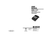
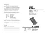
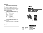
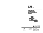
Dear Valued Customer,
USER
MANUAL
Thank you for purchasing Patton Electronics products! We do
appreciate your business. I trust that you find this user manual helpful.
We manufacture one of the widest selections of data communications products in the world including CSU/DSU's, network termination units,
powered and self-powered short range modems, fiber optic modems, interface
converters, baluns, electronic data switches, data-line surge protectors, multiplexers, transceivers, hubs, print servers and much more. We produce these
products at our Gaithersburg, MD, USA, facility, and can custom manufacture
products for your unique needs.
MODEL 2023
Serial to Parallel
Interface Converter
We would like to hear from you. Please contact us in any of the
following ways to tell us how you like this product and how we can meet
your product needs today and in the future.
Web:
Sales E-mail:
Support E-mail:
Phone - Sales
Phone - Support
Fax:
Mail:
http://www.patton.com
[email protected]
[email protected]
(301) 975-1000
(301) 975-1007
(301) 869-9293
Patton Electronics Company
7622 Rickenbacker Drive
Gaithersburg, MD 20879 USA
We are committed to a quality product at a quality price. Patton
Electronics is BABT and ISO 9001 certified. We meet and exceed the highest standards in the industry (CE, UL, etc.).
It is our business to serve you. If you are not satisfied with any
aspect of this product or the service provided from Patton Electronics or its
distributors, please let us know.
Thank you.
Burton A.Patton
Executive Vice President
P.S. Please tell us where you purchased this product:
________________________________________________________
________________________________________________________
________________________________________________________
________________________________________________________
________________________________________________________
________________________________________________________
Part# 07M2023-C
Doc# 020111UC
Revised 08/12/99
An ISO-9001
Certified Company
SALES OFFICE
(301) 975-1000
TECHNICAL SUPPORT
(301) 975-1007
http://www.patton.com
1.0 WARRANTY INFORMATION
1.3 SERVICE
Patton Electronics warrants all Model 2023 components to be
free from defects, and will—at our option—repair or replace the product should it fail within one year from the first date of shipment.
This warranty is limited to defects in workmanship or materials,
and does not cover customer damage, abuse or unauthorized modification. If this product fails or does not perform as warranted, your sole
recourse shall be repair or replacement as described above. Under no
condition shall Patton Electronics be liable for any damages incurred
by the use of this product. These damages include, but are not limited
to, the following: lost profits, lost savings and incidental or consequential damages arising from the use of or inability to use this product.
Patton Electronics specifically disclaims all other warranties,
expressed or implied, and the installation or use of this product shall
be deemed an acceptance of these terms by the user.
All warranty and nonwarranty repairs must be returned freight prepaid and insured to Patton Electronics. All returns must have a Return
Materials Authorization number on the outside of the shipping container. This number may be obtained from Patton Electronics Technical
Service: (301) 975-1007; http://www.patton.com: or, [email protected].
NOTE: Packages received without an RMA number will not be
accepted.
Patton Electronics' technical staff is also available to answer any
questions that might arise concerning the installation or use of your
Model 2023. Technical Service hours: 8AM to 5PM EST, Monday
through Friday.
1.1 RADIO AND TV INTERFERENCE
The Model 2023 generates and uses radio frequency energy, and
if not installed and used properly—that is, in strict accordance with the
manufacturer's instructions—may cause interference to radio and television reception. The Model 2023 has been tested and found to comply with the limits for a Class A computing device in accordance with
the specifications in Subpart J of Part 15 of FCC rules, which are
designed to provide reasonable protection from such interference in a
commercial installation. However, there is no guarantee that interference will not occur in a particular installation. If it does cause interference to radio or television reception, which can be determined by disconnecting the RS-232 interface, the user is encouraged to try to correct the interference by one or more of the following measures: moving the computing equipment away from the receiver, re-orienting the
receiving antenna and/or plugging the receiving equipment into a different AC outlet (such that the computing equipment and receiver are on
different branches).
1.2 CE NOTICE
The CE symbol on your Patton Electronics equipment indicates
that it is in compliance with the Electromagnetic Compatibility (EMC)
directive and the Low Voltage Directive (LVD) of the Union European
(EU). A Certificate of Compliance is available by contacting Patton
Technical Support.
1
2
2.0 GENERAL INFORMATION
3.0 CONFIGURATION
Thank you for your purchase of this Patton Electronics product.
This product has been thoroughly inspected and tested and is warranted for One Year parts and labor. If any questions arise during installation or use of the unit, contact Patton Electronics Technical Support:
(301) 975-1007; http://www.patton.com; or, [email protected].
The Model 2023 is equipped with internal jumpers for data configuration, rate selection and method of handshaking to be used. The
jumper options are summarized in Figure 1 (below). See Table 1 for a
description of the factory settings.
Converts serial data to parallel data
Built-in 16 bit buffer prevents loss of data
Supports both XON/XOFF and hardware flow control
Data rates to 19.2 Kbps
No AC power required
DCE/DTE switch selectable
Small and easy to install
Complete with 6 feet of cable and a Centronics connector
Made in USA
Flow
Control
Jumper
Serial DB-25 Connector
2.1 FEATURES
•
•
•
•
•
•
•
•
•
Data Rate
Jumper
Data Configuration
Jumper
DCE/DTE Switch
2.2 DESCRIPTION
Figure 1. The Location of the Patton Model 2023 Configuration Switches
The Model 2023 Serial to Parallel Converter converts RS-232C
serial data to parallel data. An internal strapping option facilitates
hardware or software flow control by converting the parallel BUSY signal to the relevant signal on the serial interface. It supports serial data
rates to 19.2 Kbps and requires no AC power.
For easy configuration, the Model 2023 features a convenient set
of configuration switches, which allows you to control data rate, parity,
data bits and flow control. The Model 2023 is also DCE/DTE switch
selectable.
Housed in an ultra-miniature ABS plastic case, the Model 2023
measures only 4.17” x 1.73” x .87”. The Model 2023 comes standard
with a DB-25 female connector on the computer side, a Centronics 36
pin male connector on the printer side and a 6 foot connector. Custom
connectors and cable lengths are also available.
3.1 ACCESSING JUMPERS AND SWITCHES
To gain access to the internal jumpers, remove the four screws
on the plastic casing and pull the case halves apart. Be careful not to
lose the four case screws or the captive screws.
3.2 SETTING THE DCE/DTE SWITCH
The internal DCE/DTE switch (shown below) allows the Model
2023 to plug directly into a DB-25 serial interface port without use of a
crossover cable. When connecting the Model 2023 to a PC, terminal
or other DTE, set the DCE/DTE switch to "DCE". When connecting
the Model 2023 to a modem or multiplexer, set the DCE/DTE switch to
"DTE". Refer to Appendix B & Appendix C for specific DCE/DTE pin
designations.
DCE
DTE
Figure 2. Close up of the Patton Model 2023 DCE/DTE Switch
3
4
4.0 INSTALLATION
3.3 SETTING THE JUMPERS
Data Bits: Set the jumper to match the data bit configuration on
your serial communication port.
Parity: Parity bits are sometimes used to enable a limited error
detection scheme. Set the EN/DIS jumper to ENABLE if your serial
communication port uses a parity bit, and to DISABLE if it does not.
Set the ODD/EVEN jumper according to your system's requirements.
Data Rate: Most PC serial communication ports can operate at
speeds up to 9600 bps. Match the data rate to the COM port bit rate.
Hardware Flow Control: In "DCE" mode, when the BUSY line
(pin 11) from the parallel port goes high, CTS (pin 5) and DSR (pin 6)
on the serial port go low: this stops the flow of data. After the buffer
empties, the BUSY line goes low, and CTS and DSR go high. This
allows the serial port to send data. (In "DTE" mode, pins 11, 19 and 20
are used for hardware flow control).
Software Flow Control: In "DCE" mode, whenever BUSY (pin
11) on the parallel interface goes high for more than 5 mSec, an XOFF
command is sent to the serial port to stop data flow. When the BUSY
line turns off, an XON command is sent to allow the serial port to continue transmitting.
After configuring the Model 2023, align the case halves and
replace the four case screws. Then, plug the DB-25 connector (in the
case) into the serial port of your RS-232 device and tighten the brass
screws for a secure connection. Next, plug the Centronics connector
(on the cable end) into your parallel printer and fasten the bail latches
to the corresponding "ears".
Once connected to the proper interface ports, the Model 2023 is
ready to operate. Since the Model 2023 derives power from the serial
interface, there is no "power" switch to turn on and no AC adapter to
plug in. If you are using the Model 2023 in a DOS environment,
please follow the software set-up instructions in Section 4.1 (below).
4.1 DOS SOFTWARE SET-UP
To use the Model 2023 in a standard DOS application, you will
need to set-up the serial COM port on the computer. Make sure the
COM port configuration and the Model 2023 configuration are the
same. To do this you can refer to your DOS manual or see the summary below:
From C> Mode Comn [:] baud [,parity[,data bits[,stop bits[,P]]]]
where n = 1 or 2 [COM port 1 or 2]
Strap Identity
Function
Possible Settings
Factory Setting
baud = 300, 600, 1200, 2400, 4800, 9600
Data Bits
Matches number of data
bits to the printer.
7
8
8 bits
Parity
Determines parity usage.
EN/DIS
EVEN/ODD
Disable
Even
Data Rate
Matches the speed of the
2023 to that of serial input
device.
300
600
1200
2400
4800
9600
19200
H=Hardware
S=Software
Flow Control
NOTE:
NOTE:
Enables CTS/DSR control
or XON/XOFF flow control.
parity = Either N (none), O (odd), or E (even)
(default = E)
data bits = Either 7 or 8 (default = 7)
Note: Graphics files require 8
stop bits = Either 1 or 2 (default = 1)
9600
Hardware
Unit is hardwired for one stop bit
With the jumper removed from the flow control pins, both Hardware and Software flow
control are operative, i.e., XON/XOFF is sent as well as normal control of the CTS/DSR
control lines. This mode is not recommended for most operations.
P = Indicates that the COM port is being used for a printer. If you enter P, time out
errors will be continuously retried.
The following command sets the COM1 for the default configuration of
the Model 2023:
C> MODE COM1:96,N,8,1,P
Table 1. Factory Strap Settings
Note: If your PC or output device requires a different software set-up,
consult the user manual or call Technical Support at (301) 975-1007.
5
6
APPENDIX A
APPENDIX B
PATTON MODEL 2023 SPECIFICATIONS
PATTON MODEL 2023 SERIAL PORT CONNECTIONS
“DCE” SETTING
Serial Interface:
Asynchronous, RS-232C compatible, DB-25
female; DCE/DTE switch selectable
Serial Data Rates:
300, 600, 1200, 2400, 4800, 9600, 19200
bps
Data Format:
Strap selectable: 7 or 8 bits; one stop bit
Parity:
Strap selectable: enable/disable, even/odd
Parallel Interface:
Centronics compatible, 36 pin male
connector attached to the end of a
cable
6 foot
Power:
Uses power from RS-232C interface; no
external power required
Temperature:
0-60°C (32-140°F)
Altitude:
Up to 3000m (10,100 feet)
Pin
Name
Description
1
2
FG
TXD
3
4
5
RXD
RTS
CTS
6
DSR
7
8
9
11
19
20
SG
CD
+V
Frame Ground
Serial Transmit Data; data input from serial port;
input to the 2023 power supply
Serial Receive Data (sends XON/XOFF to serial port)
Request to Send; input to the 2023 power supply*
Clear to Send; used for hardware flow control
ON (high) when parallel BUSY lead is low
OFF (low) when parallel BUSY lead is high
Data Set Ready; used for hardware flow control
connected to CTS line (pin 5 above)
Signal Ground
Carrier Detect; pulled to +V when powered up
Input to the 2023 power supply*
Input to the 2023 power supply;* connected to pin 20
Input to the 2023 power supply;* connected to pin 20
Data Terminal Ready; input to the 2023 power supply*
DTR
“DTE” SETTING
Humidity:
5 to 95% non-condensing
Physical:
4.17" x 1.73" x 0.87"
Pin
Name
Description
1
2
FG
TXD
3
RXD
4
5
6
7
8
9
11
19
20
RTS
CTS
DSR
SG
CD
+V
Frame Ground
Serial Transmit Data; (sends XON/XOFF to serial
port)
Serial Receive Data; data input from serial port
input to the 2023 power supply
Request to Send; pulled to +V when powered up
Clear to Send; input to the 2023 power supply*
Data Set Ready; input to the 2023 power supply*
Signal Ground
Carrier Detect; input to the 2023 power supply*
Input to the 2023 power supply*
Used for hardware flow control; connected to pin 20
Used for hardware flow control; connected to pin 20
Data Terminal Ready; input to the 2023 power supply
ON (high) when parallel BUSY lead is low;
OFF (low) when parallel BUSY lead is high
DTR
*Note: These power inputs are not required for operation.
7
8
APPENDIX C
APPENDIX D
PATTON MODEL 2023 PARALLEL PORT CONNECTIONS
PATTON MODEL 2023 BLOCK DIAGRAM
Pin
Name
Description
1
Strobe
Output; normally high; goes low to
read in data on power-up)
Output
Output
Output
Output
Output
Output
Output
Output
Input; normally high; goes low to
shift next byte out of the buffer
Input; normally low; goes high when
buffer is full; goes low when buffer empties
2
3
4
5
6
7
8
9
10
Data bit 0
Data bit 1
Data bit 2
Data bit 3
Data bit 4
Data bit 5
Data bit 6
Data bit 7
Acknowledge
11
Busy
16
17
19
|
|
30
33
36
Ground
Ground
Ground
Ground
Ground
Ground
*Note: These power inputs are not required for operation.
Copyright ©
Patton Electronics Company
All Rights Reserved
4