1
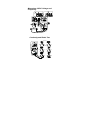
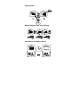
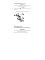
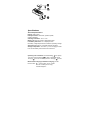
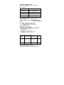
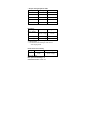
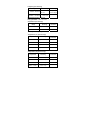
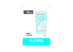
IDM 61/62T
Digital Multimeter
Instruction
Manual
# Safety Information
Read and understand this Instruction Manual completely
before using this instrument. Failure to observe the warnings
and cautions in this Instruction Manual may result in injury or
death, or damage to the instrument and other equipment or
property.
If this instrument is used in a manner not specified in these
instructions, the protection provided by the instrument may be
impaired.
•
•
•
•
•
•
•
•
•
•
•
•
•
•
# WARNING
Examine the instrument and probes before use. Do
not use the instrument if it is wet or damaged.
When using test leads or probes, keep your fingers
behind the finger guards.
Remove the test lead from the instrument before
opening the battery cover or instrument case.
Always use the correct terminals, switch position
and range for measurements.
Never attempt a voltage measurement with the test
leads inserted into the A input terminals.
Verify the instrument is operating correctly by
measuring a known voltage before use. If in doubt,
have the instrument serviced.
Do not apply more than the rated voltage, as
marked on the instrument, between terminals or
between any terminal and earth ground.
Do not attempt a current measurement when the
open-circuit voltage is above the fuse protection
rating.
Only replace a blown fuse with the correct type and
rating as specified in this Instruction Manual.
Use caution when measuring voltages above 30
Vac rms or 60 Vdc. These voltages pose a shock
hazard.
To avoid incorrect readings that can lead to electric
shock, replace the battery as soon as low battery
indicator
appears in the display.
Disconnect the circuit power and discharge all highvoltage capacitors before making resistance,
current,
continuity,
diode
or
capacitance
measurements.
Do not use the instrument in a Hazardous Area or
around explosive gasses or vapours.
Wear suitable Personal Protective Equipment when
working around or near hazardous Live conductors
which could be accessible.
# Caution
․ Disconnect the test leads from the test points before
changing the position of the function rotary switch.
․ Never connect the instrument to a source of voltage with the
function rotary switch in Ω/ :;/∋ %A /</Hz position.
․ If possible, do not work alone, so assistance can
be given if required.
․ Do not expose the instrument to extremes of temperature or
high humidity.
․ Never set the instrument to the ∋ %A function to measure
the voltage of a power supply circuit, as it may result in
damage to the instrument and the equipment under test.
The following symbols may appear on the instrument
and in this Instruction Manual:
∀
Risk of electric shock
#
∋
Refer to Instruction Manual
1
Equipment protected throughout by double or
reinforced insulation
Direct Current (dc)
Battery
&
Fuse
)
%
Earth
6
Conforms to applicable EU directives
Alternating Current (ac)
Maintenance
Do not attempt to repair this Instrument. It contains no
user-serviceable parts. Repair or servicing should only be
performed by qualified personnel. This instrument should be
calibrated yearly, or more frequently if used in harsh conditions
or if it is suspected of being inaccurate.
For calibration and repair contact RS Components - the address
is given at the end of these instructions.
Cleaning
Periodically wipe the case with a damp cloth and
detergent. Do not use abrasives or solvents.
Measuring AC/DC Voltage and
Frequency
Continuity and Diode Test
Bad Diode
Red
Black
Red
Black
Good Diode
Red
Black
Red
Black
Resistance and Capacitance Measurement
(Capacitance for 62T only)
Note– To improve the measurement accuracy of a small
value capacitor, record the reading with the test leads
open circuit, then substract the residual capacitance of the
Instrument and leads from the final measurement.
CUNKNOWN = CMEASUREMENT - CRESIDUAL
MIN MAX Record (For 62T only)
Measuring DC / AC Current
(For 62T only)
Temperature °C , °F
Display Hold
Manual Ranging and Auto Ranging
Auto Power-off (Battery Saver)
10 min
Disable Auto Power-off
Non-Contact Voltage Sensing (VoltSense)
NCV
1. The VoltSense function will operate irrespective of the
position of the function rotary switch, including the OFF position.
2. Remove the test leads from the instrument as they are not
used for the VoltSense test.
3. Press and hold the VoltSense button. The LCD display will go
blank, a tone will sound and the red LED will illuminate
momentarily to confirm the instrument is operational.
4. Hold the Volt sense button down and move the instrument
over the area where detection is required. The buzzer will sound
and the LED will illuminate when a live conductor is detected.
Release the VoltSense button to return to normal operation.
Fuse Replacement (For 62T only)
∀ Warning
Disconnect the test leads from the circuit and the instrument
before removing the rear cover.
# Caution
Use only a replacement fuse of the type and rating given in the
specifications.
Refer to the following figure to replace the fuse:
Battery Replacement
When the low battery indicator " " appears on the LCD, replace
the batteries with the type given in the specifications.
∀ WARNING
Disconnect the test leads from the circuit and the instrument
before removing the battery cover.
Refer to the following figure to replace the batteries:
Specifications
General Specifications
Display: 2000 counts.
Polarity Indication: Automatic, positive implied,
negative indicated.
Overrange Indication: “OL” or “-OL”.
Battery Life: 250 hours approx with Alkaline cells.
Low Battery Indication: “ ” is displayed when
the battery voltage drops below the minimum operating voltage.
Auto Power-off: Approx 10 minutes after last operation.
Storage Temperature: -20 to 60°C (-4°F to 140°F) @ 0 to 80%
R.H. with the battery removed from the instrument.
Operating environmentent: Non-condensating, ≦ 10°C (50°F);
11 to 30°C (51.8°F to 86°F) @ ≦80% R.H; 31 to 40°C (87.8°F to
104°F) @ ≦75% R.H; 41 to 50°C (105.8°F to 122°F) @ ≦45% R.H.
Measurement Category (Installation Category) per IEC
61010-1:2001: V/Ω: CAT.III. 600V, CAT.II. 1000V.
A: CAT.III. 600V (for 62T only)
Pollution Degree 2
Measurement Category l is for measurements performed on
circuits not directly connected to mains. Examples include:
Measurements on battery powered equipment and specially
protected (internal) mains-derived circuits.
Measurement Category ll is for measurements on circuits
directly connected to the low voltage installation. Examples
include: Household appliances, portable tools and similar
equipment.
Measurement Category lll is for measurements performed in
the building installation. Examples include measurements on
distribution boards, junction boxes, socket-outlets and wiring
and cables in the fixed installation.
Measurement Category lV is for measurements performed at
the source of the low-voltage installation. Examples include
measurements on primary overcurrent protection devices and
electricity meters.
Temperature Coefficient:
0.27 x Spec. Accy / °C <18°C or >28°C; (0.15 x Spec.Accy / °F,<
64.4°F or > 82.4°F).
Power Requirements:
Qty. 2 x 1.5V Alkaline type AA batteries.
Fuse (For 62T only): 10mmx38 mm 10Amp 600V ac/dc HBC,
Littlefuse KLKD10 or equivalent.
Dimensions (W x H x D): 74mm x 156mm x 44mm
Accessories: Battery (installed), Test leads and user manual.
Measurement rate: Sampling rate 2 times per second nominal.
Altitude: 6561.7 ft (2000m)
Safety: Complies with EN61010-1:2001, UL61010-1:2001 and
IEC 61010-1:2001.
Weight: (320g) including battery.
Electrical Specifications
Accuracy is ±(% reading + number of digits) at
23°C ± 5°C < 80%RH.
DC / AC Volts
Range
AC Accuracy
200.0mV *
Unspecified
2.000V *
±(1.5%+5dgt)
20.00V ~ 200.0V * ±(1.5%+5dgt)
50Hz ~ 300Hz
50Hz ~ 500Hz *
750V AC / 1000V DC
DC Accuracy : ±(0.5% + 2dgt)
Over voltage protection : 1000V DC or 750 V ACrms.
Input Impedance : 10MΩ // less than 100pF.
* CMRR / NMRR : (Common Mode Rejection Ratio)
(Normal Mode Rejection
Ratio)
VAC : CMRR > 60dB at DC, 50Hz / 60Hz
VDC : CMRR > 100dB at DC, 50Hz / 60Hz
NMRR > 50dB at DC, 50Hz / 60Hz
AC Conversion Type :
Average sensing rms indication.
AC conversions are ac-coupled, true rms responding,
calibrated to the sine wave input.
* The minimum LCD reading is 1400 count in Auto
Ranging Mode.
Crest Factor: C.F. = Peak / Rms
+ 1.5% addition error for C.F. from 1.4 to 3
+ 3% addition error for C.F. from 3 to 4
DC / AC Current
Range
2.000A
(For 62T only)
DC Accuracy
±(1.0% + 3 dgt)
AC Accuracy
Voltage
Burden
±(1.5% + 5 dgt)
50Hz ~
2V max
500Hz
*
10.00A **
Overload Protection:
A input : 10A (500V) fast blow fuse
* AC Conversion Type : Conversion type and
additional specification are same as DC/AC Voltage.
** Ampere Testing Duty Ratio Table
Ampere
Testing Time
Rest Time
10A
4min
10min
9A
5min
10min
8A
7min
10min
7A
10min
10min
6A
Continuous
N/A
Accuracy
Voltage Burden
Resistance
Range
200.0 ~ 200.0KΩ
±(0.7% + 3 dgt)
2V max
**
2.000MΩ
**
±(1.0% + 3 dgt)
20.00MΩ
*
±(1.5% + 3 dgt)
Open circuit Voltage: -1.3V approx.
* <100 dgt rolling.
* * The minimum LCD reading is 1400 count in
Auto-ranging mode.
Diode Check and Continuity
Range
Resolution
Accuracy
:
10 mV
±(1.5% + 5 dgt)*
* For 0.4V ~ 0.8V
Max.Test Current : 1.5mA
Max. Open Circuit Voltage : 2V
Overload Protection : 600V rms.
Frequency (For 62T only)
Range
2000Hz ~200.0KHz
2.000MHz ~ 20.00MHz
Sensitivity
Accuracy
>1.5 Vac rms, <5 Frequency :
0.01%±1digit
Vac rms
>2 Vac rms,
<5 Vac rms
Overload Protection: 600V rms.
Minimum pulse width: >25 ns
Duty cycle limits: >30% and <70%
Capacitance (For 62T only)
Range
Accuracy
Overload
Protection
2.000nF ~ 200.0µF
±(1.9% + 8 dgt)
600V rms
2.000mF *
* < 10 dgt of reading rolling.
Temperature (°C ) (For 62T only)
Temperature
Accuracy
Overload
Protection
-20°C ~ 0°C
±(2% + 4°C )
600V rms
1°C ~ 100°C
±(1% + 3°C )
101°C ~ 500°C
±(2% + 3°C )
501°C ~ 800°C
±(3% + 2°C )
Temperature (°F ) (For 62T only)
Accuracy
Overload
Protection
-4°F ~ 32°F
±(2% + 8°F)
600V rms
33°F ~ 212°F
±(1% + 6°F)
213°F ~ 932°F
±(2% + 6°F)
933°F ~ 1472°F
±(3% + 4°F)
Temperature
Limited Warranty
This instrument is warranted to the original purchaser against
defects in material and workmanship for 1 year from the date of
purchase. During this warranty period, RS Components will, at its
option, replace or repair the defective unit, subject to verification of
the defect or malfunction. This warranty does not cover disposable
batteries, or damage from abuse, neglect, accident, unauthorized
repair, alteration, contamination, or abnormal conditions of
operation or handling.
Any implied warranties arising out of the sale of this product,
including but not limited to implied warranties of merchantability and
fitness for a particular purpose, are limited to the above. RS
Components shall not be liable for loss of use of the instrument or
other incidental or consequential damages, expenses, or economic
loss, or for any claim or claims for such damage, expense or
economic loss. Some states or countries laws vary, so the above
limitations or exclusions may not apply to you. For full terms and
conditions, refer to the current RS Catalogue.
United Kingdom:
RS Components UK
PO Box 99, Corby,
Northants.,
NN17 9RS
Tel: 01536 201234
Fax: 01536 405678
http://rswww.com
Deutschland:
RS Components GmbH
Hessenring 13b
64546 Mörfelden-Walldorf
Telefon: 06105/401-0
Fax: 06105/401-100
http://www.rsonline.de
España:
RS Amidata SA
Parque Empresarial Urbis Center
Avda de Europa 19 – Edificio 3
28224 Pozuelo de Alarcón
Madrid
España
Tel: (34) 902 10 07 11
http://www.amidata.es
Italia:
RS Components SpA
Via M.V. De Vizzi 93/95
20099 Cinisello Balsamo (Mi)
tel: +39 02 66058.1
fax: +39 02 66058.051
http://www.rs-components.it
Francais:
Radiospares Composants SNC
Rue Norman King
BP453
F-60031 Beauvais Cedex
France
Tel: (33) 3 44 10 1500
Fax: (33) 3 44 10 1507
http://www.radiospares.fr