1
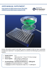
KIM HINTS
Since you and your KIM-1 are relative strangers, we'd like to help
you get better acquainted. The material in this pamphlet will
answer questions that are frequently asked by a new KIM-1 user.
. ANSWERS TO POPULAR KIM SYSTEM QUESTIONS
1.
IS IT POSSIBLE TO OUTPUT DIGITS OTHER THAN
HEX TO THE 6 OUTPUT LED'S?
Since the 6502 is doing all segment decode and multiplex, it is possible to display data other than hex on a
7-segment readout. A pseudo alphabet has been developed and is displayed in the 7-segment display of the
KIM in a scrolling manner.
2. WHEN HANDLING THE BOARD, WOULD THE
STATIC HAZARD BE R E L I E V E D IF ALL EDGE
CONNECTORS WERE SHORTED TOGETHER?
The static problems are not as serious once the devices
are installed in the P.C. board. Just be sure to use
grounded tools and to discharge yourself to ground
before touching KIM or the connected circuits.
3.
WHAT TYPE OF LED READOUT IS USED ON
KIM-1 FOR U18, etc?GENERAL COMMON ANODE
OR CATHODE?
USE MAN-72 Type displays, available from many manufacturers. General common anodes should work,
although you may find intensity differences between
them.
4.
WHERE CAN I GET MORE 44-PIN EDGE CONNECTORS FOR KIM?
The connector is a standard part —you can order a
Vector No. R644 from most electronic supply houses.
The connector is also carried by most Radio Shack
stores as Part No. 276-548.
5.
ARE THERE ANY INTERFACES OR PROM PROGRAMMERS AVAILABLE WITH KIM TO PROGRAM
EPROMs OR TO DUPLICATE PROMs?
No, not yet.
6.
IS THERE AN I/O EXPANSION BOARD AVAILABLE?
Not yet . . . soon, we hope.
7.
IS THERE A BOARD AVAILABLE TO MAKE USE
OF MEMORY ADDRESSES 0400-13FF?
Check the "Kilobaud" article (issue #4, April 1, 1977,
page 74) entitled "KIM Memory Expansion."
8.
HOW DO I SET UP MY KIM FOR AUDIO CASSETTE
RECORDING AND PLAYBACK?
A number of KIM-1 customers have reported difficulty
in achieving correct results for the sample problem
shown in Sec. 2.4 of the KIM-1 User Manual. In addition, some customers have experienced problems in
recording or playback of audio cassettes. (Sec. 2.5 of
the KIM-1 User Manual). In all cases, the problems
have been traced to a single cause: the inadvertent
setting of the DECIMAL MODE.
The 6502 Microprocessor Array used in the KIM-1
system is capable of operating in either binary or
decimal arithmetic mode. The programmer must be
certain that the mode is selected correctly for the program to be executed. Since the system may be in
either mode after initial power-on, a specific action is
required to insure the selection of the correct mode.
Specifically, the results predicted for the sample
problem (Sec. 2.4) are based on the assumption that
the system is operating in the binary arithmetic mode.
To insure that this is the case, insert the following
key sequence prior to the key operations shown at the
bottom of Page 11 of the KIM-1 User Manual.
AD/
This sequence resets the decimal mode flag in the Status Register prior to the execution of the sample
program.
The same key sequence may be inserted prior to the
key operations shown on pages 14 and 15 for audio
cassette recording and playback. These operations
will not be performed correctly if the decimal mode is
in effect.
In general, whenever a program is to be executed
in response to the /GO/ key, the programmer should
insure that the correct arithmetic mode has been set in
the status register (OOF1) prior to program execution.
HOW DO I SOLVE AUDIO CASSETTE INTERFACE
PROBLEMS?
A. Insure that memory location OOF1 has been set to a
value of 00 before recording or playing back the tape.
This is the source of 90% of all cassette problems.
B. Mis-adjustment of the variable resistor ( V R 1 ) in the
cassette circuitry is almost never a problem. Any
setting near the center of its rotation will work fine.
C. Make sure that +12V is connected during playback.
NOTE: +12V is not required for recording, so a lack
of +12V will result in good recording but no playback.
D. If the display frequently relights showing FFFF,
the fault is probably in the tape unit itself — not the
KIM. Using poor quality cassettes is usually to blame.
Some cassette recorders have such poor power filtering
circuits that they will work fine on batteries, but will
not work with an AC adapter because of hum induced
during record or playback. Tapes should always be
rewound before removal from the machine, as a fingerprint on the tape will result in errors on playback.
E. Make sure that only a single ground line is run from
the KIM ground to the barrel of the microphone input
of the cassette recorder. Leave the barrel of the earphone output ungrounded. The shield around the line
to the earphone should be attached to ground on KIM.
F. Problems of playing a tape recorded on one KIM
system back on another system or a different cassette
player can usually be solved by adjusting the head
adjustment screw on the new cassette recorder. Play
back a cassette recorded on the old deck on the new
machine and adjust the head screw on the new machine
for maximum volume. This adjustment is especially
critical when using the SuperTape program.
10. HOW DO I SOLVE TELETYPE PROBLEMS?
A. The most common problem is that the system does
not respond to a reset-rubout sequence with a model
33 Teletype. This can be fixed by removing the wire
connected to pin R on the KIM application connector,
connecting a 470 ohm resistor to that wire, and connecting the other end of the resistor to the +12V
supply at pin N.
11. HOW DO I SOLVE PAPER TAPE PROBLEMS?
A. KIM-1 's having a date code in 1975 on the 6502
will not read paper tape correctly. These CPU's will
be replaced by MOS without charge. Tom Pittman's
TINY BASIC will not work on these machines either.
The problem occurs because early versions of the processor did not set the zero flag correctly on TXA,
TYA, TAX, or TAY instructions.
B. When using a Texas Instruments Silent 700 data
terminal equipped with digital cassettes or other higherspeed paper tape devices, a Q (paper tape dump) may
be performed at any speed acceptable to the data
terminal, but playback (through the L command) must
be at 10 cps.
12. WHAT DO I DO ABOUT OTHER PROBLEMS?
A. If the RESET on KIM causes only a single digit or
segment to light on the display, the KIM must be
returned for repair.
B. When in doubt, check all power supply voltages
on the KIM board, not at the power supply terminals.
C. When software works strangely or erratically,
decimal/binary mode problems may be involved.
D. There is an error in the KIM Resident Assembler
manual regarding the addresses for the symbol table
vectors. The vector locations are DF, EO, E1, E2. The
text is incorrect, the example is correct.
E. Problems with KIM-2/3's which fail the memory
test program can almost always be traced to excessive
cable length between the KIM-1 and the KIM-2/3.
Any cable should be 6" in length or less.
13. WHAT ARE THE KIM SYSTEM POWER SUPPLY
REQUIREMENTS?
KIM
-> TO + 12 v
N
KIM 1 — Microcomputer Board:
470
-X-
Recommended:
TO TELETYPE KEYBOARD
B. No information is available on connecting other
Teletype models (14, 28, 32) to KIM.
C. Schematics for interfacing KIM to an RS232C port
are in the April, 1976 "Byte" magazine and in the first
issue of the KIM user notes. (Reproduced below):
1.2A
+5V ±5%
100mA +12V±5%
The actual power measured ranges 700 mA to 1A at
+5V and the schematic indicating 3A at transformer
is incorrect.
KIM 3A-8K RAM Memory Board:
Recommended:
+5V, 3A
Average consumption calculated is about 2.4A.
Board has +5V regulator accepting unregulated +8 to
+10V DC.
KIM 4-Mother Board:
Consumption about 200mA. Board has +5V regulator accepting unregulated +8 to + 10V DC and
+12V regulator accepting unregulated +15V DC
to support both KIM1 and KIM 4. KIM 4 has 6 slots
for memory expansion with KIM2 and KIM3 and
hence a total power supply requirement is a cumulative value dependent on KIM-System configuration.
D. Other common sources of Teletype problems are a
short circuit in C5 or a burned-out Q7. Signal tracing
with a 'scope should reveal these problems.
14. WHAT SOFTWARE IS AVAILABLE?
The following software is available for use with the
KIM-1 and/or other 6502-based systems:
1. Tiny BASIC - runs in 2K. $5 for paper tape from:
Tom Pittman
Box 23189
San Jose, California 95153
8. A 4K version of FOCAL, a BASIC-like interpreter, and
a 6K Resident assemble/text Editor, both with source
listings and object code on KIM cassette or paper tape
are available from:
ARESCO
314 Second Ave.
Haddon Heights, NJ 08035
The FOCAL is $50 and the assembler/Editor is $70.
A complete information package is $2.
2. Many games and other information in the KIM-1
User Group Newsletter, $5 for 6 issues:
Eric Rehnke
109 Centre Avenue
W. Norriton, PA 19401
9. An 8K version of BASIC for KIM is available for $99
from:
Johnson Computing
123 W. Washington St.
Medina, Ohio 44256
(215) 725-4568
3. An excellent Chess playing program which runs
in 1K. $10
MICRO CHESS
27 Firstbroke Rd.
Toronto, CANADA M 4E 2L2
4. A good group of games plus an intermediate-level
language called PLEASE for KIM-1 - $15 from:
10. "FIRST BOOK OF KIM" is a collection of games,
utility programs, hints and kinks, etc. (180 pgs).
$9.00 plus 50d postage from:
ORB
P.O. Box 311
Argonne, ILL 60439
THECOMPUTERIST
Post Office Box 3
S. Chelmsford, MA 01824
5. The 6502 Program Exchange
2920 Moana
Reno, NV 89509
6. Micro Software Specialists
2024 Washington Street
Commerce, TX 75428
INTERVAL TIMER OPERATION
7. KIMATH, a complete floating-point math package including both source and object code is available from
MOS Technology for $15.
a. Loading the timer
The divide rate and interrupt option enable/disable are programmed by decoding the least significant address bits.
1.
OPERATION
KIM SUBROUTINES
The starting count for the timer is determined by the value
written to that address.
Writing
to Address
Sets Divide
Ratio To
Interrupt
Capability Is
1704
1705
1706
1707
170C
1
8
64
1024
1
Disabled
Disabled
Disabled
Disabled
Enabled
b.
170D
8
Enabled
170E
170F
64
1024
Enabled
Enabled
Determining the timer status
2. CAPABILITIES
The KIM Interval Timer allows the user to specify a preset
count and a clock divide rate by writing to a memory location. As soon as the write occurs, counting at the specified
rate begins. The timer counts down at the clock frequency
divided by the divide rate. The current timer count may be
read at any time. At the user's option the timer may be
programmed to generate an interrupt when the counter
counts down past zero. When a count of zero is passed, the
divide rate is automatically set to 1 and the counter continues to count down at the clock rate starting at a count of
FF (-1 in two's complement arithmetic). This allows the
user to determine how many clock cycles have passed since
the timer reached a count of zero. Since the counter
never stops, continued counting down will reach 00 again
then FF, and the count will continue.
After timing has begun, reading address location 1707 will
provide the timer status. If the counter has passed the
count of zero, bit 7 will be set to 1, otherwise, bit 7 (and
all other bits in location 1707) will be zero. This allows
a program to "watch" location 1707 and determine when
the timer has timed out. Note that reading 1707 provides
an entirely different function from writing the same location.
c. Reading the count in the timer
If the timer has not counted past zero, reading location
1706 will provide the current timer count and disable the
interrupt option; reading location 170E will provide the
current timer count and enable the interrupt option. Thus
the interrupt option can be changed while the timer is
counting down. Note that you read 1706 or 170E regardless of which location (1704-OF) was written to start
the timer.
If the timer has counted past zero, reading either memory
location 1706 or 170E will restore the divide ratio to its
previously programmed value, disable the interrupt option
and leave the timer with its current count.
d.
Using the interrupt option
In order to use the interrupt option described above, line
PB7 (application connector, pin 15) should be connected to
either the IRQ (Expansion Connector, pin 4) or NMI (Expansion Connector, pin 6) pin depending on the desired
interrupt function. PB7 should be programmed as an
input line (it's normal state after a RESET).
NOTE
If the programmer desires to use PB7 as a normal I/O line, the programmer is responsible for
disabling the timer interrupt option Iby writing
or reading address 1706) so that it does not
interfere with normal operation of PB7. Also,
PB7 was designed to be wire-ORed with other
possible interrupt sources; if this is not desired,
a 5.1 K resistor should be used as a pull-up
from PB7 to +5v. (The pull-up should NOT be
used if PB7 is connected to NMI or IRQ.)
3.
INTERVAL TIMER AND KEYBOARD
OPERATION
The following three programs show the use of the interval
timer, keyboard and seven segment displays in user programs.
The first program loads a value of 50 in the timer and waits
for it to time out, repeats the process and then increments
the count in the display register (OOFA and OOFB) and
calls the display subroutine SCANS. The process then
repeats.
The second program performs the same function as the first,
but uses the timer to provide interrupts, rather than watching
the timer status register (1707). Thus this program is constantly cycling through the display program SCANS except
when the timer generates an interrupt. When an interrupt
occurs the interrupt service routine (starting at location
010C) resets the timer, increments the display register and
returns to the display program. Note that the LED display
is brighter when using this program because most of the
computer's time is spent displaying rather than watching the
timer.
The third example program demonstrates the use of the
keyboard and display. Any key depressed will appear in
the rightmost digit of the display and will be shifted to the
left with each successive keyboard entry.
Notice that the SCANS routine not only displays the contents of OOF9, OOFA and OOFB but also returns with the
Z flag set to 0 if a key is currently depressed. The GET-
KEY routine is then called to determine which key has
been depressed. Since the SCANS subroutine takes several
milliseconds, a call to this routine can be used to "waste
time" and let any keybounce stop.