1
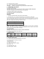
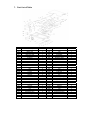
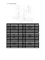
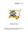
Operating Instructions Parts List TFD35 Lift Table Note: Owner and operator MUST read and understand this operating instructions before use this lift table. Thank you for using this lift table. Your lift table is made of high quality steel and is designed for the horizontal lifting and transport of loads on a level, fixed base. For your safety and correct operation, please carefully read this instruction before using it and keep it on file for future reference. NOTE: All of the information reported herein is based on data available at the moment of printing. We reserves the right to modify our own products at any moment without notice and incurring in any sanction. So, it is suggested to always verify possible updates. 1. WARNINGS 1、 DO NOT put foot or hand in scissors mechanism. 2、 DO NOT allow other person to stand in front or behind lift table when it is moving. 3、 DO NOT move lift table when table is in raised position. Load could fall down. 4、 DO NOT enter under table. 5、 DO NOT overload lift table. 6、 DO NOT put foot in front of rolling wheels, Injury could fall down. 7、 WATCH difference of floor level when moving lift table. Load could fall down. 8、 DO NOT use lift table on slope or inclined surface, lift table may become uncontrollable and create danger. 9、 DO NOT lift people. People could fall down and suffer severe injury. 2. CAUTION 1、 Read this operation manual carefully and understand completely operating lift table. Improper operation could create danger. 2、 This lift table is a movable lifter designed to lift or lower rated load on table. DO NOT use lift table for other purpose than its intended use. 3、 DO NOT allow person to operate lift table that dose not understand its operation. 4、 DO NOT lower table too fast. Load could fall down and create danger. 5、 KEEP watching the condition of load. Stop operating lift table if load becomes unstable. 6、 Braking lift table when sliding load on or off table. 7、 DO NOT side or end load. Load must be distributed on at least 80% of table area. 8、 DO NOT use lift table with unstable, unbalanced loosely load. 9、 Practice maintenance work according to service instructions. 10、DO NOT modify lift table without manufacturers written consent. 11、REMOVE load from table and use safety stopper to prevent table from lowering when servicing lift table. 12、This lift table is not designed to be water resistant. Use lift table under dry condition. 3. DAILY INSPECTION Daily inspection is effective to find the malfunction or fault on lift table. Check lift table on the following points before operation . (1) Check for scratch, bending or cracking on the lift table. (2) Check if there is any oil leakage from the cylinder. (3) Check the vertical creep of the table. (4) Check the smooth movement of the wheels. (5) Check the function of brake. (6) Check if all the bolts and nuts are tightened firmly. CAUTION: DO NOT use lift table if any malfunction or fault is found. 4. OPERATING LIFT TABLE 4-1. How to use the brake. CAUTION: Brake lift when not moving it in order to prevent sudden movement. The brake is equipped with the swivel caster on the right side. (1) Brake the wheel, press the brake pedal. (2) Release the brake, lift up the brake pedal. 4-2.Lifting the table WARNING 1. DO NOT overload lift table. Stay within its rated capacity. 2. DO NOT side or end. Load must be distributed on at least 80% of table area. Press the lifting pedal several times until the table reaches the desired position. The table does not elevate after reaching the highest position even if the lifting pedal is pressed. The table lowers slightly after reaching the highest position. MAXIMUM CAPACITY OF TABLE TFD35 350Kg NOTE: The hydraulic cylinder is designed to hold table. As is the nature of hydraulic system, table lowers very slowly over and extended period of time. Please note the table does not stay at the same position indefinitely. 4-3.Lowering table WARNING: DO NOT put foot or hand in scissors mechanism Pull the control handle make table down.. 5. Specifications Model Capacity (kg) Table (mm) Table Height (mm) Wheel (mm) Weight (Kg) TFD35 350 910x500 355-1300 125 102 USA type before /. European type behind /. 6. Service Instructions 6-1. Lubricate each point described below every month: 6-2. Change hydraulic oil every 12 months. Lubricating Points (1) Fitting of cylinder---Oil (2) Roller friction surface---Grease (3) Link pin ---Oil (4) Pedal fitting point---Oil (5) Grease nipple---Grease 7. Part List of Table No 101M 102 103 104 105 106 107 108 109 110M 111M 112M 113 114 118 119D 120 121 122 123 124 125 126D 127 128 129 130D 131 132 133D 134 135 Description Handle Grip Control Handle Elastic Pin Nut Bolt with Hole Jacket Pull Rod Bolt Washer Big Washer Elastic Washer Bolt Elastic Washer Nut Universal Wheel Frame Pin Washer Axle Bearing Wheel Retaining Ring Pump Unit Pin Washer Retaining Ring Pin Washer Retaining Ring Connecting Rod Cushion Bolt Qty. 1 1 1 1 1 1 1 8 16 2 2 2 8 8 2 1 2 4 2 4 2 2 1 1 1 1 1 2 2 1 1 1 No 136 137 138 139 140 141D 142 143 144 145 146 147 148 149 150 151D 152 153 154 156D 157 158 159 160D 161D 162D 163D 164D 165 166 167 Description Washer Elastic Washer Nut Protecting Cover Pedal Bar Table Retaining Ring Roller Washer Roller Pin Bushing Retaining Ring Pin Retaining Ring Fork Arm Bushing Pin Retaining Ring Washer Support Plank Nut Screw Long Shaft Washer Washer Nut Top Fork Arm Protecting board Bolt Bushing Qty. 1 1 1 1 1 1 2 2 2 2 2 2 2 1 2 1 8 2 2 4 2 2 2 2 4 4 4 1 1 4 2 8. Part List of Pump No 201 202D 203D 204D 205D 206 207 208 209 210 211D 212 214D 217D 220D 221 222 223 224 225 226 227 228 229 230 231 232 237 238 239 Description Seal Washer Pump Cylinder Dust Ring Y-Seal Pump Piston Spring Spring Cap Retaining Ring Joint Plate Pin Pump Body Elastic Pin Strke Pin O-Ring Lever Plate Nut Elastic Washer Washer Bolt With Hole Bolt With Hole Nut Adjusting Bolt O-Ring Spring Seat of Steel Ball Steel Ball Steel Ball Seal Washer O-Ring Seal Washer Qty. 1 1 1 1 1 1 1 1 2 1 1 1 1 2 1 1 1 1 1 1 1 1 1 1 1 1 1 1 1 No 240 241 242 243 244 245 246 247 248 249 250 251 252 253 254 256 257 258 259 260 261 262 263 264 265 266 267 268 269 Description Cylinder Housing Bolt Seal Washer Retaining Ring Washer O-Ring Cup Packing Piston O-Ring Piston Rod Seal Washer Cylinder Cap O-Ring Dust Ring Steel Ball Steel Ball Spring Steel Ball Screw Cup Seat of Steel Ball Spring Seat of Valve O-Ring Spring Core of Valve Retaining Ring Plug Qty. 1 1 1 1 1 1 1 1 1 1 1 1 1 1 1 1 1 1 1 1 1 1 1 1 1 1 1 1 1 ATTENTION: 1. The worn batteries and accumulators were solid wastes with danger.They are harmful to our health and environment. to avoid polluting with the leaking liquid,we should put the replacements into a special and leak-tight container.To avoid the hurt to people,it should be put away from the place people lived and worked with a warning sticker.The collected worn batteries and accumulators should be handed in to a competent institution according to the local statute. 2. The waste packages should be sorted and put into solid dustbins according to the materials and be collected disposal by local special environment protection bureau. To avoid pollution, it’s forbidden to throw away the wastes random. 3. To avoid leaking during the use of the products, the user should prepare some absorbable materials (scraps of wooden or dry duster cloth) to absorb the leaking oil in time. To avoid second pollution to the environment, the used absorbable materials should be handed in to the special department in term of the local statute.