1
MELSEC iQ-R Analog-Digital Converter Module/
Digital-Analog Converter Module Function Block
Reference
CHAPTER 1
FUNCTION BLOCK (FB) LIST
2
CHAPTER 2
ANALOG-DIGITAL CONVERTER MODULE FB
4
2.1
M+R60AD(G)_RequestSetting . . . . . . . . . . . . . . . . . . . . . . . . . . . . . . . . . . . . . . . . . . . . . . . . . . . . . . . . . . . . . . 4
2.2
M+R60AD(G)_OperateError . . . . . . . . . . . . . . . . . . . . . . . . . . . . . . . . . . . . . . . . . . . . . . . . . . . . . . . . . . . . . . . . 6
2.3
M+R60AD(G)_SetLoggingParam . . . . . . . . . . . . . . . . . . . . . . . . . . . . . . . . . . . . . . . . . . . . . . . . . . . . . . . . . . . . 8
2.4
M+R60AD(G)_SaveLogging . . . . . . . . . . . . . . . . . . . . . . . . . . . . . . . . . . . . . . . . . . . . . . . . . . . . . . . . . . . . . . . 12
CHAPTER 3
DIGITAL-ANALOG CONVERTER MODULE FB
17
3.1
M+R60DA(G)(16)_RequestSetting . . . . . . . . . . . . . . . . . . . . . . . . . . . . . . . . . . . . . . . . . . . . . . . . . . . . . . . . . . 17
3.2
M+R60DA(G)(16)_OperateError . . . . . . . . . . . . . . . . . . . . . . . . . . . . . . . . . . . . . . . . . . . . . . . . . . . . . . . . . . . . 19
3.3
M+R60DA_WaveOutputSetting . . . . . . . . . . . . . . . . . . . . . . . . . . . . . . . . . . . . . . . . . . . . . . . . . . . . . . . . . . . . 21
3.4
M+R60DA_WaveDataStoreCsv . . . . . . . . . . . . . . . . . . . . . . . . . . . . . . . . . . . . . . . . . . . . . . . . . . . . . . . . . . . . . 24
3.5
M+R60DA_WaveDataStoreDev . . . . . . . . . . . . . . . . . . . . . . . . . . . . . . . . . . . . . . . . . . . . . . . . . . . . . . . . . . . . . 27
3.6
M+R60DA_WaveOutputReqSetting . . . . . . . . . . . . . . . . . . . . . . . . . . . . . . . . . . . . . . . . . . . . . . . . . . . . . . . . . 30
APPENDICES
CONTENTS
CONTENTS
34
Appendix 1 CSV File Output Format of the FB for Saving Logging Data . . . . . . . . . . . . . . . . . . . . . . . . . . . . . . . . 34
Appendix 2 Storage Source "Parameter/Data of Waveform Output Function" and Storage Destination Buffer
Memory . . . . . . . . . . . . . . . . . . . . . . . . . . . . . . . . . . . . . . . . . . . . . . . . . . . . . . . . . . . . . . . . . . . . . . . . . . . 36
Appendix 3 CSV File Format of the FB for Reading Wave Data (CSV File). . . . . . . . . . . . . . . . . . . . . . . . . . . . . . . 38
INSTRUCTION INDEX
40
REVISIONS . . . . . . . . . . . . . . . . . . . . . . . . . . . . . . . . . . . . . . . . . . . . . . . . . . . . . . . . . . . . . . . . . . . . . . . . . . . . . .42
1
1
FUNCTION BLOCK (FB) LIST
This FB list is intended for those who use the MELSEC iQ-R series analog-digital converter module and digital-analog
converter module.
Analog-digital converter module FB
■R60AD4, R60ADV8, R60ADI8
Name*1
Description
M+R60AD_RequestSetting
Enables the settings of each function.
M+R60AD_OperateError
Monitors error codes and resets errors.
M+R60AD_SetLoggingParam
Sets up the logging function of a specified channel.
M+R60AD_SaveLogging
Saves the logging data of a specified channel into a file.
*1
An FB name ends in the FB version information such as "_00A"; however, this reference manual leaves out it.
■R60AD8-G, R60AD16-G
Name*1
Description
M+R60ADG_RequestSetting
Enables the settings of each function.
M+R60ADG_OperateError
Monitors error codes and resets errors.
M+R60ADG_SetLoggingParam
Sets up the logging function of a specified channel.
M+R60ADG_SaveLogging
Saves the logging data of a specified channel into a file.
*1
An FB name ends in the FB version information such as "_00A"; however, this reference manual leaves out it.
Digital-analog converter module FB
■R60DA4, R60DAV8, R60DAI8
Name*1
Description
M+R60DA_RequestSetting
Enables the settings of each function.
M+R60DA_OperateError
Monitors error codes and resets errors.
M+R60DA_WaveOutputSetting
Sets the waveform output of a specified channel or all channels.
M+R60DA_WaveDataStoreCsv
Reads out data from the CSV file that holds the parameters and the waveform data (number of waveform data points
and waveform data) of the waveform output function, and writes the data to the buffer memory of the digital-analog
converter module.
M+R60DA_WaveDataStoreDev
Reads out data from the file register (ZR) that holds the parameters and the waveform data (number of waveform
data points and waveform data) of the waveform output function, and writes the data to the buffer memory of the
digital-analog converter module.
M+R60DA_WaveOutputReqSetting
Specifies whether to start, stop, or pause the waveform output of a specified channel or all channels.
*1
An FB name ends in the FB version information such as "_00A"; however, this reference manual leaves out it.
■R60DA8-G
Name*1
Description
M+R60DAG_RequestSetting
Enables the settings of each function.
M+R60DAG_OperateError
Monitors error codes and resets errors.
*1
An FB name ends in the FB version information such as "_00A"; however, this reference manual leaves out it.
■R60DA16-G
Name*1
Description
M+R60DAG16_RequestSetting
Enables the settings of each function.
M+R60DAG16_OperateError
Monitors error codes and resets errors.
*1
2
An FB name ends in the FB version information such as "_00A"; however, this reference manual leaves out it.
1 FUNCTION BLOCK (FB) LIST
MEMO
1
1 FUNCTION BLOCK (FB) LIST
3
2
ANALOG-DIGITAL CONVERTER MODULE FB
2.1
M+R60AD(G)_RequestSetting
Name
■R60AD4, R60ADV8, R60ADI8
M+R60AD_RequestSetting
■R60AD8-G, R60AD16-G
M+R60ADG_RequestSetting
FB details
Item
Description
Functional overview
Enables the settings of each function.
Symbol
M+R60AD_RequestSetting
Execution command
Module label
B
: i_bEN
DUT : i_stModule
o_bENO :
B
Execution status
o_bOK :
B
Normal completion
o_bErr :
B
Error completion
o_uErrId :
Relevant devices
UW
Error code
Relevant modules
R60AD4, R60ADV8, R60ADI8, R60AD8-G, R60AD16-G
Relevant CPU modules
MELSEC iQ-R series CPU modules
Relevant engineering tool
GX Works3
Language to use
Ladder diagram
Number of basic steps
25 steps
The number of steps of the FB embedded in a program depends on the CPU model used and the input/output definitions.
Functional description
• Turning on i_bEN (execution command) allows the settings of all channels to be enabled. For what settings are enabled,
refer to the user's manual (Application) of the analog-digital converter module used.
• This FB continues its execution until the completion of the settings of each function after i_bEN (execution command) turns
on.
FB compilation method
Macro type
FB operation
Pulse execution type (multiple scan execution type)
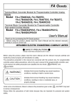
Timing chart of I/O signals
ON
i_bEN (Execution command)
OFF
o_bENO (Execution status)
OFF
Operating condition setting request
(Y signal)
OFF
ON
Operating condition setting completed
flag (X signal)
ON
ON
ON
OFF
ON
o_bOK (Normal completion)
OFF
o_bErr (Error completion)
OFF
o_uErrId (Error code)
Restrictions and precautions
4
0
• This FB does not include the error recovery processing. Prepare the error recovery processing separately to suit the user's
system and the expected operation.
• The FB cannot be used in an interrupt program.
• As this FB is executed, the A/D conversion processing stops, and thereafter when o_bOK (normal completion) turns on, the
conversion processing resumes.
• Putting an analog-digital converter module into operation requires the input range to be set according to the connected
devices and the system in use. Set up the module parameters of GX Works3 according to the application. For how to set up
the module parameters, refer to the user's manual (Application) of the analog-digital converter module used.
2 ANALOG-DIGITAL CONVERTER MODULE FB
2.1 M+R60AD(G)_RequestSetting
Error code
Error code
Description
Action
None
None
None
2
Labels to use
■Input labels
Name
Variable name
Data type
Scope
Description
Execution
command
i_bEN
Bit
On or off
On: The FB is activated.
Off: The FB is not activated.
Module label
i_stModule
Structure
The scope differs
depending on the
module label.
Specifies a module label of the analog-digital converter module.
■Output labels
Name
Variable name
Data type
Default value
Description
Execution status
o_bENO
Bit
Off
On: The execution command is on.
Off: The execution command is off.
Normal completion
o_bOK
Bit
Off
The on state indicates that the operation to enable each setting is
complete.
Error completion
o_bErr
Bit
Off
Always off
Error code
o_uErrId
Word [unsigned]
0
Always 0
2 ANALOG-DIGITAL CONVERTER MODULE FB
2.1 M+R60AD(G)_RequestSetting
5
2.2
M+R60AD(G)_OperateError
Name
■R60AD4, R60ADV8, R60ADI8
M+R60AD_OperateError
■R60AD8-G, R60AD16-G
M+R60ADG_OperateError
FB details
Item
Description
Functional overview
Monitors error codes and resets errors.
Symbol
M+R60AD_OperateError
Execution command
Module label
B
: i_bEN
DUT : i_stModule
Error reset request
B
: i_bErrReset
o_bENO :
B
Execution status
o_bOK :
B
Normal completion
o_bUnitErr :
UW
Module error code
o_uUnitAlarmCode :
UW
Module alarm code
o_bErr :
o_uErrId :
Relevant devices
Module error flag
B
o_uUnitErrCode :
Error completion
B
UW
Error code
Relevant modules
R60AD4, R60ADV8, R60ADI8, R60AD8-G, R60AD16-G
Relevant CPU modules
MELSEC iQ-R series CPU modules
Relevant engineering tool
GX Works3
Language to use
Ladder diagram
Number of basic steps
61 steps
The number of steps of the FB embedded in a program depends on the CPU model used and the input/output definitions.
Functional description
• As i_bEN (execution command) turns on, errors in the target module are monitored.
• After i_bEN (execution command) turns on, turning on i_bErrReset (error reset request) during an error allows the error to be
reset.
FB compilation method
Macro type
FB operation
Arbitrary execution type
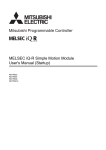
Timing chart of I/O signals
ON
i_bEN (Execution command)
OFF
o_bENO (Execution status)
OFF
i_bErrorReset (Error reset request)
OFF
Error clear request (Y signal)
OFF
Error flag (X signal)
OFF
o_bUnitErr (Module error flag)
OFF
ON
ON
ON
ON
ON
o_uUnitErrCode (Module error code)
0
Module error code
o_uUnitAlarmCode
(Module alarm code)
0
Module alarm code
0
0
ON
o_bOK (Normal completion)
OFF
o_bErr (Error completion)
OFF
o_uErrId (Error code)
6
2 ANALOG-DIGITAL CONVERTER MODULE FB
2.2 M+R60AD(G)_OperateError
0
Item
Description
Restrictions and precautions
• This FB does not include the error recovery processing. Prepare the error recovery processing separately to suit the user's
system and the expected operation.
• The FB cannot be used in an interrupt program.
• Putting an analog-digital converter module into operation requires the input range to be set according to the connected
devices and the system in use. Set up the module parameters of GX Works3 according to the application. For how to set up
the module parameters, refer to the user's manual (Application) of the analog-digital converter module used.
2
Error code
Error code
Description
Action
None
None
None
Labels to use
■Input labels
Name
Variable name
Data type
Scope
Description
Execution
command
i_bEN
Bit
On or off
On: The FB is activated.
Off: The FB is not activated.
Module label
i_stModule
Structure
The scope differs
depending on the
module label.
Specifies a module label of the analog-digital converter module.
Error reset request
i_bErrReset
Bit
On or off
Turn on this label to reset errors.
After completion of the error reset, turn off the label.
■Output labels
Name
Variable name
Data type
Default value
Description
Execution status
o_bENO
Bit
Off
On: The execution command is on.
Off: The execution command is off.
Normal completion
o_bOK
Bit
Off
The on state indicates that the error reset is complete.
Module error flag
o_bUnitErr
Bit
Off
The on state indicates that a module error has occurred.
Module error code
o_uUnitErrCode
Word [unsigned]
0
The error code of an error occurred is stored.
Module alarm code
o_uUnitAlarmCode
Word [unsigned]
0
The alarm code of an alarm occurred is stored.
Error completion
o_bErr
Bit
Off
Always off
Error code
o_uErrId
Word [unsigned]
0
Always 0
2 ANALOG-DIGITAL CONVERTER MODULE FB
2.2 M+R60AD(G)_OperateError
7
2.3
M+R60AD(G)_SetLoggingParam
Name
■R60AD4, R60ADV8, R60ADI8
M+R60AD_SetLoggingParam
■R60AD8-G, R60AD16-G
M+R60ADG_SetLoggingParam
FB details
Item
Description
Functional overview
Sets up the logging function of a specified channel.
Symbol
M+R60AD_SetLoggingParam
Execution command
Module label
Target CH
Logging enable/disable setting
DUT : i_stModule
UW
B
: i_uCH
: i_bLogEnable
UW
: i_uLogData
Logging cycle setting value
UW
: i_uLogCycleVal
Logging cycle unit setting
UW
: i_uLogCycleUnit
Post-trigger logging points
UW
: i_uLogPoints
Level trigger condition setting
UW
: i_uLogT rigCond
Trigger data
UW
: i_uLogT rigData
W
: i_wLogT rigValue
Module type
UW
o_bENO :
B
Execution status
o_bOK :
B
Normal completion
B
Error completion
o_bErr :
o_uErrId :
UW
Error code
: i_uUnitT ype
Relevant modules
R60AD4, R60ADV8, R60ADI8, R60AD8-G, R60AD16-G
Relevant CPU modules
MELSEC iQ-R series CPU modules
Relevant engineering tool
GX Works3
Language to use
Ladder diagram
Number of basic steps
437 steps
The number of steps of the FB embedded in a program depends on the CPU model used and the input/output definitions.
Functional description
8
: i_bEN
Logging data setting
Trigger setting value
Relevant devices
B
• Turning on i_bEN (execution command) allows the logging function of a specified channel to be set.
• This FB works for only one shot as i_bEN (execution command) turns on.
• The set values are enabled by turning on and off Operating condition setting request (Yn9) or executing the operating
condition setting request FB (M+R60AD(G)_RequestSetting).
• If the set value of the target channel is out of the range, o_bErr (error completion) turns on and the processing of the FB is
interrupted. In addition, the error code is stored in o_uErrId (error code). For the error code, refer to the list of error codes.
( Page 9 Error codes)
FB compilation method
Macro type
FB operation
Pulse execution type (single scan execution type)
2 ANALOG-DIGITAL CONVERTER MODULE FB
2.3 M+R60AD(G)_SetLoggingParam
Item
Description
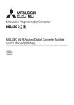
Timing chart of I/O signals
■When the operation is completed successfully
ON
i_bEN (Execution command) OFF
ON
o_bENO (Execution status)
Logging function parameter
setting write processing
OFF
Unexecuted
Write
2
Unexecuted
ON
o_bOK (Normal completion)
OFF
o_bErr (Error completion)
OFF
0
o_uErrId (Error code)
■When the operation is completed with an error
ON
i_bEN (Execution command) OFF
ON
o_bENO (Execution status)
OFF
Logging function parameter
setting write processing
Unexecuted
o_bOK (Normal completion)
OFF
o_bErr (Error completion)
OFF
ON
o_uErrId (Error code)
Restrictions and precautions
0
0
Error code
• This FB does not include the error recovery processing. Prepare the error recovery processing separately to suit the user's
system and the expected operation.
• The FB cannot be used in an interrupt program.
• Using the FB in a program that is to be executed only once, such as a subroutine program or a FOR-NEXT loop, has a
problem that i_bEN (execution command) can no longer be turned off and normal operation is not possible; Always use the
FB in a program that is capable of turning off the execution command.
• To use more than one of this FB, care must be taken to avoid duplication of the target channel.
• The FB requires the configuration of the ladder for every input label.
• If the parameters are set by means of the configuration function of GX Works3, this FB is not required.
• Putting an analog-digital converter module into operation requires the input range to be set according to the connected
devices and the system in use. Set up the module parameters of GX Works3 according to the application. For how to set up
the module parameters, refer to the user's manual (Application) of the analog-digital converter module used.
Error codes
Error code
Description
Action
100H
■R60AD4, R60ADV8, R60ADI8
The target channel is out of the setting
range.
Set the target channel within the following
range.
• R60AD4: 1 to 4
• R60ADV8/R60ADI8: 1 to 8
Review and correct the settings and then execute the FB again.
■R60AD8-G, R60AD16-G
The target channel is set out of the range.
Set the target channel within the following
range.
• R60AD8-G: 1 to 8
• R60AD16-G: 1 to 16
102H
■R60AD4, R60ADV8, R60ADI8
The module type is set out of the range.
Set the module type to the following values.
• R60AD4: 0
• R60ADV8: 1
• R60ADI8: 2
Review and correct the settings and then execute the FB again.
■R60AD8-G, R60AD16-G
The module type is set out of the range.
Set the module type to the following values.
• R60AD8-G: 0
• R60AD16-G: 1
2 ANALOG-DIGITAL CONVERTER MODULE FB
2.3 M+R60AD(G)_SetLoggingParam
9
Labels to use
■Input labels
Name
Variable name
Data type
Scope
Description
Execution
command
i_bEN
Bit
On or off
On: The FB is activated.
Off: The FB is not activated.
Module label
i_stModule
Structure
The scope differs depending on the
module label.
Specifies a module label of the analog-digital
converter module.
Target channel
i_uCH
Word [unsigned]
■R60AD4, R60ADV8, R60ADI8
R60AD4: 1 to 4
R60ADV8/R60ADI8: 1 to 8
Specifies a channel number.
■R60AD8-G, R60AD16-G
R60AD8-G: 1 to 8
R60AD16-G: 1 to 16
Logging enable/
disable setting
i_bLogEnable
Bit
On or off
On: Enables the logging function.
Off: Disables the logging function.
Logging data setting
i_uLogData
Word [unsigned]
0: Digital output value
1: Digital operation value
Sets the data to be logged.
Logging cycle
setting value
i_uLogCycleVal
Word [unsigned]
■R60AD4, R60ADV8, R60ADI8
When the logging cycle unit setting is
0: 80 to 32767
When the logging cycle unit setting is
1: 1 to 32767
When the logging cycle unit setting is
2: 1 to 3600
Sets the interval of cycles at which data is stored.
■R60AD8-G, R60AD16-G
When the logging cycle unit setting is
1: 10 to 32767
When the logging cycle unit setting is
2: 1 to 3600
Logging cycle unit
setting
i_uLogCycleUnit
Word [unsigned]
■R60AD4, R60ADV8, R60ADI8
0: s
1: ms
2: s
Specifies the unit of cycles at which data is
stored.
■R60AD8-G, R60AD16-G
1: ms
2: s
Post-trigger logging
points
i_uLogPoints
Word [unsigned]
■R60AD4, R60ADV8, R60ADI8
1 to 10000
Specifies the number of data to be logged after a
hold trigger occurs.
■R60AD8-G, R60AD16-G
1 to 1000
Level trigger
condition setting
i_uLogTrigCond
Word [unsigned]
0: Disable
1: Rise
2: Fall
3: Rise and fall
Sets the condition in which a level trigger is to be
used.
Set 0 if using no lever trigger.
Trigger data
i_uLogTrigData
Word [unsigned]
■R60AD4, R60ADV8, R60ADI8
0 to 4999
Specifies a buffer memory address to be
monitored by level trigger.
■R60AD8-G, R60AD16-G
0 to 11999
Trigger setting value
i_wLogTrigValue
Word [signed]
-32768 to 32767
Sets the level at which a level trigger is
generated.
Module type
i_uUnitType
Word [unsigned]
■R60AD4, R60ADV8, R60ADI8
0: R60AD4
1: R60ADV8
2: R60ADI8
Specifies a module type.
■R60AD8-G, R60AD16-G
0: R60AD8-G
1: R60AD16-G
10
2 ANALOG-DIGITAL CONVERTER MODULE FB
2.3 M+R60AD(G)_SetLoggingParam
■Output labels
Name
Variable name
Data type
Default value
Description
Execution status
o_bENO
Bit
Off
On: The execution command is on.
Off: The execution command is off.
Normal completion
o_bOK
Bit
Off
The on state indicates that the setting of the logging function
parameters is completed.
Error completion
o_bErr
Bit
Off
The on state indicates that an error has occurred in the FB.
Error code
o_uErrId
Word [unsigned]
0
The error code of an error occurred in the FB is stored.
2 ANALOG-DIGITAL CONVERTER MODULE FB
2.3 M+R60AD(G)_SetLoggingParam
2
11
2.4
M+R60AD(G)_SaveLogging
Name
■R60AD4, R60ADV8, R60ADI8
M+R60AD_SaveLogging
■R60AD8-G, R60AD16-G
M+R60ADG_SaveLogging
FB details
Item
Description
Functional overview
Saves the logging data of a specified channel into a file.
Symbol
M+R60AD_SaveLogging
Execution command
Module label
o_bENO :
Target CH
Maximum number of save files
UW
: i_uMaxNumber
B
: i_bOverWrite
UW
: i_uUnitT ype
B
Execution status
o_bOK :
B
Normal completion
o_bMakingFile :
B
Creating a file
o_bExceedNumber :
B
Maximum number exceeded flag
o_bErr :
B
Error completion
DUT : i_stModule
: i_uCH
Module type
12
: i_bEN
UW
Overwrite save command
Relevant devices
B
o_uErrId :
UW
Error code
Relevant modules
R60AD4, R60ADV8, R60ADI8, R60AD8-G, R60AD16-G
Relevant CPU modules
MELSEC iQ-R series CPU modules
Relevant engineering tool
GX Works3
Language to use
Ladder diagram
Number of basic steps
2309 steps
The number of steps of the FB embedded in a program depends on the CPU model used and the input/output definitions.
2 ANALOG-DIGITAL CONVERTER MODULE FB
2.4 M+R60AD(G)_SaveLogging
Item
Functional description
Description
• As i_bEN (execution command) turns on and the logging hold flag turns on, the FB sorts the logging data, the number of which is
equal to the number of logging points, in a chronological order from the head pointer, and saves the data along with the trigger
generation information in the SD memory card, inserted into the CPU module, in a CSV format.
• Provided that i_bEN (execution command) is on, this FB starts the save processing of logging data every time the logging hold
flag turns on.
• It takes multiple scans to complete the save processing of logging data. Check o_bOK (normal completion) to see that the
processing is complete.
• When this FB saves data in an SD memory card, the file name is given as follows: "AD" + "Middle two digits of the four digits
representing the start I/O number of the analog-digital converter module" + "Target channel" + "Consecutive number" + ".CSV".
The maximum number of consecutive number varies with i_uMaxNumber (maximum number of save files). Turning off i_bEN
(execution command) results in the consecutive number being reset, and thereafter a consecutive number is given from 1 again.
Suppose that the I/O number of the analog-digital converter module is H0450, the target channel is 3, i_uMaxNumber (maximum
number of save files) is 30, and the number of file creation by this FB is 6th. For the R60AD4, R60ADV8, and R60ADI8, the file
name is "AD453006.CSV"; for the R60AD8-G and R60AD16-G, "AD4503006.CSV".
• When this FB creates a CSV file in an SD memory card, a file of the same name, if already exists in the SD memory card, is
replaced with the newly created file.
• If i_bOverWrite (overwrite save command) is on and the number of files that this FB has saved in an SD memory card exceeds
i_uMaxNumber (maximum number of save files), the consecutive number returns back to 1 and the save processing of logging
data continues.
• If i_bOverWrite (overwrite save command) is off and the number of files that this FB has saved in an SD memory card reaches
i_uMaxNumber (maximum number of save files), the save processing of logging data stops.
• If the number of files that this FB has saved in an SD memory card reaches i_uMaxNumber (maximum number of save files),
o_bExceedNumber (maximum number reach flag) turns on regardless of the on or off state of i_bOverWrite (overwrite save
command).
• If an incorrect value is set in i_uCH (target channel) or i_uMaxNumber (maximum number of save files), o_bErr (error completion)
turns on and the processing of the FB is interrupted. In addition, the error code is stored in o_uErrId (error code).
• A CPU error occurs in the following cases: when this FB has been executed with no SD memory card inserted into the CPU
module; when the inserted SD memory card has no sufficient free space; or when the number of files stored exceeds the limit. In
the event of an error, if the CPU module is in a stop error state, o_bErr (error completion) and o_uErrId (error code) are not
updated. In the event of an error, if the CPU module is in a continuation error state, o_bErr (error completion) turns on and the
error code is stored in o_uErrId (error code). For the capacity of SD memory cards and the number of files stored, refer to the
MELSEC iQ-R Module Configuration Manual. The operating status (continue or stop) of the CPU module at the time of the failure
of access to the SD memory card can be set with the parameter.
• For the format of CSV files that this FB creates, refer to CSV File Output Format of the FB for Saving Logging Data ( Page 34
CSV File Output Format of the FB for Saving Logging Data). The specified module type is reflected in the file version of the CSV
file.
FB compilation method
Macro type
FB operation
Pulse execution type (multiple scan execution type)
2 ANALOG-DIGITAL CONVERTER MODULE FB
2.4 M+R60AD(G)_SaveLogging
2
13
Item
Description
Timing chart of I/O
signals
■When the operation is completed successfully
ON
i_bEN (Execution command)
OFF
o_bENO (Execution status)
OFF
Logging hold flag
OFF
o_bMakingFile (Creating a file)
OFF
o_bOK (Normal completion)
OFF
o_bExceedNumber
(Maximum number exceeded flag)
OFF
o_bErr (Error completion)
OFF
ON
ON
ON
ON
ON
0
o_uErrId (Error code)
■When the operation is completed with an error
ON
i_bEN (Execution command)
OFF
o_bENO (Execution status)
OFF
Logging hold flag
OFF
o_bMakingFile (Creating a file)
OFF
o_bOK (Normal completion)
OFF
o_bExceedNumber
(Maximum number exceeded flag)
OFF
o_bErr (Error completion)
OFF
ON
ON
ON
ON
o_uErrId (Error code)
Restrictions and
precautions
14
0
Error code
0
• This FB does not include the error recovery processing. Prepare the error recovery processing separately to suit the user's
system and the expected operation.
• The FB cannot be used in an interrupt program.
• Using the FB in a program that is to be executed only once, such as a subroutine program or a FOR-NEXT loop, has a problem
that i_bEN (execution command) can no longer be turned off and normal operation is not possible; Always use the FB in a
program that is capable of turning off the execution command.
• This FB cannot save logging data in a medium other than an SD memory card.
• This FB makes use of the SP.FWRITE instruction, and thus if an error occurs in the execution of the SP.FWRITE instruction, a
CPU error occurs.
• To use more than one of this FB, create an interlock to avoid simultaneous execution. When saving logging data of channel 1 and
channel 2, first check that o_bOK (normal completion) of the FB on channel 1 is on, and turn on i_bEN (execution command) of
the FB on channel 2.
• If SM606 (SD memory card forced disable instruction) is on at the time of saving logging data, the SP.FWRITE instruction is not
processed, resulting in the logging data not being saved. In this case, o_bErr (error completion) turns on and the error code is
stored in o_uErrId (error code).
• The FB requires the configuration of the ladder for every input label.
• Set i_uMaxNumber (maximum number of save files) with consideration for the capacity of the SD memory card and the number
of files stored. If the capacity of the SD memory card or the number of files stored is exceeded as a result of execution of this FB,
a CPU error occurs. For the capacity of SD memory cards and the number of files stored, refer to the MELSEC iQ-R Module
Configuration Manual.
• Putting an analog-digital converter module into operation requires the input range to be set according to the connected devices
and the system in use. Set up the module parameters of GX Works3 according to the application. For how to set up the module
parameters, refer to the user's manual (Application) of the analog-digital converter module used.
2 ANALOG-DIGITAL CONVERTER MODULE FB
2.4 M+R60AD(G)_SaveLogging
Error code
Error code
Description
Action
100H
■R60AD4, R60ADV8, R60ADI8
The target channel is set out of the range.
Set the target channel within the following
range.
R60AD4: 1 to 4
R60ADV8/R60ADI8: 1 to 8
Review and correct the settings and then execute the FB again.
2
■R60AD8-G, R60AD16-G
The target channel is set out of the range.
Set the target channel within the following
range.
R60AD8-G: 1 to 8
R60AD16-G: 1 to 16
101H
The maximum number of save files is set
out of the range.
The maximum number of save files is set
out of the range of 1 to 999.
Review and correct the settings and then execute the FB again.
102H
■R60AD4, R60ADV8, R60ADI8
The module type is set out of the range.
Set the module type to the following values.
• R60AD4: 0
• R60ADV8: 1
• R60ADI8: 2
Review and correct the settings and then execute the FB again.
■R60AD8-G, R60AD16-G
The module type is set out of the range.
Set the module type to the following values.
• R60AD8-G: 0
• R60AD16-G: 1
200H
The processing is interrupted because the
logging hold flag turns off while logging
data is being saved.
The partially created CSV file is saved in
the SD memory card.
201H
An access to the SD memory card has
failed because SM606 (SD memory card
forced disable instruction) is turned on.
While logging data is being saved, turning
on SM606 (SD memory card forced disable
instruction) results in the partially created
CSV file being saved in the SD memory
card.
Turn off SM606 and check that SM607 (SD memory card forced
stop status flag) is turned off, then execute the FB again.
202H
Execution of this FB has been attempted
without inserting an SD memory card into
the CPU module.
Insert an SD memory card for saving the target CSV files into the
CPU module, and then execute the FB again.
203H
An access to the SD memory card has
failed because SM600 (Memory card
available flag) is off (unavailable).
Make the SD memory card an available state, and then execute
the FB again.
204H
The SD memory card is frequently
accessed from programs in addition to this
FB, and a timeout has occurred in the
logging data write processing.
Reduce the frequency of the access to the SD memory card.
205H
Because SM601 (Memory card protect
flag) is on (write inhibited), data cannot be
written to the SD memory card.
Turn off (write enabled) the protect switch on the SD memory card,
check that SM601 is off, and execute the FB again.
Error codes other than the above
Error codes related to the SP.FWRITE
instruction executed when logging data is
written to an SD memory card
For details on the error code that has occurred, refer to the
description of the SP.FWRITE instruction. ( MELSEC iQ-R
Programming Manual (Instructions, Standard Functions/Function
Blocks))
2 ANALOG-DIGITAL CONVERTER MODULE FB
2.4 M+R60AD(G)_SaveLogging
15
Labels to use
■Input labels
Name
Variable name
Data type
Scope
Description
Execution
command
i_bEN
Bit
On or off
On: The FB is activated.
Off: The FB is not activated.
Module label
i_stModule
Structure
The scope differs depending on
the module label.
Specifies a module label of the analog-digital
converter module.
Target channel
i_uCH
Word [unsigned]
■R60AD4, R60ADV8, R60ADI8
R60AD4: 1 to 4
R60ADV8/R60ADI8: 1 to 8
Specifies a channel number.
■R60AD8-G, R60AD16-G
R60AD8-G: 1 to 8
R60AD16-G: 1 to 16
Maximum number
of save files
i_uMaxNumber
Word [unsigned]
1 to 999
Specifies the maximum number of CSV files that this
FB saves.
Overwrite save
command
i_bOverWrite
Bit
On or off
Specify whether or not to overwrite the CSV files
having smaller consecutive numbers when the
number of CSV files that this FB has saved reaches
the maximum number of save files.
If the setting is off, the save processing of logging data
stops.
Module type
i_uUnitType
Word [unsigned]
■R60AD4, R60ADV8, R60ADI8
0: R60AD4
1: R60ADV8
2: R60ADI8
Specifies a module type that is to be written to the file
version of the CSV file that this FB saves.
■R60AD8-G, R60AD16-G
0: R60AD8-G
1: R60AD16-G
■Output labels
16
Name
Variable name
Data type
Default value
Description
Execution status
o_bENO
Bit
Off
On: The execution command is on.
Off: The execution command is off.
Normal completion
o_bOK
Bit
Off
The on state indicates that the file save is complete.
This label turns off as logging resumes.
Creating file
o_bMakingFile
Bit
Off
The on state indicates that files are being created.
Maximum number
reach flag
o_bExceedNumber
Bit
Off
The on state indicates that the number of CSV files that this FB
has saved has reached the maximum number of save files.
Error completion
o_bErr
Bit
Off
The on state indicates that an error has occurred in the FB.
Error code
o_uErrId
Word [unsigned]
0
The error code of an error occurred in the FB is stored.
2 ANALOG-DIGITAL CONVERTER MODULE FB
2.4 M+R60AD(G)_SaveLogging
3
DIGITAL-ANALOG CONVERTER MODULE FB
3.1
M+R60DA(G)(16)_RequestSetting
Name
■R60DA4, R60DAV8, R60DAI8
3
M+R60DA_RequestSetting
■R60DA8-G
M+R60DAG_RequestSetting
■R60DA16-G
M+R60DAG16_RequestSetting
FB details
Item
Description
Functional overview
Enables the settings of each function.
Symbol
M+R60DA_RequestSetting
Execution command
Module label
B
: i_bEN
DUT : i_stModule
o_bENO :
B
Execution status
o_bOK :
B
Normal completion
o_bErr :
B
Error completion
o_uErrId :
Relevant devices
UW
Error code
Relevant modules
R60DA4, R60DAV8, R60DAI8, R60DA8-G, R60DA16-G
Relevant CPU modules
MELSEC iQ-R series CPU modules
Relevant engineering tool
GX Works3
Language to use
Ladder diagram
Number of basic steps
24 steps
The number of steps of the FB embedded in a program depends on the CPU model used and the input/output definitions.
Functional description
• Turning on i_bEN (execution command) allows the settings of all channels to be enabled. For what settings are enabled,
refer to the user's manual (Application) of the digital-analog converter module used.
• This FB continues its execution until the completion of the settings of each function after i_bEN (execution command) turns
on.
FB compilation method
Macro type
FB operation
Pulse execution type (multiple scan execution type)
Timing chart of I/O signals
ON
i_bEN (Execution command) OFF
ON
o_bENO (Execution status)
OFF
Operating condition setting
request (Y signal)
OFF
Operating condition setting
completed flag (X signal)
ON
ON
ON
OFF
ON
o_bOK (Normal completion)
OFF
o_bErr (Error completion)
OFF
o_uErrId (Error code)
0
3 DIGITAL-ANALOG CONVERTER MODULE FB
3.1 M+R60DA(G)(16)_RequestSetting
17
Item
Description
Restrictions and precautions
• This FB does not include the error recovery processing. Prepare the error recovery processing separately to suit the user's
system and the expected operation.
• The FB cannot be used in an interrupt program.
• This FB turns on or off Operating condition setting request (Yn9). While this FB is in execution, be careful that the D/A
conversion stops.
• Putting a digital-analog converter module into operation requires the output range and operation mode to be set according to
the connected devices and the system in use. Set up the module parameters of GX Works3 according to the application. For
how to set up the module parameters, refer to the user's manual of the digital-analog converter module (Application).
Error code
Error code
Description
Action
None
None
None
Labels to use
■Input labels
Name
Variable name
Data type
Scope
Description
Execution
command
i_bEN
Bit
On or off
On: The FB is activated.
Off: The FB is not activated.
Module label
i_stModule
Structure
The scope differs
depending on the
module label.
Specifies a module label of the digital-analog converter module.
■Output labels
18
Name
Variable name
Data type
Default value
Description
Execution status
o_bENO
Bit
Off
On: The execution command is on.
Off: The execution command is off.
Normal completion
o_bOK
Bit
Off
The on state indicates that the operation to enable each setting is
complete.
Error completion
o_bErr
Bit
Off
Always off
Error code
o_uErrId
Word [unsigned]
0
Always 0
3 DIGITAL-ANALOG CONVERTER MODULE FB
3.1 M+R60DA(G)(16)_RequestSetting
3.2
M+R60DA(G)(16)_OperateError
Name
■R60DA4, R60DAV8, R60DAI8
M+R60DA_OperateError
■R60DA8-G
3
M+R60DAG_OperateError
■R60DA16-G
M+R60DAG16_OperateError
FB details
Item
Description
Functional overview
Monitors error codes and resets errors.
Symbol
M+R60DA_OperateError
o_bENO :
B
Execution status
DUT : i_stModule
o_bOK :
B
Normal completion
: i_bErrReset
o_bUnitErr :
B
Module error flag
Execution command
Module label
B
Error reset request
B
: i_bEN
o_uUnitErrCode :
o_bErr :
o_uErrId :
Relevant devices
UW
B
UW
Module error code
Error completion
Error code
Relevant modules
R60DA4, R60DAV8, R60DAI8, R60DA8-G, R60DA16-G
Relevant CPU modules
MELSEC iQ-R series CPU modules
Relevant engineering tool
GX Works3
Language to use
Ladder diagram
Number of basic steps
45 steps
The number of steps of the FB embedded in a program depends on the CPU model used and the input/output definitions.
Functional description
• As i_bEN (execution command) turns on, the error information in the target module is monitored.
• After i_bEN (execution command) turns on, turning on i_bErrReset (error reset request) during an error allows the error to be
reset.
FB compilation method
Macro type
FB operation
Arbitrary execution type
Timing chart of I/O signals
ON
i_bEN (Execution command) OFF
ON
o_bENO (Execution status)
OFF
i_bErrorReset
(Error reset request)
OFF
ON
ON
Error clear request (Y signal) OFF
ON
Error flag (X signal)
OFF
o_bUnitErr
(Module error flag)
OFF
ON
o_uUnitErrCode
(Module error code)
0
Module error code
0
ON
o_bOK (Normal completion)
OFF
o_bErr (Error completion)
OFF
o_uErrId (Error code)
0
3 DIGITAL-ANALOG CONVERTER MODULE FB
3.2 M+R60DA(G)(16)_OperateError
19
Item
Description
Restrictions and precautions
• This FB does not include the error recovery processing. Prepare the error recovery processing separately to suit the user's
system and the expected operation.
• The FB cannot be used in an interrupt program.
• Putting a digital-analog converter module into operation requires the output range and operation mode to be set according to
the connected devices and the system in use. Set up the module parameters of GX Works3 according to the application. For
how to set up the module parameters, refer to the user's manual of the digital-analog converter module (Application).
Error code
Error code
Description
Action
None
None
None
Labels to use
■Input labels
Name
Variable name
Data type
Scope
Description
Execution
command
i_bEN
Bit
On or off
On: The FB is activated.
Off: The FB is not activated.
Module label
i_stModule
Structure
The scope differs
depending on the
module label.
Specifies a module label of the digital-analog converter module.
Error reset request
i_bErrReset
Bit
On or off
Turn on this label to reset the errors.
Turn off this label after the error reset.
■Output labels
20
Name
Variable name
Data type
Default value
Description
Execution status
o_bENO
Bit
Off
On: The execution command is on. (Module errors are being
monitored.)
Off: The execution command is off.
Normal completion
o_bOK
Bit
Off
The on state indicates that executing the error reset instruction has
been completed.
Module error flag
o_bUnitErr
Bit
Off
The on state indicates that a module error has occurred.
Module error code
o_uUnitErrCode
Word [unsigned]
0
The error code of an error occurred is stored.
Error completion
o_bErr
Bit
Off
Always off
Error code
o_uErrId
Word [unsigned]
0
Always 0
3 DIGITAL-ANALOG CONVERTER MODULE FB
3.2 M+R60DA(G)(16)_OperateError
3.3
M+R60DA_WaveOutputSetting
Name
M+R60DA_WaveOutputSetting
FB details
3
Item
Description
Functional overview
Sets the waveform output of a specified channel or all channels.
Symbol
M+R60DA_WaveOutputSetting
Execution command
Module label
: i_bEN
DUT : i_stModule
Target CH
UW
: i_uCH
Output setting during wave output stop
UW
: i_uOutputSelect
Output value during wave output stop
W
: i_wOutputValue
Wave pattern start address setting
UD
: i_udStartingAddr
Wave pattern data points setting
UD
: i_udPointsSetting
W
: i_wFrequency
Constant for wave output conversion cycle
UW
: i_uConvSpeed
Module type
UW
: i_uUnitT ype
Wave pattern output repetition setting
Relevant devices
B
o_bENO :
B
Execution status
o_bOK :
B
Normal completion
B
Error completion
o_bErr :
o_uErrId :
Relevant modules
R60DA4, R60DAV8, R60DAI8
Relevant CPU modules
MELSEC iQ-R series CPU modules
Relevant engineering tool
GX Works3
UW
Error code
Language to use
Ladder diagram
Number of basic steps
862 steps
The number of steps of the FB embedded in a program depends on the CPU model used and the input/output definitions.
Functional description
• As i_bEN (execution command) turns on, the waveform output settings of a specified channel or all channels are written.
• The waveform output setting is enabled only when the output mode setting is set to the waveform output mode. The waveform
data for analog output is required to be set in advance.
• The set values are enabled by turning on and off Operating condition setting request (Yn9) or executing the operating condition
setting request FB (M+R60DA_RequestSetting).
• If the set value of the target channel is out of the range, o_bErr (error completion) turns on and the processing of the FB is
interrupted. In addition, the error code is stored in o_uErrId (error code). For the error code, refer to the list of error codes. (
Page 22 Error code)
FB compilation method
Macro type
FB operation
Pulse execution type (single scan execution type)
3 DIGITAL-ANALOG CONVERTER MODULE FB
3.3 M+R60DA_WaveOutputSetting
21
Item
Description
Timing chart of I/O
signals
■When the operation is completed successfully
ON
i_bEN (Execution command) OFF
ON
o_bENO (Execution status)
OFF
Each setting value write
processing
Unexecuted
Write
Unexecuted
ON
o_bOK (Normal completion)
OFF
o_bErr (Error completion)
OFF
0
o_uErrId (Error code)
■When the operation is completed with an error
ON
i_bEN (Execution command) OFF
ON
o_bENO (Execution status)
OFF
Each setting value write
processing
Unexecuted
o_bOK (Normal completion)
OFF
o_bErr (Error completion)
OFF
ON
o_uErrId (Error code)
Restrictions and
precautions
0
Error code
0
• This FB does not include the error recovery processing. Prepare the error recovery processing separately to suit the user's
system and the expected operation.
• The FB cannot be used in an interrupt program.
• Using the FB in a program that is to be executed only once, such as a subroutine program or a FOR-NEXT loop, has a problem
that i_bEN (execution command) can no longer be turned off and normal operation is not possible; Always use the FB in a
program that is capable of turning off the execution command.
• To use more than one of this FB, care must be taken to avoid duplication of the target channel.
• The FB requires the configuration of the ladder for every input label.
• Putting the R60DA4, R60DAV8, or R60DAI8 into operation requires the output range to be set according to the connected
devices and the system in use. Set up the module parameters of GX Works3 according to the application. For how to set up the
module parameters, refer to the MELSEC iQ-R Digital-Analog Converter Module User's Manual (Application).
Error code
22
Error code
Description
Action
100H
The target channel is set out of the range.
Set the target channel within the following
range.
• R60DA4: 1 to 4, 15
• R60DAV8/R60DAI8: 1 to 8, 15
Review and correct the settings and then execute the FB again.
102H
The module type is set out of the range.
Set the module type to the following values.
• R60DA4: 0
• R60DAV8: 1
• R60DAI8: 2
Review and correct the settings and then execute the FB again.
3 DIGITAL-ANALOG CONVERTER MODULE FB
3.3 M+R60DA_WaveOutputSetting
Labels to use
■Input labels
Name
Variable name
Data type
Scope
Description
Execution
command
i_bEN
Bit
On or off
On: The FB is activated.
Off: The FB is not activated.
Module label
i_stModule
Structure
The scope differs depending on the
module label.
Specifies a module label of the digital-analog
converter module.
Target channel
i_uCH
Word [unsigned]
For the R60DA4
• 1 to 4, 15
For the R60DAV8 and R60DAI8
• 1 to 8, 15
For the R60DA4
• 1 to 4: The corresponding channel number
is specified.
• 15: All channels are specified.
For the R60DAV8 and R60DAI8
• 1 to 8: The corresponding channel number
is specified.
• 15: All channels are specified.
Output selection
during waveform
output stop
i_uOutputSelect
Word [unsigned]
0: 0V/0mA
1: Offset value
2: Output setting value during waveform
output stop
Specifies the output value during waveform
output stop.
Output setting value
during waveform
output stop
i_wOutputValue
Word [signed]
For a range of 0 to 5V, 1 to 5V, 0 to 20mA,
or 4 to 20mA
• 0 to 32767
For a range of -10 to 10V
• -32768 to 32767
Sets the value to be output when 2 (Output
setting value during waveform output stop) is
selected in the output selection during
waveform output stop.
Waveform pattern
start address setting
i_udStartingAddr
Double Word
[unsigned]
10000 to 89999
Sets the start address of a waveform pattern
to be output.
Number of
waveform pattern
points setting
i_udPointsSetting
Double Word
[unsigned]
1 to 80000 (point)
Sets the number of data points of a
waveform pattern to be output.
Number of
waveform outputs
setting
i_wFrequency
Word [signed]
-1: Infinite repetition output
1 to 32767: Specified number of times
output
Sets the number of output times of a
waveform pattern.
Waveform output
conversion cycle
constant
i_uConvSpeed
Word [unsigned]
1 to 5000
Sets the constant that defines the
conversion cycle of waveform output.
Module type
i_uUnitType
Word [unsigned]
0: R60DA4
1: R60DAV8
2: R60DAI8
Specifies a module type.
3
■Output labels
Name
Variable name
Data type
Default value
Description
Execution status
o_bENO
Bit
Off
On: The execution command is on.
Off: The execution command is off.
Normal completion
o_bOK
Bit
Off
The on state indicates that setting the waveform output has been
completed.
Error completion
o_bErr
Bit
Off
The on state indicates that an error has occurred in the FB.
Error code
o_uErrId
Word [unsigned]
0
The error code of an error occurred in the FB is stored.
3 DIGITAL-ANALOG CONVERTER MODULE FB
3.3 M+R60DA_WaveOutputSetting
23
3.4
M+R60DA_WaveDataStoreCsv
Name
M+R60DA_WaveDataStoreCsv
FB details
Item
Description
Functional overview
Reads out data from the CSV file that holds the parameters and the waveform data (number of waveform data points and
waveform data) of the waveform output function, and writes the data to the buffer memory of the digital-analog converter
module.
Symbol
M+R60DA_WaveDateStoreCsv
Execution command
Module label
B
DUT : i_stModule
Relevant devices
B
Execution status
o_bOK :
B
Normal completion
B
Error completion
S
: i_sFileName
o_bErr :
: i_uUnitT ype
o_uErrId :
Relevant modules
R60DA4, R60DAV8, R60DAI8
Relevant CPU modules
MELSEC iQ-R series CPU modules
Relevant engineering tool
GX Works3
UW
Error code
Language to use
Ladder diagram
Number of basic steps
660 steps
The number of steps of the FB embedded in a program depends on the CPU model used and the input/output definitions.
Functional description
24
o_bENO :
UW
CSV file name
Module type
: i_bEN
• As i_bEN (execution command) turns on, the FB reads out the parameters and waveform data of the waveform output
function from the CSV file, which is stored in the SD memory card inserted in the CPU module, and stores the data to the
buffer memory of the digital-analog converter module. For the waveform output function, refer to the MELSEC iQ-R DigitalAnalog Converter Module User's Manual (Application).
• For the parameters and data of the waveform output function and the buffer memory address of storage destination, which
are related to this FB, refer to Storage Source "Parameter/Data of Waveform Output Function" and Storage Destination
Buffer Memory ( Page 36 Storage Source "Parameter/Data of Waveform Output Function" and Storage Destination
Buffer Memory). At first, the FB reads all the parameters of the waveform output function from the CSV file, and stores them
in the buffer memory. Next, the FB reads the waveform data, the number of which is specified by the number of waveform
data points in the row 100 in the CSV file, in the order starting from the row 101, and stores the data in the order from the
start address (Un\G10000) of the waveform data registration area in the buffer memory. The CSV file has the settings for
eight channels. The number of channels to be used depends on the module type. Note that the waveform output data
creation tool of GX Works3 makes is easy to create the CSV file of the waveform output function.
• If this FB is executed with no SD memory card inserted into the CPU module, o_bErr (error completion) turns on and the
processing of the FB is interrupted. In addition, the error code 202H is stored in o_uErrId (error code). For the error code,
refer to the list of error codes. ( Page 26 Error code)
• If this FB is executed with the special relay SM606 (SD memory card forced disable instruction) turning on, o_bErr (error
completion) turns on and the processing of the FB is interrupted. In addition, the error code 201H is stored in o_uErrId (error
code). For the error code, refer to the list of error codes. ( Page 26 Error code)
• If a CSV file specified by i_sFileName (CSV file name) does not exist in the SD memory card inserted into the CPU module,
a CPU error (error code: 8002H) occurs.
• A setting that the CPU module enters a stop error state during a CPU error does not allow o_bErr (error completion) and
o_uErrId (error code) to be updated. The operating status (continue/stop) of the CPU module that results from a CPU error
can be set in [RAS Setting]. ("File Name Specification Incorrect" in "CPU Module Operation Setting at Error Detected" from
[CPU Parameter] - [RAS Setting])
• Before processing of the FB is complete, turning off i_bEN (execution command) results in the processing being interrupted.
In this case, the data that is already stored in the buffer memory is not cleared. Executing the FB once again allows read
processing to start from the beginning.
• Do not remove the SD memory card while this FB is being executed. For how to insert and remove an SD memory card,
refer to the MELSEC iQ-R CPU Module User's Manual (Startup).
FB compilation method
Macro type
FB operation
Pulse execution type (multiple scan execution type)
3 DIGITAL-ANALOG CONVERTER MODULE FB
3.4 M+R60DA_WaveDataStoreCsv
Item
Description
Timing chart of I/O signals
■When the operation is completed successfully
ON
i_bEN (Execution command) OFF
ON
o_bENO (Execution status)
OFF
Reading a CSV file
in the SD memory card
Unexecuted
Buffer memory update
processing
Update stopped
Executing SP.FREAD
Unexecuted
Update in progress
Update stopped
3
ON
o_bOK (Normal completion)
OFF
o_bErr (Error completion)
OFF
o_uErrId (Error code)
0
■When the operation is completed with an error
ON
i_bEN (Execution command) OFF
ON
o_bENO (Execution status)
OFF
Reading a CSV file
in the SD memory card
Unexecuted
Buffer memory update
processing
Update stopped
o_bOK (Normal completion)
OFF
o_bErr (Error completion)
OFF
ON
o_uErrId (Error code)
Restrictions and precautions
0
Error code
0
• This FB takes some time to complete the processing because a large number of scans is necessary until the completion of
the processing. Thus, the recommended use is to execute the FB during a warm-up of the R60DA4, R60DAV8, or R60DAI8.
• This FB does not include the error recovery processing. Prepare the error recovery processing separately to suit the user's
system and the expected operation.
• The FB cannot be used in an interrupt program.
• Using the FB in a program that is to be executed only once, such as a subroutine program or a FOR-NEXT loop, has a
problem that i_bEN (execution command) can no longer be turned off and normal operation is not possible; Always use the
FB in a program that is capable of turning off the execution command.
• This FB makes use of the SP.FREAD instruction, and so an error in the execution of the SP.FREAD instruction causes a
CPU error.
• When processing that accesses the SD memory card, such as the data logging function of the CPU module, is executed
together with this FB, the time to complete the execution of the FB may be extended or the error 204H (timeout) may occur.
• If more than one of this FB is used, simultaneous execution is not possible.
• The FB requires the configuration of the ladder for every input label.
• Putting the R60DA4, R60DAV8, or R60DAI8 into operation requires the output range to be set according to the connected
devices and the system in use. Set up the module parameters of GX Works3 according to the application. For how to set up
the module parameters, refer to the MELSEC iQ-R Digital-Analog Converter Module User's Manual (Application).
3 DIGITAL-ANALOG CONVERTER MODULE FB
3.4 M+R60DA_WaveDataStoreCsv
25
Error code
Error code
Description
Action
102H
The module type is set out of the range.
Set the module type to the following values.
• R60DA4: 0
• R60DAV8: 1
• R60DAI8: 2
Review and correct the settings and then execute the FB again.
201H
An access to the SD memory card has
failed because SM606 (SD memory card
forced disable instruction) is turned on.
Turn off SM606 and check that SM607 (SD memory card forced
stop status flag) is turned off, then execute the FB again.
202H
Execution of this FB has been attempted
without inserting an SD memory card into
the CPU module.
Insert an SD memory card that has the target CSV files into the
CPU module, and execute the FB again.
Insert a usable SD memory card in the CPU module, and save the
target CSV file with the PLC user data write function of GX
Works3. Then, execute the FB again.
203H
An access to the SD memory card has
failed because SM605 (Memory card
insertion/removal inhibit flag) is off (removal
allowed).
Turn on (removal inhibited) SM605 (Memory card insertion/
removal inhibit flag), and execute the FB again.
204H
The SD memory card is frequently
accessed from programs in addition to this
FB, and a timeout has occurred in the
waveform data reading processing.
Reduce the frequency of the access to the SD memory card.
Error codes other than the above
Error codes related to the SP.FREAD
instruction executed when the parameter
and waveform data of the waveform output
function are read from the SD memory card
For details on the error code that has occurred, refer to the
description of the SP.FREAD instruction. ( MELSEC iQ-R
Programming Manual (Instructions, Standard Functions/Function
Blocks))
Labels to use
■Input labels
Name
Variable name
Data type
Scope
Description
Execution
command
i_bEN
Bit
On or off
On: The FB is activated.
Off: The FB is not activated.
Module label
i_stModule
Structure
The scope differs
depending on the
module label.
Specifies a module label of the digital-analog converter module.
CSV file name
i_sFileName
Character string
[unicode]
Within 64
characters
Specifies a name of the CSV file in which the parameters and
waveform data of the waveform output function are stored.
Only the file attribute CSV is valid.
For details on the CSV file format, refer to the following:
Page 38 CSV File Format of the FB for Reading Wave Data
(CSV File)
Module type
i_uUnitType
Word [unsigned]
0: R60DA4
1: R60DAV8
2: R60DAI8
Specifies a module type.
■Output labels
26
Name
Variable name
Data type
Default value
Description
Execution status
o_bENO
Bit
Off
On: The execution command is on.
Off: The execution command is off.
Normal completion
o_bOK
Bit
Off
The on state indicates that writing the parameters and waveform
data of the waveform output function in the CSV file to the buffer
memory of the digital-analog converter module is complete.
Error completion
o_bErr
Bit
Off
The on state indicates that an error has occurred in the FB.
Error code
o_uErrId
Word [unsigned]
0
The error code of an error occurred in the FB is stored.
3 DIGITAL-ANALOG CONVERTER MODULE FB
3.4 M+R60DA_WaveDataStoreCsv
3.5
M+R60DA_WaveDataStoreDev
Name
M+R60DA_WaveDataStoreDev
FB details
3
Item
Description
Functional overview
Reads out data from the file register (ZR) that holds the parameters and the waveform data (number of waveform data points
and waveform data) of the waveform output function, and writes the data to the buffer memory of the digital-analog converter
module.
Symbol
M+R60DA_WaveDateStoreDev
Execution command
Module label
Relevant devices
B
: i_bEN
DUT : i_stModule
Read start address
UD
: i_udReadDataAddr
Module type
UW
: i_uUnitT ype
o_bENO :
B
Execution status
o_bOK :
B
Normal completion
B
Error completion
o_bErr :
o_uErrId :
Relevant modules
R60DA4, R60DAV8, R60DAI8
Relevant CPU modules
MELSEC iQ-R series CPU modules
Relevant engineering tool
GX Works3
UW
Error code
Language to use
Ladder diagram
Number of basic steps
668 steps
The number of steps of the FB embedded in a program depends on the CPU model used and the input/output definitions.
Functional description
• As i_bEN (execution command) turns on, the FB reads the parameters and waveform data of the waveform output function
from the file register in the serial number access method (ZR), and stores them in the buffer memory of the digital-analog
converter module. For the waveform output function, refer to the MELSEC iQ-R Digital-Analog Converter Module User's
Manual (Application).
• For the parameters and data of the waveform output function and the buffer memory address of storage destination, which
are related to this FB, refer to Storage Source "Parameter/Data of Waveform Output Function" and Storage Destination
Buffer Memory ( Page 36 Storage Source "Parameter/Data of Waveform Output Function" and Storage Destination
Buffer Memory).
• This FB reads the parameters of the waveform output function from ZR (m+0) specified by i_udReadDataAddr (read start
address), and stores them in the buffer memory. Next, the FB reads the waveform data, the number of which is specified by
the number of waveform data points in ZR (m+98, 99), in the order starting from ZR (m+100), and stores the data in the order
from the start address (Un\G10000) of the waveform data registration area in the buffer memory. Note that the waveform
output data creation tool of GX Works3 makes it easy to create the data of the file register (ZR) of the wave output function.
The character m is the read start address of the file register (ZR). Specifying the number of points to be used in [File Setting]
allows the reservation of file registers for any desired number and the distribution of data at any desired address.
([Parameter] - Model of the CPU module - [CPU parameter] - "File Register Setting" of [File setting])
• For the file registers (ZR) to be used, reserve the number of points no less than the number of waveform data points plus 100
points. Under the condition that the number of points of the file register (ZR) specified by i_udReadDataAddr (read start
address) is less than the number of waveform data points of ZR (m+98, 99) plus 100 points, an execution of the FB results in
the file register (ZR) exceeding the allowable range, causing a CPU error (error code: 4101H).
• Before processing of the FB is complete, turning off i_bEN (execution command) results in the processing being interrupted.
In this case, the data that is already stored in the buffer memory is not cleared. Executing the FB once again allows read
processing to start from the beginning.
FB compilation method
Macro type
FB operation
Pulse execution type (multiple scan execution type)
3 DIGITAL-ANALOG CONVERTER MODULE FB
3.5 M+R60DA_WaveDataStoreDev
27
Item
Description
Timing chart of I/O signals
■When the operation is completed successfully
ON
i_bEN (Execution command) OFF
ON
o_bENO (Execution status)
Buffer memory update
processing
OFF
Update stopped
Update in progress
Update stopped
ON
o_bOK (Normal completion)
OFF
o_bErr (Error completion)
OFF
0
o_uErrId (Error code)
■When the operation is completed with an error
ON
i_bEN (Execution command) OFF
ON
o_bENO (Execution status)
OFF
Buffer memory update
processing
Update stopped
o_bOK (Normal completion)
OFF
o_bErr (Error completion)
OFF
ON
o_uErrId (Error code)
Restrictions and precautions
0
Error code
0
• This FB takes some time to complete the processing because a large number of scans is necessary until the completion of
the processing. Thus, the recommended use is to execute the FB during a warm-up of the R60DA4, R60DAV8, or R60DAI8.
• This FB does not include the error recovery processing. Prepare the error recovery processing separately to suit the user's
system and the expected operation.
• The FB cannot be used in an interrupt program.
• Using the FB in a program that is to be executed only once, such as a subroutine program or a FOR-NEXT loop, has a
problem that i_bEN (execution command) can no longer be turned off and normal operation is not possible; Always use the
FB in a program that is capable of turning off the execution command.
• If more than one of this FB is used, simultaneous execution is not possible.
• The FB requires the configuration of the ladder for every input label.
• Putting the R60DA4, R60DAV8, or R60DAI8 into operation requires the output range to be set according to the connected
devices and the system in use. Set up the module parameters of GX Works3 according to the application. For how to set up
the module parameters, refer to the MELSEC iQ-R Digital-Analog Converter Module User's Manual (Application).
Error code
28
Error code
Description
Action
102H
The module type is set out of the range.
Set the module type to the following values.
• R60DA4: 0
• R60DAV8: 1
• R60DAI8: 2
Review and correct the settings and then execute the FB again.
3 DIGITAL-ANALOG CONVERTER MODULE FB
3.5 M+R60DA_WaveDataStoreDev
Labels to use
■Input labels
Name
Variable name
Data type
Scope
Description
Execution
command
i_bEN
Bit
On or off
On: The FB is activated.
Off: The FB is not activated.
Module label
i_stModule
Structure
The scope differs
depending on the
module label.
Specifies a module label of the digital-analog converter module.
Reading start
address
i_udReadDataAddr
Double Word
[unsigned]
Valid device range
Specifies the start address of the file register (ZR) in which the
parameters and waveform data of the waveform output function
are stored.
Module type
i_uUnitType
Word [unsigned]
0: R60DA4
1: R60DAV8
2: R60DAI8
Specifies a module type.
3
■Output labels
Name
Variable name
Data type
Default value
Description
Execution status
o_bENO
Bit
Off
On: The execution command is on.
Off: The execution command is off.
Normal completion
o_bOK
Bit
Off
The on state indicates that writing the parameters and waveform
data of the waveform output function in the file register (ZR) to the
buffer memory of the digital-analog converter module is complete.
Error completion
o_bErr
Bit
Off
Always off
Error code
o_uErrId
Word [unsigned]
0
Always 0
3 DIGITAL-ANALOG CONVERTER MODULE FB
3.5 M+R60DA_WaveDataStoreDev
29
3.6
M+R60DA_WaveOutputReqSetting
Name
M+R60DA_WaveOutputReqSetting
FB details
Item
Description
Functional overview
Specifies whether to start, stop, or pause the waveform output of a specified channel or all channels.
Symbol
M+R60DA_WaveOutReqSetting
Execution command
Module label
B
: i_bEN
DUT : i_stModule
o_bENO :
B
Execution status
o_bOK :
B
Normal completion
Target CH
UW
: i_uCH
o_uWaveStatusCH1 :
UW
CH1 Wave output status monitor
Wave output start/stop request
UW
: i_uStartStopReq
o_uWaveStatusCH2 :
UW
CH2 Wave output status monitor
Module type
UW
: i_uUnitT ype
o_uWaveStatusCH3 :
UW
CH3 Wave output status monitor
o_uWaveStatusCH4 :
UW
CH4 Wave output status monitor
o_uWaveStatusCH5 :
UW
CH5 Wave output status monitor
o_uWaveStatusCH6 :
UW
CH6 Wave output status monitor
o_uWaveStatusCH7 :
UW
CH7 Wave output status monitor
o_uWaveStatusCH8 :
UW
CH8 Wave output status monitor
o_bErr :
o_uErrId :
Relevant devices
R60DA4, R60DAV8, R60DAI8
Relevant CPU modules
MELSEC iQ-R series CPU modules
Relevant engineering tool
GX Works3
UW
Error completion
Error code
Language to use
Ladder diagram
Number of basic steps
587 steps
The number of steps of the FB embedded in a program depends on the CPU model used and the input/output definitions.
Functional description
30
Relevant modules
B
• As i_bEN (execution command) turns on, a start or stop request for the waveform output of a specified channel or all channels is
written to the buffer memory.
• As i_bEN (execution command) turns on, the FB outputs the values of CH Waveform output status monitor (Un\G401,
Un\G601, Un\G801, Un\G1001, Un\G1201, Un\G1401, Un\G1601, Un\G1801). When an individual channel is specified in the
input label, only this specified channel updates a waveform output status monitor value and the other channels output 0. When all
channels are specified in the input label, all the channels output waveform output status monitor values. The number of channels
with all channels specified depends on the module type.
• As i_bEN (execution command) turns on, the FB always starts its execution.
• To start waveform output once again, after the waveform output ends, change i_uStartStopReq (waveform output start/stop
request) from 1 (waveform output start request) to 0 (waveform output stop request), and then set 1 (waveform output start
request) again.
• The waveform output setting is enabled only when the output mode setting is set to the waveform output mode.
• If the set value of the target channel is out of the range, o_bErr (error completion) turns on and the processing of the FB is
interrupted. In addition, the error code is stored in o_uErrId (error code). For the error code, refer to the list of error codes. (
Page 31 Error code)
FB compilation method
Macro type
FB operation
Arbitrary execution type
3 DIGITAL-ANALOG CONVERTER MODULE FB
3.6 M+R60DA_WaveOutputReqSetting
Item
Description
Timing chart of I/O
signals
■When the operation is completed successfully
ON
i_bEN (Execution command)
OFF
o_bENO (Execution status)
OFF
ON
Wave output start/stop request
(i_uStartStopReq)
0
CH1 to 8 Wave output status monitor
(o_uWaveStatus CH1 to 8)
0
Write
0
Update in progress
0
3
ON
o_bOK (Normal completion)
OFF
o_bErr (Error completion)
OFF
0
o_uErrId (Error code)
■When the operation is completed with an error
ON
i_bEN (Execution command)
OFF
o_bENO (Execution status)
OFF
ON
Wave output start/stop request
(i_uStartStopReq)
0
CH1 to 8 Wave output status monitor
(o_uWaveStatus CH1 to 8)
0
o_bOK (Normal completion)
OFF
o_bErr (Error completion)
OFF
ON
o_uErrId (Error code)
Restrictions and
precautions
0
Error code
0
• This FB does not include the error recovery processing. Prepare the error recovery processing separately to suit the user's
system and the expected operation.
• The FB cannot be used in an interrupt program.
• Using the FB in a program that is to be executed only once, such as a subroutine program or a FOR-NEXT loop, has a problem
that i_bEN (execution command) can no longer be turned off and normal operation is not possible; Always use the FB in a
program that is capable of turning off the execution command.
• To use more than one of this FB, care must be taken to avoid duplication of the target channel.
• The FB requires the configuration of the ladder for every input label.
• Putting the R60DA4, R60DAV8, or R60DAI8 into operation requires the output range to be set according to the connected
devices and the system in use. Set up the module parameters of GX Works3 according to the application. For how to set up the
module parameters, refer to the MELSEC iQ-R Digital-Analog Converter Module User's Manual (Application).
Error code
Error code
Description
Action
100H
The target channel is set out of the range.
Set the target channel within the following
range.
• R60DA4: 1 to 4, 15
• R60DAV8/R60DAI8: 1 to 8, 15
Review and correct the settings and then execute the FB again.
102H
The module type is set out of the range.
Set the module type to the following values.
• R60DA4: 0
• R60DAV8: 1
• R60DAI8: 2
Review and correct the settings and then execute the FB again.
3 DIGITAL-ANALOG CONVERTER MODULE FB
3.6 M+R60DA_WaveOutputReqSetting
31
Labels to use
■Input labels
Name
Variable name
Data type
Scope
Description
Execution
command
i_bEN
Bit
On or off
On: The FB is activated.
Off: The FB is not activated.
Module label
i_stModule
Structure
The scope differs depending
on the module label.
Specifies a module label of the digital-analog converter
module.
Target channel
i_uCH
Word [unsigned]
For the R60DA4
• 1 to 4, 15
For the R60DAV8 and
R60DAI8
• 1 to 8, 15
For the R60DA4
• 1 to 4: The corresponding channel number is specified.
• 15: All channels are specified.
For the R60DAV8 and R60DAI8
• 1 to 8: The corresponding channel number is specified.
• 15: All channels are specified.
Waveform output
start/stop request
i_uStartStopReq
Word [unsigned]
0: Waveform output stop
request
1: Waveform output start
request
2: Waveform output pause
request
Specifies a start or stop request for the waveform output.
Module type
i_uUnitType
Word [unsigned]
0: R60DA4
1: R60DAV8
2: R60DAI8
Specifies a module type.
■Output labels
32
Name
Variable name
Data type
Default value
Description
Execution status
o_bENO
Bit
Off
On: The execution command is on.
Off: The execution command is off.
Normal completion
o_bOK
Bit
Off
The on state indicates that the execution of the FB is normal.
CH1 Waveform
output status
monitor
o_uWaveStatusCH1
Word [unsigned]
0
CH2 Waveform
output status
monitor
o_uWaveStatusCH2
Word [unsigned]
0
CH3 Waveform
output status
monitor
o_uWaveStatusCH3
Word [unsigned]
0
CH4 Waveform
output status
monitor
o_uWaveStatusCH4
Word [unsigned]
0
Outputs the value of the waveform output status (stopped, output,
or paused).
0: Waveform output stopped
1: Waveform output
2: Waveform output paused
3: Waveform output step execution
The FB is not capable of executing the waveform output step
execution function.
To execute the function, use the device/buffer memory batch
monitor of GX Works3.
For details, refer to the MELSEC iQ-R Digital-Analog Converter
Module User's Manual (Application).
CH5 Waveform
output status
monitor
o_uWaveStatusCH5
Word [unsigned]
0
CH6 Waveform
output status
monitor
o_uWaveStatusCH6
Word [unsigned]
0
CH7 Waveform
output status
monitor
o_uWaveStatusCH7
Word [unsigned]
0
CH8 Waveform
output status
monitor
o_uWaveStatusCH8
Word [unsigned]
0
Error completion
o_bErr
Bit
Off
The on state indicates that an error has occurred in the FB.
Error code
o_uErrId
Word [unsigned]
0
The error code of an error occurred in the FB is stored.
3 DIGITAL-ANALOG CONVERTER MODULE FB
3.6 M+R60DA_WaveOutputReqSetting
MEMO
3
3 DIGITAL-ANALOG CONVERTER MODULE FB
3.6 M+R60DA_WaveOutputReqSetting
33
APPENDICES
Appendix 1
CSV File Output Format of the FB for
Saving Logging Data
The format specifications of CSV files that M+R60AD_SaveLogging (logging data save) outputs are shown below.
Item
Description
Delimiter
Comma (,)
Line feed code
CRLF (0DH, 0AH)
Character code
ASCII
File size
■R60AD4, R60ADV8, R60ADI8
80130 bytes at maximum*1
■R60AD8-G, R60AD16-G
8130 bytes at maximum*2
*1
*2
When the number of logging data is 10000, and all the logging data are negative numbers with five digits, the file size reaches the
maximum.
When the number of logging data is 1000, and all the logging data are negative numbers with five digits, the file size reaches the
maximum.
The following figure is an example of how output contents are arranged in the rows and columns after a write to a CSV file.
Header
rows
[LOGGING]
SHORT[DEC.0]
DATE:2014/06/3014:23:51.123I/O:0330CH:1CYCLE:320us
RAD1
TRIGGER[*]
Trigger
2
3
4
100
120
140
160
180
200 *
220
Data
rows
Data column
Data at the time
of a hold trigger
Trigger data column
Header row
The header row contains necessary information used for display on GX LogViewer; do not make any changes.
The file size of the header row is as follows:
• For the R60AD4, R60ADV8, and R60ADI8: 128 bytes (fixed)
• For the R60AD8-G and R60AD16-G: 130 bytes (fixed)
■File information row
Information related to the CSV file is described in the order shown in the following table.
Column No.
Item
Output content
Size (byte)
Column 1
File type
[LOGGING]
9
Column 2
File version
RAD1 (number indicating the file version)
■R60AD4, R60ADV8, R60ADI8
4
■R60AD8-G, R60AD16-G
10
Column 3
2 (number indicating the row number of the data type information
row)
1
Column 4
Data name row number
3 (number indicating the row number of the data name row)
1
Column 5
Data start row number
4 (number indicating the row number of the data row)
1*1
*1
34
Data type information row number
At the end of column 5, 4 bytes of NULL are added.
APPENDICES APPENDIX
Appendix 1 CSV File Output Format of the FB for Saving Logging Data
■Data type information row
The data type of each column is written in the order shown in the following table. The data type of each column is output in the
A
format of "Data type""[Added information]".
Column No.
Item
Output content of
"Data type"
Size (byte)
Output content of
"[Added information]"
Size (byte)
Column 1
Data column
SHORT (signed 16-bit
integer specification)
5
[DEC.0] (decimal format
specification)
7
Column 2
Trigger generation
information column
TRIGGER
7
[*] (specification of the use
of "*" as a generated
character)
3
■Data name row
The title of each column is written in the order shown in the following table. The data name of each column is output in the
format of "Data name":"Added information". (The information written in the data column is shown as a title when the logging
data appears on GX LogViewer.)
Column No.
Column name
Output content of
"Data name"
Size (byte)
Output content of
"[Added information]"
Size (byte)
Column 1
Data column
DATE: *1
5
Hold trigger generation
time*2*3
23
I/O: *1
4
XY address numbers of the
module from which logging
data is acquired*4
4
3
Target channel*4
1
CH: *1
CYCLE:
Column 2
*1
*2
*3
*4
*5
Trigger generation
information column
*1
*3
6
Logging cycle
3 to 17
Trigger
7
7
(NULL)*5
1 to 15
A single-width space is inserted between each output item in the data column.
The time is output in the format of YYYY/MM/DD hh:mm:ss.mmm.
The hold trigger generation time and the logging cycle would have the values of CH Trigger generation time and CH Logging cycle
monitor value of the target channel, respectively. A single-width space is inserted between s and ms, and ms and s in the data of CH
Logging cycle monitor, respectively. (For example, if either of the R60AD4, R60ADV8, or R60ADI8 has a logging cycle of 3599 seconds,
with a target of 3 channel logging, the logging cycle is 3598 seconds 999ms 920s, which is displayed as "3599s 999ms 920s".)
XY address numbers and the target channel are the values specified as arguments to the FB for saving logging data.
To fix the size of the header row (128 bytes for the R60AD4, R60ADV8, and R60ADI8; 130 bytes for the R60AD8-G and R60AD16-G), 1
to 15 bytes of NULL are added at the end of the trigger generation information column.
Data row
Data is written in the order shown in the following table. (This data is the information displayed on GX LogViewer.)
Column name
Output content
Size (byte)
Data column
Logging data stored in the buffer memory of the
analog-digital converter module
1 to 6*1
Trigger generation information column
*(output only to the row of the logging data to which
the trigger pointer points)
0 to 1
*1
If the logging data of the data row to which the trigger pointer points has a size of less than 6 bytes, NULL is output at the end of the
logging data to fix the size to 6 bytes.
APPENDICES APPENDIX
Appendix 1 CSV File Output Format of the FB for Saving Logging Data
35
Appendix 2
Storage Source "Parameter/Data of
Waveform Output Function" and Storage
Destination Buffer Memory
The following table lists the relationship between the storage source "Parameter/data of the waveform output function" and
the storage destination buffer memory, both of which are handled by M+R60DA_WaveDataStoreCsv (wave data read (CSV
File)) and M+R60DA_WaveDataStoreDev (wave data read (device)).
Save the parameter/data in the table to the file register (ZR) shown in the storage source in advance. The number of channels
to be used depends on the module type.
No.*1
1
2
3
4
36
Parameter/data of the
waveform output function
Output selection during waveform
output stop
Select the output during waveform
output stop for each channel.
Output setting value during
waveform output stop
When "Output selection during
waveform output stop" is set to "2:
Output setting value during
waveform output stop", set the
value to be output for each
channel.
Waveform pattern start address
setting
Set the start address of the
waveform pattern to be output for
each channel.
Number of waveform pattern
points setting
Set the number of data points of
the waveform pattern to be output
for each channel.
Setting range
(decimal)
0: 0V/0mA
1: Offset value
2: Output setting
value during
waveform output
stop
0 to 32767
(practical range: 0
to 32000)*2
-32768 to 32767
(practical range: 32000 to 32000)*3
10000 to 89999
1 to 80000 (point)
CH
Storage source
CSV file in SD
memory card
1
Row
Column
1
1
Storage destination
File register in the serial
number access method
(ZR)
(m: Read start address)
Buffer memory of
digital-analog
converter module
(n: First two digits
of the three digits
representing the
start I/O number of
the module)
ZR (m+0)
Un\G524
2
1
2
ZR (m+1)
Un\G724
3
1
3
ZR (m+2)
Un\G924
4
1
4
ZR (m+3)
Un\G1124
5
1
5
ZR (m+4)
Un\G1324
6
1
6
ZR (m+5)
Un\G1524
7
1
7
ZR (m+6)
Un\G1724
8
1
8
ZR (m+7)
Un\G1924
1
2
1
ZR (m+8)
Un\G525
2
2
2
ZR (m+9)
Un\G725
3
2
3
ZR (m+10)
Un\G925
4
2
4
ZR (m+11)
Un\G1125
5
2
5
ZR (m+12)
Un\G1325
6
2
6
ZR (m+13)
Un\G1525
7
2
7
ZR (m+14)
Un\G1725
8
2
8
ZR (m+15)
Un\G1925
1
3
1, 2
ZR (m+16, 17)
Un\G526, Un\G527
2
3
3, 4
ZR (m+18, 19)
Un\G726, Un\G727
3
3
5, 6
ZR (m+20, 21)
Un\G926, Un\G927
4
3
7, 8
ZR (m+22, 23)
Un\G1126, Un\G1127
5
3
9, 10
ZR (m+24, 25)
Un\G1326, Un\G1327
6
3
11, 12
ZR (m+26, 27)
Un\G1526, Un\G1527
7
3
13, 14
ZR (m+28, 29)
Un\G1726, Un\G1727
8
3
15, 16
ZR (m+30, 31)
Un\G1926, Un\G1927
1
4
1, 2
ZR (m+32, 33)
Un\G528, Un\G529
2
4
3, 4
ZR (m+34, 35)
Un\G728, Un\G729
3
4
5, 6
ZR (m+36, 37)
Un\G928, Un\G929
4
4
7, 8
ZR (m+38, 39)
Un\G1128, Un\G1129
5
4
9, 10
ZR (m+40, 41)
Un\G1328, Un\G1329
6
4
11, 12
ZR (m+42, 43)
Un\G1528, Un\G1529
7
4
13, 14
ZR (m+44, 45)
Un\G1728, Un\G1729
8
4
15, 16
ZR (m+46, 47)
Un\G1928, Un\G1929
APPENDICES APPENDIX
Appendix 2 Storage Source "Parameter/Data of Waveform Output Function" and Storage Destination Buffer Memory
No.*1
5
6
Parameter/data of the
waveform output function
Number of waveform outputs
setting
Set the number of output times of
the waveform pattern for each
channel.
Waveform output conversion
cycle constant
Set the constant used to
determine the conversion cycle
for each channel. (Specify a
multiple of the conversion speed.)
Setting range
(decimal)
-1: Infinite repetition
output
1 to 32767:
Specified number of
times output
1 to 5000
7
Number of waveform data points
Set the total number of the
waveform data points.
80000 (point)
8
Waveform data
-32768 to 32767
(practical range: 32000 to 32000)
*1
*2
*3
CH
Storage source
CSV file in SD
memory card
Storage destination
File register in the serial
number access method
(ZR)
(m: Read start address)
Buffer memory of
digital-analog
converter module
(n: First two digits
of the three digits
representing the
start I/O number of
the module)
Row
Column
1
5
1
ZR (m+48)
Un\G530
2
5
2
ZR (m+49)
Un\G730
3
5
3
ZR (m+50)
Un\G930
4
5
4
ZR (m+51)
Un\G1130
5
5
5
ZR (m+52)
Un\G1330
6
5
6
ZR (m+53)
Un\G1530
7
5
7
ZR (m+54)
Un\G1730
8
5
8
ZR (m+55)
Un\G1930
1
6
1
ZR (m+56)
Un\G531
2
6
2
ZR (m+57)
Un\G731
3
6
3
ZR (m+58)
Un\G931
4
6
4
ZR (m+59)
Un\G1131
5
6
5
ZR (m+60)
Un\G1331
6
6
6
ZR (m+61)
Un\G1531
7
6
7
ZR (m+62)
Un\G1731
8
6
8
ZR (m+63)
Un\G1931
100
1, 2
ZR (m+98, 99)
101 to
80100
1
ZR (m+100) to ZR
(m+80099)
Un\G10000 to
Un\G89999
A
No.1 to No.8 correspond to the No.1 to No.8 described in the following page. For details on each item, refer to the following:
Page 38 Contents of rows and columns in a CSV file
When a digital-analog converter module has an output range of 0 to 5V, 1 to 5V, 0 to 20mA, or 4 to 20mA.
When a digital-analog converter module has an output range of -10 to 10V.
APPENDICES APPENDIX
Appendix 2 Storage Source "Parameter/Data of Waveform Output Function" and Storage Destination Buffer Memory
37
Appendix 3
CSV File Format of the FB for Reading
Wave Data (CSV File)
This section describes the CSV file format that M+R60DA_WaveDataStoreCsv (Wave data read (CSV File)) can handle.
Specifications of CSV format
Item
Description
Delimiter
Comma (,)
Line feed code
CRLF (0DH, 0AH)
Character code
ASCII or Shift JIS
CSV file name
The number of characters of the CSV file name must be 64 or less including the extension ".CSV".
Ex.
R60DA_1.csv, wd000001.csv, WAVEdata.csv
Contents of rows and columns in a CSV file
The following figure is an example of how a CSV file contains data in its rows and columns. This example assumes that the
number of wave data points is a maximum of 80000 points.
Column →
CH1
CH2
CH3
CH4
CH5
CH6
CH7
CH8
↓
↓
↓
↓
↓
↓
↓
↓
↓
↓
↓
↓
↓
↓
↓
↓
8
9
10
11
12
13
14
15
16
1
2
3
4
5
6
7
No.1 Output setting during wave
output stop*1*2
1
1,
1,
1,
1,
1,
1,
1,
1
No.2 Output value during wave
output stop*1*2
2
0,
0,
0,
0,
0,
0,
0,
0
No.3 Wave pattern start address
setting*1*2
3
0, 10000,
0, 20000,
0, 30000,
0, 40000,
0, 50000,
0, 60000,
1,
4464,
1, 14464
No.4 Wave pattern points setting*1*2
4
0, 10000,
0, 10000,
0, 10000,
0, 10000,
0, 10000,
0, 10000,
0, 10000,
0, 10000
No.5 Wave pattern output repetition
setting*1*2
5
1, 10000, 20000, 32767,
1, 10000, 20000, 32767,
No.6 Constant for wave output
conversion cycle*1*2
6
1,
1,
No.7 Number of wave data*1*2
100
1, 14464
101
0
80099
10
80100
5
1,
1,
1,
1,
1,
1
No.8 Wave data*1*2
↑
Row
*1
*2
38
No.1 to No.8 correspond to the No.1 to No.8 described in the following page. For details on each item, refer to the following:
Page 36 Storage Source "Parameter/Data of Waveform Output Function" and Storage Destination Buffer Memory
Always make settings for eight channels regardless of the number of channels of the digital-analog converter module.
APPENDICES APPENDIX
Appendix 3 CSV File Format of the FB for Reading Wave Data (CSV File)
MEMO
A
APPENDICES APPENDIX
Appendix 3 CSV File Format of the FB for Reading Wave Data (CSV File)
39
INSTRUCTION INDEX
M
M+R60ADG_OperateError . . . . . . . .
M+R60ADG_RequestSetting . . . . . .
M+R60ADG_SaveLogging . . . . . . . .
M+R60ADG_SetLoggingParam . . . .
M+R60AD_OperateError . . . . . . . . .
M+R60AD_RequestSetting . . . . . . .
M+R60AD_SaveLogging . . . . . . . . .
M+R60AD_SetLoggingParam . . . . .
M+R60DAG16_OperateError . . . . . .
M+R60DAG16_RequestSetting . . . .
M+R60DAG_OperateError . . . . . . . .
M+R60DAG_RequestSetting . . . . . .
M+R60DA_OperateError . . . . . . . . .
M+R60DA_RequestSetting . . . . . . .
M+R60DA_WaveDataStoreCsv . . . .
M+R60DA_WaveDataStoreDev . . . .
M+R60DA_WaveOutputReqSetting .
M+R60DA_WaveOutputSetting . . . .
40
.......... 6
.......... 4
. . . . . . . . . 12
.......... 8
.......... 6
.......... 4
. . . . . . . . . 12
.......... 8
. . . . . . . . . 19
. . . . . . . . . 17
. . . . . . . . . 19
. . . . . . . . . 17
. . . . . . . . . 19
. . . . . . . . . 17
. . . . . . . . . 24
. . . . . . . . . 27
. . . . . . . . . 30
. . . . . . . . . 21
MEMO
I
41
REVISIONS
*The manual number is given on the bottom left of the back cover.
Revision date
*Manual number
Description
June 2014
BCN-P5999-0375-A
First edition
January 2015
BCN-P5999-0375-B
■Added models
R60AD8-G, R60AD16-G, R60DA8-G, R60DA16-G
■Added or modified parts
Chapter 1, Section 2.1, 2.2, 2.3, 2.4, 3.1, 3.2, 3.3, Appendix 1, 2
Japanese manual number: BCN-P5999-0365-B
This manual confers no industrial property rights of any other kind, nor does it confer any patent licenses. Mitsubishi Electric Corporation cannot be held
responsible for any problems involving industrial property rights which may occur as a result of using the contents noted in this manual.
2014 MITSUBISHI ELECTRIC CORPORATION
42
BCN-P5999-0375-B
BCN-P5999-0375-B(1501)MEE
HEAD OFFICE : TOKYO BUILDING, 2-7-3 MARUNOUCHI, CHIYODA-KU, TOKYO 100-8310, JAPAN
NAGOYA WORKS : 1-14 , YADA-MINAMI 5-CHOME , HIGASHI-KU, NAGOYA , JAPAN
When exported from Japan, this manual does not require application to the
Ministry of Economy, Trade and Industry for service transaction permission.
Specifications subject to change without notice.