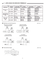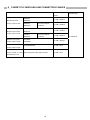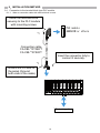
1
Analog Signal Conversion Module (Output type) FA-ATB8YTB FA-ATS*M1Y***** FA-ATFTMXY User's Manual Thank you for purchasing the FA Goods product. Before using the product, please read this User’s Manual and the relevant manuals carefully to ensure correct use. SAFETY PRECAUTIONS (Always read these precautions prior to use.) Before using this product, please read this User’s Manual and the relevant manuals carefully and handle the product properly with full attention to safety. The precautions presented in this manual are concerned with this product only. For programmable controller system safety precautions, refer to the user's manual of the programmable controller used. In this manual, the safety precautions are classified into two levels: " WARNING" and " CAUTION". WARNING Indicates that incorrect handling may cause hazardous conditions, resulting in death or severe injury. CAUTION Indicates that incorrect handling may cause hazardous conditions, resulting in minor or moderate injury, or property damage. Under some circumstances, failure to observe the precautions given under " CAUTION" may lead to serious consequences. Always follow the precautions of both levels because they are important for personal and system safety. 1 [Design Precautions] WARNING Configure external safety circuits to ensure that the entire system operates safely even when a fault occurs in the external power supply, the programmable controller, or the product. Failure to do so may result in an accident due to an incorrect output or malfunction. Configure a circuit to turn on the programmable controller and then the external power supply. If the external power supply is turned on first, an accident may occur due to an incorrect output or malfunction. [Design Precautions] CAUTION Do not bundle the control lines or communication cables together with the main circuit lines or power cables. Keep a distance of 100mm (3.94 inches) or more between them. Failure to do so may result in a malfunction due to noise. At power on/off, voltage or current may be instantaneously output from the output terminal of this product. In such a case, wait until the analog output becomes stable, and then start controlling the external device. [Installation Precautions] WARNING Be sure to shut off the external power supply for the system in all phases before installation. Failure to do so may result in an electric shock. 2 [Installation Precautions] CAUTION Use the product in an environment that meets the general specifications described in this User’s Manual. Failure to do so may result in an electric shock, fire, malfunction, or the product damage or deterioration. Use an output signal conversion device. Using an input signal conversion device incorrectly may damage the product. Securely fix the product with a DIN rail or mounting screws. Incorrect mounting may cause the product to malfunction, fail, or drop. When using the product in a vibration environment, secure the product by screws. Tighten the screws within the specified torque range. Undertightening can cause the product to drop, short circuit or malfunction. Overtightening can damage screws and/or the product, causing the product to drop, short circuit, or malfunction. Be sure to shut off the external power supply for the system in all phases before installing or removing the product. Failure to do so may damage the product, or cause the product to malfunction or fail. Do not directly touch any conductive parts and electronic components of the product. Doing so can cause the product to malfunction or fail. Hold the Installation base when transporting the Installation base with the Devices attached or when installing it to a panel. Holding the signal conversion device may cause the device to drop or fail. [Wiring Precautions] WARNING Be sure to shut off the external power supply for the system in all phases before installation and wiring. Failure to do so may cause an electric shock, or damage the product. 3 [Wiring Precautions] CAUTION Be sure to ground the FG terminal to the protective ground conductor dedicated to the programmable controller with a ground resistance of 100 Ω or less. Failure to do so may result in an electric shock or malfunction. Use applicable solderless terminals and tighten them within the specified torque range. If any spade solderless terminal is used, it may be disconnected when the terminal screw comes loose, resulting in failure. Check the rated voltage and terminal layout, and then wire the product correctly. Connecting a power supply with a different voltage rating or incorrect wiring may cause a fire or failure. Do not install the control lines or communication cables together with the main circuit lines or power cables. Keep a distance of 100mm (3.94 inches) or more between them. Failure to do so may result in malfunction due to noise. Place the cables in a duct or clamp them; if not, dangling cables may swing or be inadvertently pulled,, resulting in damage to the product or cables, or a malfunction due to poor connection. Tighten the terminal screws within the specified torque range. Undertightening can cause a short circuit, fire, or malfunction. Overtightening can damage screws and/or the product, causing the product to drop, short circuit, or malfunction. Tighten the connector screws within the specified torque range. Undertightening can cause a short circuit, fire, or malfunction. Overtightening can damage screws and/or the product, causing the product to drop, short circuit, or malfunction. Connect the connector to the product securely. Failure to do so may cause a malfunction. When disconnecting a cable from the product, do not pull the cable itself. For a cable with connector, hold the connector and pull it out. For a cable connected to a terminal block, loosen the terminal block screws before removing the cable. Failure to do so may result in a malfunction or damage to the product or cable. Before connecting the cables, check the type of interface to be connected. Connecting the cables to a wrong interface or erroneous wiring may cause the product or external devices to fail. Prevent foreign matter such as dust or wire chips from entering the product. Such foreign matter can cause a fire, failure, or malfunction. The product must be installed inside the control panel. Connect the main power supply to the product inside the control panel through a relay terminal block. Only qualified service personnel with knowledge of protection against electric shock should replace and wire the product. Keep a distance of 100mm (3.94 inches) or more between a thermocouple and the main circuit line or AC control lines. Also, keep the thermocouple away from a circuit that includes harmonics, such as a high-voltage circuit and a load circuit of an inverter. Do not place the product near a device that generates magnetic noise. When connecting the product to the programmable controller, check that the product configuration is correct. The modules may be failure or malfunction if the configuration is incorrect. 4 Attach the Device securely in the Base. Failure to do so may damage the Device and/or the Base, causing them to drop, or malfunction due to poor connection. And attach or remove the Device in a correct procedure. Failure to do so may damage the Device and/or the Base, causing them to drop, or malfunction due to poor connection. Use the product with no pressure applied to its connector. Failure to do so may cause a breakdown or disconnection. Attach the protection cover or device to an unused connector or slot of the product. Foreign matter on an unused connector or slot without protection may cause a fire, failure, or malfunction. [Startup and Maintenance Precautions] WARNING Do not touch any terminal while power is on. Doing so can cause an electric shock or malfunction. Be sure to shut off the external power supply for the system in all phases before cleaning the product or retightening the terminal screws, the mounting screws of the connector, or the fixing screws of the product. Failure to do so may result in an electric shock, or cause the product to fail or malfunction. Undertightening can cause the product to drop, short circuit, or malfunction. Overtightening can damage the screw and/or product, causing the product to drop, short circuit, or malfunction. [Startup and Maintenance Precautions] CAUTION Do not disassemble or modify the modules. Doing so may cause failure, malfunction, injury, or a fire. Use any radio communication device such as a cellular phone or PHS (Personal Handy phone System) more than 25cm (9.85 inches) away in all directions from the programmable controller, this product. Failure to do so may cause malfunction. Shut off the external power supply for the system in all phases before mounting or removing the module. Failure to do so may cause the module to fail or malfunction or damage. After the first use of the product, do not mount/remove the module, and the cable more than 50 times (IEC 61131-2 compliant) respectively. Exceeding the limit of 50 times may cause malfunction. Startup and maintenance of a control panel must be performed by qualified maintenance personnel with knowledge of protection against electric shock. Lock the control panel so that only qualified maintenance personnel can operate it. Before handling the module, touch a grounded metal object to discharge the static electricity from the human body. Failure to do so may cause the module to fail or malfunction. 5 [Disposal Precautions] CAUTION When disposing this product, treat it as industrial waste. [Transportation Precautions] CAUTION Avoid the shock that exceeds the shock resistance described in the general specifications during transportation, as the product is a precision device. Failure to do so can cause the product to fail. EMC and Low Voltage Directives Compliance with the EMC Directive, which is one of the EU Directives, has been mandatory for the products sold in European countries since 1996. Additionally, compliance with the Low Voltage Directive, another EU Directive, has also been mandatory since 1997. To prove the compliance with the EMC Directive and the Low Voltage Directive, manufactures must issue an EC Declaration of Conformity and the products must bear a CE marking. (1) Authorized representative in Europe The authorized representative in Europe is shown below. Name: Mitsubishi Electric Europe B.V. Address: Gothaer strasse 8, 40880 Ratingen, Germany (2) How to use the FA Goods in compliance with the EMC and Low Voltage Directives For information on how to conform to the EMC and Low Voltage Directives when incorporating the compliant FA Goods into a user's machinery or system, refer to "EMC and Low Voltage Directives Compliant Manual_50D-FA9010-108". 6 1.INTRODUCTION This user's manual explains the specification, handling, etc. of the Installation base (FA-ATB8YTB), and the Signal conversion device (FA-ATS*M1Y*****), and the I/O signal through device (FA-ATFTMXY) all of which the Analog signal conversion module consists of. By attaching the Signal conversion device to the Installation base, the Analog signal conversion module insulates the designated signals (1 to 5VDC, 4 to 20mADC) between input and output terminals, or among the channels, convert them to analog output signals, and outputs signals. 2.GENERAL SPECIFICATIONS Item Specifications Operating ambient temperature 0 to 55°C Storage ambient temperature -25 to 75°C Operating ambient humidity 5 to 95% RH, no condensation Storage ambient humidity 5 to 95% RH, no condensation Conforming standards Under Vibration resistance intermittent vibration Under continuous vibration Shock resistance JIS B 3502, IEC61131-2 Frequency Acceleration Amplitude 5 to 8.4Hz ― 3.5mm 2 8.4 to 150Hz 9.8m/s (1G) ― 5 to 8.4Hz ― 1.75mm 8.4 to 150Hz 4.9m/s2 (0.5G) 10 times each in X, Y, and Z directions ― ― Compliant with JIS B 3502 and IEC61131-2 (147m/s2 (15G), 3 times each in X, Y, and Z directions) Operating atmosphere No corrosive gas Operating altitude (* 1) 2,000m or lower Installation location Sweep count Inside the control panel Overvoltage category (* 2) II or lower Pollution level (* 3) 2 or lower * 1: Do not use or store the module under the atmospheric pressure greater than that at an altitude of 0m. * 2: Indicates the section of the power supply to which the equipment is assumed to be connected, between the public power grid and the machinery within the premises. * 3: This is a guideline indicating the degree of the generation of conducting substances in the environment in which a device is used. 7 3.PERFORMANCE SPECIFICATIONS 3-1. Installation base (FA-ATB8YTB) Model name Item Number of slots Terminal screw Terminal block Applicable wire, Tightening torque Module mounting Mounting screws DIN rail External supply power Current consumption (24VDC) Withstand voltage/ insulation resistance Weight FA-ATB8YTB 8 M3 screw, Pitch of 7.62mm, Self tightening screw with finger protector cover 2 AWG 22 to 14: 0.3 to 2.0mm (with solderless terminal use) 58.8 to 88.2N・cm (6 to 9kgf•cm, 5.22 to 7.5lbf•in, UL standard conformity tightening torque:59N•cm, 5.22 lbf•in.) M4 × 0.7mm × 20mm or greater Tightening torque range: 78 to 118N·cm (8 to 12kgf·cm) Applicable DIN rail: TH35-7.5Fe, TH35-7.5Al (IEC60715 compliant) 24VDC±10% 6mA or less (not includeing current consumption by the conversion device, the Signal through device, the programmable controller, and the monitor equipment) Between input/output/power supply: 750 VAC for 1 minute, 10MΩ or more About 320g *1: Attach the dummy device to an unused slot for covering an empty slot. *2: When connecting a cable to the Module, push the cable connector in until it is locked. *3: When the signal through device FA-ATFTMXY is used for output signal of 4 to 20mA from the programmable controller the voltage value according to the input resistance of the connected monitor equipment is detected for the monitor output. The current value can be found by dividing the detected voltage by the input resistance. ●Block chart Notes: Use the equipment with input resistance of adequate size for monitor output. (1MΩ or more is recommended.) The monitor output signal is 1 to 5V. Use shielded electrical cables for external wirings. An external power supply is connected to CON1 and CON2. Give the short-circuit prevention processing when the power supply is not used. ・Power supply terminal For 24V: Pin No.3 or 4 For 24G: pin No.1 or 2 ・Short-circuit prevention processing 1) Set the connector on PLC and monitor equipment side to NC (No connection). 2) Insulate pins at wire end for NC. 8 3-2. Signal through device (FA-ATFTMXY) Model name Item Number of points Conversion type Resistance Input Resistor accuracy Characteristic of temperature of resistor Permissible I/O signal Weight FA-ATFTMXY When signal is through - - 1 point (1 channel) When current is converted to voltage *7 250Ω ±0.1% or less ±0.0025% / °C or less - Voltage: 10V or less, Current: 20mA or less About 30g *7: When current is converted to voltage, short across terminals A and C of the Base terminal block. Input type: when current is converted to voltage Output type: when signal is through Input type: when current is converted to voltage Input type: when signal is through ●Block chart 9 3-3.Signal conversion device from current input to voltage output (FA-ATSAM1YV****) Model name Item Number of points Input range Input (PLC side) Input resistance Standard accuracy Accuracy (for full scale) Temperature characteristic Output signal Permissible load resistance Output Disconnection detection function *8 Response speed Zero/Span adjustment Power supply Current consumption (24VDC) Isolation method Withstand voltage/ insulation resistance Weight FA-ATSAM1YV05 FA-ATSAM1YV15 FA-ATSAM1YV010 FA-ATSAM1YV1010 1 point (1 channel) 4 to 20mA 250Ω ±0.1% or less (surrounding air temperature 25℃±5℃) ±0.015% / ℃ or less 0 to 5V 1 to 5V 0 to 10V -10 to +10V 2.5kΩ or more None 15ms or less Zero adjustment range:-2 to 2%,Span adjustment range:98 to 102% 24VDC±10% (supplied from the Base) 45mA or less Transformer insulation Between input/output/power supply :750VAC for 1 minute,10MΩ or more About 40g About 40g About 40g About 40g *8: It indicates time until output signal reaches 90% for startup pulse input. ●Block chart When the Signal through device is attached on the Base Output signal from PLC Output signal to monitor (MIL20P connector side) 4 to 20mADC External output signal (Terminal block side) 0 to 5VDC, 1 to 5VDC, 0 to 10VDC, -10 to +10VDC Zero/Span adjustment External power supply 24VDC 10 3-4.Signal conversion device from current input to current output (FA-ATSAM1YA****) Model name Item Number of points Input range Input (PLC side) Input resistance Standard accuracy Accuracy (For full scale.) Temperature characteristic Output signal Permissible load resistance Output Disconnection detection function 9 Response speed ※ Zero/Span adjustment Power supply Current consumption (24VDC) Isolation method Withstand voltage/ insulation resistance Weight FA-ATSAM1YA020 FA-ATSAM1YA420 1 point (1 channel) 4 to 20mA 250Ω ±0.1% or less (Surrounding air temperature 25℃±5℃) ±0.015% / ℃ or less 0 to 20mA 4 to 20mA 600Ω or less None 15ms or less Zero adjustment range:-2 to 2%,Span adjustment range:98 to 102% 24VDC±10% (supplied from the Base) 45mA or less Transformer insulation Between Input/Output/Power :750VAC for 1 minute,10MΩ or more About 40g About 40g *9: It indicates time until output signal reaches 90% for startup pulse input. ●Block chart When the Signal through device is attached on the Base Output signal from PLC Output signal to monitor (MIL20P connector side) 4 to 20mADC External output signal (Terminal block side) 0 to 20mADC, 4 to 20mADC Zero/Span adjustment External power supply 24VDC 11 3-5.Signal conversion device from voltage input to voltage output (FA-ATSVM1YV****) Model name Item Number of points Input range Input (PLC side) Input resistance Standard accuracy Accuracy (For full scale.) Temperature characteristic Output signal Permissible load resistance Output Disconnection detection function 10 Response speed * Zero/Span adjustment Power supply Current consumption (24VDC) Isolation method Withstand voltage/ insulation resistance Weight FA-ATSVM1YV05 FA-ATSVM1YV15 FA-ATSVM1YV010 FA-ATSVM1YV1010 1 point (1 channel) 1 to 5V 1MΩ or more ±0.1% or less (Surrounding air temperature 25℃±5℃) ±0.015% / ℃ or less 0 to 5V 1 to 5V 0 to 10V -10 to +10V 2.5kΩ or more None 15ms or less Zero adjustment range:-2 to 2%,Span adjustment range:98 to 102% 24VDC±10% (supplied from the Base) 45mA or less Transformer insulation Between Input/Output/Power :750VAC for 1 minute,10MΩ or more About 40g About 40g About 40g About 40g *10: It indicates time until output signal reaches 90% for startup pulse input. ●Block chart When the Signal through device is attached on the Base Output signal from PLC Output signal to monitor (MIL20P connector side) 1 to 5VDC External output signal (Terminal block side) 0 to 5VDC, 1 to 5VDC, 0 to 10VDC, -10 to +10VDC Zero/Span adjustment External power supply 24VDC 12 3-6.Signal conversion device from voltage input to current output (FA-ATSVM1YA****) Model name Item Number of points Input range Input (PLC side) Input resistance Standard accuracy Accuracy (For full scale.) Temperature characteristic Output signal Permissible load resistance Output Disconnection detection function 11 Response speed * Zero/Span adjustment Power supply Current consumption (24VDC) Isolation method Withstand voltage/ insulation resistance Weight FA-ATSVM1YA020 FA-ATSVM1YA420 1 point (1 channel) 1 to 5V 1MΩ or more ±0.1% or less (Surrounding air temperature 25℃±5℃) ±0.015% / ℃ or less 0 to 20mA 4 to 20mA 600Ω or less None 15ms or less Zero adjustment range:-2 to 2%,Span adjustment range:98 to 102% 24VDC±10% (supplied from the Base) 45mA or less Transformer insulation Between Input/Output/Power :750VAC for 1 minute,10MΩ or more About 40g About 40g *11: It indicates time until output signal reaches 90% for startup pulse input.. ●Block chart When the Signal through device is attached on the Base Output signal from PLC Output signal to monitor (MIL20P connector side) 1 to 5VDC External output signal (Terminal block side) 0 to 20mADC, 4 to 20mADC Zero/Span adjustment External power supply 24VDC 13 4.DEVICE ATTACHING/REMOVING (1) How to attach to the Base (2) How to remove from the Base 1) Set the Device to fit along the slot of the Base. 1) Hold the Device by the attaching/removing hook and the place on the opposite side so as to keep the hook pressed in. Attaching/ removing hook 2) Insert the Device until it is locked with the 2) Pull out the Device with the attaching/removing attaching/removing hook (until the hook clicks). hook pressed in. Attaching/ removing hook Note Use an output signal conversion device (with orange lines). Using an input signal conversion device (with purple lines) incorrectly may damage the product. Point (1) Hold the Installation base, not the devices, when transporting the Installation base with the Devices attached or when installing it to a panel. (2) The dummy device is available for an empty slot of the Base as a dust proof countermeasure. 14 5.MODULE INSTALLING ORIENTATION Vertical surface installing in landscape orientation Vertical surface installing in portrait orientation Horizontal surface installing 15 6.EXTERNAL DIMENSIONS 6-1. Installation base (FA-ATB8YTB) [Unit: mm] 6-2. Signal conversion device (FA-ATS*******) Signal through device (FA-ATFTMXY) [Unit: mm] 14.5 (53) 51 16 2 Connector pin array (right side view) 7.APPLICABLE SOLDERLESS TERMINALS ● Solderless terminal dimensions Round non-insulated solderless terminal Y non-insulated solderless terminal [Unit: mm] Round insulated solderless terminal Y insulated solderless terminal ● Terminal block shape [Unit: mm] 17 8.TARGET PLC MODULES AND CONNECTION CABLES PLC Module Model Connection Cable Model Q68DAIN FA-CBL**ATQ8YT MELSEC-Q series Q68DAVN Analog output module Q68DAIN Conversion adapter Q68DAVN FA-Q6TCA R60DAI8 R60DAV8 Analog output module R60DAI8 Conversion adapter R60DAV8 FA-Q6TCA A1S68DAI Analog output module A1S68DAV CC-Link Analog output module FA-CBL**ATQ8YA FA-CBL**ATQ8YT MELSEC iQ-R series MELSEC-AnS series FA-CBL**ATQ8YA FA-CBL**ATS8YT AJ65SBT2B-64DA FA-CBL**ATYF General-purpose analog output module FA-CBL**ATYF General-purpose analog output module of other Module Model manufacturers' PLC 18 FA-ATB8YTB 9.INSTALLATION METHOD 9-1.Connection to the terminal block type PLC module 9-1-1.When a connection cable with terminal block is used Install the terminal block securely to the PLC module with mounting screws PLC module Q68DAIN or others *1 Connection cable FA-CBL**ATQ8YT FA-CBL**ATS8YT Insert the connector fully to connect it securely. *1 Ground the FG wire to the panel (Ground both ends of the cable) Output signals 19 9-1-2.When conversion adapter between terminal block and connector is used Output signals 20 9-1-3.When cable with loose wires is used CC-Link, other manufacturers' PLC or others Wire the cable securely to the terminal block of PLC module Connection cable FA-CBL**ATYF Insert the connector fully to connect it securely. Ground the FG wire to the panel Output signals 21 10.PRECAUTIONS (1) Allow the product to warm up for ten minutes or more as a precaution though the Module works at the same time as powering it ON. (2) Because the Signal conversion device had been calibrated in the initial state, it is not necessary to be calibrated again. However, when the calibration is required for the conformity between the Device and other equipment to be connected, perform the Zero/Span adjustment as follows. (Trimmer operation・・・ Turning to the right (in clockwise) for increasing a value, Turning to the left (in counterclockwise) for decreasing a value) ① Allow the product to warm up for ten minutes or more after powering it ON supply of the module. ② Input the signal equivalent to 0% in the input range, and adjust output signal to 0% by using the Zero adjustment trimmer. ③ Input the signal equivalent to 100% in the input rang, and adjust output signal to 100% by using the Span adjustment trimmer. ④ Complete the Zero/Span adjustment by repeating the operation in step 2 and 3. ⑤ Input the signal of 25%, 50%, and 75% in the input range, and confirm the output linearity (3) When the monitor output is used, the handling is different according to the usage condition of the device. Please see the following tables about handling by each device. PLC analog output signal 4 to 20mA 1 to 5V 4 to 20mA 1 to 5V Signal conversion device Signal through device Installation base terminal block Monitor output *12, *13 FA-ATS*M1Y***** Various output signals 1 to 5V When signal is through 4 to 20mA *14 when current is converted to voltage When signal is through 1 to 5V 1 to 5V 1 to 5V 1 to 5V FA-ATFTMXY 1 to 5V *12:Use the measuring equipment with input resistance of adequate size for monitor output. (1MΩ or more is recommended) *13:Do not short across connector pins No.1 to 4 to 24V/24G for monitor output of the Installation base FA-ATB8YTB (output type). *14:The voltage value according to the input resistance (R) of the connected external monitor equipment is detected. The current value (I) can be calculated with the monitor output voltage (V) and the input resistance (R) by the following formula. I=V/R Example) When R (the input resistance of the connected external monitor equipment) = 500Ω, and V (the measured voltage value) = 5V, the formula for I (the detected current) is as below. 5V / 500Ω = 10mA 22 FOR YOUR SAFETY This product has been manufactured as a general-purpose product for general industry applications, etc. The product is not designed or manufactured to be used in equipment or systems in situations that can affect or endanger human life. When considering this product for operation in special applications such as machinery or systems used in passenger transportation, atomic power, electric power, aerospace, or medical applications, please contact your nearest Mitsubishi sales representative. Although this product was manufactured under conditions of strict quality control, the product shall be systematically provided with backup and fail-safe functions when it is used in facilities where breakdowns of the product are likely to cause a serious accident or damage. 1-13-5 Kudankita, Chiyoda-ku, Tokyo, Japan 102-8404 Our website URL: http://www.mee.co.jp/ Before using this product, ensure the safety in case of failure. We assume no responsibility for consequential damages caused by failure of the product. 50D-FA9010-123-B Specifications subject to change without notice. Published in May 2015 23