1
Safe Torque Off
vacon • 110
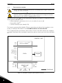
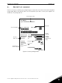
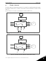
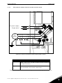
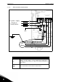
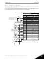
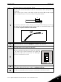
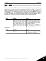
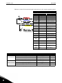
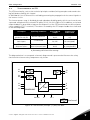
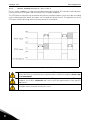
The picture below shows an example of connection for the STO function. The external device has to
be connected with 6 wires to the drive.
EXTERNAL DEVICE
S1
G1
R
S2
G2
R
=
L1
L2
L3
F+
F-
R
POWER UNIT
DC+/R+
U
V
3
R-
W
DC-*
R
Reinforced
Figure 73. STO example with automatic monitoring of the feedback and both STO inputs used.
(*) Only for MU3.
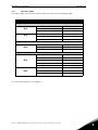
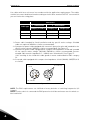
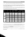
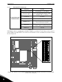
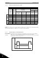
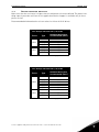
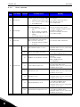
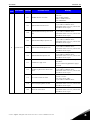
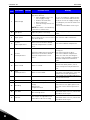
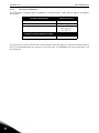
The external device has to monitor the STO function in accordance with theTable 45. The device has
to periodically de-energize the STO inputs and it has to verify that the STO output feedback assumes
the expected value.
Any difference between the expected and the real value has to be considered as a failure and has to
drive the system into a Safe State. In case of failure, check the wiring. If the fault recognized by the
external safety device persists, the drive will have to be replaced/repaired.
Service support: find your nearest Vacon service center at www.vacon.com
9