1
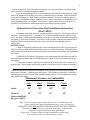
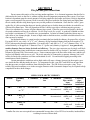
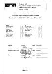
Kuma Stoves
Hayden, ID. USA
MODEL:
ARCTIC
(AR-7, AR-8, AR-10)
Fuel-oil stove
User Manual for:
-Installation
-Operation
-Servicing
This manual contains information necessary for the safe installation and operation of your Kuma Arctic either in residential or mobile homes. While most
anyone can install their oil stove, it is recommended that the installation be done
by a qualified installer familiar with fuel oil stoves, preferably an NFI (National
Fireplace Institute) Certified expert. We recommend contacting local building or
fire officials in your area regarding restrictions and installation inspection requirements. Please read this entire manual before attempting installation or operation
of this appliance. Improper installation or operation of this oil stove can result in
bodily or property damage.
*SAVE THESE INSTRUCTIONS*
Rev. 3/07
1
CONTENTS
Section 1– Stove placement, air requirements, Convection
shell installation Instructions, and clearances……….. pg. 1-2
2– The flue and flue connections………………………… pg. 3
3– Fuel tank installation and fuel line connections………. pg. 4
4– Lighting, adjustments to carburetor, and draft
stabilizer adjustments………………………………. pg. 5-7
5– Servicing…………………………………………….. pg. 7
6– Trouble-shooting guide……………………………..... pg. 8-9
7– Warranty……………………………………………… pg. 10
SECTION 1
Stove placement, air requirements, and clearances
Try to pick a location that will be somewhat central in the house or room in which you
wish to install the Arctic. Due consideration of the fuel tank location, ease of fuel line installation, and flue location is wise. You will want to read the fuel tank section to get a better idea of
where to locate the tank as well as the stove. The stove must be placed on hearth that is noncombustible, having a thickness of 3/8” or greater. A 36”x 36” hearth pad area is recommended. Once a location is established, the stove can be placed on the hearth and leveled. It is
absolutely imperative that your Arctic is level. There are adjustment bolts under each corner of
the pedestal base should these adjustments be necessary. Place a level on top of the pedestal
base both directions and adjust until level.
This unit has been tested to U.L. 307A and is approved for installation and use in manufactured homes. There are some special considerations when installing into a mobile or manufactured home. For model AR-10 (10” burner), the flue system must consist of a 4”,5” or 6”
diameter CLASS “A”, U.L. HT103 type insulated chimney, and a double-wall stove pipe connector. For models OC-7 and OC-8 (7” and 8” burner), a 4”,5” or 6” diameter Class “A” insulated chimney may also be used, or you may use an approved 4” diameter Class “L” (pellet
vent) chimney. Dura-Vent D.V.L. double-wall connector is required or 4” diameter Class “L”
vent may be used as a connector. As a general rule, smaller diameter flues are better for
draft and efficiency. For clarification see the chimney/connector table at the end of Section 2.
Single wall stove pipe connector may be used on residential installations (not for manufactured/
mobile homes). The manufactured home installation also requires an outside combustion air
source. For outside combustion air a 4” diameter or larger duct should be installed vertically
through the hearth and floor directly below the stove or horizontally through the wall connecting to the 4” opening at the stove back (flex ducting may be used). Make sure there is a rodent
screen with a maximum 1/4” x 1/4” opening placed in the duct to prevent rodents from accessing the stove. (Continued)
2
A storm or dryer type vent with a screen is adequate. For your convenience, an outside air kit
(part # 4OAVK) is available through your dealer.
If you are not installing this stove in a mobile home, and outside air is not desired, simply
remove the outside air cover at the stove back so ambient room air can enter. Please note that at
certain draft conditions (i.e. high winds) a significant amount of air may be needed to achieve a
proper burn. Consideration of open windows or an air source near the stove will probably be necessary depending on the “air-tightness” of your home. Again, outside air to your oil stove is a
good idea as it will make the combustion impervious to house pressure problems.
Optional Arctic Convection Shell Installation Instructions
(Part# ARCS)
An optional convection shell may be purchased from your dealer. This shell provides two
functions: 1) Increased air flow. It provides a 3/4” jacket surrounding the sides and back of the
stove. The shell is vented at the bottom and top to promote convection air movement throughout
your home. 2) Decreased clearances. You will see in the clearance section of this manual that installation of this convection shell allows the Arctic to be installed considerably closer to
combustibles.
INSTALLATION:
1. Remove from the box and place the convection shell down over the stove from the top.
There are spacers welded inside that provide the correct rear and side spacing. Slide shell down
until it rests on the pedestal base then pull forward to ensure that the shell spacers are touching the
stove back.
2. Install the 4 self-drilling, self-tapping screws at the front of the side panels top and bottom with a high speed drill and a #2 Phillips driver bit. Screw all four screws until snug, do not
over tighten.
3. Installation complete. Stow the label under the stove bottom after all clearances have
been checked. The top hinges up allowing exposure of the firebox top for cooking or warming.
*Please note that these clearances are minimums. It is a good idea to exceed these clearances
unless space is limited. Common sense must prevail. The clearances are listed on a label that is
attached to the stove by a lanyard. After installation the label may be stowed under the unit. DO
NOT REMOVE LABEL.
Minimum Clearances to Combustibles
Sides
Back
Flue Pipe
Corner
Arctic
28”
26”
18”*
23”
Arctic w/
Convection Shell
14”
15”
6”*
12”
Kit. (part # ARCS)
Note: Corner clearance applies only when the stove is installed in a room
corner with the stove placed perpendicular to the corner (45 degrees).
MAKE SURE THAT ALL MINIMUM CLEARANCES ARE MET OR EXCEEDED
*Clearances to flue pipe are for single-wall connectors. A double-wall
connector is required for mobile home installations.
Please note: Clearances differ on single and double-wall flue pipes.
Cross reference to be sure all clearances are met.
3
SECTION 2
The flue and flue connections
Do not connect this unit to a flue servicing another appliance. It is of utmost importance that the flue be
dedicated to the Arctic as the flue is, without a doubt, the most important component of the system. Good combustion is dependent upon the correct amount of air being supplied to the burner at all times, which is dependent
upon a correct negative flue pressure. Draft is caused by the gases inside the flue being hotter and lighter than
the air outside, thus the rising heated gases carry out the products of combustion. Since the flue “sucks” gases
up the flue, it is this suction that draws air into the pedestal area to feed the burn pot with the air needed for an
efficient, blue-flame burn. This will depend on the flue’s ability to provide a consistent negative pressure.
There is no substitute for a warm, efficient chimney/pipe system. If the flue gases cool too quickly, draft will
slow and combustion will not be as efficient. Do not skimp on the flue system. A good rule of thumb on chimney height is a minimum of 12’ from the stove to termination. Location of chimney and other factors may require more or less chimney height. In areas of high winds or draft inversions, a suitable wind-directional or vacuum cap may be needed.
An insulated chimney is a must in order to maintain the heat inside the chimney for proper flow of gases.
For model AR-10, use a class “A”,4”,5” or 6” diameter, all-fuel insulated chimney that has been tested to U.L.
HT103 when passing through combustibles. For models AR-7 and AR-8, a 4”, 5”, or 6” diameter Class “A” insulated chimney or an approved 4” diameter Class “L” (pellet vent) chimney is approved. As a general rule,
smaller diameter flues are better for draft and efficiency. The stove pipe connector may be single-wall black
pipe with tight fitting joints (mobile home connectors must be double-wall, see Section 1), and must be securely
fastened at all joints with 3 sheet metal screws. Fasten connector pipe to the flue collar on the stove and the ceiling box/wall thimble with screws as well. The Arctic may also be connected to a masonry chimney, but it will
need to be lined with a stainless steel liner and insulated as well. Use and install all piping according to the
manufacturers listed clearances.
Certain atmospheric conditions such as high winds will cause a change (increase) in the negative pressure inside the flue and thus inside the stove. To compensate for this, your AR-7 and AR-8 has an upper burn
ring that prevents over-draft conditions from affecting the burn. The AR-10 does not require a ring. In extremely high wind conditions, a tee in the stovepipe connector with a barometric damper may be required to help
compensate for these draft changes.
SIZING YOUR ARCTIC CHIMNEY
Model:
Chimney
Type:
4” diameter 5” diame- 6” diameter Connector
Pipe: mobile
ter
home
installation
Connector
pipe:
residential
installation
Approved
double wall
only.
Single or
double wall
connectors
Approved
double wall
only.
Single or
double wall
connectors
Approved
double wall
only.
Single or
double wall
connectors
AR-7
Class “A”
or “L”
Recommended
AR-8
Class “A”
or “L”
Recommended
AR-10
Class “A” Recommended
only
OK
Not
Recommended*
OK
Not
Recommended*
OK
OK
*smaller flue sizes are not required but recommended because there is less BTU loss in smaller, insulated flues
resulting in a more efficient draft.
4
SECTION 3
Fuel tank installation and fuel line connections
OIL:
Your Kuma Arctic comes with a carburetor set for an average of a 2.35 cc. viscosity rating. You should be able to burn either #1 or #2 fuel with adjustments to the carburetor. A special high viscosity carburetor is available for burning bio-diesel if desired. Due consideration to
fuel grades should be noted. #1 Fuel oil, K-1, or kerosene will burn much cleaner than #2 fuel
and requires less maintenance. #2 fuel or diesel grades of fuel are fine to burn, however there
are combustibles present in # 2 fuel that become solids when they are burned, thereby requiring
more frequent cleaning of the decoker and burner.
TANK:
The fuel tank should be clean (second-hand tanks not recommended), so a new tank is
advised. Steel tanks require more maintenance such as painting to prevent rust. A tank with a
larger capacity will require less fillings as well as an opportunity to obtain better pricing for fuel
oil in greater quantities. Avoid placing the tank in direct sunlight. Warm tanks will condense
moisture which will fall to the bottom of your tank where it will need to be drained to prevent
valve damage and/or freezing and stopping oil flow. Also, due consideration should be given to
accessibility to the tank for delivery trucks.
The ideal tank should have two bottom-end outlets: one for fuel supply to the stove, and
one to drain off any water and dirt. To be able to do this, the tank must be installed with a
“fall” of at least 1/4” per foot of tank length. The fuel supply will come from the high end of
the tank and the lower end will be used for draining condensation and impurities. If the tank
has only one outlet, be sure to tip the tank away from the outlet slightly, as described above.
Brick or cement foundation for the tank is advised.
To provide correct pressure of the fuel supply to your stove, the tank outlet should be
between 16” and 72” above the carburetor on the stove. Do not exceed 72” above the carburetor as excessive head pressure could limit the carburetor’s ability to shut off fuel flow. Be sure
the support system under the tank is safe and adequate as a full 300 gallon tank will weigh
about 2000 lb.
If you must install a tank below the stove, or above the recommended height, a lift pump
and/or a level control valve must be fitted. You will need to check local building codes regarding such installations.
CONNECTIONS:
There should be 2 valves on a typical installation: 1) a shut-off valve at the tank to allow
service to any piping, or changing the main filter and 2) a shut-off valve close to the stove to be
able to isolate the stove for any maintenance, and (if required by code) a fire valve right before
the fuel pipe enters the building which would automatically shut off the oil supply in the
unlikely event of the stove overheating. Piping to the stove from the tank may be either steel or
copper, but copper is preferred to prevent any rusting problems. When making the fuel line
connection with the copper line from the tank to the stove, it is best to have a gradual slope or
“fall” on the line (i.e. no dips or kinks) so as to prevent any air bubbles or collection of dirt or
other impurities. A 3/8” diameter copper supply line is recommended and either compression
type or flare type fitting may be used. Finally, a good quality filter that also traps water should
be placed at the tank to ensure a good, clean supply of oil to your stove. The carburetor on the
stove is equipped with a screen-type filter but it is not intended for use as the primary filter.
5
SECTION 4
Lighting and carburetor adjustments
PRE-LIGHTING CHECKS:
The installation should be inspected to ensure that the work is complete and the workmanship is satisfactory. No stove should be lit if any part of the installation does not comply with the
relevant standards and regulations.
The oil tank should be examined to confirm there is a supply of the correct grade of oil,
that a filter and a working isolation valve are fitted. Having verified that the oil pipe work up to
the stove is complete and that the fire valve (if used) is closed, the tank isolation valve should be
opened and the pipe work inspected for leaks. The pipe into the inlet of the metering valve should
be uncoupled, the shut off valve opened and a minimum of one quart of oil collected into a suitable receptacle. If dirt or water is present in this sample, additional oil should be allowed through
the pipe work until it is free from contaminates. The fuel pipe work should be reassembled and all
connections checked for leaks and tightened as necessary.
For 7” Burner Models: Laying on top of the catalyst inside your AR-7 burner model
stove is a stainless steel top burn ring. It is important that the ring be in the proper position. It
comes in the proper position from the factory. Should the height of this ring change, it is easy
to re-adjust by bending the three tabs that rest on the catalyst top up or down. It is very important that the “cupped” part of the ring is facing up (as if it would hold water). The stove will
not burn properly if the ring is face down. Locate the two continuous rows of air holes circling
the burner top. The top ring tabs should set on the catalyst top so that the outer edge of the ring
comes out right between those two rows of air holes. In 8” models there is a flat upper burn
ring that lays face up on the burner top, the cupped part of the ring facing up. The top row of
holes should be visible.
LIGHTING:
Initial lighting should be undertaken by a qualified technician, with a suitable probetype manometer for checking the flue pressure.
The most efficient method of tuning the stove is at the start and with the proper equipment. The customer who will be operating the stove is an important partner in this process, so a
full understanding of how the stove operates and is maintained is invaluable.
Shortly after the stove is lit an air pressure reading should be taken to see if the draft
pressure readings are suitable. To take this reading, drill a hole suitable for the manometer
probe size in the stove pipe directly above the stove outlet. After pressure readings are finished,
simply plug the stove pipe hole with a suitable sized screw.
Lighting the stove:
1. Remove the catalyst (stainless steel mesh cylinder) and top burn ring (AR-7
& AR-8 only) from the burn pot.
2. Turn all supply valves on.
3. Turn control knob on carburetor to setting 1.
4. Press on/off control lever on carburetor to start (it pulls up and clicks to shut
stove off and pushes or clicks down to on position).
5. When a small amount of oil begins to appear in the burner bottom, take a
wooden kitchen match and light the oil (a small piece of crumpled tissue
paper can be lit and tossed into the burner if desired, or use of an alcohol-gel
fire starter is preferred).
lighting instruction continued on the next page
6
6. When oil is lit, replace the catalyst/ top burn ring and shut the door (a slightly
cracked door is helpful for a short period of time to aid initial light-up of oil,
but should not be required for more than 30 seconds). Until the flue pipe
warms up and draft is initiated, your Oil Classic will burn with a high,
yellow/orange flame. This is normal during start-up. It is simply burning off
excess liquid oil that accumulates in the burner bottom before the catalyst
turns red and begins to vaporize the fuel.
7. Within a few minutes, the stove burner should begin burning blue at flame
base and yellow at flame tip.
8. Run the stove for at least 30 minutes on low or medium to allow the whole
stove and chimney to come up to operation temperature.
9. You are now ready to adjust or “tune” your Oil Classic according to the
following carburetor adjustment section.
CARBURETOR ADJUSTMENTS:
Your Oil Classic has a carburetor that has both low-fire (setting 1) and high-fire (setting
6) adjustment screws on the top. They are small slotted screws that are of red color and may
need to be adjusted for correct flame size.
Both low- and high-fire settings have been pre-set at the factory, but depending on your
choice of fuel (#1 or #2 grade), these will usually need to be adjusted for the viscosity of fuel
you are using. Please note that after initial warm-up, it is important to adjust the high flame
first, then the low flame as any adjustments made to the high can affect the low, but not viceversa. Below is a description of what the flame should look like at both low– and high-fire:
Low-fire:
The flame should be totally blue with blue flame “spears” or jets dancing between the inner wall of the burn pot and the catalyst. The catalyst will be dull red to bright red.
There will be blue flame appearing around the fire ring at the burner top. You can decrease the
setting to where there is only the blue spears in the burn pot and little activity of blue flame at
the burner top. However, if there is any yellow flame in the burn pot on low setting, then the
low-fire adjustment screw needs to be increased to a total blue flame condition. Please remember that although the fuel consumption figures can be attained, there always needs to be enough
BTU loss (fuel consumed that is energy loss up the pipe) in order to maintain an efficient draft.
Thus a smaller, well insulated chimney is highly recommended.
High-fire:
The flame should be bright yellow with a 2/3 fire-box height to where the flame
will begin to break up and terminate just a few inches under the firebrick baffle. The base of
the flame at the burner ring should still be blue, and the catalyst will be a dull red. If the flame
is too high and allowed to impinge on the firebrick baffle too much, the result will be a cooling
of the flame tip, and incomplete combustion, thereby producing smoke and soot. Adjust the
high-fire adjustment screw to achieve proper flame size.
*EACH ADJUSTMENT OF NO MORE THAN ONE-QUARTER TURN
SHOULD BE ALLOWED TO STABILIZE FOR FIVE MINUTES BEFORE MAKING
ANY FURTHER ADJUSTMENTS ON EITHER HIGH– OR LOW-FIRE.
*MAKE SURE THE FLUE AND STOVE IS WARMED UP BEFORE MAKING
ANY CARBURETOR ADJUSTMENTS.
7
The carburetor on your Arctic has a main float valve internally to regulate the oil level
in the stove. It also has a separate, second safety float that can trip off if the oil level becomes
too high in the carburetor. Should this occur, you can reset the safety lever by clicking it back
down to start. You may need to reset the lever several times before the level of oil in the carburetor returns to a normal level. Your Arctic has been rigorously tested to both U.L. 896 and
U.L. 307A for both residential and mobile homes, and should the fire snuff out for any reason,
the carburetor will not allow more than 3/4” of oil in the bottom of the burner.
IT IS IMPERATIVE THAT THE STOVE IS BURNING PROPERLY AS EXPLAINED ABOVE. A POOR DRAFT OR POORLY ADJUSTED STOVE COULD
CAUSE THE STOVE TO SOOT AND BUILD UP GASES INSIDE THAT COULD
CAUSE THE STOVE TO GO OUT AND THEN RE-IGNITE ON ITS OWN. THESE
FUEL RICH GASES CAN BE EXPLOSIVE.
Should the fire go out for any reason, NEVER ATTEMPT TO LIGHT A HOT STOVE!
Try to determine why the stove went out and then allow the stove time to cool for 30 minutes before
re-starting following the lighting instructions in this manual. If you have any questions about the
operation of your Arctic please check the trouble-shooting section of this manual or call your
dealer.
SECTION 5
Servicing
ANNUALLY:
*Remove catalyst and fire ring and inspect and clean out burn pot of any build-up or
debris.
*Check flue and clean out soot build-up.
*Clean out stove interior and drip pan.
*Lightly brush off catalyst and inspect for deterioration– replace if necessary.
*Check all gaskets: rope seal around door and window seal (check for loose glass– no
need to remove).
*Check oil tank for damage or leaks and clean or replace main tank filter.
*Check all lines and connections for leaks or deterioration.
*A draft reading should be taken for low– and high-fire before operation.
QUARTERLY:
*Turn stove off and allow to cool.
*Remove catalyst and clean out any carbon deposits from burner bottom and oil inlet
inside burner (may need to clean deposits more frequently if using #2 fuel).
WEEKLY:
*The de-coking rod must be operated at least once per week to eliminate carbon
deposits that build up where oil enters the burner bottom:
1. Remove front burner access cover.
2. Slightly back brass packing nut off (counterclockwise) to release de-coking
rod. (Be careful as packing nut may be hot. A glove may be necessary.)
3. Slowly draw rod out until it stops while rotating 360 degrees several
times. A small pair of pliers or vise grips may be helpful. This rod has a
scraper internally that scrapes away carbon from inside the line.
4. While still rotating, push the rod back in until it stops and tighten the packing
nut snugly.
5. Replace access panel.
*Note: If flame is burning lower than expected, you probably have carbon build-up in
the line or burner bottom near fuel inlet.
8
SECTION 6
Trouble-shooting guide
CONDITION:
1. Oil present in burner with the carburetor in “off” position.
2. No oil in burner bottom after carburetor is turned on.
3. Flame smoky when lit.
4. Flame smoky when burning low.
5. Flame smoky when burning high.
6. Flame goes out on low.
7. Flame goes out in high winds.
8. Burner goes out and will not re-light.
9. Flame is noisy (buzzing or roaring) or separating from the burner on high-fire.
10. Flame size seems lower than normal while on high.
11. Dirty or sooty glass.
12. Oil smell in room.
POTENTIAL PROBLEM:
1. -Carburetor had been left on previously without the burner being lit.
2. -Shut-off lever tripped off, and needs to be pressed to start.
-One of the valves in the oil supply line shut off.
-No oil in the tank.
-Carburetor control plate stuck (tap on carburetor lightly).
-Air lock in supply line.
-Plugged filter (either primary filter or carburetor filter).
-Condensed water in supply line that has frozen in cold weather.
3. -Stove door not closed tightly.
-Carbon deposits at oil entry (operate de-coking rod).
-Cold flue.
-Plugged flue.
-Wind conditions causing pressure to be out of limits.
-Faulty catalyst.
4. -Any problems in (3) above.
-Dirt, carbon, or residue in burner bottom or fuel connection at burner
(operate de-coker).
-Low-fire set too low on carburetor (adjust, see section 4).
9
5. -Carburetor out of adjustment (decrease high-fire screw).
-Cold flue.
-Flame set too high (flame impinging on baffle too much).
-Faulty gasket (door rope, glass seal, or relief plate seal).
-Excessive residue in burner bottom.
6. -High wind, or unstable draft condition.
-Incorrect carburetor setting (increase low-fire screw).
-Faulty carburetor. (rare condition)
7. -Abnormally high, gusty winds (If you live in a windy area, a draft stabilizer
may need to be installed in the pipe to compensate).
-A wind-directional cap or vacuum cap may be helpful to prevent wind gusts and
down drafts from affecting pressure.
8. -No oil in tank.
-Valve in fuel supply line shut inadvertently.
-Fuel supply blocked (plugged filter, frozen water).
-Carburetor on/off lever tripped.
9. -Stove door having been open for a while and then shut (a roaring noise can occur for
a short period until draft stabilizes).
-Draft pressure too high - adjust carburetor to decrease high flame size, or add a tee
in connector pipe with a draft stabilizer
10. -Carbon deposits (operate de-coking rod).
-Draft pressure too high.
11. -Carburetor adjusted too high, allowing too much flame impingement on stove top.
-Flue plugged or dirty.
-Dirty burner or plugged fuel inlet (operate de-coker/clean burner bottom)
-House pressure problem (inadequate supply of air to stove, or fans operating in the
house increasing negative house pressure).
-Faulty or deteriorated catalyst.
-Blocked or inhibited air supply to stove (check outside air supply to stove or room).
-Faulty gasket (door rope, glass seal, relief plate seal, or burner gasket).
12. -Oil leaking from any connection.
-Poorly adjusted burner
-low flue pressure due to chimney size or geographic conditions affecting draft.
Consider smaller flue size to increase negative draft pressure.
10
SECTION 7
Limited Lifetime Warranty
Your Kuma Arctic is warranted against defects in materials or workmanship according
to the following:
*Stove body, all welded steel components– Lifetime, to the original purchaser.
*Burning system (stainless steel burn pot, catalyst, carburetor, fuel line supplied
with stove)- 2 years
Warranty does not cover gold plated door surface, normal maintenance items such as
paint, glass, and gasket. This warranty does not apply in cases of abuse, mishandling, unauthorized repair, alterations, failures, or operating difficulties due to misuse, accident, misapplication, improper installation, improper maintenance or service. Kuma Stoves reserves the right
under this warranty to repair, replace, or authorize repair of the defective stove or part at its discretion. Any warranty concerns should be directed to the authorized dealer.
A WORD ABOUT CERAMIC GLASS:
Your Kuma oil –burning stove has a glass front installed that is constructed of transparent high temperature ceramic glass. When any type of fuel is burned, certain chemicals are released in the combustion process. This release, combined with expelled moisture can cause a
stress factor on the glass surface. Fuel oil has sulphur in it and the sulphur can contribute to this
stressing phenomenon which results in micro-crazing. Micro-crazing appears as very fine stress
fractures that look like fine spider webs. It generally does not indicate a structural problem with
the glass– it is only cosmetic. As this is a by-product of combustion and not a defect in the
glass itself, the glass on your stove is an item that is not covered under the warranty of this
stove. There seems to be almost no issues of micro-crazing when burning #1 fuel oil or kerosene. However, #2 grade fuels or diesel inherently have a higher sulphur content making it
more susceptible to micro-crazing. There are other advantages to using #1 fuel, such as cleaner
burning and less carbon build-up. Contact your dealer if you have any questions or need a glass
replacement.