1
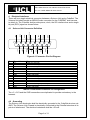
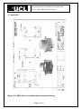
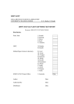
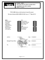
Project: QB50 MULLARD SPACE SCIENCE LABORATORY UNIVERSITY COLLEGE LONDON Author: D Kataria TITLE: QB50 Science Unit Interface Control Document Document Number MSSL-QB50-ID-12001 Issue 1 1st March 2012 MSSL Dhiren Kataria Alan Smith Craig Leff Mark Hailey Rahil Chaudery Hubert Hu Berend Winter Peter Coker Alan Spencer X X X X X X X X X VKI Jean Muylaert Ruedeger Reinhard Cem Ozan Asma Daniel Faber X X X X ISIS Jeroen Rotteveel Cesar Bernal Joost Elstak X X X Authors: D. Kataria Date: 01/03/2012 Manager/Project Office C. Leff Date: 01/03/2012 PA: A. Spencer Date: 01/03/2012 Page 1 of 11 Title: QB50 Science Unit Interface Control Document Doc. No. MSSL-QB50-ID-12001 Issue 1 CHANGE RECORD Issue Date Sections changed Issue 1 01/03/2012 All new Comments First issue Page 2 of 11 Title: QB50 Science Unit Interface Control Document Doc. No. MSSL-QB50-ID-12001 Issue 1 CONTENTS 1 Introduction ............................................................................................................ 4 2 Normative and Informative documents ............................................................... 4 2.1 Normative Documents ................................................................................... 4 2.2 Informative Documents .................................................................................. 4 3 Abbreviations ......................................................................................................... 5 4 Electrical Interfaces ............................................................................................... 6 4.1 Science Unit Connector Definition................................................................ 6 4.2 Grounding ....................................................................................................... 6 4.3 EMC requirements .......................................................................................... 7 4.4 Power Budget ................................................................................................. 7 5 Command and control interface ........................................................................... 7 5.1 Data Handling and Control ............................................................................ 7 5.2 Telemetry and Telecommands ...................................................................... 7 5.2.1 Telemetry ...................................................................................................... 7 5.2.2 Telecommands ............................................................................................. 8 5.3 RDY Flag ......................................................................................................... 8 5.4 Example Sequence Table .............................................................................. 8 6 Mechanical interface ............................................................................................. 8 6.1 Accommodation and Field of View ............................................................... 8 6.2 Interface control drawing ............................................................................... 8 6.3 Surface finish .................................................................................................. 9 6.4 Mass ................................................................................................................ 9 7 Attitude Control ..................................................................................................... 9 8 Cleanliness and Contamination ........................................................................... 9 9 Operating Conditions ............................................................................................ 9 10 Handling .............................................................................................................. 9 11 Thermal ............................................................................................................... 9 12 Appendix 1 ........................................................................................................ 11 Page 3 of 11 Title: QB50 Science Unit Interface Control Document Doc. No. MSSL-QB50-ID-12001 Issue 1 1 Introduction This document controls the required interfaces between a QB50 CubeSat and a QB50 Science Unit. Science Unit: As described in the call for proposals, the menu of sensors selected for the science units is: Ion Mass Spectrometer (IMS) Neutral Mass Spectrometer (NMS) Flux-Φ-Probe Experiment (FIPEX) Multi-Needle Langmuir Probe (MNLP) Corner Cube Laser Retroreflectors (CCR) Thermistors/thermocouples/RTD (TH) A Science Unit will comprise a subset of the above list. The design objective for the Science Unit is to remain within a 600 mW power budget (duty-cycled, orbit averaged), 600 g mass budget and half a CubeSat unit volume budget (excluding forward protuberance). 20% design margin is being held within these budgets. As the final configuration of the Science Unit to be provided to each of the CubeSat teams will only be made known after selection, representative mechanical and electrical interfaces with an overall resource envelope of the design objective are provided here. The location and interface of Thermistors within the body of the CubeSat will be included in a later version of this document. The location and interface of the Corner Cubes, if selected, will be included in a later version of this document. 2 2.1 Normative and Informative documents Normative Documents ND1: UM-3: CubeSat Kit User manual Rev D2 issued 17 Sep 2003. 2.2 Informative Documents ID1: Call for CubeSat Proposals for QB50 issued 15 Feb 2012 ID2: QB50 SSWG Final Report to be issued 1 Mar 2012 Page 4 of 11 Title: QB50 Science Unit Interface Control Document Doc. No. MSSL-QB50-ID-12001 Issue 1 3 Abbreviations ADC Analogue to Digital Converter CEM Channel Electron Multiplier DAC Digital to Analogue Converter EGSE Electronic Ground Support Equipment EMC Electromagnetic Compatibility EMI Electromagnetic Interference ESD Electro-Static Discharge FMMU Flash Mass Memory Unit FPGA Field Programmable Gate Array HSDR High Speed Data Recorder HV High Voltage I/F Interface IMS Ion Mass Spectrometer kbps kilo bits per second LEO Low Earth Orbit LV Low Voltage LVDS Low Voltage Differential Signalling MSSL Mullard Space Science Laboratory NMS Neutral Mass Spectrometer PCB Printed Circuit Board PWM Pulse Width Modulator S/C Spacecraft SEE Single Event Effects SMD Surface Mount Device SPI Serial Peripheral Interface TBC To be confirmed TBD To be decided TBI To be included Page 5 of 11 Title: QB50 Science Unit Interface Control Document Doc. No. MSSL-QB50-ID-12001 Issue 1 4 Electrical Interfaces There will be a single electrical connector between a Science Unit and a CubeSat. The Science Unit shall provide an MDM15-male connector for the CUBESAT side harness to attach to. The CubeSat shall provide power, clock, the I2C interface bus and a single bit port (RDY) signal as shown below. GND GND SCN SCN SCL SCN SDA SYS_CLK RDY +3V3 +5V SCN +3V3 Science Unit Connector Definition +5V 4.1 Figure 4-1 Connector Pin-Out Diagram Pin Signal Name Comment 1 2 3 4 5 6 7 8 9 10 11 12 13 14 15 +5 +3V3 SCN SYS_CLK SDA SCN GND +5 +3V3 RDY SCN SCL SCN GND Power for +5V logic Power for +3V3 logic Screen for SYS_CLK 7.4 MHZ (TBC) S/C system clock Not used I2C serial data signal Screen for SDA System GROUND Power for +5V logic Power for +3V3 logic This may connect to any available INPUT port pin on the S/C processor. Screen for RDY I2C serial clock signal (100 kHz) Screen for SCL System GROUND Table 4-1 Instrument Connector Pin Assignment The +5, +3V3 and the GND connections are duplicated to provide redundancy in the harness. 4.2 Grounding The Science Unit electronics shall be electrically grounded to the CubeSat structure via GND. The Science Unit Chassis is electrically connected to the CubeSat structure at its points of attachment. The electrical resistance shall be <50 mΩ. Page 6 of 11 Title: QB50 Science Unit Interface Control Document Doc. No. MSSL-QB50-ID-12001 Issue 1 4.3 EMC requirements TBI 4.4 Power Budget The power budget is shown in Table 4-2. These numbers are preliminary TBC and include the 20% design margin. Mode Power at +5V (mW) Power at +3.3V (mW) Orbit average Peak Orbit average Peak Standby 3 279 1 100 Science Mode 499 640 77 100 Table 4-2 Power Budget 5 Command and control interface 5.1 Data Handling and Control The I2C interface shall be used to control the instrument from the CubeSat. The I/F shall nominally operate at 100 kHz clock speed. The Science Unit is treated as a device on the I2C bus. It shall have a fixed address, set within the Science Unit. A buffer (size TBD) shall be provided in the Science Unit to store the science data & associated parameters. Data shall be transmitted from the Science Unit to the CubeSat computer over the I2C interface on command from the CubeSat computer. 5.2 5.2.1 Telemetry and Telecommands Telemetry The following telemetry packets shall be issued by the Science Unit to the CubeSat:Telemetry Packet Science Packet House-Keeping Packet Engineering Packets Table 5-1 Telemetry The packet formats shall follow the I2C protocol and will be provided in a subsequent release of the ICD. Page 7 of 11 Title: QB50 Science Unit Interface Control Document Doc. No. MSSL-QB50-ID-12001 Issue 1 Telecommands 5.2.2 Telecommands will be issued by the CubeSat to the Science Unit according to the science operations plan being executed. Command sequences from ground shall be time-tagged. The Science Unit will execute commands immediately upon receipt. 5.3 RDY Flag The Science Unit shall provide a RDY level sensitive flag signal to indicate when the SCIENCE DATA are available. The CubeSat computer shall monitor the RDY bit to determine when to perform a Science Packet read operation. The packets must be time-stamped by the CubeSat within 1s of the packet generation. 5.4 Example Sequence Table Below is given a pseudo sequence example of how the Science Unit would be run. There may be several (TBD) sequences uploaded and stored in CubeSat memory, which would be run at predefined times (i.e. time-tagged). Command Time Comment SU_ON t0 Turn ON power to Science Unit; Unit will go to Standby RUN_SCIENCE t1 Science Unit operational mode. STDBY t2 Go to Standby mode. SU_OFF t3 Turn OFF power to Science Unit Table 5-2 Example Sequence Table 6 6.1 Mechanical interface Accommodation and Field of View The Science Unit will be accommodated at one end of the CubeSat, on a 10 x 10 face. The vector normal to this face shall be in the spacecraft ram velocity direction. This face shall not be available for Solar cells, any other sensor or subsystem and nothing must project forward of this face. 6.2 Interface control drawing The mechanical interface drawing is provided in Appendix 1. The Science Unit is designed to interface to commercially available CubeSat structures either through an adapter or through appropriate relocation of mounting holes on the structures. Page 8 of 11 Title: QB50 Science Unit Interface Control Document Doc. No. MSSL-QB50-ID-12001 Issue 1 6.3 Surface finish The overall finish for the Aluminium structure of the Science Unit shall be Alocrom 1200. 6.4 Mass The total Science Unit mass shall be < 600 grams. 7 Attitude Control The CubeSat shall provide attitude control with a pointing accuracy of +/-10° and pointing knowledge of +/-2° (TBC). 8 Cleanliness and Contamination The CubeSats shall maintain an ambient pressure due to outgassing of < 5x10⁻⁶ mb. 9 Operating Conditions The particular operating conditions will depend upon the selection of sensors for a given Science Unit. These will be made known at the time of selection. 10 Handling The Science Unit shall be handled in a cleanroom environment (details TBI). ESD protection protocols shall be followed (details TBI). 11 Thermal At least one thermal sensor will be used to monitor the temperature inside the CubeSat enclosure. This will be in addition to the thermistors in the Science Unit which are used for scientific measurement. Item Science Unit Operational Temperature Range Non-Operational Temperature Range Minimum Standby temperature -20°C to +40°C (TBC) -30°C to 65°C (TBC) -25°C (TBC) Figure 11-1 Thermal operating requirements Page 9 of 11 Title: QB50 Science Unit Interface Control Document Doc. No. MSSL-QB50-ID-12001 Issue 1 Item Science Unit Thermal capacity TBD J/K Alpha = TBD epsilon = TBD TBD mm² TBD W/m2K TBD Radiative properties Contact area I/F conductance Thermal interface filler Figure 11-2 Thermal properties Page 10 of 11 Title: QB50 Science Unit Interface Control Document Doc. No. MSSL-QB50-ID-12001 Issue 1 12 Appendix 1 Figure 12-1 QB50 Science Unit Mechanical Interface Drawing Page 11 of 11