1
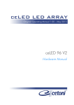
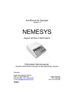
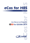
neMESYS
neMESYS
Original User Manual 1.01 - April 2013
User Manual
MAGCHEX valve
cetoni GmbH
Am Wiesenring 6
D- 07554 Korbußen
Tel.: +49 (0) 36602 338-0
Fax: +49 (0) 36602 338-11
E-Mail:
Internet:
[email protected]
www.cetoni.de
1. Preamble
This manual is to support the user in the correct handling and the maintenance
of cetoni's MAGCHEX check valves.
2. Technical Data & Handling
2.1. Wetted Materials
The following sectional view shows the individual components of the
MAGCHEX
check valves. All parts in contact with the fluid are shown with blue identifiers,
those of non-wetted parts with red identifiers. In addition, the table below
details the materials. Please ensure material compatibility with the respective
fluid that is to be used.
2
MAGCHEX User Manual
#
Description
Material
1
inlet housing
PPS GF40 - Polyphenylene sulfide with
2
outlet housing
40% glass fibre
3
sealing disc
magnet, Parylene C-coated
4
flow seal O-ring
FFKM (Perlast G60A)
5
housing seal O-ring
FFKM (Perlast G80A)
6
adjustment screw
[no media contact (magnet)]
2.2. Cracking Pressure Adjustment
The opening or cracking pressure of the
MAGCHEX
is continuously adjustable
between 0.1 and 0.5 bar via the adjustment screw.
Fully tightened, the cracking pressure is the highest. Turn the adjustment screw
counter clockwise to reduce the cracking pressure as required.
The following graph plots the cracking pressure vs. the number of turns of the
adjustment screw relative to the fully-tight position for the use with water and a
flow rate of 5 µl/s:
MAGCHEX User Manual
3
After prolonged time of nonuse, sealing disc and flow seal can stick together and
cause a higher initial opening pressure.
2.3. Maximum Working & Burst Pressures
The maximum working pressure of the
MAGCHEX
check valves is 200 bar, which
may be surpassed temporarily by 50 bar. The burst pressure is 320 bar.
3. Maintenance
After use with aggressive fluids, please thoroughly cleanse the check valve with
distilled water followed by, if possible, drying with compressed air.
If this procedure is not feasible as well as prior to extended periods of nonuse,
you should disassemble and dry the valves. Otherwise, and in particular at tiny
spots with insufficient/imperfect coating of the magnetic sealing disc, corrosion
may occur which may limit the use time of the device.
Disassembly of the valve is also necessary before changing the O-rings or the
sealing disc. To do this, please proceed as follows:
4
MAGCHEX User Manual
3.1. Disassembly
1. Using a screwdriver and turning it counterclockwise, remove the
adjustment screw.
2. Remove the four housing screws using a 2.5 mm hexagon socket (Allen)
key.
3. Now you may remove the inlet housing part, which contains the flow seal
O-ring. In case of the check valve being fixed to a mounting plate, it may
be helpful to loosen the attachment screw first to prevent it from being
jammed.
MAGCHEX User Manual
5
mounting plate
4. Remove the remaining parts for cleaning or exchange.
magnetic sealing disc
outlet housing
housing seal O-ring
flow seal O-ring
inlet housing
6
MAGCHEX User Manual
3.2. Assembly
1. Insert the housing seal into the outlet housing. Place the flow seal O-ring
onto the peg of the inlet housing.
2. Take the sealing disc into one hand and the adjustment screw into the other
hand. As both parts are magnets, they will push apart or pull together,
depending on their respective orientation. Orient the sealing disc such that it
is being pushed away from the adjustment screw. Insert the disc into the
outlet housing whilst maintaining this relative orientation.
IMPORTANT
Please make sure to orient the magnetic sealing disc correctly during
assembly. Otherwise, the valve may not close!
3. Insert the inlet housing and fix it using the four screws. Re-tighten the screw
of the mounting plate.
4. Screw in the adjustment screw to its original position.
MAGCHEX User Manual
7