1
Interconnect schemes for stretchable
array-type microsystems
PROEFSCHRIFT
ter verkrijging van de graad van doctor
aan de Technische Universiteit Delft,
op gezag van de Rector Magnificus Prof. ir. K. C. A. M. Luyben,
voorzitter van het College voor Promoties,
in het openbaar te verdedigen
op woensdag 6 april 2011 om 12.30 uur
door
Sebastian SOSIN
Master of Science Microsystems Engineering,
Universitatea Politehnica Bucureşti,
geboren te Boekarest, Roemenië.
Dit proefschrift is goedgekeurd door de promotor:
Prof. dr. P. M. Sarro
Samenstelling promotiecommissie:
Rector Magnificus, voorzitter
Prof. dr. P. M. Sarro
Dr. M. Bartek
Prof. dr. R. A. M. Wolters
Prof. dr. ir. R. Dekker
Prof. dr. P. J. French
Prof. dr. ir. L. J. Ernst
Prof. dr. J. N. Burghartz
Prof. dr. ir. C. I. M. Beenakker
Technische Universiteit Delft, promotor
Technische Universiteit Delft, copromotor
Universiteit Twente
Technische Universiteit Delft
Technische Universiteit Delft
Technische Universiteit Delft
Universität Stuttgart, Duitsland
Technische Universiteit Delft, reservelid
The research presented in this thesis was financially supported by the Dutch Bsik
program MicroNed and the Delft Centre for Mechatronics and Microsystems (DCMM).
Sebastian Sosin,
Interconnect schemes for stretchable array-type microsystems,
Ph.D. thesis, Delft University of Technology,
with summary in Dutch.
ISBN: 978-90-5335-390-5
Copyright © 2011 by Sebastian Sosin
All rights reserved. No part of the material protected by this copyright notice may be
reproduced or utilized in any form or by any means, electronic or mechanical, including
photocopying, recording or by any information storage and retrieval system, without the
permission of the author.
Printed by Ridderprint BV, Ridderkerk, the Netherlands
Contents
1
Introduction
1.1 Motivation
1.2 Scope of the thesis
1.3 Organization of the thesis
1.4 References
1
1
4
5
6
2
Stretchability of Silicon Based Microsystems
2.1 Definition of stretchability
2.2 Mechanical properties of materials
2.3 Material selection and material data
2.4 State of the art
2.5 System aspects of stretchable silicon microsystems
2.6 Fabrication compatibility, handling and reliability
2.7 Conclusions
2.8 References
7
7
8
14
16
25
26
28
29
3
Stretchable Interconnect Schemes
3.1 Introduction
3.2 General requirements on stretchable interconnects
3.3 Geometry for stretchability
3.3.1 Mesh geometry
3.3.2 Spiral geometry
3.3.3 Meander and horseshoe geometry
3.3.4 Parametric structure description
3.4 Finite-element simulation
3.4.1 Meander interconnects analysis
3.4.2 Horseshoe interconnect analysis
3.4.3 Mesh interconnect analysis
3.4.4 Analysis conclusions
3.5 Mechanical characterization and test set-up used
3.6 High-aspect-ratio-silicon springs
3.6.1 Design and optimization
3.6.2 Fabrication
3.6.3 Characterization results
3.7 Free-standing metal interconnects
3.7.1 Geometry selection
3.7.2 Fabrication
3.7.3 Characterization results
3.7.4 Parylene coating for strength modification
3.8 Conclusions
3.9 References
30
30
30
31
31
32
32
33
35
38
39
40
42
42
44
45
47
50
54
55
56
57
60
64
66
4
PDMS-Embedded Silicon Electronics Arrays
4.1 PDMS-embedded electronics concept
4.1.1 Fabrication process development
4.1.2 Characterization results
4.2 Mesh shape optimization
4.3 Fabrication of PDMS-embedded Si electronics arrays
4.4 Array description
4.5 Measurements
4.5.1 Tensile testing of fabricated arrays
4.5.2 Electrical measurements of fabricated samples
4.5.3 Cyclic tensile testing
4.6 Failure of fabricated PDMS arrays
4.7 Conclusions
4.8 References
67
67
68
72
75
76
77
78
79
80
83
85
88
89
5
Conclusions and Recommendations
5.1 Conclusions
5.2 Recommendations for future work
5.3 References
90
90
92
93
A
Appendix A: High-Aspect-Silicon-Springs Flow Chart
94
B
Appendix B: Free-Standing Copper Interconnects Flow Chart
95
C
Appendix C: PDMS-Embedded Silicon Electronics Arrays Flow
Chart
96
Summary
98
Samenvatting
100
List of Publications
102
Acknowledgements
104
About the Author
106
Chapter 1:
Introduction
1.1. Motivation
From its beginning in the 1950s, microelectronics has been working to
make better, faster and more reliable IC’s. This was quite accurately predicted
by Gordon Moore in 1965 when he stated that the number of transistors that can
be placed on an integrated circuit will increase exponentially, doubling
approximately every two years.
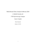
Figure 1-1. The combined need for digital and non-digital functionalities in an
integrated system is translated as a dual trend in the International Technology
Roadmap for Semiconductors: miniaturization of the digital functions (“More Moore”)
and functional diversification (“More-than-Moore”) [1.1].
The microelectronics community is working on finding new solutions to
keep Moore's law alive by miniaturization (an approach called “More Moore”).
Through transistor scaling, one obtains a better performance-to-cost ratio of
products, which drives an exponential growth of the semiconductor market.
This in turn allows for further investments in semiconductor technologies which
will fuel further scaling
1
INTERCONNECT SCHEMES FOR STRETCHABLE ARRAY-TYPE MICROSYSTEMS
The industry is now faced with the increasing importance of a new trend,
“More than Moore” (MtM or better named, “Diversification”, see Figure 1-1),
where added value to devices is provided by incorporating functionalities that
do not necessarily scale according to Moore's law. This research direction deals
with products and technology that are based upon or derived from silicon
technologies, but do not simply scale according to Moore’s law. Typical
examples are RF, power/high-voltage devices, passives, sensors, actuators,
MEMS, bio-chips, bio-systems, microfluidics, system in a package, solid-state
lighting, etc.
Flexible printed circuit boards are being used to fabricate foldable
electronics but the deformation is limited to one axis at a time. In recent years,
many groups have started investigating microelectronic systems that can truly
deform while maintaining their functionality.
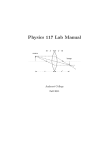
One of the best examples of stretchable electronic systems is the concept of
“artificial skin.” It is supposed to have not only all the sensing capabilities of
our skin but also similar mechanical behavior (Figure 1-2).
Figure 1-2. Artificial electronic skin being developed by Nokia and Cambridge
University [1.2].
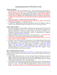
A flexible display such as an e-paper is an important application with
promising demonstrators being presented (Figure 1-3). Having
rollable/bendable screens reduces weight and increases portability. Applications
are in advertising, media, public notice boards, mobile computing, etc.
2
INTRODUCTION
(a)
(b)
Figure 1-3. (a) The LG and Phillips E-ink display [1.3], and (b) the Polymer Vision
(now Wistron) portable e-reader with a 5-inch fold-up display [1.4].
Shapeable and elastic integrated circuits on soft elastomeric substrates are
creating new research opportunities for biomedicine, cell research and medical
prosthetics and implants. Cell culture mediums that have soft substrates with
integrated circuits and stretchable conductors can improve drug testing and invivo tissue research. Smart medical prosthetics can restore human sensory and
motor functions and medical implants that conform to the surrounding tissue
can minimize the patient’s discomfort. Medical implants that conform to the
surrounding tissues by being elastic and flexible can enhance the patients
comfort. Bladder implants for treating incontinency, brain electrodes that treat
epilepsy and depression, fall-detection monitors for the elderly or intelligent
textiles that monitor health conditions are products that can be made better
using stretchable electronics.
For consumer electronics, ambient intelligence is the keyword for the next
decade. This means that a person carries more and more devices, not only on his
body but also inside the body. This affects the way devices are designed: they
must be light weighted, must take on the shape of the object in which they are
integrated, and must even follow complex movements of these objects, hence
the need for stretchability. Shapeable electronics also create a more natural
environment for living tissue research or drug testing, leading to faster
diagnostics or faster drug development.
Smart textiles, biomedical applications, cell research, medical prosthetics,
automotive industry, consumer electronics, displays, all are the domains that
will welcome flexible, stretchable and elastic electronic systems.
3
INTERCONNECT SCHEMES FOR STRETCHABLE ARRAY-TYPE MICROSYSTEMS
1.2. Scope of the thesis
Most of the research done on stretchable systems focuses on hybrid
integration of silicon chips on a pre-fabricated carrier, followed by
encapsulation using molding of a rubber-like compound. Several groups
working on stretchable electronics have reported elongation levels starting from
12-15 % (Lacour, elastically stretchable TFT inverter [1.5]) up to 40-60 %
(polyimide-supported copper interconnects [1.6, 7]). Results from the European
Project STELLA show demonstrators intended for applications enclosing or
attached to the human body (relatively low elongation levels, up to 10 %) like
clothing, smart band aid, shoe insole for diabetes monitoring and activity
monitor [1.8].
The goal of this thesis work is to develop a wafer-level CMOS-compatible
post-processing module that allows transformation of rigid silicon wafers
containing MEMS/CMOS devices into stretchable systems using conventional
clean room equipment. The fabrication process does not, however, exclude the
possibility of hybrid integration of additional chips. This approach based on the
limited silicon wafer size is suitable for applications requiring small-area
stretchable systems like biomedical implants.
Figure 1-4. Illustration of the segmentation method showing (left) monolithic silicon
system die with different functional blocks, and (right) segmented system with
interconnect network embedded in a protective polymer layer.
The selected fabrication approach (Figure 1-4) modifies the initially rigid
silicon substrate by segmenting it into rigid islands connected by an elastic
medium. The elastic medium linking the functional islands must provide
electrical connections between the segments (using flexible metal interconnects)
and mechanical support (using polymers, structured silicon). The focus of this
work is on the stretchable interconnect scheme.
The following chapters present the development process of such a
stretchable system, starting from testing of individual spring-like structures to
the integration of all components into one stretchable silicon-based array.
The interconnect network must be strong enough to withstand tensile
loading without sacrificing electrical performance. For this reason metal layers
4
INTRODUCTION
are selected instead of conductive polymers. While metal layers have limited
elasticity, when patterned for stretchability several geometries (such as mesh,
meander or horse shoe) can withstand large strains.
The processing compatibility with already integrated MEMS/CMOS
devices requires that the post-processing module has adequately low thermal
budget and all of the used fabrication steps will have negligible influence on the
performance of already integrated devices.
The developed post-processing module is applicable on wafer scale,
reducing handling and assembly times, but if needed, hybrid substrates with
chips provided by different technologies could be used without major process
modifications.
Biomedical applications are one of the most promising areas and
biocompatibility should be taken into account when selecting materials and
designing process flow.
1.3. Organization of the thesis
Chapter 1 presents the motivation behind this work, presenting a short
overview of domains where stretchability can increase the performance of
existing products.
In Chapter 2 a concise theory of elasticity and material properties used
throughout the thesis is introduced. Furthermore, an overview of the state of the
art in stretchable electronics research and the fabrication approaches used are
given.
Chapter 3 presents the analysis of different free-standing geometries chosen
for the stretchable interconnect network. The FE simulations are followed by
tensile testing of free-standing High-Aspect-Ratio-Silicon (HARS) springs and
copper meshes. Simulation and tensile testing results are used to design a new
set of metal interconnects.
Chapter 4 starts with the development of the fabrication process for
stretchable silicon electronics arrays. The fabrication process is developed in
steps, starting from fabrication of metal interconnects on polydimethylsiloxane
(PDMS) membranes and ending with the fabrication of a functional stretchable
silicon-based arrays. In the final part of Chapter 4, the results of both
mechanical and electrical testing under single and cyclic tensile loading are
presented.
Chapter 5 ends the thesis by presenting conclusions and recommendations
for future work.
5
INTERCONNECT SCHEMES FOR STRETCHABLE ARRAY-TYPE MICROSYSTEMS
1.4. References
[1.1]
[1.2]
[1.3]
[1.4]
[1.5]
[1.6]
[1.7]
[1.8]
Arden, W., et al., "More-than-Moore" White Paper, 2010, white paper,
International Technology Roadmap for Semiconductors (ITRS).
Stretchable Electronic Skin, Nokia Research Center, Cambridge, UK,
http://research.nokia.com/news/9510, Feb. 2011.
Flexible
Displays,
LG
Display:
Future
Technology,
http://www.lgdisplay.com/, Feb. 2011.
Readius
eBook
reader/cell
phone
prototype
from
Wistron/PolymerVision,
http://wiki.mobileread.com/wiki/Readius,
2010.
Lacour, S.P., Jones, J., Suo, Z., and Wagner, S., Design and
performance of thin metal film interconnects for skin-like electronic
circuits, IEEE Electron Device Letters, 2004, 25(4), pp. 179-181.
Verplancke, R., Sterken, T., Axisa, F., and Vanfleteren, J., Development
of a thin-film stretchable electrical interconnection technology for
biocompatible applications, 3rd Electronic System-Integration
Technology Conference (ESTC), 2010, Berlin, Germany, pp. 1-4.
Axisa, F., Brosteaux, D., De Leersnyder, E., Bossuyt, F., Vanfleteren,
J., Hermans, B., and Puers, R., Biomedical Stretchable Sytems using
MID Based Stretchable Electronics Technology, 29th Annual
International Conference of the IEEE Engineering in Medicine and
Biology Society (EMBS), 2007, Lyon, France, pp. 5687-5690.
European Project, http://www.stella-project.de, Feb. 2011.
6
Chapter 2:
Stretchability of Silicon-Based Microsystems
In the first part of this chapter the theory of material properties used
throughout the thesis for analysis of stretchable electronics is presented. The
theoretical part is followed by an overview of the state of the art in stretchable
electronics with examples of realized stretchable systems. The last part deals
with system aspects, fabrication, handling and reliability of stretchable silicon
microsystems.
2.1. Definition of stretchability
According to Merriam-Webster’s dictionary, the verb “to stretch” is defined
as “a: to enlarge or distend especially by force; b: to extend or expand as if by
physical force.” Stretchable electronics systems must function as designed
while being able to conform onto complex shapes, expand, and contract
reversibly (within certain limits).
This means that a silicon microsystem has to modify its surface area and
shape in order to contract/expand and to preserve its functionality when an
external force is applied. A definition valid for all stretchable electronic system
research approaches is that a stretchable electronic system is made of a number
of rigid or flexible component islands, which are connected by an elastic and
electrically conductive medium.
Figure 2-1. Illustration of the stretchable system concept using rigid islands and
stretchable interconnects/substrate.
7
INTERCONNECT SCHEMES FOR STRETCHABLE ARRAY-TYPE MICROSYSTEMS
2.2. Mechanical properties of materials
The phrase “stretchable silicon array microsystem” can be misleading.
Silicon, the main material in almost all the integrated circuits, is intrinsically
brittle and rigid, when compared to metals or polymers currently used in
microfabrication. Silicon wafers can become flexible by thinning them and
useful degrees of flexibility can be achieved for thicknesses below 50 µm but
large scale elasticity of bulk silicon is impossible to achieve without using some
processing tricks and/or additional materials providing elasticity.
When talking about stretchable systems, terms like stress, strain or Young’s
modulus are used to describe the systems and the materials they are made of.
Explaining these terms, even if briefly, is necessary for understanding of the
following chapters of this thesis [2.1].
In a body, two atoms or molecules are subjected to attraction or repulsion
forces that act along a line joining the two particles. These forces hold together
the body and are called “internal forces.” Similar to Newton’s universal gravity
law, they vary inversely as an exponent of the radial distance that joins the two
particles.
Figure 2-2. Stress in a loaded deformable body.
When the body is subjected to external forces (Figure 2-2), its shape changes
thus changing the distance between internal particles. Therefore internal forces
also change and if their values exceed a certain limit, the body will break apart.
8
STRETCHABILITY OF SILICON-BASED MICROSYSTEMS
The change in the intensity of the internal forces is called stress and
characterizes the strength of a body.
A single particle P of a body is subjected to many forces that can be replaced
by the resulting force that acts on that particle. Depending on the location of the
point, the magnitude and direction of the resulting force will vary, meaning that
when the body is subjected to external forces, an internal force distribution is
generated in the body.
The internal distributed force F on an imaginary surface A through the body
divided by this surface area is called stress on a surface. The force that is
normal to the surface is called the normal stress (σ) on a surface while the force
parallel to the surface is called the shear stress (τ):
σ AVG =
Fn
≈σ
A
τ AVG =
Fs
≈τ
A
(2.1)
(2.2)
Normal stress can be described as internal forces developed as material
resistance to the pulling apart or pushing together of two adjoining planes of
the imaginary surface. Shear stress can be described as internal forces
developed as material resistance to sliding of two adjoining planes along the
imaginary surface
Tensile stress is a normal stress that pulls the surface away from the body
while compressive stress pushes the surface into the body.
In general, stress is not uniformly distributed over the cross-section of a
material body, and consequently the stress at a point in a given region is
different from the average stress over the entire area. Therefore, it is necessary
to define the stress not over a given area but at a specific point in the body
(point “P” in Figure 2-2). According to Cauchy [2.1], the stress at any point in
an object assumed to behave as a continuum is completely defined by the nine
components σij of a second-order tensor known as the Cauchy stress tensor, σ,
where σii and i = j ∈ (x,y,z) represents normal stress components while τij, i≠j,
represents shear stress components (2.3). Shear stress is symmetric, meaning
that τij = τji.
⎡σ xx τ xy τ xz ⎤
[σ ] = ⎢⎢τ yx σ yy τ yz ⎥⎥
⎢ τ zx τ zy σ zz ⎥
⎣
⎦
(2.3)
When a body is subjected to an external force, a change in shape appears.
The measure of this change is called strain. Strain, defined as the ratio between
the change in length δL and the original length L0, can be easily converted into
9
INTERCONNECT SCHEMES FOR STRETCHABLE ARRAY-TYPE MICROSYSTEMS
percentage. Such representation of the strain makes it easier to describe the
stretching effects on an object’s dimensions. As an example, if a 100 cm bar is
stretched to 110 cm, then the strain can be expressed as ε = 10 %.
ε=
and
ε=
L − L0 δL
=
L0
L0
δL
L0
∗100%
(2.4)
(2.5)
The shear strain is defined as the change in angle from the right angle as
shown in Eq. 2.6, where α is the final angle.
γ=
π
2
−α
(2.6)
A material is said to be elastic if it returns to its original, unloaded
dimensions when the load is removed. A particular form of elasticity (which
applies to a wide range of engineering materials, at least over a part of their load
range) produces deformations that are proportional to the loads producing them.
Since loads are proportional to the stresses they produce and deformations are
proportional to the strain, this also implies that, while materials are elastic,
stress is proportional to strain (Eq. 2.7). Hooke’s law, in its simplest form, was
initially stated in 1676 by British physicist Robert Hooke as a Latin anagram,
“Ut tensio, sic vis” meaning “As the extension, so the force.”
stress σ
= = const.
strain ε
(2.7)
Considering a linear material model, where there is a linear relationship
between stress and strain, Hooke’s law can be written as:
⎧ε xx ⎫ ⎡ C11 C12 C13 C14 C15 C16 ⎤ ⎧σ xx ⎫
⎪ε ⎪ ⎢
⎥⎪ ⎪
⎪ yy ⎪ ⎢C21 C22 C23 C24 C25 C26 ⎥ ⎪σ yy ⎪
⎪⎪ε zz ⎪⎪ ⎢C31 C32 C33 C34 C35 C36 ⎥ ⎪⎪σ zz ⎪⎪
⎥ ⎨τ ⎬
⎨γ ⎬ = ⎢
⎪ yz ⎪ ⎢C41 C42 C43 C44 C45 C46 ⎥ ⎪ yz ⎪
⎪γ zx ⎪ ⎢C51 C52 C53 C54 C55 C56 ⎥ ⎪ τ zx ⎪
⎥⎪ ⎪
⎪ ⎪ ⎢
⎪⎩γ xy ⎪⎭ ⎢⎣C61 C62 C63 C64 C65 C66 ⎥⎦ ⎩⎪ τ xy ⎪⎭
(2.8)
The matrix Cij in Eq. 2.8 is called the compliance matrix and it is a
symmetric matrix, Cij = Cji, with i, j ∈ {1..6} . Isotropic materials require only
10
STRETCHABILITY OF SILICON-BASED MICROSYSTEMS
two independent material constants and Hooke’s law for isotropic materials is
defined by Eq. 2.9.
⎧ε xx ⎫ ⎡ C11 C12 C12
0
0
0
⎤ ⎧σ xx ⎫
⎪ε ⎪ ⎢
⎥ ⎪σ ⎪
0
0
0
⎪ yy ⎪ ⎢C12 C11 C12
⎥ ⎪ yy ⎪
⎪⎪ε zz ⎪⎪ ⎢C12 C12 C11
⎥ ⎪⎪σ zz ⎪⎪
0
0
0
⎥⎨ ⎬
⎨γ ⎬ = ⎢
0
0
⎥ ⎪ τ yz ⎪
⎪ yz ⎪ ⎢ 0 0 0 2 ( C11 − C12 )
⎥ ⎪ τ zx ⎪
⎪γ zx ⎪ ⎢ 0 0 0
0
0
2 ( C11 − C12 )
⎥⎪ ⎪
⎪ ⎪ ⎢
2 ( C11 − C12 ) ⎦⎥ ⎩⎪ τ xy ⎪⎭
0
0
⎩⎪γ xy ⎭⎪ ⎣⎢ 0 0 0
(2.9)
Equation 2.9 can be rewritten in equation form using three material
constants (based on the original two): the modulus of elasticity E,
Poisson’s ratio ν and the shear modulus of elasticity G:
1
(2.10)
C11 =
E
C12 = −
ν
(2.11)
E
2 ( C11 − C12 ) =
1
G
(2.12)
Substituting C11 and C12 in the last relationship, the shear modulus of
elasticity is defined:
G=
E
2 (1 +ν )
(2.13)
Poisson’s ratio is a dimensionless measure of the lateral strain that occurs in
a body due to longitudinal strain, if the load on the object is restrained within
the elastic range:
ν=
εd
εL
(2.14)
The negative sign is usually ignored, leaving the coefficient simply as a ratio
of strain magnitudes but it must be remembered that the longitudinal strain
induces a lateral strain of opposite sign.
By rewriting Eq. 2.9 with the previous substitutions, a more simplified
version, called generalized Hooke’s law, valid only for linear, elastic, isotropic
materials is given by equation:
11
INTERCONNECT SCHEMES FOR STRETCHABLE ARRAY-TYPE MICROSYSTEMS
⎧ε xx ⎫
⎡1
⎪ ⎪ 1⎢
⎨ε yy ⎬ = ⎢ −ν
⎪ε ⎪ E ⎢ −ν
⎩ zz ⎭
⎣
−ν
1
−ν
−ν ⎤ ⎧σ xx ⎫
⎪ ⎪
−ν ⎥⎥ ⎨σ yy ⎬
1 ⎦⎥ ⎪⎩σ zz ⎭⎪
(2.15)
The strength of a material can be determined with a tensile test using a “dog
bone”, illustrated in Figure 2-3. The “dog-bone” structure has uniform cross
section and it is subjected to a gradually increasing tensile load until failure
occurs. The length change of the gauge length of the bar is recorded and a graph
is produced. Such a graph is called the tensile stress – strain diagram of the
material (see Figure 2-4).
Figure 2-3. "Dog-bone" structure used for tensile measurements.
Figure 2-4. Typical tensile stress - strain diagram for a ductile material showing
various stages of deformation.
Several points can be identified in a tensile stress-strain diagram, depending
on the material. If the stress in a body subjected to a load returns to zero once
12
STRETCHABILITY OF SILICON-BASED MICROSYSTEMS
the load is removed, then the material of the body is said to have been strained
within the elastic limit or that the material is perfectly elastic. If under loading
the strain is linearly proportional to the load, the material is said to be strained
within the limit of linear elasticity. When the load produces a stress that
exceeds the elastic limit, the strain does not disappear upon the removal of the
load.
Yield strength σYS, (also called elastic limit) is the limit beyond which
permanent deformation will occur.
Under tensile stress plastic deformation is characterized by a strain
hardening region and a necking region and finally, fracture (also called
rupture). During strain hardening the material becomes stronger through the
movement of atomic dislocations. The necking phase is indicated by a reduction
in cross-sectional area of the specimen.
Necking begins after the ultimate tensile strength (σU) is reached. Ultimate
strength is defined as the maximum stress attained in the stress-strain diagram.
During necking, the material can no longer withstand the maximum stress and
the strain in the specimen rapidly increases. Plastic deformation ends with the
fracture of the material.
As it can be observed in Figure 2-4, the plastic range covers a much wider
part of the strain axis than the elastic range. The capacity of a material to allow
these large extensions (i.e., the ability to be drawn plastically) is named
ductility. Materials with high ductility are named ductile materials.
Materials with low ductility are named brittle materials. There is little or no
necking at fracture for brittle materials. Brittle materials such as silicon,
concrete, carbon fiber and polymers such as poly(methyl-methacrylate)
(PMMA) and polystyrene do not have a yield point, and do not strain-harden
(Figure 2-5). Therefore, the yield strength and ultimate strength are the same.
Figure 2-5. Typical stress-strain curve for brittle materials.
13
INTERCONNECT SCHEMES FOR STRETCHABLE ARRAY-TYPE MICROSYSTEMS
2.3. Material selection and material data
Selection of materials has to take into account several factors: mechanical
properties, electrical properties, deposition and patterning methods and IC
fabrication compatibility. Materials used for stretchable silicon arrays can be
divided into three groups. In the first group, there are materials used for the
fabrication of array elements, mainly silicon. Materials used for the stretchable
part of an array form the second group. Silicon can also be part of this group,
along with metals common in IC fabrication like copper and aluminum. The last
group is for materials used as mechanical support and extra protection and it is
composed of polymers such as Parylene, PDMS and photosensitive elastomers.
Silicon, a brittle material, if patterned into very thin foils or beams, can be a
good candidate for the stretchable part of an array. Although not a good
conductor, it can support metal interconnects which have good electrical
conductivity.
Electrical conductivity, deposition methods, IC compatibility and
mechanical properties are factors that limit the options for metal interconnects.
Electrical interconnects between islands are realized using copper or aluminum,
most common metals to the IC industry, with well known deposition and
patterning techniques and good electrical and mechanical properties. Gold is
also used for stretchable interconnects due to its good electrical conductivity
and chemical resistance.
Figure 2-6. Stress-strain curve of an electroplated copper film [2.2].
14
STRETCHABILITY OF SILICON-BASED MICROSYSTEMS
Figure 2-7. Typical stress-strain curve for an evaporated gold film [2.3].
For a stretchable silicon array to function properly, protection against a large
number of external factors is necessary. Protection against humidity, gases,
corrosive chemicals, electrical insulation or just additional mechanical support
can be achieved using polymers. Depending on the design, the array can be
fully embedded in a polymer foil or just coated with an insulating layer, similar
to regular electrical conductors.
Polymers can also be used during fabrication as a temporary mechanical
support layer or just protective coating. PDMS can be spin coated, molded and
casted in a wide range of thicknesses. It provides good mechanical protection
and electrical insulation by fully embedding a system, providing a large
extension interval in the same time.
Figure 2-8. Strain-stress curve for a PDMS foil at room temperature [2.4].
15
INTERCONNECT SCHEMES FOR STRETCHABLE ARRAY-TYPE MICROSYSTEMS
Table 2-1. Material property data of selected materials [2.4, 5].
(Note: The missing data are either not relevant for given combination of the material
property and the material type, or a reliable value was not possible find in the available
literature. The values listed are for bulk material properties and are used to illustrate
the differences between selected materials. Values for thin films depend on deposition
method and can exhibit large variations).
Silicon
Copper
Aluminum
Gold
PDMS
Young’s Modulus
[GPa]
112.4
110
68.0
77.2
0.0017
Yield Strength
[GPa]
0.120
0.262
20
0.240
Ultimate Tensile
Strength [GPa]
0.120
0.310
50
0.302
Bulk Modulus
[GPa]
98.74
140
76
Poisson’s Ratio
0.280
0.343
0.35
0.42
Shear Modulus
[GPa]
43.9
46.0
26
27.2
Electrical
Resistivity [Ω•cm]
-
1.70E-6
2.70E-6
2.20E-6
-
Elongation at Break
[%]
-
-
-
-
174
-
-
-
2.8
Relative Dielectric
Constant
0.5
2.4. State of the art
The methods of producing stretchable silicon electronics can be divided into
two categories [2.6]. Both methods use substrate segmentation to create rigid
functional islands connected by a stretchable and electrically conductive
medium. The first category gets its stretchability by using very thin
semiconductor (brittle) membranes or ribbons that have been compressed using
substrate transfer. In the second category the stretchability is achieved by using
metal layers that are patterned for stretchability and/or polymers that can
accommodate large elongation.
The first approach transforms brittle materials (e.g., single crystalline
silicon) into ultra thin membranes, ribbons or wires. With further processing
and substrate transfer the material becomes “wavy” and the amplitudes and
wavelengths can change according to the applied strain. In plane strains are
accommodated through out-of-plane displacements in the wavy structure.
16
STRETCHABILITY OF SILICON-BASED MICROSYSTEMS
Stretchability is achieved by transferring such a thin network of semiconductor
islands and ribbons to a pre-stretched elastomer substrate. When the elastomer
substrate returns to its relaxed state, semiconductor ribbons form waves (see
Figure 2-9). The first wavy configuration involves continuous intimate
mechanical coupling between the ribbons and elastomer. In the case of silicon
and PDMS, bonding is done by covalent –O-SI-O- linkage that forms due to
condensation reactions between surface –OH groups on the PDMS surface and
the native oxide of the silicon. When formed with the elastomer substrate in a
pre-stretched state, mechanical relaxation creates non-linear buckling or wavy
configurations with amplitudes that depend mainly on the elastic properties of
PDSM and silicon and thickness of silicon.
Figure 2-9. Schematic illustration of ultra-thin ribbon of "wavy” semiconductor
transferred to elastic substrate (a) fully bonded, and (b) partially bonded.
This method has the advantage that the electrical performance and reliability
of such a system are similar to those of wafer-scale electronics and has been
used to create stretchable conductors, diodes and even fully integrated systems
such as an integrated hemispherical electronic eye camera. The method provides
practical levels of stretchability up to 15 %, exceeding by ~15 times the intrinsic
fracture limit of silicon.
The second wavy configuration uses patterned sites of adhesion on the
substrate and/or ribbons to create localized positions of bonding. When the pre
stretched substrate is released, the non bonded regions delaminate from the
substrate. In this case the waviness can be controlled thus controlling the level
of stretchability of the device. With this approach it is possible to achieve
reversible stretching to strains of 100 % or more.
All the research results on stretchable silicon electronics have one thing in
common: silicon has to be patterned, leading to a network with more or less
rigid nodes and flexible/stretchable connexions between nodes.
Silicon wafers can become flexible if thinned to thicknesses under 100 µm.
The thinner the silicon, the more bendable it becomes. This way, products that
rely on unfoldable thin silicon structures have been developed.
17
INTERCONNECT SCHEMES FOR STRETCHABLE ARRAY-TYPE MICROSYSTEMS
Figure 2-10. Stretchable mesh: the square silicon photodetectors, connected by thin
ribbons of metal and polymer, are mounted on a hemisphere-shaped rubber
surface. The entire device is able to conform to any curvilinear shape due to the
flexibility of the ribbons that connect the silicon islands. Credit: Beckman Institute,
University of Illinois.
In 2004, Lacour presented stretchable electrical conductors of 25 nm thick
gold films with surface waves with ~8.4 μm wavelength and ~1.2 μm amplitude
[2.7]. The gold waves showed reproducible and repetitive resistance change and
deformation for a cyclic strain variation for 0 % to 15 %. Using the wavy gold
interconnects, the same group reported the fabrication of an elastically
stretchable TFT circuit (inverter) with identical performances in the relaxed
state and after stretching up to 12 % [2.8]. Amorphous silicon TFTs made on
polyimide foil are mounted face down on contact pads and interconnected with
the stretchable gold conductors. The clear silicone membrane covers the entire
field of view and is partly underlaid by millimeter-ruled paper.
18
STRETCHABILITY OF SILICON-BASED MICROSYSTEMS
Figure 2-11. Photograph of the elastomeric inverter. The circuit is shown in its relaxed
state [2.8].
Using a mesh of silicon photodetectors and very thin wavy metal
interconnects [2.9], a hemispherical electronic eye camera was fabricated by
separating the complex control circuitry from the imager circuitry.
(a)
(b)
Figure 2-12. (a) Photograph of a hemispherical PDMS transfer element with a
compressible focal plane array on its surface and (b) scanning electron microscope
image of a portion of the array in (a), illustrating the compressible interconnects [2.9].
19
INTERCONNECT SCHEMES FOR STRETCHABLE ARRAY-TYPE MICROSYSTEMS
The approach uses wafer-scale optoelectronics formed in unusual, twodimensionally compressible configurations and elastomer transfer elements
capable of transforming the planar layouts in which the systems are initially
fabricated into hemispherical geometries for their final implementation.
Although in this case, the stretchability is exploited only to create fixed 3Dcurved imagers, the concept is valid for systems that modify their shape during
operation. The imager is an array of identical islands with a small number of
inter-island interconnects supported by thin bendable semiconductor bridges.
Figure 2-13. A PCB-mounted hemispherical electronic eye camera [2.9].
The second approach uses meshes constructed from bendable materials to
achieve large and reversible deformation for strains applied on certain axes,
while having functional islands in the nodes of the mesh. In this case in plane
strains are accommodated by in plane rotations, similar to the movement of a
scissors (Figure 2-14). Tensile strains applied at the ends of the structure
transform the rectangles of the mesh into diamond like shapes, the mesh
becoming longer and narrower.
Figure 2-14. Mesh-shaped semiconductor island stretchable system.
Using the mesh topology, conformable, flexible, large-area networks of
pressure and thermal sensors with organic transistor active matrices were
fabricated by the Quantum-Phase Electronics Centre of the University of Tokyo
[2.10]. Arrays of pressure and temperature sensors are built on a film of 75 µm
20
STRETCHABILITY OF SILICON-BASED MICROSYSTEMS
thick polyimide or poly (ethylenenaphtalate) (PEN). Stretchability is obtained
by using a laser to pattern the film in a mesh-like pattern having nodes
containing active IC’s, resulting in a system with 25 % stretchability.
Figure 2-15. A conformable network of pressure sensors. (A) A plastic film with
organic transistors and pressure-sensitive rubber is processed mechanically to form a
unique mesh-shaped structure; (B and C) Circuit diagram of the pressure sensor
network (B) together with a picture of the 3x3 sensor cells (C); (D) Microscope image
of an organic transistor before shaping the net or integrating it with sensors. Dotted
line indicates the semiconductor channel layer. (Scale bar: 1 mm.) [2.10].
Robust polymer meshes are fabricated using metal patterns both as
functional interconnect layers and as in situ masks [2.11]. The method uses laser
ablation to pattern polymer layers into rectilinear and meandering designs with
single or multilayer metal interconnects.
Fabricated structures can be stretched uniaxially up to 50 % while
maintaining good electrical conductivity and structural integrity. “Meandering”
interconnects are observed to have a maximum stretchability of greater than
50 % with a change in resistivity of only 5 %. Redundant interconnect mesh
have a maximum stretchability of almost 30 % (redundant designs will increase
the robustness and viability of interconnects without sacrificing stretchability).
A 40 mm by 40 mm interconnect mesh prototype using the redundant mesh
design was fabricated as a proof of concept for feasibility of the developed
process.
21
INTERCONNECT SCHEMES FOR STRETCHABLE ARRAY-TYPE MICROSYSTEMS
Figure 2-16. Interconnect mesh concept for rectilinear, “meandering,” and redundant
“meandering” interconnects. The interconnects consist of a polymer substrate and two
metal layers separated by a spin-on polyimide dielectric layer [2.11].
(a)
(b)
(c)
(d)
Figure 2-17. (a) Meandering interconnect design with 10 line-width; (b) and (c)
Redundant interconnect designs with 40 µm line-width; (d) Demonstration of flexibility
of 40 mm by 40 mm redundant sensor mesh (conformability to a spherical flask with
diameter of 50 mm) [2.11].
22
STRETCHABILITY OF SILICON-BASED MICROSYSTEMS
Several stretchable electronics products (for sensor applications for medical
electronics and textile electronics) have been developed in the frame of the
European project STELLA [2.12]. PCB quality copper sheets (17-70 μm thick)
are laminated on thermoplastic polyurethane (TPU) foils (100 μm thick).
Following the lamination process, the copper foil is patterned into meanders to
define stretchable interconnects. Additional “stiffening” structures are
fabricated in the copper patterning step. Their role is to locally prevent substrate
stretching, being able to protect the interconnections up to very high elongations
(500 % tested). Additional components are assembled (manually or using
automated pick & place machine) and soldered to the substrate using low
temperature reflow (165 °C). The final encapsulation is done using a cast
overmolding process. The profile of the encapsulation is such that the transition
between the thick encapsulation and the thinner part containing only the
stretchable lines is smoothed out.
Figure 2-18. Close-up of stiffening structure around a compnent position [2.12].
One of the products fabricated with this technology is a band aid equipped
with pressure sensors and a simple humidity sensor. Pressure sensors are used
for monitoring of the pressure on the wound during compression therapy. Data
is read out wireless using inductive data transmission with a reach of ~ 1 m
from the antenna. Rather large holes in the polyurethane were included for
permeability of air and humidity in order to improve user comfort.
Figure 2-19. Band aid demonstrator [2.12].
A second product is a three point pressure sensor for integration into a shoe
insole. Most of the systems are wires only connecting the three sensors which
23
INTERCONNECT SCHEMES FOR STRETCHABLE ARRAY-TYPE MICROSYSTEMS
are located at the heel, the ball of the first and the fifth toe, respectively. In
order to provide as much as possible user comfort by allowing circulation of air
and moisture, most of the polyurethane surrounding the wires connecting the
three sensors was eliminated. However, in order to be easy to handle the
remaining structure was laminated into a highly permeable non-woven fabric.
Textile industry already uses polyurethanes for various applications such as
glue to join textiles, as ultra thin layer acting being a semi permeable membrane
in waterproof textiles, or as interlining separating different layers of cloths from
each other. The connection of polyurethanes is a lamination process operated at
similar temperatures as ironing. An example of a stretchable electronic system
containing acceleration sensors, processors and LEDs was designed and
laminated onto a commercial fabric to be integrated into a shirt, see Figure 2-20.
A high robustness in many wear cycles has been field proven with this
application.
Figure 2-20. Stretchable electronic system laminated to fabrics [2.12]
Since the islands can only bend (if thin enough), the stretching part has to be
done by the materials between the islands. Conductive and non conductive
polymers, silicone rubbers and metals are some of the choices. These materials
have to support the islands, provide electrical connections between the islands
and stretch. When looking for the right combination of materials, one has to
take into account processing compatibility and properties of individual
materials, such as conductivity, elasticity, bio-compatibility, reactivity to
chemicals and so on.
Although the goal of stretchable electronics research is to develop systems
that can uniformly stretch, changing their dimensions by hundreds of percents,
current materials properties (both mechanical and electrical) limit the design
and fabrication choices.
While the functional blocks of a stretchable electronic systems are fabricated
on a rigid substrate with limited flexibility, the materials used for interconnects
and protection are more stretchable. This is why the focus of stretchable
electronics is on the stretchability of interconnects and protective polymers
while leaving the circuitry largely unchanged on rigid substrates.
24
STRETCHABILITY OF SILICON-BASED MICROSYSTEMS
2.5. System aspects of stretchable silicon microsystems
Traditional chips can have hundreds, even thousands of interconnects. When
a system is segmented into functional blocks, two types of interconnects are
noticed: interconnects between blocks and interconnects on individual blocks.
By rethinking the system for this approach and dividing it into small enough
blocks but keeping the number of inter-block interconnects to a minimum, more
complex systems can be made stretchable. While in some cases, it is necessary
to make the whole system stretchable, in some applications only a part of the
segmented system will be stretchable this way minimizing the number of
needed stretchable interconnects.
Polymers can be stretched by hundreds of percents before they break but
metals have much more limited stretchability. Current research on stretchable
metal interconnect schemes shows that metal interconnects stretchability can be
increased several times by replacing narrow straight metal lines with more
complex shapes such as horseshoe, meanders or meshes.
Using these shapes for metal interconnects can increase stretchability up to
several hundred percents but with serious increase of area used by
interconnects. One simple line can become stretchable if it is replaced with a
meander but the area occupied is several times larger. This limits the number of
interconnects thus limiting the complexity of a stretchable microsystem.
Scaling down the interconnect size by using finer lithography can reduce the
area but also some other issues have to be taken into account. Work done in the
STELLA project shows how discrete components are assembled to a stretchable
printed circuit board (SCB). Two techniques are used to minimize the stress on
components interconnects: local stiffener structures and polyurethane glob tops
with gradually increasing thickness [2.13].
The transition between stretchable (meandering Cu) and rigid parts of the
system (once the components are assembled) has to be accounted for. Stiffening
of the substrate around components is done to protect the component
interconnections against stress due to stretching (Figure 2-18).
(a)
(b)
Figure 2-21. (a) Encapsulated component with a smooth glob top encapsulation, and
(b) fabricated system using polyurethane encapsulation [2.13].
25
INTERCONNECT SCHEMES FOR STRETCHABLE ARRAY-TYPE MICROSYSTEMS
The profile of the glob top encapsulation is such that the transition between
the thick, rather stiff encapsulant and the thinner part containing only the
stretchable copper lines is smoothed out (Figure 2-21a).
By using a combination of these stress reducing techniques, complex
systems can be created and lamination into textiles has been demonstrated
(Figure 2-21b).
2.6. Fabrication compatibility, handling and reliability
Although there is a large variety of materials that can be used, IC fabrication
has strict requirements on chemicals purity, air quality, contaminants and safety.
When selecting materials for interconnects (usually metals) or for protection
(usually polymers), all the IC fabrication contamination and safety requirements
have to be met and processing compatibility of all materials has to be
guaranteed.
Once the materials are selected and fabrication process compatibility and
contamination issues solved, traditional processing and handling steps can prove
to be too aggressive for stretchable systems. A simple example: 20 µm thin
chips connected with thin metal lines embedded in a soft polymer layer can be
tricky to handle during or even after fabrication.
Thin wafers and chips need different handling procedures than traditional
thick ones. Wafer dicing uses high pressure water and adhesive foils that can be
destructive for some flexible systems.
While regular electronic systems are encapsulated in rigid packages that can
be easily handled and connected to circuit boards, new handling and connecting
methods have to be developed for stretchable electronics.
Although the goal is to fabricate systems that can sustain large deformation
without loosing their functionality, substrate transfer is a common technique to
provide the to-be-stretchable systems with enough stiffness needed for
traditional IC fabrication and assembly processes. For fabricating diamond like
carbon (DLC) islands for stretchable electronics, PDMS foils are mounted on
plastic foils for handling during processing and released at the end. A temporary
substrate is also employed in the fabrication process for stretchable printed
circuit boards, part of STELLA project.
Large area electronics arrays of islands connected with narrow spirals using
monolithic silicon use large blocks of silicon needed to handle individual arrays
[2.14].
26
STRETCHABILITY OF SILICON-BASED MICROSYSTEMS
Figure 2-22. Silicon island array using narrow spirals as interconnect (left), showing
large blocks needed for handling (right)[2.14].
Spherical camera lenses are first fabricated on rigid substrates using
established processing techniques. Transfer to a spherical lens is done in several
steps. First, a hemispherical curved PDMS carrier is stretched to a planar shape
and then the silicon island array is transferred using van der Waals forces to
bond the silicon to the pre-stretched PDMS carrier. In the second stage, the pre
stretched PDMS carrier is allowed to return to its relaxed hemispherical shape.
In the last step, the silicon array is bonded using glue to the hemispherical lens.
Figure 2-23. Part of hemispherical camera lens fabrication sequence, illustrating
transfer to curved surface stages [2.9].
In current research there are two generic approaches used for fabricating
stretchable systems, each having its benefits and disadvantages. In the first
approach, the substrate is attached to a flexible/stretchable layer, patterned and
then stretched. The method is wasteful as in order to create stretchable regions
between rigid islands, most of the wafer is removed, leaving only islands
attached to the flexible layer. Another problem appears when one island (die) is
defective and the whole system becomes unusable. Same problem (even more
wasteful) appears if several wafers are bonded and good devices will be
introduced in already defective systems. Depending on the fabrication process,
the wafer can be processed until the end using standard clean room
27
INTERCONNECT SCHEMES FOR STRETCHABLE ARRAY-TYPE MICROSYSTEMS
equipment/techniques, without the need to develop new methods for
handling/processing.
In the second approach, the substrate is patterned, stretched and then, if
necessary, attached to the flexible medium [2.11, 14]. The method suffers from
the same yield problem as the previous (one bad die ruining the whole system)
and a possible additional problem caused by handling and stretching fragile
patterned structures.
A variation of the first approach is hybrid integration (using a dummy
substrate or a functional substrate). It can solve the handling problems by using
established pick-and-place technology to assemble any die configuration on a
target substrate (removed or patterned later), increasing the yield by using
known good dies. Most research examples previously presented use hybrid
integration on a temporary carrier [2.12, 13].
2.7. Conclusions
This chapter presented a theoretical overview of mechanical notions used
throughout the thesis to describe the behavior of stretchable electronic systems.
Current methods of creating stretchable systems have been described and each
fabrication method has been illustrated with relevant state of the art devices.
The performances of current devices were presented along with design,
fabrication and handling issues specific for stretchable systems. Next chapters
will present in detail the selected interconnect geometries, development of
wafer-level fabrication process of stretchable silicon electronics embedded in
PDMS and testing of the fabricated arrays.
28
STRETCHABILITY OF SILICON-BASED MICROSYSTEMS
2.8. References
[2.1]
[2.2]
[2.3]
[2.4]
[2.5]
[2.6]
[2.7]
[2.8]
[2.9]
[2.10]
[2.11]
[2.12]
[2.13]
[2.14]
Vable, M., Intermediate Mechanics of Materials, Oxford University
Press, 2008
Xiang, Y., Tsui, T.Y., and Vlassak, J.J., The mechanical properties of
freestanding electroplated Cu thin films, Journal of Material Research,
2006, 21(6), pp. 1607 - 1618
Vinci, R.P. and Vlassak, J.J. (2006) Mechanical Behavior of Thin
Films, Annual Review of Materials Science 26, 431-462.
Wang, L., Mechanical characterization of flexible and stretchable
electronic substrates, PhD thesis, Delft University of Technology, 2010
MatWeb, Material Property Data, http://www.matweb.com/, Feb. 2011.
Kim, D.H. and Rogers, J.A., Stretchable Electronics: Materials
Strategies and Devices, Advanced Materials Journal, 2008, 20(24), pp.
4887-4892.
Lacour, S.P., Jones, J., Suo, Z., and Wagner, S., Design and
performance of thin metal film interconnects for skin-like electronic
circuits, IEEE Electron Device Letters, 2004, 25(4), pp. 179-181.
Lacour, S.P., Tsay, C., and Wagner, S., An elastically stretchable TFT
circuit, IEEE Electron Device Letters, 2004, 25(12), pp. 792-794.
Ko, H.C., Stoykovich, M.P., Song, J., Malyarchuk, V., Choi, W.M., Yu,
C.J., Geddes, J.B., Xiao, J., Wang, S., Huang, Y., and Rogers, J.A., A
hemispherical electronic eye camera based on compressible silicon
optoelectronics, Nature, 2008, 454(7205), pp. 748-753.
Someya, T., Kato, Y., Sekitani, T., Iba, S., Noguchi, Y., Murase, Y.,
Kawaguchi, H., and Sakurai, T., Conformable, flexible, large-area
networks of pressure and thermal sensors with organic transistor active
matrixes, PNAS, 2005, 102(35), pp. 12321-12325.
Lin, K.L., Chae, J., and Jain, K., Design and Fabrication of LargeArea, Redundant, Stretchable Interconnect Meshes Using Excimer
Laser Photoablation and In Situ Masking, IEEE Transactions on
Advanced Packaging, 2010, 33(3), pp. 592-601.
Loher, T., Seckel, M., Vieroth, R., Dils, C., Kallmayer, C., Ostmann,
A., Aschenbrenner, R., and Reichl, H., Stretchable electronic systems:
Realization and applications, 11th Electronics Packaging Technology
Conference (EPTC), 2009, Singapore, pp. 893-898.
Gonzalez, M., Axisa, F., Vanden Bulcke, M., Brosteaux, D.,
Vandevelde, B., and Vanfleteren, J., Design of Metal Interconnects for
Stretchable Electronic Circuits using Finite Element Analysis,
EuroSime, 2007, London, UK, pp. 1 – 6.
Dinyari, R., Huang, K., Lanzara, R., Kim, G.J.Y., Feng, J., Vancura, C.,
Chang, F.K., and Peumans, P., An Approach to Cost-Effective, Robust,
Large-Area Electronics using Monolithic Silicon, IEDM, 2007,
Washington, DC, USA, pp. 217-220.
29
Chapter 3:
Stretchable Interconnect Schemes
In this chapter the interconnect schemes and geometries selected for the
fabrication of stretchable interconnects are presented. First the general
requirements on a stretchable interconnect are defined and suitable interconnect
geometries are selected. These are then analyzed using finite-element simulation
tools and the obtained results are used for further optimization. In the final part
of this chapter, the fabrication and measurement results obtained for freestanding high-aspect-ratio silicon springs and free-standing stretchable metal
interconnects are presented.
3.1. Introduction
A stretchable silicon microsystem fabricated using a segmented substrate
approach will get its stretchability from two sources: the interconnect between
segments and the protective polymer. The stretchability of the interconnect
depends on two factors: the material and the geometry. The choice of materials
is limited to metals or conductive polymers. There are advantages and
disadvantages of each material as metals have high electrical conductivity but
are elastic for only a rather small tensile strain region, while conductive
polymers have comparably poor electrical performances but much more
favorable elastic properties.
3.2. General requirements on stretchable interconnects
The first question one can ask about a stretchable interconnect scheme is
“How much can it stretch?”. This can be described as the most obvious
requirement of a stretchable interconnect and of a stretchable electronic system.
The strain, as presented in Chapter 2, is defined as the ratio between the change
in length δL and the original length L.
Depending on the final product requirements, the stretching can be
reversible or not. Non-reversible stretching can be useful if the system is
designed to cover a large area but it is fabricated in a folded state and finally
unfolded to its final size. Reversible stretching is more difficult to achieve for
large strain values and fatigue becomes an important failure factor.
Besides the ability to accommodate strains, there are more factors that
influence the performance of a stretchable electronic system. All stretchable
electronic approaches use lateral segmentation of the substrate, i.e., rigid
functional nodes connected by an elastic and electrically conductive medium.
The nodes or islands must be supported by the surrounding elastic and
conductive network. Depending on the fabrication methods and materials,
30
STRETCHABLE INTERCONNECT SCHEMES
mechanical support can be provided by interconnects only (if strong enough), or
achieved by application of soft and elastic polymers. The latter being a more
frequent choice. In addition to the mechanical support, the polymers can also
provide mechanical and/or chemical protection.
In a traditional monolithic chip, the role of interconnects is to carry signals
between the different components with minimum losses. When compared to
traditional monolithic chips, stretchable systems use a larger area as the chip is
divided into functional blocks linked with a stretchable and conductive medium.
In a stretchable system, besides carrying electrical signals between individual
blocks, interconnects (together with the surrounding supporting medium) must
stretch to withstand strain. The interconnect geometry determines its ability to
stretch but also determines the electrical resistance. The change of electrical
resistance with changing strain must be taken into account when selecting a
certain shape and size for the interconnect network as it can seriously affect the
system performance.
Depending on the application, a stretchable system might need to stretch
more in one direction but nevertheless 2D stretchability is desired. 1D stretching
is a (relatively) simple case as all the interconnect designs presented can be
stretched mainly in one direction (longitudinal) but can also withstand small
transversal deformation.
For 2D stretching, there are two cases that can be considered. A simple
solution is to use interconnects with 1D stretching ability, distributed along the
main stretching axes, obtaining in this way a system that can globally stretch in
2D. Such a system will have limited 2D stretchability as interconnects still have
a preferred axis of deformation. Another approach is to use an interconnect
shape that can stretch in 2D because of its design. A mesh geometry, similar to
woven textiles, is an example of such design.
3.3. Geometry for stretchability
Elastic deformation in metals is limited to very small strains. Patterning
metals into various shapes gives them the ability to deform elastically, thus
recovering their original shape without sustaining damage. Patterned metal
tracks can also be supported by silicon geometries patterned for stretchability.
The geometries discussed next can be used either way, only as thin metal tracks
or as silicon structures supporting the thin metallization.
3.3.1. Mesh geometry
One such pattern is the mesh, consisting of a network of metal beams in a
repeated pattern. Although there can be different geometries for a mesh, such as
honeycomb, rectangular or diamond like, the effect of tensile strains applied at
the ends of the mesh is the same: the elements of the mesh change their shape,
in plane strains are accommodated by in plane rotations, similar to the
movement of a scissors as the mesh becomes longer and narrower.
31
INTERCONNECT SCHEMES FOR STRETCHABLE ARRAY-TYPE MICROSYSTEMS
Figure 3-1. Different mesh designs: honeycomb (left) and rectangular (right).
Such interconnect has some advantages (it is strong and if some parts are
damaged, electrical conductivity is maintained), but its size will greatly limit the
number of interconnects that can be realized on a given area. The mesh shape is
more suitable for unsupported interconnects as the brittle supporting silicon will
greatly reduce the maximum elongation achievable when using only metals.
3.3.2. Spiral geometry
Two spirals, with opposite rotation directions and connected in the middle
(Figure 3-2), can unfold when the ends are pulled apart. Similar to the mesh,
islands can be connected with spiral springs or can be fabricated in the centre of
the two spirals, acting also as connector between the spirals.
Figure 3-2. Spiral design, showing opposite spirals.
The spiral geometry must rotate to unfold and its ability to unwind will be
greatly limited if used as patterned metal embedded in a protective medium. As
supporting silicon structure, the width of the arms must be small (<1 μm) to
allow the arms to unfold to almost a straight line [3.1].
3.3.3. Meander and horseshoe geometry
Other patterns that have been investigated are meander and horseshoe. The
meander pattern is made of a series of half circles (round caps) connected with
vertical straight segments. The transition between the rounded cap and the
straight segment can also have a certain curvature that reduces the stress
concentration in that area, allowing for a higher deformation. If made from a
ductile material, the meander can be stretched to a straight line.
32
STRETCHABLE INTERCONNECT SCHEMES
The horseshoe interconnect is very similar to the meander design. It is made
of half circle segments with optional smaller segments of opposite curvature
that reduce the stress concentration, allowing larger extensions.
Figure 3-3. Meander designs showing simple design (left) and design with additional
curved segments (light grey) (right).
Figure 3-4. Horseshoe designs showing simple design (top) and design with additional
curved segments (light grey) (bottom).
These geometries can be easily tuned to support large longitudinal
deformation by adjusting the curvature angle of the transition segment. Small
size allows large number of interconnects to be used in a system. The meander
version uses more area and is suitable to be used as silicon supporting structure
as the vertical beams allow larger deformation for a certain strain level when
compared to the horseshoe geometry.
3.3.4. Parametric structure description
Each of the structures presented is fabricated by repeating a simple element
(base element) in 1D or 2D. The base element is defined by a set of geometric
parameters, independent of material and processing parameters.
For the rectangular mesh, the base element is defined by four parameters:
• the width of the metal line, W;
• the width of one element, D;
• the length of the vertical lines, L;
• distance between two elements, d.
33
INTERCONNECT SCHEMES FOR STRETCHABLE ARRAY-TYPE MICROSYSTEMS
Figure 3-5. Mesh base element with parameters.
Starting from this simple design, more complex meshes can be created that
have lines with variable width and curved transitions instead of sharp corners.
Meander interconnects are determined by four parameters:
• the width of the metal line, W;
• the radius of the curved element, R;
• the length of the vertical lines, L;
• the angle of the additional curved element, α.
Figure 3-6. Meander curved part (left) and meander (right) with parameters.
The horseshoe design is a simplified version of the meander, without the
vertical lines. Taking this into account, the horseshoe is determined by the three
parameters:
• the width of the metal line, W;
• the radius of the curved element, R;
• the angle of the additional curved element, α.
34
STRETCHABLE INTERCONNECT SCHEMES
Figure 3-7. Horseshoe interconnect geometry with design parameters.
3.4. Finite-element simulations
When constructing an interconnect scheme for a stretchable system, factors
such as overall dimension of the system, number and size of interconnects or
biocompatibility limit the number of design and fabrication alternatives. Area
available for interconnects, total length (increased electrical resistance),
maximum elongation and stress (leading to mechanical failure) are the primary
factors that have to be considered while selecting a certain interconnect.
Chapter 2 presented an overview of the selected materials and their
mechanical and electrical properties. The equations presented are useful when
discussing homogeneous materials but current state-of-the-art systems are all
heterogeneous. The behavior of heterogeneous systems requires numerical
analysis such as finite element simulations.
Tensile load simulations were performed to understand the failure causes
and to optimize the system for increased elongation and lifetime. Because of the
better electrical and mechanical performance but also chemical resistance,
copper interconnections are chosen. Several geometries of spring–like structures
are numerically tested. For the simulations adequate material parameters are
necessary, which were discussed in Chapter 2. The large ratio of width (or
length) to thickness offered a challenge to reliable FE simulation. Therefore
multilevel FEM simulations were performed. A global-local model has the
advantage of subdividing large models into multiple, moderate-size models and
thus separating fixed model parts from parts of the model that may undergo
design changes [3.2].
When exploring the suitability of the new designs to survive large
extensions, the limiting factor for failure is assumed to be the ultimate
equivalent strain in the copper.
As all interconnects are made up from repetition of basic shapes and based
on symmetry considerations, FE simulations can be restricted to the basic
shapes only (Figure 3-5, Figure 3-6 and Figure 3-7). The models used are
illustrated in Figure 3-8. The boundary conditions include fixed x-direction
35
INTERCONNECT SCHEMES FOR STRETCHABLE ARRAY-TYPE MICROSYSTEMS
displacement of nodes at the left end and prescribed x-direction displacements
on all boundary nodes at the right end. The rigid body movements are
additionally suppressed [3.3].
The elastic plastic model for copper has been used [3.4] and material
properties are listed in Table 3-2. Experiments were not performed to establish
the real elasto-plastic properties of the copper interconnect. Instead an elastoplastic behavior is assumed in the present simulations on the basis of
measurement results as published by Dao for a copper line of a thicknesses only
a few microns [3.5]. The actual stress-strain curve as given by Dao is shown as
the dashed line in Figure 3-9. The Young’s modulus and Poisson’s ratio (in the
elastic region) are 128 GPa and 0.36, respectively. As the elasto-plastic
behavior is strongly dependent on the grain size, it is obvious that Dao’s stress
strain curve can only be considered as a rough indication for the real material
behavior of our interconnects. Therefore, the stress strain curve used is a
simplified version using a linear hardening slope and steady plastic behavior
after reaching the ultimate strength (see Figure 3-9). The ultimate strain
according to Dao’s measurements is 11.6 %. In the FE simulation results,
reaching this ultimate strain value is used as a failure criterion, although when
this just occurs locally, the whole structure is not really failed and electrical
conduction will hardly be affected.
Figure 3-8. FE models of free-standing interconnect base parts: (a) meander, (b)
horseshoe, and (c) mesh.
The behavior of a sample under tensile stress can be described by using three
intervals defined by the yield and ultimate strengths (YS and US). For stress
values in the interval [0, YS], the sample gets no damage, only elastic
36
STRETCHABLE INTERCONNECT SCHEMES
MPa
deformation (100 % reversible deformation). In the second interval [YS, US]
samples will not get damaged if extended but will not be able to completely
return to the original shape (combination of elastic and plastic deformation).
The last interval is [US, ∞] where samples will suffer only plastic deformation
(0 % reversible deformation), will get damaged and finally break.
310
262
0.67%
11.6%
Figure 3-9. Stress-strain curve of copper film, dotted line is measurement results
according to [3.5]. Solid line is constructed bi-linear behavior as used in the FE
simulations.
Table 3-1. Interconnect parameters.
Meander and Horseshoe
Parameter
Angle α
Values (µm)
0
15
30
45
Width W
5
10
20
Radius R
10
50
100
Length L (meander)
250
Mesh
Values (µm)
Width W
5
10
20
Distances D, d
5
10
20
Length L
100
300
500
Table 3-2. Material properties of copper used in simulations.
Young’s modulus
128 GPa
Poisson's ratio
0.36
Yield strength
262 MPa
Ultimate strength
310 MPa
37
INTERCONNECT SCHEMES FOR STRETCHABLE ARRAY-TYPE MICROSYSTEMS
3.4.1. Meander interconnects analysis
For meander base elements, defined by (W, L, R, α) (see Figure 3-6),
simulations are performed for elongation steps increasing with 5 % up to a
maximum elongation of 1500 %. The maximum equivalent strain on the
interconnects under the applied elongation steps is determined and by
comparing it with the failure strain (ultimate strain) it is possible to find the
sample elongation (or mean strain level) at (assumed) onset of failure.
The mean strain at onset of failure (defined here as reaching the ultimate
strain of the copper) is presented in Figure 3-10 for various model parameter
sets (width W, radius R and angle α). It is found that the behavior improves with
larger radius R and smaller width W. Also the increase of the angle α has a
positive influence. The best result (being the one with the highest mean strain)
is found for W=5 μm, R=100 μm and α=30°.
Figure 3-10. The mean strain at onset of failure of the meander shape interconnect for
various model parameter sets.
Figure 3-11 shows the equivalent strain distribution at an elongation of
176 % (maximum strain for PDMS) for the meander interconnect with the best
results (W=5 μm, R=100 μm and α=30°) and at the maximum strain before
reaching ultimate strength. The maximum equivalent strains of the free-standing
meander interconnects are found within the area of the wave peak (at the inner
38
STRETCHABLE INTERCONNECT SCHEMES
side). A combination of tensile force and bending moment in the interconnect
line is responsible.
(a)
(b)
Figure 3-11. Equivalent stress distributions for meander interconnect (W, R, α) = (5,
100, 30) at (a) 176 % and (b) 1375 % strain.
Since the strain in a metal beam is inversely proportional to its width, if the
same curvature is used, the elongation can be increased by using narrower metal
lines [3.6].
3.4.2. Horseshoe interconnect analysis
For horseshoe interconnect base elements, simulations are performed for
elongation steps increasing with 5 % up to a maximum elongation of 300 %.
The maximum equivalent strain of the free-standing horseshoe interconnect is
found within the area of the wave peak (at the inner side, see Figure 3-12).
Figure 3-12. Equivalent strain distribution for the horseshoe interconnect (W, R, α) =
(10, 50, 45) under prescribed mean deformation (elongation) of 20 %.
A combination of tensile force and bending moment in the interconnect line
is responsible for this behavior. It is found that the behavior improves with
larger radius R and smaller width W. Increasing the radius leads to a small
39
INTERCONNECT SCHEMES FOR STRETCHABLE ARRAY-TYPE MICROSYSTEMS
increase of the elongation (several percent) but the overall growth of the
structure is much larger, leading to an inefficient use of available area for
interconnects. Also the increase of the angle α has a positive influence. The
maximum mean strain of the sample can reach 250 % for the parameter set
W=5 μm, R=100 μm and α=45°.
Figure 3-13. The mean strain at onset of failure for horseshoe interconnects, for
various model parameter sets (width W, radius R and angle α).
3.4.3. Mesh interconnect analysis
Mesh type interconnects simulations are performed for elongation steps
increasing with 5 % up to a maximum elongation of 500 %. The local maximum
equivalent strain of the free-standing mesh interconnect is found at the inner
side of the vertices (Figure 3-14). A combination of tensile force and bending
moment is responsible for this maximum equivalent strain.
40
STRETCHABLE INTERCONNECT SCHEMES
Figure 3-14. Equivalent strain distribution for the mesh interconnect with (W, D, L) =
(20, 20, 500) under prescribed mean deformation (elongation) of 20 %.
For the mesh shaped interconnects, the mean strain at onset of failure for
various model parameter sets (width W, length L and distance D) is presented in
Figure 3-15. It is found that the behavior improves with larger length R and
smaller width W. Also the increase of the distance D has a positive influence.
The maximum mean strain of the sample can reach 450 % for the meshed
interconnect with beam length L=500 μm, width W=5 μm and distance D=5 μm.
Figure 3-15. The mean strain at onset of failure of the mesh shape interconnects, for
various model parameter sets (beam length L, width W and distance D).
41
INTERCONNECT SCHEMES FOR STRETCHABLE ARRAY-TYPE MICROSYSTEMS
3.4.4. Analysis conclusions
Three types of the interconnects, meander-shaped, horseshoe shaped and
meshed shaped, were designed with various parameter sets. Simulations for the
basic parts were performed to evaluate the influence of the geometric
parameters on the flexibility and stretchability. The free-standing interconnect
shapes and their geometric parameters have significant influence on the
stretchability.
From the three types of interconnects being considered, the meander-shaped
design appears to be most favourable. Because of the enormous flexibility of the
meander-shaped interconnect design, the maximum mean strain of the substrate
(PDMS embedding the coper interconnects) is limited by the maximum mean
strain that other parts can withstand. The maximum mean strain of the rubber
sheets is limited to about 176 %, or less. Therefore the behaviour of the
interconnect up to about 176 % mean strain is considered as quite interesting.
For the most favourable case (W=5 μm, R=100 μm and α=30°), the established
equivalent strain for this mean elongation is found to be 6.439x10⁻³ only. This is
below the elastic strain limit of the copper. As a result, the meander
interconnect (W=5 μm, R=100 μm and α=30° ) will behave fully elastic and thus
will not be damaged, even not under cyclic elongation.
3.5. Mechanical characterization and test set-up used
Mechanical testing of stretchable samples is done using a tensile testing
setup, custom designed and built for easy visual inspection of the sample during
tensile testing. The setup has small form factor and samples can be easily
clamped.
Figure 3-16. Photograph of the testing setup and microscope lens.
The tensile test setup includes clamper, loading part, force sensor,
displacement sensor and data recorder. Force and displacement signals are
42
STRETCHABLE INTERCONNECT SCHEMES
converted by the force sensor and displacement gauge, amplified by the HBM
KWS amplifier, changed into digital signal by A/D converter and finally
recorded by a LabView virtual interface. The software can record the data when
a key is pressed (manual mode, allowing investigation of samples with the
microscope) or in automated mode (one measurement each second).
Figure 3-17. Diagram showing tensile setup components.
Clamping of the stretchable samples is done using two aluminum plates
attached to the tensile setup with screws and the displacement is controlled by a
micro screw attached to the clamper. A diagram of the tensile setup clamping
parts is shown in Figure 3-18.
Figure 3-18. Tensile setup sample clamping diagram.
After the raw data file is processed, the measurement data is displayed as a
graph showing displacement versus tensile load. Figure 3-19 shows the typical
response of a rectangular copper mesh interconnect (elongation, strain vs.
force).
43
INTERCONNECT SCHEMES FOR STRETCHABLE ARRAY-TYPE MICROSYSTEMS
Figure 3-19. Typical elongation vs. force response of a free-standing copper
rectangular mesh.
The fragility of the silicon springs and free-standing metal interconnects
made handling and clamping difficult and many samples were destroyed before
getting tested. While clamp slipping was avoided by using fine sand paper
(between sample and clamps) and high strength adhesive tape, very precise
alignment of the sample with the elongation axis was difficult, resulting in small
variations of the maximum elongation due to diagonal pulling and higher stress
concentration on anchoring points.
To get more accurate data, measurements on a large set of samples and
Weibull statistics would be required to come to more reliable results.
3.6. High-aspect-ratio silicon springs
Although silicon is a brittle material and fractures easily when a load is
applied, it can become flexible if thinned, either as a horizontal membrane or as
narrow vertical walls. High-Aspect-Ratio-Silicon (HARS) has already been
used for devices such as micro grippers, various actuators, accelerometers and
oscillators. Considering the segmented microsystem approach, silicon islands
can be linked using silicon springs. Silicon islands and spring like narrow
vertical silicon walls can be easily fabricated by using deep reactive ion etching
(DRIE). Figure 3-20 illustrates this concept. Depending on fabrication
capabilities, multiple metal lines can be fabricated on the silicon meanders,
providing multi wire connections between islands.
44
STRETCHABLE INTERCONNECT SCHEMES
Figure 3-20. 3D rendering of HARS thin silicon flexible meander connecting two
islands.
3.6.1. Design and optimization
HARS springs were designed and fabricated, using two designs: meander
and spiral. The meander design was presented before (Figure 3-3). It consists of
narrow beam connected with half circle segments. The strains are
accommodated by in plane rotations, similar to the movement of a scissors. The
shape of the round connectors has significant effect on the maximum elongation
a meander interconnect can sustain (Figure 3-21).
Two different designs have been tested, depending on the angle of the
additional curved segment, one with a 180° connector and another using a 15°
compensating curvature.
Figure 3-21. Layout capture of 180° connector (left) and additional 15° curvature
(right).
45
INTERCONNECT SCHEMES FOR STRETCHABLE ARRAY-TYPE MICROSYSTEMS
The second design consists of two opposite spirals connected in the centre
(Figure 3-22).
Figure 3-22. Illustration of thin silicon flexible spiral connecting two islands.
Three spiral designs using 2, 3 and 4 turns were investigated (Figure 3-23).
When a load is applied to one of the spiral ends, the spirals unfold and the
centre rotates. There are two approaches for fabricating stretchable systems
using spirals. One way is to connect silicon islands using spirals. A second
approach is to fabricate the island in the centre of the spiral and use the spiral
arms to create the interconnect network between centers.
Figure 3-23. Spiral designs having 3, 5 and 6 turns.
46
STRETCHABLE INTERCONNECT SCHEMES
3.6.2. Fabrication
Silicon DRIE shows etch rate dependency of the etch trench width. This
dependency can be easily seen by etching a set of trenches with increasing
width. For this, a set of trenches with constant length and increasing width from
2 µm up to 50 µm was used.
(a)
(b)
Figure 3-24. Test structures with increasing trench width for etch rate measurements:
(a) layout;(b) SEM cross-sectional photograph showing significant dependency of the
DRIE plasma etch rate on the etched trench width.
Figure 3-25. Dependency of the DRIE plasma etch rate on the etched trench width for
100 µm and 2500 µm long trenches.
The etch stop layer has also a significant role on the shape of the bottom of
the etched trench. If trenches with large variation in aspect ratio are used, then
larger trenches are etched faster and the etch stop layer is exposed until the
narrower trenches are etched. As etch stop layer, silicon dioxide has lower
selectivity than aluminum and for long etch times it can be etched through,
leading to loss of vacuum and helium leaking into the etch chamber. The
difference between silicon dioxide and aluminum used as etch stop layers can
47
INTERCONNECT SCHEMES FOR STRETCHABLE ARRAY-TYPE MICROSYSTEMS
be observed in Figure 3-26. While the trenches etched with a silicon dioxide
etch stop layer have significant nothing at the bottom, the ones etched with an
aluminum etch stop layer have straight walls.
Figure 3-26. SEM photograph showing notching effect on the bottom of the trench for
SiO2 etch stop layer (left); and trench with Al etch stop layer (right).
The silicon springs have been fabricated using two processes. The first
fabrication process starts with 525 µm thick 4” silicon wafers. On the wafer
front side (FS) a thick SiO2 (6 µm) etch masking layer is deposited and
patterned. After mask opening, the springs are etched to a depth of
approximately 300 µm, deeper than the desired thickness of 250 µm. In the
following step lapping and polishing of the wafer from the back side (BS) down
to the required thickness of 250 µm is performed. Before individual springs are
released by fracturing the narrow beams that keep them attached to the wafer,
the wafer is thoroughly cleaned to remove any debris left from lapping and
polishing. The process is illustrated using in Figure 3-27 on the left side. This
process has several major disadvantages as the lapping and polishing processes
are extremely stressful for the wafers and uniformity is rather poor, resulting in
springs with different thicknesses.
For these reasons a new process has been developed. It starts with already
thinned wafers that have much better uniformity that the ones thinned using
lapping. On the wafer front side, the same thick SiO2 (6 µm) etch masking layer
is deposited and patterned on the wafer FS while on the BS an aluminum etch
stop layer (4 µm) is sputtered. After the wafer is etched through, the aluminum
layer is removed and individual springs are released from the wafer. The
process is presented in Figure 3-27 on the right side.
48
STRETCHABLE INTERCONNECT SCHEMES
Figure 3-27. Cross sections of the etch first, thin last process (left) and thin first, etch
last process (right)
Figure 3-28. Fabricated silicon meander spring (left), and a 4-turn spiral (right).
Meander springs and spiral springs with 20 µm wide beams and 250 µm
high were fabricated from double side polished 250 µm thick silicon wafers.
Each silicon spring was fabricated attached to two large silicon blocks
(2x3 mm2) for easier handling and clamping in the tensile-load setup.
49
INTERCONNECT SCHEMES FOR STRETCHABLE ARRAY-TYPE MICROSYSTEMS
3.6.3. Characterization results
Tensile tests were performed using the automated measurement mode (one
measurement per second) while the micrometer screw that provided the
deformation was manually actuated. Clamping of the silicon spring samples was
done using two aluminum plates attached to the tensile setup with screws. A
diagram of the tensile setup clamping parts is shown in Figure 3-29.
Figure 3-29. Tensile setup sample clamping diagram.
For the basic meander design, the maximum elongation that was achieved
was 75 %.
Figure 3-30. Measurement of silicon meander springs, unoptimized design.
50
STRETCHABLE INTERCONNECT SCHEMES
In the case of the optimized design, the maximum elongation is 175 %,
approximately 100 % more than for the initial design. Although the optimized
design has 21 beams (compared to 17 of the basic design), the optimized design
clearly performs much better than the basic one. The large difference in
maximum elongation (Figure 3-32) is caused mostly by the 15° curved segment
that delays the formation of stress concentration points. The ability of the
optimized design to accommodate larger strains can be seen in Figure 3-33 and
even if the optimized design has more beams, one pair of beams can deform
more in the case of the optimized version.
All the deformation that is supported by the springs is reversible as silicon
is a brittle material and it shows little or no plastic deformation. For ductile
materials, the influence of the curved transition might be more difficult to
determine as cracks act as a stress relieve mechanism.
Figure 3-31. Measurement of silicon meander springs, optimized design.
51
INTERCONNECT SCHEMES FOR STRETCHABLE ARRAY-TYPE MICROSYSTEMS
Figure 3-32. Comparison between unoptimized and optimized silicon meander spring
designs.
(a)
(b)
(c)
(d)
Figure 3-33. Pictures taken during testing, showing large difference in maximum
elongation between basic design (a, b); and the optimized design (c, d).
The spiral designs did not achieve large deformations. This is because the
curvature radius close to the centre is small and the silicon beams cannot unfold
to straight segments due to their thickness and small curvature radius [3.7, 8].
52
STRETCHABLE INTERCONNECT SCHEMES
Figure 3-34. Tensile testing results for the 3-turn spiral design.
Figure 3-35. Tensile testing results for the 5-turn spiral design.
53
INTERCONNECT SCHEMES FOR STRETCHABLE ARRAY-TYPE MICROSYSTEMS
Figure 3-36. Tensile testing results for the 6-turn spiral design.
3.7. Free-standing metal interconnects
Free-standing metal interconnects are an alternative to conductive paths
supported by HARS springs. Although silicon can be turned into flexible
beams, it is a brittle material and cracks propagate extremely fast compared to
metals where plastic deformation can delay crack propagation. Mesh patterns
that were unsuitable for silicon springs and patterns developed for HARS
springs are used to add stretchability to metal interconnects.
Figure 3-37. Concept drawing of a stretchable microsystem. An array of closely
fabricated functional nodes in silicon islands are stretched out using mesh
interconnects.
54
STRETCHABLE INTERCONNECT SCHEMES
Fabrication of free-standing interconnects allows to fully understand how
such interconnects behave, before integrating the interconnect scheme in a
stretchable array (Figure 3-37). Such an array is made of functional silicon
islands linked with a network of stretchable metal interconnects.
3.7.1. Geometry selection
While for HARS springs the height of a stretchable element was around
250 µm, for metal interconnects the height is of 5 µm maximum, depending on
the metal and deposition process.
Interconnects designs used are mesh, meander and horseshoe. The basic
mesh design generates a rectangular array of base element, each with the same
set of (W, D, L, d) parameters as presented earlier. Figure 3-38 shows the layout
for a mesh interconnect, having large rectangular clamping parts, needed for
tensile measurements and handling. Three variations of the mesh design were
selected and their parameters are presented in Table 3-3.
Figure 3-38. Illustration of mesh interconnect showing large clamping parts and center
mesh structure.
The length of an unstretched interconnect is around 1 mm, with small
variations from one type to the other, while the clamping parts are 1.5 mm wide
and 2 mm long.
Table 3-3. Selected mesh parameters.
Parameter (µm)
W
D
L
Mesh 1
10
20
300
Mesh 2
20
40
300
Mesh 3
20
40
500
Meander and horseshoe designs were also selected and fabricated but these
designs are much more fragile than the mesh design and handling such free-
55
INTERCONNECT SCHEMES FOR STRETCHABLE ARRAY-TYPE MICROSYSTEMS
standing samples proved extremely difficult and in most of the cases the
samples were too damaged to be tested. Analysis of free-standing meander and
horse shoe designs will be performed only using finite element simulations.
3.7.2. Fabrication
The samples used for tensile testing are fabricated using copper plating in a
resist mould (Figure 3-39). Copper seed layer (10 nm Ti / 50 nm TiN / 300 nm
Cu) is sputtered on top of a 4 µm thick PECVD silicon oxide used as sacrificial
layer, allowing later release of individual samples (Figure 3-39a).
For the resist mould we have used a 5-6 µm thick layer of AZ4562, postbaked for 30 minutes at 110 °C (Figure 3-39b). An oxygen plasma flash
treatment is performed to ensure that the resist surface is hydrophilic and the
plating solution will come in contact with the seed layer. A DC plating of
copper for 10 minutes creates 5 µm thick structures with low surface roughness
(Figure 3-39c). After the plating is finished, the resist mould is removed with
acetone. The copper seed layer is removed in two steps. First, the copper layer
is etched away in solution made of 2.5 g Na2S2O8 + 0.65 ml H2SO4 (98 %) +
250 ml H2O. For the Ti/TiN layers, the following solution is used: 25 ml
NH4OH (28 %) + 100 ml H2O2 (31 %) + 100 ml H2O (Figure 3-39d). Large
rectangular clamping parts needed for handling have 100 µm square holes to
minimize sacrificial etch time.
Before the sacrificial layer is removed, the wafer is diced into dies
containing one interconnect. To protect the interconnects during the dicing step,
the wafer is spin coated with a layer of AZ9260. After dicing (Figure 3-39e), the
interconnect dies are cleaned individually with acetone and the sacrificial layer
is removed using HF (40 %). The large clamping parts make the handling of
each interconnect easy during release and measurements.
Table 3-4. AZ 9260 recipe used for copper plating mould.
Step
Spin coating
Soft bake
Exposure
Development
Post exposure bake
O2 plasma
Parameter
5000 rpm
110 °C
soft contact
AZ 400K, 1:4 diluted
110 °C
200 W
56
Time [min]
0.5
5
1
5
30
1
STRETCHABLE INTERCONNECT SCHEMES
Figure 3-39. Free-standing interconnects fabrication process sequence.
3.7.3. Characterization results
Individual samples were attached to the measurement setup using highstrength transparent adhesive tape. The tape is strong enough to prevent any
slipping of the part during stretching and it is also easy to apply minimizing
damage to interconnects before testing. Measurements were performed by
applying deformation by using a micrometer screw, actual displacement being
measured by a Linear Variable Differential Transformer (LVDT) displacement
gauge. The reaction of interconnects to the applied displacement is recorded by
a force sensor. Measured values for displacement and force are recorded using a
LabView virtual interface and stored in a text file.
Figure 3-40. Tensile setup clamping diagram for free-standing mesh testing.
57
INTERCONNECT SCHEMES FOR STRETCHABLE ARRAY-TYPE MICROSYSTEMS
(a)
(b)
Figure 3-41. SEM picture of mesh interconnect including large clamping square parts
used for tensile measurements (left and right of the picture, also showing etch holes) (a)
before testing; and (b) partially stretched.
Figure 3-42 shows the measurement data from three identical mesh
interconnects. The three areas illustrated on the graph are used to describe the
sample behavior under tensile stress. In the first area (marked “1” on the graph),
the beams start moving from vertical position in order to form diamond like
shapes as can be seen in Figure 3-41. In the next part of the graph (marked
“2”), the diamonds change their aspect ratio becoming more elongated.
Elongation in the first two areas is a combination of plastic and elastic
deformation, elastic behavior being more pronounced at in the first zone.
Finally the beams form very narrow diamond patterns and fracture initiates, the
sample showing only plastic deformation (marked “3”).
Figure 3-42. Elongation for a set of three identical mesh arrays
(W, D, L) = (10, 20, 300) µm.
58
STRETCHABLE INTERCONNECT SCHEMES
Figure 3-43. Elongation for a set of three identical mesh arrays (W, D, L) = (20, 40,
300) µm.
Figure 3-44. Elongation for a set of three identical mesh arrays (W, D, L) = (20, 40,
500) µm.
During the tensile tests the samples can deform up to 400 % of the initial
length of 1.2 mm, but this deformation is permanent, the elastic interval being
much smaller (Figure 3-42). Although such a mesh can be stretched up to
400 % before it is fully broken, fracture of the beams starts before reaching this
limit but because of multiple beam design the fracture of one beam does not
destroy the whole structure.
59
INTERCONNECT SCHEMES FOR STRETCHABLE ARRAY-TYPE MICROSYSTEMS
(a)
(b)
Figure 3-45. Optical microscope picture showing tape clamping and elongation
behavior the mesh geometry, (a) before stretching; and (b) after fracture.
3.7.4. Parylene coating for strength modification
The strength of the interconnects can be modified by coating them by a
polymer layer. Polymers can add mechanical strength but also protect the
interconnects from the environment.
Parylene was chosen for its mechanical and chemical properties. The
change in strength of copper meshes coated with Parylene N was investigated in
two experiments, having different Parylene thicknesses: 8 μm and 5 μm.
The deposition of Parylene is done at room temperature, the result being a
conformal pinhole-free deposition. Parylene deposition starts with creation of a
dimeric gas by vaporization of dimeric powder at around 150 °C. In the next
step gas molecules go in a pyrolysis furnace where are cleaved into monomer
form at 650 °C. The monomer gas is delivered to the deposition chamber where
it polymerizes spontaneously on substrate surfaces at room temperature to form
the Parylene film (Figure 3-46).
Because of the room temperature deposition the film does not induce any
mechanical stresses on fragile components due to differential coefficients of
expansion/contraction of materials. Parylene films have a relatively low
dielectric constant, provide an inert barrier against moisture, chemicals, bio-
60
STRETCHABLE INTERCONNECT SCHEMES
fluids and bio-gases and non-absorption of visible light makes them suitable for
optical and medical uses. Pinhole free layers can be achieved with layers of
0.2 µm thickness. Conformal deposition is shown using SEM imaging (Figure
3-47).
Figure 3-46. Schematic of Parylene deposition process.
In the first Parylene coating experiment, the Parylene thickness was about
8-9 µm. A comparison between uncoated and coated mesh interconnect length
of 1.22 mm is shown in Figure 3-48. For the (W, D, L) = (20, 40, 300) µm mesh
maximum elongation up to 300 % for the uncoated mesh and 150 % for the
coated version can be achieved.
Figure 3-47. SEM picture of a meander coated with 8 µm of Parylene N.
61
INTERCONNECT SCHEMES FOR STRETCHABLE ARRAY-TYPE MICROSYSTEMS
Figure 3-48. Results of tensile testing of (W,D,L)=(20, 40, 300) µm mesh uncoated and
coated with 8 µm of Parylene N.
The Parylene coating increases the stiffness and the strength of a sample but
reduces the maximum deformation that can be achieved by around 50 % for
mesh interconnects. Parylene is elastic for deformations up to 10 % and an 89 µm layer has significant influence of the 5 µm thick interconnects.
Figure 3-49. SEM image showing unwanted bridging due to particles on a sample
coated with 8 µm of Parylene N.
For the second experiment Parylene thickness was decreased to around
5 µm in order to avoid bridging due to particles left on the samples (see Figure
3-49) but also to preserve the original large maximum elongation a interconnect
can withstand.
62
STRETCHABLE INTERCONNECT SCHEMES
Figure 3-50. Results of tensile testing of four identical (W, D, L) = (20, 40, 300) µm
mesh coated with 5 µm of Parylene N.
Tensile measurements showed similar force levels as the samples coated
with a 8 µm layer of Parylene but with much less reduced maximum elongation
(see Figure 3-43 for the uncoated and Figure 3-48 and Figure 3-50 for the
coated samples). Parylene coatings up to 5 µm only make the interconnects
stronger, larger forces being needed to get the same deformation as for uncoated
samples but without reducing the maximum elongation when compared with the
uncoated version.
(a)
(b)
Figure 3-51. Copper mesh showing fracture under Parylene coating layer: large view
(a); and close up of fractures highlighted using white lines (b).
SEM investigation of stretched samples revealed different behavior of
samples with wide metal tracks compared to sample with narrower metal lines.
All samples had the same thickness (5 µm) but the width of the metal lines was
10 µm or 20 µm. Interconnects having 20 µm wide metal lines showed out of
63
INTERCONNECT SCHEMES FOR STRETCHABLE ARRAY-TYPE MICROSYSTEMS
plane deformation at nodes (Figure 3-52) while interconnects with only 10 µm
wide metal line deformed in plane (Figure 3-51).
(a)
(b)
Figure 3-52. SEM picture of uncoated sample (a) and sample coated with 5 µm of
Parylene N.
3.8. Conclusions
An overview of geometries used for stretchability was presented at the
beginning of the chapter. Several variations of mesh, meander and horseshoe
were investigated using finite element simulations and tensile testing of freestanding samples.
Using curved segments to control stress concentration points, HARS
meanders can be optimized to have a maximum elongation of around 170 %
(compared with 70 % for the unoptimized version). Although not conductive,
HARS springs can support, depending on technology limitations and
dimensions, several metal interconnects. Silicon springs can have very large
reversible deformations but are more prone to failure as cracks propagate much
faster in a brittle material.
Variations of free-standing copper interconnects were analyzed using finite
element simulations. An overview of how geometry parameters influence
maximum elongation was presented for mesh, meander and horse shoe
geometries. Best performing geometries were meander (W=5 μm, R=100 μm,
α=30°), horseshoe (W=5 μm, R=100 μm, α=45°) and mesh (L=500 μm,
W=5 μm, D=5 μm). As free-standing interconnects they can reach elongations
of up to 400 %. PDMS embedding is considered for protection of silicon
electronics arrays and the maximum elongation such a system can withstand is
limited by the PDMS to around 170 %. Interconnect variations with elongations
much larger than PDMS can perform only in their elastic regime, increasing this
way the life time of the stretchable system.
Before being integrated into stretchable systems, free-standing copper
interconnects were fabricated and tested under a tensile load. Large
deformations (close to 400 %) are achievable (although not reversible).
Parylene coating of interconnects can be used to tune the strength and
64
STRETCHABLE INTERCONNECT SCHEMES
elongation of interconnects and also to increase protection against chemicals or
to isolate close metal tracks. For mesh geometries, anchor position and
interconnect shape can greatly influence the maximum elongation an
interconnect can sustain. Before being integrated into a stretchable system,
further optimization of mesh geometry is needed to control the deformation
during stretching.
By using Parylene, the strength and stretchability of interconnects can be
easily tuned by changing the interconnect metal, the thickness of the metal or of
the Parylene layer.
65
INTERCONNECT SCHEMES FOR STRETCHABLE ARRAY-TYPE MICROSYSTEMS
3.9. References
[3.1]
[3.2]
[3.3]
[3.4]
[3.5]
[3.6]
[3.7]
[3.8]
Dinyari, R., Huang, K., Lanzara, R., Kim, G.J.Y., Feng, J., Vancura, C.,
Chang, F.K., and Peumans, P., An Approach to Cost-Effective, Robust,
Large-Area Electronics using Monolithic Silicon, IEDM, 2007,
Washington, DC, USA, pp. 217-220.
MSC, Marc System—User Manual, MSC. Software Corporation v
(2003).
Wang, L., Mechanical characterization of flexible and stretchable
electronic substrates, PhD thesis, Delft University of Technology, 2010
Read, D.T. and Dally, J.W., Mechanics and Materials for Electronic
Packaging: Volume 2-Thermal, 1994
Dao, M., Lu, L., Shen, Y.F., and Suresh, S., Strength, strain-rate
sensitivity and ductility of copper with nanoscale twins, 2006, 54(20),
pp. 5421-5432.
Brosteaux, D., Axisa, F., Gonzalez, M., and Vanfleteren, J., Design and
Fabrication of Elastic Interconnections for Stretchable Electronic
Circuits, Electron Device Letters, IEEE, 2007, 28(7), pp. 552-554.
Huang, K. and Peumans, P., Stretchable silicon sensor networks for
structural health monitoring, Smart Structures and Materials 2006:
Sensors and Smart Structures Technologies for Civil, Mechanical, and
Aerospace Systems, 2006, San Diego, CA, USA: SPIE, pp. 322-331.
Solanki, A., Investigation of TMAH Release of Stretchable Silicon
Networks, Accomplishments, N.R.R., Editor, 2007.
66
Chapter 4:
PDMS-Embedded Silicon Electronics Arrays
In this chapter all the development steps and optimization needed for
integration of the individual elements (interconnects, protective polymers,
silicon islands) into a complete stretchable electronic system are presented. The
focus is on the resulting processing module for the PDMS-embedded stretchable
silicon electronics arrays. In addition, the tensile-load testing measurement
results are presented together with a brief investigation of the failure
mechanisms and their causes.
4.1. PDMS-embedded electronics concept
As previously discussed in Chapter 3, the use of polymers is essential for
stretchable silicon system design. The concept of PDMS embedded electronics
uses 1D and 2D silicon island arrays linked with a network of stretchable metal
interconnects, all embedded in PDMS. An illustration of this concept is shown
in Figure 4-1, using metal interconnects providing low electrical resistivity and
PDMS for mechanical support and protection.
Although metal is not stretchable (except for very small strains), metal
interconnects can behave like springs when patterned into certain shapes. Metal
interconnects patterned for stretchability form the stretchable network linking
all the systems nodes of the stretchable system.
As previously discussed, the use of polymers is essential for stretchable
silicon system design. Polydimethylsiloxane (PDMS) is a soft and compliant
polymer that can add extra mechanical, chemical and electrical protection to the
system and to the interconnects which are the most sensitive part. PDMS is
optically clear, and, in general, is considered to be inert, non-toxic and nonflammable. The resistance of PDMS to many clean room chemicals (acid or
alkali solutions) makes it an important candidate as protection material for
stretchable electronics. The concept of PDMS embedded electronics uses 1D
and 2D silicon island arrays linked with a network of stretchable metal
interconnects, all embedded in PDMS. An illustration of this concept is shown
in Figure 4-1.
67
INTERCONNECT SCHEMES FOR STRETCHABLE ARRAY-TYPE MICROSYSTEMS
Figure 4-1. Concept of a stretchable system embedded in PDMS.
4.1.1. Fabrication process development
Starting from the results of the free-standing interconnects, a wafer-level
process was develop for fabricating a stretchable silicon system embedded in a
PDMS elastomer layer. The first step in developing the process was to test
metal interconnects on a PDMS membrane. For this initial experiment, silicon
islands were not included.
The process starts with 525 µm thick silicon wafers with thermal oxide on
the front side and 300 nm silicon nitride on the back side. A 5 nm thick Cr
adhesion layer followed by a 250 nm or 500 nm thick Au layer are evaporated
on the wafer front side.
A variation of the process uses 5 µm copper plated on a 10 nm Ti / 50 nm
TiN / 300 nm Cu seed layer using a 6 µm thick AZ 4562 resist mould.
After etching the gold layer in a mesh pattern, a layer of 50 µm of PDMS is
spin coated. The PDMS layer will later become the membrane supporting the
stretchable interconnects. On the wafer backside, silicon nitride is patterned as a
10 mm wide ring along the edge of the wafer. This ring will act as a mask for
the release of the membrane using KOH etching. The schematic fabrication
sequence is shown in Figure 4-2.
68
PDMS-EMBEDDED SILICON ELECTRONICS ARRAYS
Figure 4-2. Cross section for the fabrication process of gold interconnects on a PDMS
membrane.
Using the process described in Figure 4-2, a 50 µm thick PDMS membrane
with gold interconnects on one side (see Figure 4-3) was fabricated.
Interconnects were tested with a multimeter and were conductive even after
repeated stretching of the membrane.
Figure 4-3. Fabricated membrane with Au interconnects.
After the first experiment, the fabrication process was modified to include
1D and 2D arrays of silicon islands with contact opening in the PDMS layer to
allow electrical measurements during testing.
The process starts with 250 µm thin silicon wafers to reduce the KOH
etching time. First, a KOH etch masking layer of LPCVD SiN is patterned on
the backside of the wafers. After the backside silicon nitride mask is patterned,
the stretchable interconnects are fabricated using evaporated gold or plated
69
INTERCONNECT SCHEMES FOR STRETCHABLE ARRAY-TYPE MICROSYSTEMS
copper. Gold (500 nm thick) is evaporated on the wafer front side and patterned
to define the interconnects. For plated copper interconnects, a 5 µm thick
copper layer is plated on a 10 nm Ti / 50 nm TiN / 300 nm Cu seed layer using a
5.5-6 µm thick AZ 9260 resist mould.
Figure 4-4. Fabrication process for silicon island arrays using stretchable
interconnects embedded in PDMS.
Next, a 50 µm thick AZ9260 photoresist layer is spin coated on the wafers.
After coating, the resist is degassed in vacuum for 10 minutes to prevent dewetting and agglomeration of the thick resist layer. When the sample was
placed immediately after spin coating onto a hot-plate at a temperature of
110 °C, the thick photoresist tended to retract from the edges of the wafer and
agglomerate unevenly toward the centre as the sudden escape of solvents from
the polymer would cause the initiation of de-wetting. After soft bake and
development, tall resist pillars are left on top of the measurement pads. No hard
baking of the resist is done to preserve the pillar profile (Figure 4-4a). PDMS is
then spin coated to produce a layer of around 50 µm, comparable in thickness
with the resist pillars. Vacuum degassing removes any air bubble trapped in the
elastomer layer and curing is done at room temperature for 24 hours (Figure
4-4b). Through-wafer KOH etching is performed to separate the islands. For
this step, a supporting wafer is used on the wafer front side to prevent the
stretching or fracture of the PDMS layer towards the end of the etching process
(Figure 4-4c).
70
PDMS-EMBEDDED SILICON ELECTRONICS ARRAYS
The second layer of PDMS is poured on the etched wafer back side and any
air bubbles are removed using another degassing step (Figure 4-4d). The last
step consists of PDMS etching in O2/SF6 plasma to expose the photoresist
pillars. After the pillars are exposed they are dissolved in acetone thus exposing
the pads for electrical measurements (Figure 4-4e). In the last step, wirebonding is performed to provide electrical contact to the bond pads.
Figure 4-5 shows a close-up of fabricated arrays on PDMS membrane,
showing silicon islands, mesh interconnects and the silicone membrane, just
before the deposition of the final silicone layer.
Figure 4-5. SEM image showing island and metal mesh interconnect on silicone
membrane.
Using the updated process, silicon arrays consisting of a network of gold
interconnects linking four islands of the array were fabricated. Figure 4-6 shows
a fabricated four island array with mesh interconnects embedded in a
transparent PDMS membrane.
Figure 4-6. Photographs of fabricated 4-segment array embedded in PDMS.
71
INTERCONNECT SCHEMES FOR STRETCHABLE ARRAY-TYPE MICROSYSTEMS
4.1.2. Characterization results
Figure 4-7 shows the 4-island array embedded in silicone mounted in the
tensile testing setup. The mesh interconnects and transparent PDMS can easily
be seen in the picture.
Similar to the free-standing meshes, the hourglass shape can be observed
during stretching but in this case deformation is limited by silicone
encapsulation. Another cause of the hourglass deformation is the lateral
compression of PDMS when longitudinal strain is applied. This contraction
affects all interconnect design not only the mesh.
Tensile stress measurements were performed on arrays of four 2 x 2 mm2
silicon islands connected using mesh interconnects embedded in Sylgard 184.
Visual inspection using high magnification optical microscope was
performed during measurements to observe crack initiation. Cracks appeared at
the transition points between island and mesh, similar with the free-standing
mesh interconnects measurements. While no drop in force can be detected on
the displacement vs. force graphs recorded during measurements, cracks in the
gold layer were observed forming first at the rigid-stretchable transition
between the rigid island and the stretchable PDMS. The formation of cracks
was the failure criterion as fabricated arrays could not be measured electrically.
Figure 4-7. Four-island array mounted in the tensile-load measurement setup.
72
PDMS-EMBEDDED SILICON ELECTRONICS ARRAYS
Figure 4-8. Mesh interconnect between two islands showing typical hourglass-like
deformation under tensile stress.
Figure 4-9 and Figure 4-10 present the tensile test results for two variations
of the mesh design, (W, L, D) = (10, 20, 300) and (10, 40, 300) µm. As
predicted by simulations and free-standing interconnect tests, an increase in
maximum elongation can be observed for the mesh with larger spacing between
elements.
Figure 4-9. Elongation for (W, L, D) = (10, 20, 300) µm mesh interconnected array.
Compared with free-standing meshes overall elongation is much smaller
since it is limited by the surrounding silicone but handling and overall strength
of the four island array is increased. For a system with overall interconnect
length of 3 mm a maximum elongation of 2 mm was observed; meaning that
73
INTERCONNECT SCHEMES FOR STRETCHABLE ARRAY-TYPE MICROSYSTEMS
66 % maximum elongation can be achieved before total fracture for the 500 nm
evaporated gold interconnects. Since the electrical conductivity of the fabricated
samples was not monitored, the strain values measured before might be smaller
if electrical failure was to be measured.
Figure 4-10. Elongation for (W, L, D) = (10, 40, 300) µm mesh interconnected array.
4.2. Mesh shape optimization
Initial experiments with free-standing rectangular meshes showed that
during stretching the initial design deforms to an hourglass shape and this leads
to stress concentration points that lead to crack formation and early failure. The
hourglass shape is caused by the positioning of the anchoring points, the initial
shape of the interconnect and the lateral compression of the surrounding PDMS.
This deformation leads to early fracture because of stress concentration.
Optimization of the mesh interconnects has to solve two issues: shape
modification during stretching and early crack initiation at sharp corners. By
modifying the position of the anchoring points and the shape of the mesh, after
stretching the mesh will have a more uniform, rectangular shape.
Maximum elongation and implicit fracture initiation is determined by the
mesh shape and by the shape of mesh nodes. FEM and experiments showed that
cracks initiate at mesh nodes having sharp corners. These sharp corners reduce
maximum elongation of a mesh and cause early failure. That is why all sharp
corners have been replaced by curved surfaces and the terminations of periphery
elements have been replaced with semi circular shapes (Figure 4-11).
74
PDMS-EMBEDDED SILICON ELECTRONICS ARRAYS
Figure 4-11. Illustration of fabricated rounded mesh nodes, (left) close-up of 10 μm
wide lines, and (right) 10 μm rounded transitions and corners
Figure 4-12 shows two variations of the modified mesh, the first having one
conductive path and the second being split in two conductive paths.
(a)
(b)
Figure 4-12. Modified mesh designs with (a) one conductive path, and (b) two paths.
4.3. Fabrication of PDMS-embedded Si electronics arrays
The previous fabrication process [4.1] was modified to include 1D arrays of
four silicon islands with contact opening in the PDMS layer to allow electrical
measurements during testing. The arrays have no electronics built on the
islands. Stretchable interconnects provide electrical conductivity between
islands and straight copper line on the surface of the islands connect the
stretchable segments.
The process starts with 250 µm thick silicon wafers to reduce the KOH
etching time. First, a KOH etch masking layer of LPCVD SiN is patterned on
the backside of the wafers and left unpatterned on the frontside. A 800 nm layer
of PECVD TEOS silicon oxide is deposited on the wafer front side. Due to the
non-uniform KOH etching, already released islands have to stay in the bath for
an additional 15 minutes to insure that al islands are released. To prevent
peeling of the islands during KOH etching, the island-PDMS interface is
protected by the etch-stop layer (300 nm LPCVD SiN / 800 nm PECVD TEOS
SiO2).
75
INTERCONNECT SCHEMES FOR STRETCHABLE ARRAY-TYPE MICROSYSTEMS
After the backside silicon nitride mask is patterned, the stretchable
interconnects are fabricated using copper plating. The plated copper
interconnects are a 5 µm thick copper layer plated on a 10 nm Ti / 50 nm TiN /
300 nm Cu seed layer using a 5.5-6 µm thick AZ 9260 resist mould.
Next, a 50 µm thick AZ9260 photoresist layer is spin coated onto the wafers.
After coating, the resist is degassed in vacuum for 10 minutes to prevent dewetting and agglomeration of the thick resist layer. After soft bake and
development, tall resist pillars are left on top of the measurement pads. No hard
baking of the resist is done to preserve the pillar profile (Figure 4-13a). PDMS
is then spin coated to produce a layer of around 50 µm, comparable in thickness
with the resist pillars. Vacuum degassing is used to remove any air bubble
trapped in the elastomer layer that is then cured at room temperature for 24
hours (Figure 4-13b). Through wafer KOH etching is done to separate the
islands. For this step, a supporting wafer is used on the wafer front side to
prevent the stretching or fracture of the PDMS layer towards the end of the
etching process (Figure 4-13c). After the KOH etch is completed, the etch-stop
layer is removed by dry etching.
The second layer of PDMS is poured on the etched wafer backside and
another degassing step is repeated (Figure 4-13d). The last step consists of
PDMS etching in O2/SF6 plasma to expose the photoresist pillars. After the
pillars are exposed they are dissolved in acetone and the pads for electrical
measurements are exposed (Figure 4-13e). In the last step, RS 50 conductive
silver epoxy is used to fill the contact openings to connect the arrays to the
measurement equipment.
76
PDMS-EMBEDDED SILICON ELECTRONICS ARRAYS
Figure 4-13. Final version of fabrication process for silicon island arrays using
stretchable interconnects embedded in PDMS.
4.4. Array description
Each array type consists of four 3 x 3 mm2 islands using two or four parallel
stretchable conductive paths. The first two arrays (T1 and T2) have four
conductive paths (5 μm and 10 μm wide copper tracks), using meshes similar to
Figure 4-14a while the next two arrays have two conductive paths (T3 with
10 μm wide tracks and T4 with 5 μm wide copper tracks), using meshes similar
to Figure 4-14b. The meander design T5 uses 300 μm long elements, 10 μm
wide metal tracks, 100 μm radius and 45 degrees transition and horseshoe
design T6 uses 10 μm wide metal tracks, 100 μm radius, and 45 degrees
transition (Table 4-1).
77
INTERCONNECT SCHEMES FOR STRETCHABLE ARRAY-TYPE MICROSYSTEMS
Table 4-1. Array type description.
Type
T1
T3
4
Nr. paths
Width
T2
5 μm
T4
2
10 μm
10 μm
5 μm
T5
T6
4
4
10 μm
10 μm
Interconnect
geometry
(a)
(b)
(c)
(d)
Figure 4-14. SEM images of fabricated interconnect geometries: (a) T1/T2 meshes; (b)
T3/T4 meshes; (c) T5 meander, and (d) T6 horseshoe.
4.5. Measurements
Measurements were performed using a tensile test setup designed and built
in order to observe the deformation under microscope during loading. The
tensile test setup includes clamper, loading part, force sensor, displacement
sensor and data recorder. Force and displacement signals are converted by the
force sensor and the displacement gauge, amplified by HBM KWS amplifier,
changed into digital signal by A/D converter, recorded by custom data recorder
program.
78
PDMS-EMBEDDED SILICON ELECTRONICS ARRAYS
Figure 4-15. Photograph of the tensile test setup.
Each of four island array has pads for electrical measurements and after each
handling step the resistivity was measured. There were no resistivity changes or
failure of arrays due to (rough) handling or cutting. In order to determine
electrical failure during tensile testing, a drop of silver-based conductive epoxy
is dropped on top of the arrays copper pads and when clamped in the tensile
setup, thin electrical wires connect the array to a multimeter.
A sample is considered broken if during stretching either one out of the two
following failure criteria is met: a/ loss of electrical conductivity; or b/ fracture
of the PDMS encapsulation. For large extensions, in most cases the PDMS
failed before electrical conductivity was lost. For the horseshoe and meander
interconnect, copper lines unfolded from/were pulled off the fractured PDMS
and behaved as free-standing interconnects, stretching to an almost straight line
before fracturing.
4.5.1. Tensile testing of fabricated arrays
The tensile-load measurements provide an elongation vs. force graph. The
deformation is recorded for the whole array but because of the non-uniformity
of the array, only the three identical areas between islands can deform. Since no
slipping of the samples was observed, we can safely assume that the maximum
overall elongation of a four island array is equal to three times the elongation of
one stretchable area.
All array types showed very similar strain-stress (in our case displacementforce) behavior. For free-standing mesh interconnects, the force needed to fully
stretch them is around 0.025 N ([4.2]) while the force needed to fully extend
one PDMS-embedded array is around 1.6 N. This difference makes impossible
to distinguish different types of arrays based on the displacement-force curve.
The samples were cut by hand using surgical blades and this resulted in small
79
INTERCONNECT SCHEMES FOR STRETCHABLE ARRAY-TYPE MICROSYSTEMS
differences in array width which yield small variations in force and maximum
displacement achievable.
Typical behavior of fabricated arrays is shown in Figure 4-16. The
maximum achievable elongation before failure is around 1200 μm at a force of
1.6 N, resulting in an average maximum strain of one stretchable zone of
400 μm. All stretchable areas have a similar length of 1200 μm resulting in a
maximum strain of ε ≈ 32.5 %.
Figure 4-16. Tensile test results for T1 arrays with four conductive mesh paths. Legend
shows identical samples from different wafers.
4.5.2. Electrical measurements of fabricated samples
Measured electrical resistance values were verified by manually calculating
(estimating) the resistance of one conductive path. Each conductive path is
made of three elements connected in series: pads, fixed straight metal lines (on
the surface of the islands) and three stretchable interconnects. The length of
meander and horse shoe designs is easily extracted from the layout but for the
mesh design, some approximations are done. Each mesh is considered to be
made of four identical conductive meandering paths in parallel. The length of
such path is extracted from the layout.
Having all geometrical parameters of the interconnects (length, width and
height), the electrical resistance of each path was estimated using the formula:
R=ρ
Length
,
Area
where the resistivity of plated copper was assumed to be 2.6 μΩ*cm [4.3].
Estimated values and measured values are listed in Table 4-2.
80
PDMS-EMBEDDED SILICON ELECTRONICS ARRAYS
Table 4-2. Estimated and measured electrical resistance values for one conductive path.
Interconnect type
Measured R for
one path [Ω]
Estimated R for
one path [Ω]
T1
T2
T3
T4
T5
T6
15
10
12
20
20
14
14.5
7.65
9.89
22.5
19.1
11.7
Resistivity change was monitored during stretching to determine
conductivity loss but also to observe how the interconnects electrical resistance
is affected by stretching.
Electrical resistance values of conductive paths from identical samples
(before stretching) from different wafers show small variations from wafer to
wafer, comparable to variations across the same wafer (Figure 4-18).
(a)
(b)
(c)
(d)
81
INTERCONNECT SCHEMES FOR STRETCHABLE ARRAY-TYPE MICROSYSTEMS
(e)
(f)
Figure 4-17. Electrical resistance distribution across all wafers, showing normal
distribution pattern for (a) T1, (b) T2, (c) T3, (d) T4, (e) T5, and (f) T6.
Figure 4-18. Resistivity measurements on different wafers for T1 arrays.
By applying silver conductive epoxy on the pad openings, all conductive
path of the array are connected in parallel. Since the silver epoxy is applied
manually, the electrical resistance of contact varies from sample to sample but,
during stretching, the change in electrical resistance is caused only by the
stretchable interconnects as the contacts and wires are fixed and unaffected by
stretching.
Table 4-3. Relative electric resistance change at maximum elongation.
Array type
T1
T2
T3
T4
T5
T6
Average δR/R0
6.58
7.97
7.85
7.32
5.42
6.88
82
PDMS-EMBEDDED SILICON ELECTRONICS ARRAYS
The relative change in resistivity is similar for individual samples of the
same type. For T1 interconnects the average relative resistance variation is
≈ 6.6 %. Similar values were determined for all arrays. Figure 4-19 shows
δR/R0 and force change with increasing displacement until failure.
Figure 4-19. Relative resistivity change and force (dotted line) with displacement for
T1 arrays.
The variation of dR/R0 was not fully analyzed but initial measurements
showed that it is partially reversible. The increase of resistance is caused by
cracks appearing in the copper lines that can extend if strain is increased or can
“close” when strain is removed.
4.5.3. Cyclic tensile testing
Two tests have been performed to investigate changes that might occur after
repetitive stretching of the arrays. Clamps of the Q800 DMA were electrically
isolated with adhesive tape and thin wires connected the arrays to a multimeter.
(a)
(b)
Figure 4-20. (a) DMA Q800 from TA Instruments used for cyclic test, and (b) close up
of the “tension” clamp used.
83
INTERCONNECT SCHEMES FOR STRETCHABLE ARRAY-TYPE MICROSYSTEMS
a
(a)
(b)
Figure 4-21. (a) Number of cycles to failure for increasing maximum strain, and (b)
strain variation in time for a constant force variation.
In the second test, the force was increased from 0 N to 0.5 N and decreased
back to 0 N with a rate of 5 N/min. Based on previous measurements, for a
force F = 0.5 N, the maximum expected strain is εmax ≈ 20 %. This time the
frequency was given by the rate with which the force was increased or
decreased (5 N/min). The frequency of the cycles was 0.0833 Hz. Sample failed
after 280 cycles (Figure 4-21b). The difference between loading and unloading
behavior of the sample is shown in Figure 4-22.
84
PDMS-EMBEDDED SILICON ELECTRONICS ARRAYS
Figure 4-22. Elastic hysteresis of stretchable arrays.
Single stretching tests showed that for large strain values it is the PDMS
encapsulation that fails but for cyclic stretching at low strain values it is the
interconnects that fail.
4.6. Failure modes of fabricated PDMS arrays
Failure of the PDMS encapsulation is caused by two factors. First, the top
PDMS layer (~50 µm) can peel off due to unwanted residues at the interface
between top and bottom PDMS layers. These residues are particles left after
cleaning and remains of the SiN/SiO2 etch-stop layer. This defect does not
cause the array to break or loose electrical conductivity but can lead to possible
short circuits and contamination by loss of encapsulation.
The cracks in the bottom layer of PDMS were the main cause for the loss of
conductivity. The shape of the silicon islands and lack of an appropriate
adhesion promoter were the main causes for the rapid crack formation in the
bottom PDMS layer. The backside lithography mask was designed for 260 µm
thick wafers but because of wafer availability, it was used with 525 µm thick
wafers. As the etch progressed, the corner compensation structures used to
define square islands were etched away and the final shape of the island was
faceted. The unwanted facets created additional stress concentration lines at the
interface between Si and PDMS that reduced the maximum elongation.
The early failure of the encapsulation can be delayed by using dedicated
adhesion promoters and surface modification (O2 plasma treatment) to increase
the adhesion of the two PDMS layers. Better control of the island shape can also
delay the initiation of cracks by removing stress concentration areas.
85
INTERCONNECT SCHEMES FOR STRETCHABLE ARRAY-TYPE MICROSYSTEMS
(a)
(b)
Figure 4-23. Photographs of horse shoe sample (a) before stretching, and (b) at ≈ 25 %
strain.
Figure 4-24. Photograph of failed stretched T1 sample (still conducting), showing
PDMS fracture pattern and island with silver epoxy under fixed clamp.
86
PDMS-EMBEDDED SILICON ELECTRONICS ARRAYS
(a)
(b)
Figure 4-25. Photographs of (a) meander interconnect T5, and (b) horse shoe
interconnect T6.
Hourglass deformation can be seen also in the case of meander and
horseshoe interconnects. In this case the cause of the deformation is the lateral
compression of the PDMS and only the outer paths are affected (Figure 4-25a).
Delamination of the top PDMS layer can be seen in Figure 4-25b where the
imprints of a horse shoe interconnects can be seen next to the interconnect.
Island size and shape are important for the arrays performance. Islands
created by anisotropic etching have sharp edges that can slice through PDMS if
samples are bent too much. The size of the island also influences the bending
radius.
Figure 4-26. Optical photograph of bent array, showing faceted profile due to island
size (3 mm).
87
INTERCONNECT SCHEMES FOR STRETCHABLE ARRAY-TYPE MICROSYSTEMS
Figure 4-26 illustrates how large islands influence the curvature profile of a
bent array. The sharp top edges affect not only the encapsulation but also the
transition area of the interconnect from a rigid to an elastic substrate.
4.7. Conclusions
In this chapter, the evolution of the fabrication process for creating
stretchable silicon electronic arrays embedded in PDMS is presented. Tensile
testing of the fabricated arrays showed that strains up to 32 % are achievable but
lower levels are sufficient for biomedical applications and applications related
to the human body (such as medical implants, intelligent textiles), where typical
strain levels consist of cyclic elongations of up to 5 % [4.4]. PDMS hardening
during processing and delamination are the main causes for the maximum strain
level achieved.
At maximum elongation, resistance increase varies from 6 % up to 8 %,
depending on interconnect configuration. Similar results are reported in
literature for horseshoe interconnects, with a resistance increase of maximum
5 % at 75 % of the maximum elongation [4.5].
During single tensile testing, it was the PDMS encapsulation that failed
before the interconnects. Bad adhesion, dirt particles and unfavorable silicon
island shape were responsible for the encapsulation failure. The island shape
was defined using KOH etching, leaving very sharp top edges. These sharp
edges and large island size (3 x 3 mm2) contributed to early failure and a
reduction in bending radius.
The metal interconnects failed before the PDMS encapsulation during
cyclic tensile testing. Cyclic testing showed that the number of cycles until
failure decreases with increasing strain levels, samples being conductive for
1300 cycles for εmax = 5 % and 150 cycles for εmax= 25 %. The selected
interconnect geometries showed small electrical resistance variation
((δR/R0)max = 8 %) for a strain level εmax = 30 %. Tensile cycling work on
horseshoe interconnects [4.6-8] presents similar behavior for strain levels from
10 % up to 20 %, showing significant decrease in the maximum number of
cycles with increasing cycle frequency. When compare to literature results,
there is a significant difference in the number of maximum cycles a sample can
withstand and the main causes for this are bad adhesion, non-optimized
structures and poorly controlled island shape.
88
PDMS-EMBEDDED SILICON ELECTRONICS ARRAYS
4.8. References
[4.1]
[4.2]
[4.3]
[4.4]
[4.5]
[4.6]
[4.7]
[4.8]
Sosin, S., Zoumpoulidis, T., Bartek, M., Wang, L., Jansen, K.M.B., and
Ernst, L.J., Mesh Interconnects for Silicone Embedded Stretchable
Silicon Electronics, 10th Electronics Packaging Technology Conference,
2008, Singapore, pp. 230-235.
Sosin, S., Zoumpoulidis, T., Bartek, M., Wang, L., Dekker, R., Jansen,
K.M.B., and Ernst, L.J., Free-standing, parylene-sealed copper
interconnect for stretchable silicon electronics, 58th Electronic
Components and Technology Conference (ECTC), 2008, Lake Buena
Vista, FL, USA, pp. 1339-1345.
Hara, T., Shimura, Y., and Namiki, K., Resistivity of Thin Copper
Interconnection Layers, Japanese Journal of Applied Physics, 2005,
44(13), pp. 408-411.
Loher, T., Seckel, M., Vieroth, R., Dils, C., Kallmayer, C., Ostmann,
A., Aschenbrenner, R., and Reichl, H., Stretchable electronic systems:
Realization and applications, 11th Electronics Packaging Technology
Conference (EPTC), 2009, Singapore, pp. 893-898.
Gonzalez, M., Axisa, F., Bossuyt, F., Hsu, Y.Y., Vandevelde, B., and
Vanfleteren, J., Design and performance of metal conductors for
stretchable electronic circuits, 2nd Electronics System-Integration
Technology Conference (ESTC), 2008, Greenwich , UK, pp. 371-376.
Gonzalez, M., Axisa, F., Vanden Bulcke, M., Brosteaux, D.,
Vandevelde, B., and Vanfleteren, J., Design of Metal Interconnects for
Stretchable Electronic Circuits using Finite Element Analysis,
EuroSime, 2007, London, UK, pp. 1 – 6.
Ostmann, A., Loher, T., Seckel, M., Bottcher, L., and Reichl, H.,
Manufacturing Concepts for Stretchable Electronic Systems,
Microsystems, Packaging, Assembly & Circuits Technology, 2008,
Taipei, pp. 24 – 27.
Verplancke, R., Sterken, T., Axisa, F., and Vanfleteren, J., Development
of a thin-film stretchable electrical interconnection technology for
biocompatible applications, 3rd Electronic System-Integration
Technology Conference (ESTC), 2010, Berlin, Germany, pp. 1-4.
89
Chapter 5:
Conclusions and Recommendations
5.1. Conclusions
This thesis presented the development of a wafer-level post-processing
module used for the fabrication of stretchable silicon electronic arrays. The
fabrication process uses lateral substrate segmentation to create rigid and
stretchable regions on the wafer, connecting the rigid blocks with a network of
metal interconnects patterned for stretchability.
An overview and analysis of available stretchable geometries is presented in
the first part of the thesis. High-aspect-ratio silicon meander springs, with
20 μm wide beams, were fabricated and characterised using a custom-build
tensile-load measurement setup. The width of the beams allows future addition
of metal tracks to carry electrical signals between silicon islands. Two designs
were investigated: basic beam design that had a curved connection (180°)
between the parallel beams and an optimised version having a rounded
connection with additional curved elements. The additional curved elements in
the optimised connection prevent formation of stress concentration points at the
curved-straight transition. For the basic design, the maximum elongation
achieved was around 70 % but for the optimised version, a maximum
elongation of 170 % was recorded, clearly showing the benefits of the optimised
curved transition. Fracture in these structures occurred suddenly due to the
brittle nature of silicon making the integration of such stretchable elements
difficult.
Wafer-size PDMS membranes and free-standing plated copper
interconnects were analysed separately before integrating them into the final
stretchable system. PDMS membranes showed good chemical resistance,
making it possible to use PDMS both as a mechanical support layer and a KOH
etch-stop layer. While KOH does not attack PDMS, prolonged etching can
reduce the adhesion at the interface between PDMS and silicon (or oxides,
nitrides, etc.). For this reason a barrier layer (300 nm LPCVD SiN / 800 nm
PECVD TEOS SiO2) was used to make sure the adhesion is preserved
throughout the last minutes of the etching step.
While three various geometries (mesh, meander and horseshoe) were
studied, only the more robust mesh design could be safely handled and tested.
The optimised curved transition was used for all meander and horseshoe
interconnects. Permanent elongations of 300-400 % are easily achievable using
the mesh design, reversible deformation levels being much smaller. FE
simulations of all three geometries showed that for some combinations of
90
CONCLUSIONS AND RECOMMENDATIONS
geometric parameters, large deformation levels could be obtained using all three
shapes.
Parylene coating can protect the structures from mechanical damage and
chemical agents but can also be used to fine-tune the strength and maximum
elongation of copper interconnects. Copper interconnects, 5 μm thick, were
coated with a 5 μm or 8 μm thick Parylene sealing layer. The thicker Parylene
layer reduces the maximum elongation by 50 % and at the same time generates
an increase of around 100 % in the interconnect strength. The thin coating
preserves the original elongation (adding extra protection without an increase in
strength). SEM analysis of fractured coated samples showed that Parylene
continues to coat the copper lines even after their partial failure, covering the
cracks in the metal.
During mechanical testing it was observed that sharp corners and anchoring
point placement strongly influence the maximum elongation of the
interconnects, cracks starting from the sharp corners. By removing of all the
sharp corners, stress concentration points are removed, thus increasing the
maximum elongation and the life of such an interconnect by delaying the crack
initiation. The position of the anchoring points influences the shape of mesh
interconnects during deformation, leading to an hourglass shape that can
generate additional stress concentration areas.
Four-segment silicon 1-D chains were fabricated, having 2 or 4 parallel
conductive paths made of variations of the mesh, meander and horseshoe
interconnects. The total elongation of such a system is achieved by the three
stretchable areas between the four rigid segments. PDMS embedding will limit
the maximum elongation of a stretchable area to 170 %, the maximum
elongation measured for PDMS. Measured maximum elongation was similar for
all interconnect geometries, at a level of 30 %.
Two primary failure modes were identified. The first failure mode observed
is the failure of the PDMS encapsulation, appearing at large strains due to bad
adhesion, dirt particles and island shape with sharp edges caused by KOH
etching. Dirt, island shape, bad adhesion and rigid-flexible transitions greatly
reduce the maximum elongation at levels below those of free-standing
interconnects or PDMS. The fact that there is no serious difference in maximum
elongation between arrays having different types of interconnects can be
explained by the early failure of the PDMS encapsulation and the large
difference in forces needed to extend one interconnect (0.04-0.06 N) or one
PDMS array (1.2-1.6 N).
Interconnect failure is the second failure mode and it is observed during
cyclic tensile testing at strain levels lower than the maximum strain
(Nmax = 1300 cycles at 5 Hz, at εmax = 5 %), before the failure of the PDMS
encapsulation.
91
INTERCONNECT SCHEMES FOR STRETCHABLE ARRAY-TYPE MICROSYSTEMS
5.2. Recommendations and future work
Initial work on metal deposition on PDMS did not yield good results as
waves and cracks appeared on the deposited layer. Patterning of metal layers on
PDMS is also difficult due to the different coefficients of thermal expansion of
PDMS, metals and photoresist. Some sort of reaction was observed between
cured PDMS and photoresist (AZ 9260), the image of the initial puddle of resist
being visible after photoresist removal. For these reasons it was more
convenient to first deposit and pattern the metals on traditional rigid substrates
and then deposit the PDMS.
Wet etch of PDMS can be done but is time consuming, needs a metal mask
layer (that creates permanent waves in PDMS) and uses large amounts of
chemicals. The development of a fast dry etching recipe for PDMS would be
beneficial for further growth of stretchable electronics.
KOH etch for lateral segmentation of the substrate is done at high
temperature (80-90 °C) and ideally should stop on PDMS. The high temperature
and long etch time may influence the elasticity of the etch-stop PDMS layer by
curing the layer. This will create a difference between the top and bottom
PDMS layers. Without using an etch sop layer (300 nm LPCVD SiN + 800 nm
TEOS SiO2) the adhesion of the silicon islands to the supporting PDMS
membrane is short lived as KOH creeps between Si and PDMS and releases the
islands.
A dry etching recipe is recommended for the lateral segmentation of the
substrate as it can improve the island shape, reduce etch times and preserve
adhesion.
Adhesion of PDMS to the substrate can be also improved by using special
formulated PDMS containing adhesion promoters.
Fine tuning of the interconnect strength can be done by coating the metal
shape with Parylene. In Chapter 3, subsection 3.7.4, the strength of
interconnects is tuned by coating with Parylene. For a 5 μm thick plated copper
interconnect, the force needed to extend it is doubled if coated with a Parylene
layer of 5 μm. If the thickness of the metal layer is greatly reduced (nanometer
range), a similar force could be obtained only from a 10 μm thick sandwich of
Parylene (5 μm on each side) with a thin metal layer in between. Experiments
involving liquid metal alloys confined in diamond mesh channels fabricated in
PDMS showed good results (up to 60 % elongation). This way, the difference of
maximum elongation between polymer and metal interconnect is eliminated
[5.1, 2].
Starting from this, one can imagine a configuration where stress from the
encapsulating polymer is not transferred to the metal interconnects, but the
interconnects (coated or not) can freely move in polymer channels without
being bonded to the walls.
92
CONCLUSIONS AND RECOMMENDATIONS
5.3. References
[5.1]
[5.2]
Huan, H., Shaikh, K., and Chang, L., Super flexible sensor skin using
liquid metal as interconnect, IEEE Sensors, 2007, Atlanta, GE, USA,
pp. 815-817.
Kim, H.J., Maleki, T., Pinghung, W., and Ziaie, B., A Biaxial
Stretchable Interconnect With Liquid-Alloy-Covered Joints on
Elastomeric Substrate, Journal of Microelectromechanical Systems,
2009, 18(1), pp. 138-146.
93
Appendix A:
High Aspect Silicon Springs Flow Chart
Version 01:
Frontside processing:
1.
2.
3.
4.
5.
6.
7.
8.
9.
10.
11.
Substrate: Si wafer, thickness=525±15 μm
Plasma enhanced SiO2 deposition (6.0 μm): Novellus (recipe: 6musio)
Photoresist coating: Co – XI – SPR3017M – 3000 nm – no EBR
Alignment and exposure: EV240 contact aligner
Development: Dev - Double Puddle 3
Hard mask opening: Drytek 384T, plasma etcher with program
VAROXIDE
Cleaning procedure: TEPLA program 1 + HNO3 100 % and 65 %
DRIE: Adixen, recipe: scribeline, 3 hours
Wafer thinning to 250 μm
Cleaning
HARS springs separation
Version 02:
Frontside processing:
1.
2.
3.
4.
5.
6.
7.
Substrate: DSP thin Si wafer, thickness=250±25 μm
Plasma enhanced SiO2 deposition (6.0 μm): Novellus (recipe: 6musio)
Photoresist coating: Co – XI – SPR3017M – 3000 nm – no EBR
Alignment and exposure: EV240 contact aligner
Development: Dev - Double Puddle 3
Hard mask opening: Drytek 384T, plasma etcher with program
VAROXIDE
Cleaning procedure: TEPLA program 1 + HNO3 100 % and 65 %
Backside processing:
8.
Aluminum deposition: Sigma, recipe: 4075 nm al@350C
Frontside processing:
9.
10.
11.
DRIE: Adixen, recipe: scribeline, 3 hours (make sure wafer is etched
through)
Wet etch aluminum: PES solution
HARS springs separation
94
Appendix B:
Free-Standing Copper Interconnects Flow Chart
Frontside processing:
1.
2.
3.
4.
5.
6.
7.
8.
9.
10.
11.
12.
13.
Substrate: Si wafer, thickness=525±15 μm
PECVD SiO2 deposition (6.0 μm): Novellus (recipe: 6musio)
Deposition of Ti/TiN/Cu Copper seed layer
Coating an baking: CO-AZ9260-SYR-10micron-no EBR (allow 20
minutes time for rehydration before exposure)
Alignment and exposure: EV240 contact aligner, 60 seconds
Development: AZ400K: Water (1:2)
Resist bake-out: Memmert for 30 min @ 110°C
Europlasma # 7, O2 plasma flash 1 min in barrel reactor (SALab)
5µm Copper plating (SALab) (1.22849E+008 square microns)
Resist removal
Ti/TiN/Cu seed layer removal
Dicing
Individual interconnect release in HF (40 %)
95
Appendix C:
PDMS Embedded Silicon Electronics Arrays Flow
Chart
Frontside processing:
1.
2.
3.
Substrate: DSP thin Si wafer, thickness=250±25 μm
Deposition of LPCVD low stress silicon nitride (300 nm)
Deposition of PECVD TEOS 800 nm
Backside processing:
4.
Pattern LPCVD nitride: Drytek Triode 384T
Frontside processing:
5.
6.
7.
8.
9.
10.
11.
12.
13.
14.
15.
16.
17.
18.
19.
20.
21.
22.
23.
Deposition of Ti/TiN/Cu Copper seed layer
Coating an baking: CO-AZ9260-SYR-10micron-no EBR (allow 20
minutes time for rehydration before exposure)
Alignment and exposure: EV240 contact aligner, 60 seconds
Development: AZ400K: Water (1:2)
Resist bake-out: Memmert for 30 min @ 110°C
Europlasma # 7, O2 plasma flash 1 min in barrel reactor (SALab)
5µm Copper plating (SALab)
Resist removal
Ti/TiN/Cu seed layer removal
Coating and baking: 45 μm AZ9260 (allow 60 minutes time for
rehydration before baking and before exposure)
Exposure: MA6, 450 seconds (allow 60 minutes time for rehydration
before development)
Development: AZ400K: Water (1:2)
Spin coat: 50 μm PDMS
Curing: 120°C, 15 minutes
Protect wafer front side with blue dicing tape
KOH etch, 33 %, 90°C for 3 hours (wafer mounted with support wafer)
DI water cleaning, drying
Removal of LPCVD nitride and PECVD TEOS: Alcatel GIR 300
DI water cleaning, drying
Backside processing:
24.
25.
Backside filling with PDMS
Overnight curing at room temperature
96
Frontside processing:
26.
27.
PDMS etch back: Alcatel GIR 300 (1 h or until photoresist is exposed)
Dicing
97
Summary
In recent years, the term “More-than-Moore” (MtM or “Diversification”)
has been introduced to describe the evolution of systems with non-conventional
(non-digital) functionality. These are devices that exploit the possibility of
cleanroom processing not only to realize highly miniaturised electronic
functions but to integrate sensors and actuators interacting with the
environment. Such microsystems can sense their environment, detect movement
or change their shape and size. Many areas, such as consumer electronics or
biomedical devices benefit from the added functionality, to mention just a
couple. Microsystems designed to operate in proximity or directly attached to or
as a part of the human body (“smart” clothes or implantable devices) should be
made less intruding and better matching their target environment. In these types
of applications, the traditional, rigid electronics must become stretchable
withstanding cyclic deformations. In this thesis, stretchable silicon electronics
concept based on a segmented rigid substrate, deformable metal interconnects
and a wafer-level processing is investigated.
Chapter 1 presents the motivation behind stretchable electronic
systems and presents the proposed fabrication approach. Chapter 2 starts
with a theoretical introduction to material properties, needed to explain
common terms used to characterise materials and in the end, stretchable
systems. In the last part of Chapter 2 an overview of the state-of-the-art
stretchable systems is given, followed by discussions concerning
fabrication, handling, material selection or economic issues.
Chapter 3 describes the geometries used for stretchable interconnects,
presenting the set of parameters needed to define each shape. Variations
of presented shapes (meander, horseshoe and mesh) are analysed using
finite element simulations to identify weak spots and find parameter
combinations that give the largest elongation without failure. The initial
experiment investigates High-Aspect-Ratio-Silicon (HARS) silicon
springs meant to electrically and mechanically connect silicon islands.
Basic and optimised meander shapes are tested in a custom-built tensile
setup, showing 70 % and 170 % maximum elongation, respectively,
clearly showing the benefits of curved smooth transitions between
elements. Tensile testing of individual copper-plated free-standing
interconnects revealed that for the mesh shape (meander and horseshoe
structures were too fragile for unprotected manipulation), large
elongations (not fully reversible), up to 400 % can be achieved. Similar
levels are predicted using simulations for all interconnect shapes.
98
Parylene is used to coat interconnects for protection but also for fine
tuning of the strength and maximum elongation.
Chapter 4 focuses on the integration of individual elements (freestanding copper interconnects, PDMS membranes) into stretchable 1D
arrays of PDMS embedded silicon islands. The integration of different
elements is done gradually to prove the feasibility of each step. First,
wafer-scale PDMS membranes are fabricated by spin coating 50μm of
PDMS on silicon wafers followed by KOH etching, leaving only a
silicon ring on the wafer edge for mechanical support. In the next step,
PDMS is spin coated on silicon wafers with metal interconnects. After
the silicon is removed, the interconnects remain attached to the PDMS
membrane. Interconnects remained conductive after manual deformation.
Based on the previous results, 1D arrays are fabricated and tested.
Each array consists of four silicon islands (3x3 mm2) linked by
stretchable metal interconnects (1.2 mm long variations of mesh,
meander, horseshoe), all embedded for support and protection in PDMS.
Optimised mesh shapes are used to delay crack initiation (rounded
corners and curved transitions between vertical beams) and to control the
change of shape during deformation.
Tensile testing of fabricated arrays reveals an average 30 %
elongation before failure for all interconnect geometries used. Cyclic
tensile testing shows that the arrays can withstand repeated strain levels
lower than the maximum strain (Nmax = 1300 cycles at 5 Hz, at
εmax = 5 %), before the failure of the PDMS encapsulation. Failure of the
PDMS encapsulation usually appears at large strains while at small
repeated strains the electrical interconnects are the structures that fail.
Chapter 5 presents conclusions on mechanical and electrical testing
of fabricated devices, failure modes of such devices (with possible
solutions). The last part gives recommendations for future improvements
of such systems.
Sebastian Sosin
99
Samenvatting
In de afgelopen jaren is
de term ‘Meer dan Moore’ (MtM of
‘diversificatie’) geïntroduceerd om de evolute te beschrijven van systemen met
onconventionele (niet-digitale) functionaliteit. Het gaat om apparaten waarbij
gebruik gemaakt wordt van de mogelijkheden van bewerkingen in een
cleanroom, niet alleen om de elektronische schakelingen zo klein mogelijk te
maken, maar ook om sensoren en actuatoren te integreren die interactie met de
omgeving hebben. Dergelijke microsystemen kunnen de omgeving waarnemen,
bewegingen bespeuren of van vorm en grootte veranderen. Veel gebieden, zoals
consumentenelektronica of biomedische apparatuur, om er maar een paar te
noemen, halen voordeel uit de extra functionaliteit. Microsystemen die zijn
ontworpen om in de nabijheid van, direct op of zelfs in het lichaam te werken
(‘slimme’ kleding of implantaten), moeten zo min mogelijk verstorend gemaakt
worden en beter in overeenstemming met de omgeving waarin ze moeten
functioneren. In zulke toepassingen moet de traditionele, onbuigzame
elektronica rekbaar gemaakt worden en cyclische vervorming kunnen
weerstaan. In dit proefschrift wordt het onderzoek beschreven naar rekbare
elektronica op siliciumbasis, uitgaand van een onbuigzame onderlaag die is
opgedeeld in segmenten, vervormbare metalen verbindingen en vervaardiging
op wafer-niveau.
In hoofdstuk 1 wordt de motivering gepresenteerd van het onderzoek naar
rekbare elektronica en de voorgestelde methode voor de vervaardiging daarvan.
Hoofdstuk 2 begint met een theoretische inleiding over materiaaleigenschappen
die nodig is om een aantal veelvoorkomende termen uit te leggen die worden
gebruikt om materialen en, uiteindelijk, rekbare systemen te beschrijven. In het
laatste deel van hoofdstuk 2 wordt een overzicht gegeven van de state-of-the-art
waar het rekbare systemen betreft, gevolgd door een discussie over fabricage
technieken, omgang met en keuze van materialen en economische
overwegingen.
Hoofdstuk 3 beschrijft de geometrieën die gebruikt worden voor de rekbare
verbindingen, waarbij de parameters worden geïntroduceerd die nodig zijn om
de verschillende vormen te definiëren. Variaties van de verschillende vormen
(‘meanderend’, ‘hoefijzer’ en ‘net’) worden geanalyseerd door gebruik te
maken van eindige-elementen simulaties om zodoende de zwakke plekken te
ontdekken en combinaties van parameters te vinden die de langste uitrekking
geven zonder dat het apparaat breekt. Het initiële experiment onderzoekt
veerconstructies van silicium gemaakt in ‘High-Aspect-Ratio-Silicon’ (HARS)
die siliciumeilanden zowel elektronisch als mechanisch moeten verbinden.
Eenvoudige en geoptimaliseerde meanderconstructies zijn getest in een speciaal
daarvoor gebouwde trek-opstelling, waarbij bleek dat ze, respectievelijk,
maximaal 70 % en 170 % konden worden opgerekt, waaruit duidelijk het
100
voordeel van gebogen, geleidelijke overgangen tussen onderdelen blijkt. Het
testen van de trekvastheid van losse, vrijstaande verbindingen die met koper zijn
bedekt, laat zien dat met de ‘net’-vorm (‘meanderend’ en ‘hoefijzer’ bleken te
breekbaar om onbeschermd te kunnen manipuleren) grote elongatie (niet
volledig omkeerbaar) tot wel 400 % kunnen worden behaald . Vergelijkbare
waarden worden door de simulaties voorspeld voor alle vormen van de
verbindingen. De verbindingen zijn met Parylene gecoat, niet alleen om ze te
beschermen, maar ook om de sterkte en maximale uitrekking nauwkeurig te
kunnen beïnvloeden.
Hoofdstuk 4 richt zich op het samenvoegen van de losse elementen
(vrijstaande verbindingen van koper, membranen van PDMS) tot rekbare 1dimensionale rijen van siliciumeilanden, verzonken in PDMS. Het
samenvoegen van de verschillende elementen is stap voor stap uitgevoerd om
de haalbaarheid van elke afzonderlijke stap te bewijzen. Ten eerste worden
PDMS membranen gemaakt door een laag van 50 μm PDMS te spin-coaten op
een silicium wafer, waarna geëtst wordt met KOH zodat alleen een ring van
silicium aan de rand van de wafer overblijft voor mechanische ondersteuning. In
de volgende stap wordt PDMS ge-spincoat op silicium wafers met metalen
verbindingen. Nadat het silicium is verwijderd, blijven de verbindingen
verbonden met het PDMS membraan. De verbindingen bleven na handmatige
vervorming elektrisch geleidend.
Op basis van de voorgaande resultaten zijn 1-dimensionale rijen gemaakt en
getest. Elke rij bestaat uit vier silicium eilanden (3x3 mm2) verbonden door
rekbare metalen verbindingen (1,2 mm lang in de variaties ‘net’, ‘meanderend’
en ‘hoefijzer’), verzonken in PDMS ter ondersteuning en als bescherming.
Geoptimaliseerde ‘net’ vormen zijn gebruikt om het begin van een breuk uit te
stellen (ronde hoeken en gebogen overgangen tussen verticale balken) en om
tijdens vervorming de vormverandering te controleren.
Uit de test van de trekvastheid van de gemaakte rijen blijkt dat een
gemiddelde uitrekking van 30 % wordt bereikt bij alle gebruikte vormen van de
verbindingen, voordat er een breuk optreedt. Uit cyclisch testen van de
trekvastheid blijkt dat de rijen herhaaldelijke rek kunnen weerstaan lager dan de
maximale rek (Nmax= 1300 herhalingen bij 5 Hz, εmax= 5 %), voordat de PDMS
encapsulatie breekt. De PDMS encapsulatie breekt normaal gesproken bij grote
rek, terwijl bij kleine, herhaaldelijke rek juist de elektrische verbindingen
breken.
In hoofdstuk 5 worden conclusies gepresenteerd over de mechanische en
elektrische testen van de gemaakte apparaatjes, de manieren van breuk van
zulke apparaatjes (met mogelijke oplossingen). In het laatste deel worden
aanbevelingen gedaan voor toekomstige verbeteringen van dergelijke
apparaatjes.
101
List of Publications:
1.
2.
3.
4.
5.
6.
7.
8.
9.
10.
11.
12.
13.
Moldovan, C., Iosub, R., Tomescu, A., Bercu, M., and Sosin, S.,
Micromachined chemoresistive sensor for CO detection, Sensors for
Security Workshop, 2004, Ispra, Italy.
Sosin, S., Moldovan, C., and Iosub, R., Design and simulations for a
calorimetric micro-sensor for methane detection, International
Semiconductor Conference (CAS), 2004, Sinaia, Romania, pp. 381-384.
Sosin, S., Moldovan, C., and Iosub, R., Designing and manufacturing of a
calorimetric micro-sensor for methane detection, Sensors for Security
Workshop, 2004, Ispra, Italy.
Sosin, S., Moldovan, C., Iosub, R., and Zaharescu, M., Micropellistor for
methane detection, 1st International Conference on Multi-Material Micro
Manufacture (4M), 2004, Karslruhe, Germany.
Johander, P., Moldovan, C., Sosin, S., Nedelcu, O., Kaufmann, U.,
Ritzhaupt-Kleissl, H.J., Dimov, S., Petkov, P., Dorey, R., Persson, K., and
Gomez, D., Microfabrication of gas sensors, 4M Workshop, 2005, Sinaia,
Romania.
Moldovan, C., Iosub, R., Sosin, S., Bercu, M., and Tomescu, A.,
Micromachining techniques for chemical sensors fabrication, 4M
Workshop, 2005, Sinaia, Romania.
Moldovan, C., Sosin, S., Nedelcu, O., Kaufmann, U., Ritzhaupt-Kleissl,
H.J., Dimov, S., Petkov, P., Dorey, R., Persson, K., Gomez, D., and
Johander, P., Chemoresistive gas sensor manufacturing using mixed
technologies, International Semiconductor Conference (CAS), 2005,
Sinaia, Romania, pp. 201-204.
Sosin, S., Moldovan, C., and Manea, E., A calorimetric micro-sensor for
methane detection, Annual Workshop on Semiconductor Advances for
Future Electronics and Sensors, 2005, Veldhoven, The Netherlands.
Iannacci, J., Bartek, M., Tian, J., and Sosin, S., Hybrid Wafer-Level
Packaging for RF-MEMS Applications, IMAPS, 2006, San Diego, USA,
pp. 246-253.
Iannacci, J., Tian, J., Sosin, S., Gaddi, R., and Bartek, M., Hybrid WaferLevel Packaging for RF-MEMS Applications, IWLPC, 2006, San Jose,
CA, USA, pp. 106-113.
Sosin, S., Tian, J., and Bartek, M., Hybrid wafer-level packaging based
on a capping substrate with cavities, Eurosensors XX, 2006, Goteborg,
Sweden.
Sosin, S., Tian, J., Wang, L., and Bartek, M., Fabrication of throughsubstrate cavities for hybrid wafer-level packaging, Annual Workshop on
Semiconductor Advances for Future Electronics and Sensors, 2006,
Veldhoven, The Netherlands.
Sosin, S., Tian, J., Wang, L., and Bartek, M., Through-substrate cavity
102
LIST OF PUBLICATIONS
14.
15.
16.
17.
18.
19.
20.
21.
22.
23.
24.
fabrication for hybrid wafer-level packaging, Micromechanics Europe
Workshop, 2006, Southampton, UK.
Tian, J., Bartek, M., Iannacci, J., Burghartz, J.N., and Sosin, S., Low
Temperature Wafer Level Packaging of RF-MEMS Using SU-8 Contact
Printing, 2nd International Workshop on Wafer Bonding for MEMS
Technologies, 2006, Halle, Germany, pp. 55-56.
Tian, J., Iannacci, J., Sosin, S., Gaddi, R., and Bartek, M., RF-MEMS
wafer-level packaging using through-wafer via technology, 8th Electronics
Packaging Technology Conference (EPTC), 2006, pp. 441-447.
Zoumpoulidis, T., Wang, L., Bartek, M., Jansen, K.M.B., Polyakov, A.,
Sosin, S., Ernst, L.J., Dekker, R., and Burghartz, J.N., Flexible
interconnects for deformable ultra-thin substrates, IMAPS, 2006,
Washington, USA, pp. 204-210.
Sosin, S., Tian, J., and Bartek, M., Cavity formation in a silicon cap wafer
using aluminum etch-stop layer, EMPC, 2007, Oulu, Finland.
Sosin, S., Zoumpoulidis, T., Bartek, M., Wang, L., Dekker, R., Jansen,
K.M.B., and Ernst, L.J., Free-standing, parylene-sealed copper
interconnect for stretchable silicon electronics, 58th Electronic
Components and Technology Conference (ECTC), 2008, pp. 1339-1345.
Sosin, S., Zoumpoulidis, T., Bartek, M., Wang, L., Jansen, K.M.B., and
Ernst, L.J., Mesh Interconnects for Silicone Embedded Stretchable Silicon
Electronics, 10th Electronics Packaging Technology Conference (EPTC),
2008, Singapore, pp. 230-235.
Sosin, S., Zoumpoulidis, T., Wang, L., Bartek, M., Jansen, K.M.B.,
Polyakov, A., Ernst, L.J., Dekker, R., and Burghartz, J.N., Stretchable
mesh copper interconnect for batch fabrication of array-type
microsystems, Eurosensors XXII, 2008, Dresden, Germany.
Tian, J., Sosin, S., Iannacci, J., Gaddi, R., and Bartek, M., RF-MEMS
wafer-level packaging using through-wafer interconnect, Sensors and
Actuators A: Physical, 2008, 142(1), pp. 442-451,
Zoumpoulidis, T., Tian, J., Sosin, S., Bartek, M., Wang, L., Jansen,
K.M.B., Ernst, L.J., de Graaf, P., and Dekker, R., Process Technology of
High-Aspect-Ratio Silicon Beams for Stretchable Silicon Electronics, 10th
Electronics Packaging Technology Conference (EPTC), 2008, Singapore,
pp. 361-366.
Sosin, S., Zoumpoulidis, T., Bartek, M., and Dekker, R., Large-area
silicon electronics using stretchable metal interconnect, 59th Electronic
Components and Technology Conference (ECTC), 2009, San Diego, CA,
USA, pp. 1059-1064.
Sosin, S., Zoumpoulidis, T., Bartek, M., Wang, L., Jansen, K.M.B., and
Ernst, L.J., Wafer level fabrication of PDMS embedded stretchable silicon
electronics, IEEE Transactions on Advanced Packaging, 2011, to be
submitted.
103
Acknowledgments
It has been more than 5 years since I have started the PhD journey. When
you will read this, it will be finally over. Looking back, I have to admit it was a
nice experience, with lots of ups and downs. It took me through all emotions
possible. I would like to think that it made me better, even smarter.
Marian Bartek, you gave me the chance to start my PhD and I thank you for
this. I know that my “telegraphic” writing style gave you some trouble but
hopefully I have improved (a little) STOP.
Lina Sarro, without your help, this thesis wouldn’t have existed. Thank you
for all the support in dealing with DIMES issues.
Ronal Dekker, I will miss the train discussions, even if not many. Your help
with Parylene deposition, PDMS adhesion and so on was much appreciated. If
talking about Parylene, I have to thank Pascal de Graaf. You spent a lot of time
with my wafers and I feel ashamed for not being able to continue the Parylene
version of my stretchable samples.
It has been too long since we had a beer, Jacopo. I met you in my first or
second day in Delft, at the usual watering hole (the coffee corner) and since
then we had a blast. The green fairy nights (thank you, Ottakar for some kick
ass absinth), the camping trip, the conferences … good old times.
Alex Polyakov, a great colleague, although not a smoker, you spent hours in
the smoking room with us, just fooling around and joking to fight the Dutch
weather and food.
Sasha, a day after I arrived in Delft with my 60kg of luggage (that was
stupid), you and your boyfriend took me out for a coffee and a brief
introduction session on the Dutch system. Since then we have enjoyed many
hours of chatting and even if we weren’t always on the same frequency (I still
think A4 ends), you were a good colleague.
I cannot forget Yetao Zhu, my first office mate, although it is still hard to
call that room an office. You survived my long internet calls with my mother
and my friends and that takes patience and good headphones. Not to forget, my
badminton skills are better because of you.
Iwan Kurniawan, you were my partner in PhD suffering and helping you in
the MEMS lab offered me some nice breaks. I wish we could have climbed
more.
Huang Cong, Han Yan, Jun Tian, Theodoros Zoumpoulidis, Saoer Sinaga,
Hsien Chang Wu, Gabriel Macias, Huseyin Sagkol (thank you for not being too
terrified by the trip to Bucharest), I thank you for the long lunches, amusing
talks, countless hours of pool, the dinners and the hot pot, to mention just a few.
Not to forget, the new kids in Delft: Bruno Morana, Benjamin Mimoun (I
would love to see a France vs. Romania rugby match with you), Daniel Vidal,
Teresa Adrega, Ana da Silva and Francesco Vitale. I met you in my most
104
difficult period in Delft and I cannot thank you enough for taking my mind off
my troubles.
I would like thank Lingen Wang, Kaspar Jansen and Jos van Driel for their
support with simulation work and measurement setups. Mohamed Saadaoui,
Nishant Lawand, Thomas Moh, your help with processing was invaluable and I
am grateful for your support in the lab.
Special thanks go to Atef Ahnouk, Mario Laros, Hugo Schellevis, Charles
de Boer, Jan Groeneweg, Ruud Klerks, Wim van der Vlist and Jan Cornelis
Wolff for their assistance in the lab.
Life in Delft would have been sad without a very joyful group of people. I
have to start with Ignacio (Nacho), my Mexican neighbour. Not only we had
fun but you’ve created the famous Romanian corner, Anca, Oana and myself.
Evandro, many thanks to you and the rest of the gang for some wonderful
dinners/parties.
My old high school and university friends deserve special thanks for all the
late nights and great memories. I know that wherever we’ll be, we can always
count on each other for some good times.
This thesis wouldn’t have been possible without my mother encouraging me
to embark on this adventure, without asking what exactly I am doing 2400 km
away from home.
Oana, I thank you for listening to me, for your advice and your support and
just for being next to me for the last five years. I am pretty sure you don’t like
listening to me explaining processing cross sections or how PDMS doesn’t stick
anymore but you did it anyway and I appreciate it.
Surely I must have forgotten a few names and I apologise for that. Thank
you all for your help and I hope you will enjoy the thesis.
Sebastian
105
About the Author
Sebastian Sosin was born in Bucharest, Romania, on 16th of August 1979.
He graduated in 2003 with a BSc in microsystem engineering from the
University “Politehnica” Bucharest, Faculty of Electronics and
Telecommunications after carrying out his diploma thesis at the National
Institute of Physics and Nuclear Engineering-“Horia Hulubei” in Bucharest,
Romania. In 2004 he graduated with a MSc in microsystem engineering from
the same university. His master thesis was carried out at the National Institute
for Research and Development in Microtechnologies in Bucharest, Romania.
Since May 2005 he has been working as a PhD candidate at the Delft Institute
of Microsystems and Nanoelectronics (DIMES) at the Delft University of
Technology, in the Netherlands. His main research activities focus on wafer
level fabrication of stretchable silicon electronics.
106