1
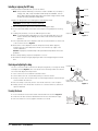
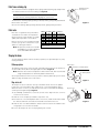
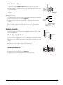
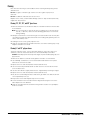
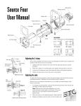
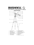
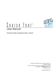
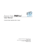
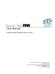
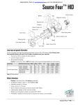
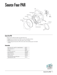
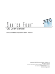
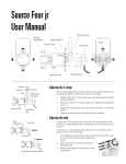
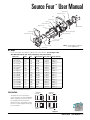
Source Four User Manual
ª
Lamp housing
Reflector housing
Yoke
Retainer bolt
Shutters
Pattern holder slot
Drop-in iris slot
Insulated handle
Yoke locking knob
Color frame
Barrel rotation knob
Color frame holder
Barrel
Beam focus knob
Lens tube
Note: Safety cable is included
for cUL applications.
Retaining clip
HPL lamps
Do not use lamps other than the HPL in Source Four fixtures. Use of lamps other
than HPL will void UL/cUL safety compliance and your warranty.
Lamp code
HPL 750/115
HPL 575/115
HPL 575/115X
HPL 575/120
HPL 375/115
HPL 375/115X
HPL 550/77*
HPL 550/77X*
HPL 750/220
HPL 750/230
HPL 750/240
HPL 575/230
HPL 575/240
HPL 575/230X
HPL 575/240X
HPL 375/230X
HPL 375/240X
Watts
750
575
575
575
375
375
550
550
750
750
750
575
575
575
575
375
375
Volts
115
115
115
120
115
115
77
77
220
230
240
230
240
230
240
230
240
Initial Lumens Color temp. Average rated life
21,900
3,250º K
300 hour
16,520
3,250º K
300 hour
12,360
3,050º K
2,000 hour
16,460
3,250º K
300 hour
10,540
3,200º K
300 hour
8,068
3.000º K
1000 hour
16,170
3,250º K
300 hour
12,160
3.050º K
2,000 hour
19,400
3,200º K
300 hour
19,400
3,200º K
300 hour
19,400
3,200º K
300 hour
14,900
3,200º K
400 hour
14,900
3,200º K
400 hour
11,780
3,050º K
1500 hour
11,780
3,050º K
1500 hour
7,800
3,050º K
1000 hour
7,800
3,050º K
1000 hour
Table 1: HPL lamp reference
*To be used with ETC Dimmer Doubler™
Lens locations
19° (6x16)
Red dot
26° (6x12)
Black dot
36° (6x9)
Dotless
50° (4.5x6)
Yellow dot
The different lenses used in the
Source Four are not interchangeable.
When installing a new lens, refer to
the illustration below for proper
placement. Also, remember to have
the lens’ color designator dot facing
the color frame.
Figure 1
Source Four User Manual • 1
Installing or replacing the HPL lamp
HPL Lamp
A lamp must be installed before you use the fixture.
Note: Verify that the HPL lamp you intend to install is suitable for your facility's
voltage; 115-, 120-, 230-, and 240-volt HPL lamps are available. See the
above table. Operating HPL lamps above their rated voltage reduces lamp
life and can cause premature lamp failure.
Lamp base
Replace the lamp if it becomes damaged or thermally deformed.
WARNING! Let the lamp cool before replacing.
Lamp
retention
brackets
Lamp
retaining clip
1. Disconnect power to the Source Four before installing the lamp.
2. Loosen the knurled bolt on the back of the lamp housing and pull the housing
out.
3. Holding it by the base, remove the HPL lamp from its box.
Knurled bolt
Lamp housing
Note: To avoid premature lamp failure, do not touch the lamp glass. If you do,
clean it carefully with rubbing alcohol and a clean lint-free cloth before
operation.
Figure 2
4. Line up the flat sides of the lamp base with the retention brackets on either side
of the socket as show in Figure 2.
5. Push down on the lamp base until the lamp seats firmly. (When properly
installed, the top of the lamp's base will be even with the top edges of the
retention brackets).
Caution! Improperly installed lamps cause premature lamp failure and socket
problems.
6. Press lamp retaining clip across lamp base to secure.
7. Reinstall the lamp housing by aligning the bolt hole and tightening the knurled
bolt.
Centering and adjusting the lamp
The two concentric knobs located on the lamp housing allow you to align the lamp
and adjust its field (Figure 3). The outer knob centers the lamp within the reflector.
The inner knob adjusts the lamp's field.
Rear lamp housing
1. Turn on the Source Four and aim it at a flat surface.
2. Unlock and loosen the outer knob by turning it counterclockwise.
3. Gently move the outer knob from side to side and up and down until the lamp is
centered within the reflector.
4. Once the lamp is centered, turn the outer knob clockwise to lock it in place.
Center within the
Adjust peak or flat field
reflector (outer knob) (inner knob)
Figure 3
5. Finally, turn the inner knob either clockwise or counterclockwise to achieve an
optimum flat field.
Focusing the beam
1. Loosen the beam focus knob located under the barrel as shown in Figure 4.
2. Slide the lens tube forward or backward to achieve the desired beam edge.
3. Once the fixture is focused, tighten the beam focus knob.
Beam focus knob
2 • Source Four User Manual
Figure 4
Color frame retaining clip
Retaining clip in the
locked position
The color frame holder is equipped with a spring-loaded retaining clip that prevents
color frames and accessories from falling out (Figure 5).
WARNING! Make sure all color frame accessories are locked in
position with the retaining clip before hanging the Source Four.
1. Release the retaining clip by pushing it sideways while gently pulling backwards.
Figure 5
2. Insert the color frame.
3. Lock the retaining clip by pushing sideways while gently pushing forward.
Color notes
ETC does not guarantee the performance
of saturated colors with low temperature
ranges. For best results, always use a high
quality and temperature color medium.
ETC's Source Four color extender may help
increase your gel life. Contact ETC or your
dealer for ordering information.
Note: An optional conical color extender
is available for use with saturated
colors and 750W HPL lamps.
Fixture Soft Focus Sharp Soft Focus
Version Tube Back Focus Tube Forward
5º
✔
✔
✔
10º
✔
✔
✔
19º
✘
✔
✔
26º
✘
✔
✔
36º
✔
✔
✘
50º
✘
✔
✔
✔=Better gel life
✘=Worse gel life
Shaping the beam
You may shape the beam with the shutters, a pattern, an optional drop-in iris, or by
rotating the barrel.
Pattern projection
Pattern holders
A-size holds 3” diameter patterns
The pattern holder slot is on the top side of the barrel and in front of the shutters. It
accommodates A-size, B-size and glass pattern holders (Figure 6).
Note: Because the Source Four aperture is three inches wide, ETC recommends
using A-size patterns for maximum pattern effectiveness.
Use an optional donut in the accessory holder to enhance pattern projection. Donut
diameter range should be 2.5 to 2.75 inches.
B-size holds 2.75” and
2.5” diameter patterns
3.12" dia.
3.70"
3.70"
Drop-in iris slot
The drop-in iris slot is located on the top of the barrel and in front of the pattern
holder slot. It accommodates either a drop-in iris or a motorized pattern device.
When the slot is not in use, a small sheet metal cover secured with two Phillips
screws prevents light leakage (Figure 7).
2.75" dia.
Figure 6
Drop-in iris slot
Iris
1. Use a Phillips screwdriver to loosen the screws on the drop-in iris slot cover. Do
not remove the screws.
2. Slide the cover completely forward to expose the slot.
3. Insert the iris or motorized pattern device. For an iris, install the flat side toward
the shutters and make sure that the iris handle extends from the slot.
Figure 7
4. Slide the slot cover back toward the shutters until it meets the iris handle. Leave
enough space to move the iris handle.
5. Secure the drop-in iris slot cover by tightening the screws.
Source Four User Manual • 3
Rotating the barrel assembly
1. Loosen the barrel rotation knob directly behind the shutters on the underside of
the reflector housing (Figure 8). Do not remove the barrel rotation knob.
2. Rotate the barrel to the desired position (up to 25° in either direction from the
centered position).
3. Once the barrel is positioned, tighten the barrel's rotation knob to lock it into
position.
Barrel rotation knob
Adjusting the C-clamp
The C-clamp attaches the fixture to the mounting pipe and allows you to adjust the
position of the fixture once it is mounted (Figure 9).
1. Tightly fasten the C-clamp to the yoke with the provided yoke bolt and lock
washer.
Figure 8
ET C
C-clamp
Pan screw
Pipe bolt
Yoke bolt and
lock washer
Yoke
2. Place the C-clamp on mounting pipe, then tighten the pipe bolt to secure it.
3. Loosen the C-clamp pan screw and rotate the yoke to the desired position.
Figure 9
4. Tighten the pan screw to lock the fixture into position.
Adjusting the yoke position
The Source Four provides multi-positioning capabilities within its yoke for overall
fixture height and angle.
High position
Low position
Setting the fixture height within the yoke
The Source Four has a two-position yoke for modifying the overall height in which
the fixture is mounted (Figure 10). To change the height position, do the following:
1. Remove the yoke locking knobs, washers, and hex bolts from either side of the
fixture.
Figure 10
2. Raise or lower the fixture to the desired position within the yoke.
3. Replace the yoke’s hex bolts, washers, and locking knobs.
4. Tighten the yoke knobs to secure the fixture in position.
Setting the angle within the yoke
1. Loosen the yoke locking knobs. (Do not remove them.)
2. Tilt the fixture to the desired position (Figure 11).
3. Tighten the yoke locking knobs to secure the fixture in position.
Yoke locking knob
Figure 11
4 • Source Four User Manual
Cleaning
ETC offers the following recommendations when cleaning and inspecting lenses
and reflectors:
Do not use glass or window type cleaners on lenses (glass or polymer) or
reflectors.
Do not use abrasive materials such as steel wool.
Replace lenses if they contain visible damage (cracks or deep scratches) that may
impair their effectiveness.
Cleaning 19°, 26°, 36°, and 50° glass lenses
1. Remove the beam focus knob at the bottom of the barrel. Remove the lens tube
from the barrel.
Note: It is not necessary to remove the lens for cleaning. If you do remove the
19°, 26°, or 50° lens, make sure the identifying paint dot is not removed
during cleaning.
2. Dampen a clean lint-free cloth with vinegar or household ammonia. You may also
use water, but it will leave spots that can be removed by gently polishing the lens
with a clean and dry cloth.
3. Starting from the center, gently wipe the lens.
4. Slide the lens tube back into the barrel with the color frame retaining clip on top.
Replace the beam focus knob.
Cleaning 5° and 10° polymer lenses
To quickly clean the lenses, remove dust with a blast of oil-free air. If this is not
sufficient, follow the instructions below. You will need a Phillips screwdriver.
Caution! Handle polymer lenses by their edges only. Never rub anything dry on a
polymer lens.
1. Remove the beam focus knob. Gently pull the lens tube out of the barrel.
2. Use a Phillips screwdriver to remove the brackets that hold the lens in place.
Remove the lens from the tube.
3. Dip the lens in a clean alcohol/water mixture (10% alcohol).
4. Use a moistened nylon bristle brush to wash the lens' smooth side in a linear
(non-circular) motion.
5. Use the same brush to lightly wash the lens' ridged side by following its ridges.
6. Dip the lens in a clean alcohol/water mixture (10% alcohol).
7. Dry the smooth and ridged surfaces with an air gun. Make sure that the air flow
moves liquid away from you.
8. Inspect the lens for dirt. Repeat steps 3-7 if necessary.
9. Set the lens back in the lens tube with the ridged side facing the front of the
tube. Replace the lens brackets.
10.Slide the lens tube back into the barrel with gel frame retainer on top. Replace
beam focus knob.
Source Four User Manual • 5
Cleaning the reflector
WARNING! Unplug the fixture before attempting to clean the reflector.
To quickly clean the reflector, remove the lens tube and clean the dust from the
reflector with a blast of oil-free air. You may also wipe the reflector with a clean lintfree cloth. If either method is not sufficient, follow the instructions below. You will
need a Phillips screwdriver to complete this procedure.
1. Remove the barrel rotation knob located at the bottom of the barrel. Use a
Phillips screwdriver to remove the retainer bolt located on top of the reflector
housing.
2. Rotate the barrel 45° in either direction. Carefully remove the barrel from the
reflector housing.
3. Dampen a clean lint-free cloth with alcohol or distilled water. (Alcohol is
recommended.)
4. Gently wipe the reflector.
5. Insert the barrel into the reflector housing with the iris/pattern slot on top. (Line
up the triangles on both parts.)
6. While pressing in gently, rotate the barrel 45° clockwise until it sets into position.
Then, rotate the barrel counterclockwise 45°. The barrel should be firmly
attached and the triangles should line up again.
7. Replace the barrel rotation knob and tighten the retainer bolt.
6 • Source Four User Manual
Source Four User Manual • 7
Electronic Theatre Controls
North America 3030 Laura Lane • Middleton, Wisconsin 53562 • USA • Tel: (+1) 608 831 4116 • Fax: (+1) 608 836 1736
Europe 5 Victoria Industrial Estate • Victoria Road • London W3 6UU • Tel: (+44) 181 896 1000 • Fax: (+44) 181 896 2000
Asia Room 605-606 • Tower III • Enterprise Square • 9 Sheung Yuet Road • Kowloon Bay • Hong Kong • Tel: (+852) 2799 1220 • Fax: (+852) 2799 9325
World Wide Web: http://www.etcconnect.com • Email: [email protected]
Specifications subject to change. Source Four is protected by US patent numbers 5,345,371, 5,446,637, 5,268,613 and 5,544,029;
Japanese Patent 2,501,772. US and International Patents Pending. 7060M1001.
Copyright 1999; Revised 12/99.