1
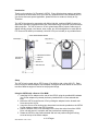
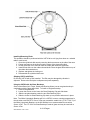
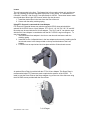
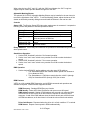
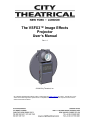
The VSFX3™ Image Effects
Projector
User’s Manual
Rev 1.6
© 2009 City Theatrical, Inc.
City Theatrical developed the VSFX3 system in partnership with White Light Ltd. of London. The VSFX3 is a new
version of the White Light VSFX System and it is compatible with the accessories for all previous versions of the
VSFX and the Patt 252 effects.
Contents
Safety Notices ....................................................................................................................... 2
Compliance Certifications.................................................................................................... 3
Introduction ........................................................................................................................... 4
Setup ...................................................................................................................................... 4
Using the VSFX3 with a Source 4 Par MCM ....................................................................... 4
S 4 Lamps .............................................................................................................................. 5
Mounting on a Juliat 325 LFX .............................................................................................. 5
Using the VSFX3 with Other Lighting Fixtures .................................................................. 5
Mains Connection ................................................................................................................. 5
Installing/Removing Disks ................................................................................................... 6
Shipping VSFX3 with Disks ................................................................................................. 6
Using the VSFX3 with Art Glass Breakups......................................................................... 6
Lenses.................................................................................................................................... 7
Using ETC Source 4 Lenses and the Lens Adapter .......................................................... 7
Adjustable Masking Shutter................................................................................................. 8
Controls ................................................................................................................................. 8
Stand Alone Operation ......................................................................................................... 8
DMX Operation ...................................................................................................................... 8
RDM Features........................................................................................................................ 8
VSFX3 never stops ............................................................................................................... 9
Warranty ................................................................................................................................ 9
Safety Notices
Please read this entire manual before using your new equipment. Please keep the manual
in a safe place so you can refer to it in the future as required.
The CTI VSFX3 is intended for use only by qualified professionals. Connection, installation
and hanging of this equipment must be performed in accordance with all pertinent local,
regional and national safety codes and regulations.
The CTI VSFX3 is intended for indoor use only unless specified for outdoor use.
Keep the equipment dry. Do not operate the equipment if it gets wet.
Do not operate in excessive heat/direct sunlight.
Be sure installation provides adequate ventilation. Some system components can produce
significant heat and must be properly installed to allow proper cooling and assure user
safety. All sides of the equipment must be clear of obstruction and allow free airflow.
There are no user-serviceable parts inside. Refer to qualified service personnel.
The socket/outlet serving this unit must be installed near the equipment and be easily
accessible.
2 of 10 Pages
5400 Manual R1.6.doc 3/4/10
Compliance Certifications
The VSFX3 is CE certified
Standards Applied:
BS EN 60950-1:2002 incorporating Corrigendum No. 1 and Amendment No. 1
EN 55203-1: 1996
EN 55203-2: 1996
The VSFX3 is ETL Listed
The VSFX3 Conforms to UL STD 508A and is Certified to CAN/CSA STD C22.2
NO. 14-95
3 of 10 Pages
5400 Manual R1.6.doc 3/4/10
Introduction
Thank you for selecting City Theatrical’s VSFX3. Every effort has been made to anticipate
your questions in this manual, but if you have any questions that are not answered here, or
you want to discuss a special application, please feel free to contact us directly at City
Theatrical.
The VSFX3, developed in cooperation with White Light Ltd, combines DMX512 control (or
stand alone operation) with advanced motor control technology to provide quiet and smooth
effect projection. The VSFX3 uses an 18” dia. glass image disk to project a wide range of
effects including clouds, rain, flames, snow, water, etc. and is designed to be used with the
ETC Source4 Par MCM (not included), Juliat 325 LFX (not included) or any suitable fixture.
Setup
The VSFX3 can be used with an ETC Source 4 Par MCM or with a Juliat 325 LFX. Each
fixture requires a different adapter. Each adapter is designed to allow rotation of the VSFX3
to achieve different angles of motion for the projected image.
Using the VSFX3 with a Source 4 Par MCM
1. Install the S4 Par adapter on the rear of the VSFX3 using the provided M5 hardware
(the S4 Par adapter may already be factory installed if the unit was ordered that
way).
2. Mount the VSFX3 to the Source 4 Par by sliding the adapter into the forward color
frame slot on the S4 Par.
3. Lower the Source 4 Par locking color frame latch into the slot provided on the VSFX3
S4 Par adapter to secure the VSFX3 in place.
4. Slide the desired VSFX Lens Assembly into the Lens slot at the front of the VSFX3
Drive unit and secure it in position with the provided lens retaining spring.
5. Rotate the VSFX3 to the position desired and lock into position using the locking
screw at the top of the fixture adapter.
4 of 10 Pages
5400 Manual R1.6.doc 3/4/10
6. Connect the safety cable to the safety cable clip at the front of the VSFX3 and secure
it to a suitable point.
S 4 Lamps
When using the VSFX3 with a Source 4 Par MCM, the fixture can be provided with either a
375W or 575W lamp.
Mounting on a Juliat 325 LFX
7. Install the Juliat 325 LFX adapter on the rear of the VSFX3 using the provide M5
hardware (the Juliat 325 LFX adapter may already be factory installed if the unit was
ordered that way).
8. Mount the VSFX3 to the Juliat 325 LFX by sliding the adapter into the forward color
frame slot on the Juliat 325 LFX.
9. Slide the desired VSFX Lens Assembly into the Lens slot at the front of the VSFX3
Drive unit and secure it in position with the provided lens retaining spring.
10. Rotate the VSFX3 to the position desired and lock into position using the locking
screw at the top of the fixture adapter.
11. Connect the safety cable to the safety cable clip at the front of the VSFX3 and secure
it to a suitable point.
Using the VSFX3 with Other Lighting Fixtures
The VSFX3 may be used with a lighting fixture other than the Source 4 Par MCM (575W
max) or the Juliat 325 LFX, providing the disk or breakup temperature does not exceed
190ºF/87.7ºC. Extended disk operating temperatures above 190ºF/87.7ºC may reduce disk
life. In addition, the maximum allowable operating temperature of the electronics
compartment is 104ºF/40ºC. In any case, the unit should not be used in any application that
would result in an unsafe condition.
Mains Connection
The VSFX3 contains a universal power supply and so will operate with 100-240VAC
50/60Hz mains voltage, and is fitted with an IEC C-14 mains inlet for power cable
connection.
Units sold in the EU are provided with IEC C-13 to bare end power cables in standard EU
color code (Brown = Hot, Blue = Neutral, Yellow/Green = Earth). Follow the color code
when installing the desired connector for the locality where the VSFX3 is to be used.
Units sold in North America are provided With IEC C-13 to NEMA 5-15P (“Edison”) power
cables.
Never power the VSFX3 from a dimmer. Failure to ensure this may result in damage to the
power supply, motor and/or control electronics which will not be covered under warranty
The VSFX3 must always be running when the fixture is turned on. Failure to ensure this
may result in damage to the disk which will not be covered under warranty.
5 of 10 Pages
5400 Manual R1.6.doc 3/4/10
Installing/Removing Disks
This operation should be performed with the VSFX3 drive unit lying face down on a suitable
table or work bench.
1. Open the cylindrical disk case by removing the three screws on the side of the case.
2. Loosen and remove the locking nut at the center of the glass effect disk.
3. Lift the glass disk out to remove. Note the rubber disk under the glass disk.
4. Install a new disk over the rubber-sleeved shaft. Place the glass effect disk on top of
the rubber disk noted above.
5. Replace and tighten the locking nut.
6. Reassemble the cylindrical disk case.
Shipping VSFX3 with Disks
Do not ship VSFX3 with a Disk installed. The Disk may be damaged by vibration in
shipment. Remove the Disk prior to shipment and pack separately.
Using the VSFX3 with Art Glass Breakups
Some of the effects (incl. Flame, Smoke and Running Water) use an art glass breakup in
combination with the glass effect disk. To install an art glass breakup:
1. Remove the glass disk
2. Loosen the screws on the Lower Art Glass Retaining Clip and slide down.
3. Slide the art glass breakup under the two Side Retaining Clips.
4. Slide the Lower Art Glass Retaining Clip back up into position and secure in place.
Note: The White Light plastic Breakup will fit in a VSFX3, however running temperatures in
the unit when used with ETC Source 4 Par may exceed the usable limit (~170º F/76.6º C) of
the White Light plastic Breakup, so the WL Breakup is not recommended for use with a
Source 4 Par. The CTI 5421 Art Glass Breakup is made of glass and may be used with a
Source 4 Par.
6 of 10 Pages
5400 Manual R1.6.doc 3/4/10
Lenses
The unit has two slots in the front. The forward slot is for mounting a lens unit, and the rear
slot is for installing the optional adjustable light mask or color frame. CTI manufactures a
6.5cm/90º, 10cm/50 º and 15cm/30 º lens specifically for VSFX3. These three lenses match
the original three White Light VSFX lenses, which may also be used.
1. Install the desired lens in the lens slot at the front of the unit.
2. Secure with the safety retaining spring.
Using ETC Source 4 Lenses and the Lens Adapter
ETC Source 4 Ellipsoidal lenses may also be used with VSFX3 when paired with the
optional 5416 VSFX3 Source 4 Lens Adapter. ETC S4 14º, 19º, 26º, 36º, 50º, 70º and 90º
lens tubes can be used with the 5416 Lens adapter. The S4 5° and 10° can also be used
with the 5416 Lens Adapter in combination with the 5417 VSFX3 Long Lens Support. To
use a lens adapter:
1. insert the desired lens adapter in the front or rear lens slot and secure with the
retaining spring
2. Install the Source 4 ellipsoidal lens in the lens adapter and secure by installing the S4
lens thumb screws in the slots provided on the top and the bottom of the Lens
Adapter.
3. Focus the lens as required and lock into place with the S4 lens thumb screws
An optional Donut Plate is provided with the CTI 5416 Lens Adapter This Donut Plate is
recommended when ETC lenses are used to optimize the aperture of the VSFX3. To
install, mount the Donut Plate on the fixture adapter ring on the rear of the disk case using
the 4 M3 PHP screws provided with the Donut Plate.
7 of 10 Pages
5400 Manual R1.6.doc 3/4/10
When using the long S4 5° and 10° c with the 5422 Lens Adapter, the 5417 Long lens
support may be used to provide additional support for the lens.
Adjustable Masking Shutter
The optional 5413 VSFX3 Adjustable Masking Shutter may be installed in the rear lens slot
to mask the light beam of the VSFX3. To use the Masking Shutter, adjust the leaves of the
shutter as desired by manually sliding them and install the Shutter in the rear lens slot.
Controls
Status LED: The Bi-color Status LED lights when mains power is connected. It outputs the
following colors and patterns to indicate operational status:
Blinking Red:
Blinking Green:
Blinking Amber:
Rapidly flashing
Red:
Address 600-799:
Address 800-999:
No DMX present
DMX present
DMX received but address is out of range
Noise and errors on DMX line
Blinking Green at a rate which varies with motor
speed
Slow flash Amber
Rotary Switches: Three rotary BCD switches are provided for DMX addressing and Standalone speed control.
Stand Alone Operation
1. Set the BCD “Hundreds” switch to 6 for forward operation.
2. Set the “tens” and “ones” switch to any number from 0-99 to select the desired
speed.
3. Set the BCD “Hundreds” switch to 7 for reverse operation.
4. Set the “tens” and “ones” switch to any number from 0-99 to select the desired
speed.
DMX Operation
1. Set the desired DMX512 starting address using the rotary BCD switches.
i. The Start address DMX slot controls rotation speed from slowest at
0% to fastest at 100%.
ii. The Start address +1 DMX slot controls direction, with 0% (through
49%) for forward and 50% (through 100%) for reverse.
RDM Features
VSFX3 is a fully enabled RDM Responder, and all RDM commands and operations are
available at anytime. RDM functions supported include:
RDM Discovery: Standard RDM Discovery function
RDM Identify: Status LED blinks Red/Green and motor runs at full speed
DMX Address control: Setting of DMX address will succeed only when the DMX
thumb wheels are set to 000. At all other times the request will receive a NACK
response. A read of the DMX address when the thumb wheels are at 000 will read
the RDM set address, at all other times it will read the value of the thumb wheels.
Driver fault Sensor: Reports whether the driver is in a fault condition. I.E. overload.
RPM Sensor: Reports current speed in RPM mathematically.
8 of 10 Pages
5400 Manual R1.6.doc 3/4/10
Select Preset Operation: You can initiate the built in speed settings by using RDM
presets. The preset number is the same as the corresponding thumb wheel value.
For example to use RDM to call up thumb wheel setting 750 (50% reverse direction),
issue a set preset 750 to the device. BCD preset settings are ignored.
Supported RDM parameters:
DISC_UNIQUE_BRANCH
DISC_MUTE
DISC_UN_MUTE
SUPPORTED_PARAMETERS
PARAMETER_DESCRIPTION
DEVICE_INFO
PRODUCT_DETAIL_ID_LIST
DEVICE_MODEL_DESCRIPTION
MANUFACTURER_LABEL
DEVICE_LABEL
FACTORY_DEFAULTS
SOFTWARE_VERSION_LABEL
DMX_START_ADDRESS
SENSOR_DEFINITION
SENSOR_VALUE
IDENTIFY_DEVICE
VSFX3 never stops
In order to protect the glass disks from burning or other heat damage, the VSFX3 moves in
every speed setting. When no DMX signal is present or if switches are set to 800-999, the
unit defaults to half full speed.
Warranty
City Theatrical, Inc. warrants to the original purchaser that the custom equipment offered will
be free from defects in workmanship and material for a period of one year from date of
purchase. During the warranty period, units will be repaired or replaced at the option of City
Theatrical Inc.
The warranty does not extend to any parts of the unit that have been subjected to misuse or
accident. Neither does the warranty cover any machine that has been modified or repaired at
other than an authorized repair station.
The warranty will not apply if procedures described in the Operations Manual are not
followed.
This warranty does not include shipping to or from City Theatrical, Inc.
Unless otherwise stipulated by state law, all warranties, expressed or implied, are limited to
the period of this warranty.
Customers requiring repair of their equipment should obtain an RGA# from City Theatrical.
Equipment should be suitably packaged, including a note with the owner's name and
address and a description of the reason for return. Ship package prepaid and insured. City
Theatrical cannot be responsible for loss or damage in shipment.
9 of 10 Pages
5400 Manual R1.6.doc 3/4/10
UNLESS EXCLUSIONS ARE SPECIFICALLY FORBIDDEN BY STATE LAW, CITY
THEATRICAL SHALL NOT BE LIABLE FOR INCIDENTAL OR CONSEQUENTIAL
DAMAGES ARISING FROM THE USE OR FAILURE OF THIS PRODUCT, INCLUDING
INJURY TO PERSONS OR PROPERTY.
10 of 10 Pages
5400 Manual R1.6.doc 3/4/10