1
Final draft ETSI
EN 303 098-1 V1.2.1 (2014-06)
EUROPEAN STANDARD
Electromagnetic compatibility and
Radio spectrum Matters (ERM);
Maritime low power personal locating devices employing AIS;
Part 1: Technical characteristics and methods of measurement
2
Final draft ETSI EN 303 098-1 V1.2.1 (2014-06)
Reference
DEN/ERM-TG26-100-1
Keywords
maritime, radio, SAR, testing
ETSI
650 Route des Lucioles
F-06921 Sophia Antipolis Cedex - FRANCE
Tel.: +33 4 92 94 42 00 Fax: +33 4 93 65 47 16
Siret N° 348 623 562 00017 - NAF 742 C
Association à but non lucratif enregistrée à la
Sous-Préfecture de Grasse (06) N° 7803/88
Important notice
The present document can be downloaded from:
http://www.etsi.org
The present document may be made available in electronic versions and/or in print. The content of any electronic and/or
print versions of the present document shall not be modified without the prior written authorization of ETSI. In case of any
existing or perceived difference in contents between such versions and/or in print, the only prevailing document is the
print of the Portable Document Format (PDF) version kept on a specific network drive within ETSI Secretariat.
Users of the present document should be aware that the document may be subject to revision or change of status.
Information on the current status of this and other ETSI documents is available at
http://portal.etsi.org/tb/status/status.asp
If you find errors in the present document, please send your comment to one of the following services:
http://portal.etsi.org/chaircor/ETSI_support.asp
Copyright Notification
No part may be reproduced or utilized in any form or by any means, electronic or mechanical, including photocopying
and microfilm except as authorized by written permission of ETSI.
The content of the PDF version shall not be modified without the written authorization of ETSI.
The copyright and the foregoing restriction extend to reproduction in all media.
© European Telecommunications Standards Institute 2014.
All rights reserved.
TM
TM
TM
DECT , PLUGTESTS , UMTS and the ETSI logo are Trade Marks of ETSI registered for the benefit of its Members.
TM
3GPP and LTE™ are Trade Marks of ETSI registered for the benefit of its Members and
of the 3GPP Organizational Partners.
GSM® and the GSM logo are Trade Marks registered and owned by the GSM Association.
ETSI
3
Final draft ETSI EN 303 098-1 V1.2.1 (2014-06)
Contents
Intellectual Property Rights ................................................................................................................................7
Foreword.............................................................................................................................................................7
Modal verbs terminology....................................................................................................................................7
1
Scope ........................................................................................................................................................8
2
References ................................................................................................................................................8
2.1
2.2
3
3.1
3.2
3.3
4
4.1
4.1.1
4.2
4.3
4.4
4.5
4.5.1
4.6
4.7
4.7.1
4.7.2
4.7.3
5
5.1
5.2
5.2.1
5.2.1.1
5.2.1.2
5.2.2
5.2.2.1
5.2.2.2
5.2.3
5.2.3.1
5.2.3.2
5.2.4
5.2.5
5.2.6
5.2.6.1
5.2.6.2
6
6.1
6.2
6.3
6.4
6.5
6.5.1
6.5.2
6.5.3
6.5.4
6.6
Normative references ......................................................................................................................................... 8
Informative references ........................................................................................................................................ 9
Definitions, symbols and abbreviations ...................................................................................................9
Definitions .......................................................................................................................................................... 9
Symbols .............................................................................................................................................................. 9
Abbreviations ..................................................................................................................................................... 9
General requirements .............................................................................................................................10
Construction ..................................................................................................................................................... 10
Categories of equipment ............................................................................................................................. 11
Controls ............................................................................................................................................................ 11
Indicators .......................................................................................................................................................... 11
Identifier (user ID)............................................................................................................................................ 11
Labelling........................................................................................................................................................... 12
Labelling Requirements .............................................................................................................................. 12
Instructions ....................................................................................................................................................... 12
Power source .................................................................................................................................................... 12
Battery requirements ................................................................................................................................... 12
Battery capacity .......................................................................................................................................... 13
Safety precautions ....................................................................................................................................... 13
Technical requirements ..........................................................................................................................13
General ............................................................................................................................................................. 13
AIS transmission characteristics....................................................................................................................... 13
AIS messages .............................................................................................................................................. 13
Active mode .......................................................................................................................................... 14
Test mode .............................................................................................................................................. 14
Synchronization .......................................................................................................................................... 14
Active mode .......................................................................................................................................... 14
Test mode .............................................................................................................................................. 14
GNSS position source ................................................................................................................................. 14
UTC....................................................................................................................................................... 15
UTC parameters storage ........................................................................................................................ 15
Required settings ........................................................................................................................................ 15
Minimum transmitter performance characteristics ..................................................................................... 16
VHF Data Link (VDL) Access ................................................................................................................... 16
Active mode .......................................................................................................................................... 16
Test mode .............................................................................................................................................. 17
General conditions of measurement .......................................................................................................17
Conformity testing............................................................................................................................................ 17
Test Frequencies ............................................................................................................................................... 17
Identifier (user ID)............................................................................................................................................ 17
Artificial Antenna ............................................................................................................................................. 17
Test signals ....................................................................................................................................................... 18
Standard test signal number 1 ..................................................................................................................... 18
Standard test signal number 2 ..................................................................................................................... 18
Standard test signal number 3 ..................................................................................................................... 18
Reference timing signal .............................................................................................................................. 18
Measurement uncertainty and interpretation of the measured results .............................................................. 18
ETSI
4
6.6.1
6.6.2
6.7
6.7.1
6.7.2
6.8
6.8.1
6.8.2
6.9
6.9.1
6.9.1.1
6.9.2
6.9.2.1
6.9.2.2
7
7.1
7.2
7.3
7.4
7.4.1
7.4.2
7.4.3
7.4.4
7.5
7.5.1
7.5.2
7.5.2.1
7.5.2.2
7.5.3
7.5.3.1
7.5.3.2
7.5.4
7.5.4.1
7.5.4.2
7.5.5
7.5.5.1
7.5.5.2
7.6
7.6.1
7.6.2
7.6.3
7.7
7.7.1
7.7.2
7.7.3
7.8
7.8.1
7.8.2
7.8.3
7.9
7.9.1
7.9.2
7.9.3
7.10
7.10.1
7.10.2
7.10.3
7.11
7.11.1
7.11.2
7.11.3
Final draft ETSI EN 303 098-1 V1.2.1 (2014-06)
Measurement uncertainty ............................................................................................................................ 18
Interpretation of the measurement results ................................................................................................... 19
Test conditions power sources and ambient temperatures................................................................................ 19
Normal and extreme test conditions............................................................................................................ 19
Test power source ....................................................................................................................................... 19
Normal test conditions...................................................................................................................................... 19
Normal temperature and humidity .............................................................................................................. 19
Normal test voltage ..................................................................................................................................... 19
Extreme test conditions .................................................................................................................................... 19
Extreme temperatures ................................................................................................................................. 19
Procedure for tests at extreme temperatures .......................................................................................... 20
Extreme test voltages .................................................................................................................................. 20
Upper extreme test voltage .................................................................................................................... 20
Lower extreme test voltage ................................................................................................................... 20
Environmental tests ................................................................................................................................20
Introduction ...................................................................................................................................................... 20
Procedure.......................................................................................................................................................... 20
Performance check ........................................................................................................................................... 20
Drop test ........................................................................................................................................................... 20
Definition .................................................................................................................................................... 20
Test conditions ............................................................................................................................................ 21
Method of measurement ............................................................................................................................. 21
Requirements .............................................................................................................................................. 21
Temperature tests ............................................................................................................................................. 21
Definition .................................................................................................................................................... 21
Dry heat test ................................................................................................................................................ 21
Method of measurement ........................................................................................................................ 21
Requirements ........................................................................................................................................ 22
Damp heat test ............................................................................................................................................ 22
Method of measurement ........................................................................................................................ 22
Requirements ........................................................................................................................................ 22
Low temperature test .................................................................................................................................. 22
Method of measurement ........................................................................................................................ 22
Requirements ........................................................................................................................................ 22
Low temperature battery endurance test ..................................................................................................... 23
Method of measurement ........................................................................................................................ 23
Requirements ........................................................................................................................................ 23
Vibration test .................................................................................................................................................... 23
Definition .................................................................................................................................................... 23
Method of measurement ............................................................................................................................. 23
Requirement ................................................................................................................................................ 24
Corrosion test ................................................................................................................................................... 24
Definition .................................................................................................................................................... 24
Method of measurement ............................................................................................................................. 24
Requirements .............................................................................................................................................. 24
Thermal shock test............................................................................................................................................ 25
Definition .................................................................................................................................................... 25
Method of measurement ............................................................................................................................. 25
Requirements .............................................................................................................................................. 25
Buoyancy test ................................................................................................................................................... 25
Definition .................................................................................................................................................... 25
Method of measurement ............................................................................................................................. 25
Requirements .............................................................................................................................................. 25
Compass safe distance test ............................................................................................................................... 26
Definition .................................................................................................................................................... 26
Method of measurement ............................................................................................................................. 26
Requirements .............................................................................................................................................. 26
Solar radiation test ............................................................................................................................................ 27
Definition .................................................................................................................................................... 27
Method of measurement ............................................................................................................................. 27
Requirements .............................................................................................................................................. 27
ETSI
5
7.12
7.12.1
7.12.2
7.12.3
7.13
7.13.1
7.13.2
7.13.3
8
8.1
8.1.1
8.1.2
8.1.3
8.2
8.2.1
8.2.2
8.2.3
8.3
8.3.1
8.3.2
8.3.3
8.4
8.4.1
8.4.2
8.4.3
8.5
8.5.1
8.5.2
8.5.3
8.6
8.6.1
8.6.2
8.6.3
8.7
8.7.1
8.7.2
8.7.3
8.8
8.8.1
8.8.2
8.8.3
9
9.1
9.1.1
9.1.2
9.1.3
9.1.4
9.1.5
9.1.6
9.1.7
9.1.8
9.2
9.2.1
9.2.2
9.3
9.3.1
9.3.2
Oil resistance test.............................................................................................................................................. 27
Definition .................................................................................................................................................... 27
Method of measurement ............................................................................................................................. 27
Requirements .............................................................................................................................................. 28
Protection of the transmitter ............................................................................................................................. 28
Definition .................................................................................................................................................... 28
Method of measurement ............................................................................................................................. 28
Requirement ................................................................................................................................................ 28
Tests on the AIS transmitter ...................................................................................................................28
Frequency error ................................................................................................................................................ 28
Definition .................................................................................................................................................... 28
Method of measurement ............................................................................................................................. 28
Limit ........................................................................................................................................................... 29
Conducted Power ............................................................................................................................................. 29
Definition .................................................................................................................................................... 29
Method of measurement under normal test conditions ............................................................................... 29
Limit ........................................................................................................................................................... 29
Maximum Effective Radiated Power (ERP)..................................................................................................... 29
Definition .................................................................................................................................................... 29
Method of measurement ............................................................................................................................. 29
Limits .......................................................................................................................................................... 30
Transmitter spectrum mask .............................................................................................................................. 30
Definition .................................................................................................................................................... 30
Method of measurement ............................................................................................................................. 30
Limit ........................................................................................................................................................... 31
Transmitter transient behaviour (output power) ............................................................................................... 31
Definition .................................................................................................................................................... 31
Method of measurement ............................................................................................................................. 32
Limit ........................................................................................................................................................... 33
Transmitter Transient Behaviour (frequency deviation) .................................................................................. 33
Definition .................................................................................................................................................... 33
Method of measurement ............................................................................................................................. 33
Limit ........................................................................................................................................................... 34
Synchronization accuracy................................................................................................................................. 34
Definition .................................................................................................................................................... 34
Method of measurement ............................................................................................................................. 34
Limit ........................................................................................................................................................... 35
Spurious emissions ........................................................................................................................................... 36
Definition .................................................................................................................................................... 36
Method of measurement ............................................................................................................................. 36
Limit ........................................................................................................................................................... 36
VDL Link layer tests ..............................................................................................................................36
Active mode tests ............................................................................................................................................. 36
Method of measurement ............................................................................................................................. 36
Initialization period - Required results........................................................................................................ 37
Message content of Message 1 - Required results ...................................................................................... 37
Message content of Message 14 - Required results .................................................................................... 37
Transmission schedule for Message 1 - Required results ........................................................................... 37
Communication state of Message 1 - Required results ............................................................................... 38
Transmission schedule of Message 14 - Required results........................................................................... 38
Transmission with lost GNSS - Required results ........................................................................................ 38
Test mode tests with GNSS data available ....................................................................................................... 39
Method of measurement ............................................................................................................................. 39
Required results .......................................................................................................................................... 39
Test mode tests without GNSS data available .................................................................................................. 39
Method of measurement ............................................................................................................................. 39
Required results .......................................................................................................................................... 39
Annex A (normative):
A.1
Final draft ETSI EN 303 098-1 V1.2.1 (2014-06)
Radiated measurements ................................................................................40
Test sites and general arrangements for measurements involving the use of radiated fields .................40
ETSI
6
A.1.1
A.1.2
A.1.3
A.1.4
A.1.5
A.1.6
A.2
A.2.1
A.2.2
A.2.3
A.2.4
A.2.5
A.2.6
A.3
A.3.1
A.3.2
A.4
A.4.1
A.4.2
Final draft ETSI EN 303 098-1 V1.2.1 (2014-06)
Anechoic chamber ............................................................................................................................................ 40
Anechoic chamber with a ground plane ........................................................................................................... 41
OATS ............................................................................................................................................................... 42
Test antenna...................................................................................................................................................... 43
Substitution antenna ......................................................................................................................................... 43
Measuring antenna ........................................................................................................................................... 44
Guidance on the use of radiation test sites .............................................................................................44
Verification of the test site ............................................................................................................................... 44
Preparation of the EUT..................................................................................................................................... 44
Power supplies to the EUT ............................................................................................................................... 44
Volume control setting for analogue speech tests ............................................................................................ 44
Range length ..................................................................................................................................................... 45
Site preparation ................................................................................................................................................ 45
Coupling of signals.................................................................................................................................46
General ............................................................................................................................................................. 46
Data signals ...................................................................................................................................................... 46
Standard position ....................................................................................................................................46
Artificial human support .................................................................................................................................. 46
Float-free support ............................................................................................................................................. 47
Annex B (normative):
Locating device message bursts ....................................................................48
B.1
Active mode ...........................................................................................................................................48
B.2
Test mode ...............................................................................................................................................49
B.3
Default message field values ..................................................................................................................50
Annex C (informative):
Bibliography ...................................................................................................51
History ..............................................................................................................................................................52
ETSI
7
Final draft ETSI EN 303 098-1 V1.2.1 (2014-06)
Intellectual Property Rights
IPRs essential or potentially essential to the present document may have been declared to ETSI. The information
pertaining to these essential IPRs, if any, is publicly available for ETSI members and non-members, and can be found
in ETSI SR 000 314: "Intellectual Property Rights (IPRs); Essential, or potentially Essential, IPRs notified to ETSI in
respect of ETSI standards", which is available from the ETSI Secretariat. Latest updates are available on the ETSI Web
server (http://ipr.etsi.org).
Pursuant to the ETSI IPR Policy, no investigation, including IPR searches, has been carried out by ETSI. No guarantee
can be given as to the existence of other IPRs not referenced in ETSI SR 000 314 (or the updates on the ETSI Web
server) which are, or may be, or may become, essential to the present document.
Foreword
This final draft European Standard (EN) has been produced by ETSI Technical Committee Electromagnetic
compatibility and Radio spectrum Matters (ERM), and is now submitted for the Vote phase of the ETSI standards EN
Approval Procedure.
The present document is part 1 of a multi-part deliverable covering the Electromagnetic compatibility and Radio
spectrum Matters (ERM); Maritime low power personal locating devices employing AIS, as identified below:
Part 1:
"Technical characteristics and methods of measurement";
Part 2:
"Harmonized EN covering the essential requirements of article 3.2 of the R&TTE Directive";
Proposed national transposition dates
Date of latest announcement of this EN (doa):
3 months after ETSI publication
Date of latest publication of new National Standard
or endorsement of this EN (dop/e):
6 months after doa
Date of withdrawal of any conflicting National Standard (dow):
18 months after doa
Modal verbs terminology
In the present document "shall", "shall not", "should", "should not", "may", "may not", "need", "need not", "will",
"will not", "can" and "cannot" are to be interpreted as described in clause 3.2 of the ETSI Drafting Rules (Verbal forms
for the expression of provisions).
"must" and "must not" are NOT allowed in ETSI deliverables except when used in direct citation.
ETSI
8
1
Final draft ETSI EN 303 098-1 V1.2.1 (2014-06)
Scope
The present document lays down the minimum requirements for low power maritime personal locating devices
employing AIS and an integrated GNSS receiver to provide the locating function. The present document incorporates
the relevant provisions of the International Telecommunication Union (ITU) radio regulations [i.3] included in
Recommendation ITU-R M.1371-5 [1].
For this application, both the radiated power and the length of time of operation are limited to enable the equipment to
be sufficiently small and light to be worn comfortably at all times and to limit the operating range to a local area.
2
References
References are either specific (identified by date of publication and/or edition number or version number) or
non-specific. For specific references, only the cited version applies. For non-specific references, the latest version of the
reference document (including any amendments) applies.
Referenced documents which are not found to be publicly available in the expected location might be found at
http://docbox.etsi.org/Reference.
NOTE:
2.1
While any hyperlinks included in this clause were valid at the time of publication, ETSI cannot guarantee
their long term validity.
Normative references
The following referenced documents are necessary for the application of the present document.
[1]
Recommendation ITU-R M.1371-5 (02/2014): "Technical characteristics for an automatic
identification system using time-division multiple access in the VHF maritime mobile band".
[2]
ETSI TR 100 028 (all parts) (V1.4.1): "Electromagnetic compatibility and Radio spectrum Matters
(ERM); Uncertainties in the measurement of mobile radio equipment characteristics".
[3]
ETSI TR 102 273-7 (2001): "Electromagnetic compatibility and Radio spectrum Matters (ERM);
Improvement on Radiated Methods of Measurement (using test site) and evaluation of the
corresponding measurement uncertainties; Part 7: Artificial human beings".
[4]
CENELEC EN 61108-1 (2003): "Maritime navigation and radiocommunication equipment and
systems - Global navigation satellite systems (GNSS) - Part 1: Global positioning system (GPS) Receiver equipment - Performance standards, methods of testing and required test results".
[5]
CENELEC EN 61108-2 (1998): "Maritime navigation and radiocommunication equipment and
systems - Global navigation satellite systems (GNSS) - Part 2: Global navigation satellite system
(GLONASS) - Receiver equipment - Performance standards, methods of testing and required test
results".
[6]
CENELEC EN 61108-3 (2010): "Maritime navigation and radiocommunication equipment and
systems - Global navigation satellite systems (GNSS) - Part 3: Galileo receiver equipment Performance requirements, methods of testing and required test results".
[7]
Recommendation ITU-T O.153 (10/1992): "Basic parameters for the measurement of error
performance at bit rates below the primary rate".
[8]
IMO ANNEX 11 - RESOLUTION MSC.149(77) - (adopted on 3 June 2003): "Adoption of the
revised performance standards for survival craft portable two-way VHF radiotelephone apparatus".
ETSI
9
2.2
Final draft ETSI EN 303 098-1 V1.2.1 (2014-06)
Informative references
The following referenced documents are not necessary for the application of the present document but they assist the
user with regard to a particular subject area.
[i.1]
ETSI TR 102 273 (Parts 2, 3 and 4) (V1.2.1): "Electromagnetic compatibility and Radio spectrum
Matters (ERM); Improvement on Radiated Methods of Measurement (using test site) and
evaluation of the corresponding measurement uncertainties".
[i.2]
ANSI C63.5-2006: "American National Standard for Calibration of Antennas Used for Radiated
Emission Measurements in Electro Magnetic Interference".
[i.3]
ITU-R Radio Regulations 2012.
3
Definitions, symbols and abbreviations
3.1
Definitions
For the purposes of the present document, the following terms and definitions apply:
active mode: activated mode, transmitting in an emergency situation
test mode: self testing mode, not involved in a genuine emergency
UTC lock: GNSS has precisely locked to UTC so that it can determine SOTDMA slot timing correctly.
UTC parameters: "Coordinated Universal Time (UTC) offset parameters" GNSS data that contains leap second offset
information
3.2
Symbols
For the purposes of the present document, the following symbols apply:
ε
σ
λ
cSt
dB
div
S
μT
3.3
permittivity
conductivity
wavelength
centi-Stokes
decibel
division
Siemens
microtesla
Abbreviations
For the purposes of the present document, the following abbreviations apply:
AIS
ASTM
CIRM
COG
CRC
CSP
CW
EIRP
ERP
EUT
GLONASS
GMSK
Automatic Identification System
American Society for Testing and Materials
Comité International Radio-Maritime
Course Over Ground
Cyclic Redundancy Check
Channel SPacing
Continuous Wave
Effective Isotropic Radiated Power
Effective Radiated Power
Equipment Under Test
GLObal NAvigation Satellite System (Russian system)
Gaussian Minimum Shift Keying
ETSI
10
GNSS
GPS
GTRF
IMO MSC
ISO
ITRF
ITU-R
ITU-T
MOB
NRZI
OATS
PPS
PZ-90
RAIM
RF
SOG
SOTDMA
TDMA
UTC
VDL
VHF
VSWR
WGS-84
Final draft ETSI EN 303 098-1 V1.2.1 (2014-06)
Global Navigation Satellite System
Global Positioning System
Galileo Terrestrial Reference Frame system
International Maritime Organization Maritime Safety Committee
International Organization for Standardization
International Terrestrial Reference Frame
International Telecommunication Union Radiocommunication sector
International Telecommunication Union Telecommunication sector
Man Over-Board
Non Return to Zero, Inverted
Open Area Test Site
Pulses Per Second
Parametry Zemli 1990
Receiver Autonomous Integrity Monitoring
Radio Frequency
Speed Over Ground
Self-Organized Time Division Multiple Access
Time Division Multiple Access
Coordinated Universal Time
VHF Data Link
Very High Frequency
Voltage Standing Wave Ratio
World Geodetic System 1984
4
General requirements
4.1
Construction
The manufacturer shall provide evidence that all requirements in clause 4 are fulfilled.
In all respects, the mechanical and electrical design and the construction and finish of the equipment shall conform with
good engineering practice.
The equipment shall be designed to minimize the risk of internal and external damage during use or stowage.
The exterior of the equipment shall have no sharp edges or projections that could easily damage inflatable rafts or injure
personnel.
The general construction and method of operation shall provide a high degree of proof against inadvertent operation due
to magnetic influences, handling, stowage and transit, whilst still providing a simple means of operation in an
emergency.
The equipment shall be portable, lightweight, compact and be designed as one integral unit. The locating device shall
derive its energy from a battery forming a part of the equipment and incorporate a permanently attached antenna which
may be either fixed length or extendible.
The locating device may be fitted with a test facility by which the functioning of the transmitter and battery can be
easily tested without the use of any external equipment.
The equipment shall be capable of being used by an unskilled person.
The locating device shall be watertight to a depth of 1 m (see clause 7.13).
The equipment shall not be unduly affected by sea water or oil and shall be resistant to deterioration by prolonged
exposure to sunlight.
A substantial part of the equipment shall be of highly visible yellow or orange colour to assist visual location.
ETSI
11
4.1.1
Final draft ETSI EN 303 098-1 V1.2.1 (2014-06)
Categories of equipment
Two categories are defined:
•
Category 1 locating devices shall have sufficient positive buoyancy to float in fresh water.
•
Category 2 locating devices intended to be incorporated into or attached to a buoyancy aid are not required to
float.
Category 1 locating devices that can float free may have a landyard to attach them to a person or life vest. Where a
lanyard is employed it shall meet the requirements of IMO MSC.149(77) [8], paragraph 2.3.11. The user manual or
instructions shall include necessary information to allow the user to properly attach the locating device lanyard.
The user manual or instructions for Category 2 devices shall include necessary information to allow the user to fit or
attach the locating device to a buoyancy aid.
4.2
Controls
The equipment shall be initially activated by the use of two simple, but independent mechanical actions, neither of which
on its own shall activate the equipment. The second mechanical action may be replaced by an immersion sensor. Where
the second action is replaced by an immersion sensor then the first action shall be an arm function thus to ensure the device
is armed for automatic activation when submerged.
It shall only be possible to activate the equipment after a seal or other mechanical restraint has been removed from the
first mechanical action. For devices without an arm function it shall not be possible to reattach a removed seal or
restrain. After activation it shall be simple to de-activate the equipment and the means to deactivate the equipment shall
be clearly marked.
The switch that operates any test facility (clause 4.1) shall be so designed that it returns automatically to the off-position
when released.
4.3
Indicators
The equipment shall be provided with a visual and/or audible indication that signals are being emitted. The indicator
shall be sufficiently bright to be seen in bright sunlight. Except when operating in test mode the indicator shall not be
green in colour.
The indicator shall clearly distinguish the following states:
(i)
The locating device has been activated and is waiting for GNSS data.
(ii)
The locating device has GNSS data and is transmitting in active mode.
(iii) The locating device is undergoing test and is transmitting in test mode.
(iv) The locating device has completed a test or has been de-activated.
4.4
Identifier (user ID)
The locating device shall have an identifier to distinguish it from other AIS devices.
The User ID for a personal search and rescue locating device is 972xxyyyy, where xx = manufacturer ID 01 to 99; yyyy
= the sequence number 0000 to 9999. Manufacturers IDs are issued by CIRM. Manufacturers shall only use
manufacturer IDs that have been issued to them by CIRM, except for testing purposes where the ID xx=00 can be used
(see clause 6.3).
After being programmed by the manufacturer, it shall not be possible for the user to change the identifier of the locating
device.
The user ID shall be held in non-volatile memory.
ETSI
12
4.5
Final draft ETSI EN 303 098-1 V1.2.1 (2014-06)
Labelling
The equipment shall be provided with a label, or labels, permanently affixed to the exterior of the equipment, containing
the information described hereunder.
4.5.1
Labelling Requirements
•
user ID of the equipment (see clause 4.4) and manufacturer serial number;
•
type designation of the equipment with prefix AIS-MOB;
•
adequate instructions to enable the equipment to be activated and de-activated;
•
the type of battery as specified by the manufacturer of the locating device;
•
a warning to not block the GNSS antenna;
•
the compass safe distance as measured in clause 7.10;
•
a warning to the effect that the locating device should not be operated except in an emergency;
•
the date on which the battery will need to be replaced. Simple means shall be provided for changing this date
when the battery is replaced. The battery replacement date marked on the locating device should be the date
specified in clause 4.7.1.
4.6
Instructions
Necessary operating instructions shall be provided with the equipment. These should include the following warnings:
•
"WARNING - An AIS-MOB Man overboard device is only intended for short range signalling to an AIS
receiver installed onboard your own vessel. It will not directly alert the emergency services or other vessels."
•
"WARNING - This equipment is not intended for routine tracking of persons or property. This includes
tracking of divers."
•
"WARNING - If self-test is performed more frequently than once a month, then battery life may be reduced."
4.7
Power source
4.7.1
Battery requirements
The type of battery and designation specified by the manufacturer for use in the equipment shall be clearly and indelibly
marked on the equipment.
The manufacturer should establish a useful life and an expiry date for primary (non-rechargeable) batteries. The useful
life is the period of time after the date of battery manufacture that the battery will continue to meet the input power
requirements of the locating device, over the entire specified operating temperature range. The following losses shall be
included (at a temperature of +20 °C ± 5 °C):
a)
self-testing monthly with GNSS data available;
b)
self-discharge of the battery;
c)
stand-by loads.
The expiry date of the battery shall be the battery installation date plus no more than half the useful life of the battery.
The battery shall have a minimum useful life of at least two years. The installation date shall be no more than one year
from the date of manufacture of the battery. The battery shall be clearly and durably marked with its date of
manufacture. The locating device shall be clearly marked with the expiry date of the battery.
ETSI
13
4.7.2
Final draft ETSI EN 303 098-1 V1.2.1 (2014-06)
Battery capacity
The battery, after having met the requirements of clause 4.7.1 shall have sufficient remaining capacity to power an
activated locating device and keep it transmitting for at least 12 hours at a temperature of -20 °C ± 3 °C.
4.7.3
Safety precautions
Provisions shall be made for protecting the equipment from damage due to the accidental reversal of polarity of the
battery.
5
Technical requirements
5.1
General
When activated the locating device shall be capable of transmitting messages that indicate the position of a person in the
water. The transmitted messages shall be compatible with existing AIS installations. The transmitted messages shall be
recognized and displayed by AIS receivers in the reception range of the transmitter, and clearly distinguish the
transmitter as a personal Man Over-Board (MOB) locating device. AIS TDMA Synchronization shall be UTC direct;
the locating device does not require an AIS receiver.
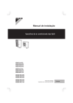
Figure 1: Functional block diagram of personal locating device
5.2
AIS transmission characteristics
The AIS Tx transmits using modified SOTDMA on two channels AIS1 and AIS2. The GNSS receiver, e.g. a GPS
receiver, determines the current position of the locating device and facilitates TDMA synchronization in the UTC direct
mode.
The locating device shall shutdown automatically if, under a fault condition, the transmitter remains permanently keyed
for more than 2 seconds. This shutdown shall be independent of the operating software.
5.2.1
AIS messages
The locating device shall broadcast Message 1 and Message 14, as defined in Recommendation ITU-R M.1371-5 [1].
The content of the messages differs for active transmissions (active mode) and test transmissions (test mode). The
combination of these messages in burst sequences is detailed in annex B.
ETSI
14
5.2.1.1
Final draft ETSI EN 303 098-1 V1.2.1 (2014-06)
Active mode
For Message 1 the Navigational status shall be set to "14". For message 14 the safety related text shall be set to "MOB
ACTIVE" (see clause B.1 for details).
5.2.1.2
Test mode
For Message 1 the Navigational status shall be set to "15". For message 14 the safety related text shall be set to "MOB
TEST" (see clause B.2 for details).
5.2.2
Synchronization
In UTC direct mode the locating device determines slot timing using the UTC timing signal from the GNSS.
The TDMA timing error shall be less than ±312 μs.
The position of the locating device shall be determined at least every minute once a GNSS position fix has been
obtained.
5.2.2.1
Active mode
The locating device shall start transmitting as soon as a position fix, SOG, COG and UTC lock are available or
60 seconds after activation if not. Optionally the locating device may also transmit unsynchronized using default
settings (see clause B.3 for details), within a period from 10 to 30 seconds after activation. This initial transmission is
intended to inform the local vessel that an MOB incident has occurred and allow the position of the vessel to be
recorded at that time.
NOTE:
In the present document, the terms "UTC lock" and "position fix" are used independently. It is however
recognized that in practice it is unlikely that a position fix can be obtained without UTC lock and
visa-versa.
The locating device shall begin synchronized transmission with the correct GNSS position within 5 minutes under
normal operating conditions
The locating device shall continue transmission even if the position and UTC lock from the positioning system is
subsequently lost or fails. The locating device shall maintain, as best it can, proper timing internally if UTC lock is lost.
If a position fix is lost, the locating device shall continue to transmit with the last known good position (see clause B.3).
5.2.2.2
Test mode
A single test message burst (see clause B.2) shall be transmitted as soon as a position fix, SOG, COG and time are
available. The device shall transmit when UTC lock is available so that SOTDMA is properly synchronized even if the
UTC parameters are invalid or out of date. If UTC lock is not available after five minutes the device shall abandon the
test mode without transmitting. If the UTC parameters are invalid or out of data the test shall be extended until valid
UTC parameters have been downloaded although no further transmission shall be attempted.
Activation of the test facility shall reset automatically after transmission of the burst.
5.2.3
GNSS position source
The GNSS compliant receiver shall meet the following requirements of EN 61108 series (GPS [4], GLONASS [5] or
Galileo [6]): position accuracy, acquisition, re-acquisition, receiver sensitivity, RF dynamic range, position update,
effects of specific interference signals but with a minimum update rate of once per minute, provide a resolution of one
ten thousandth of a minute of arc and uses the WGS-84 datum.
NOTE:
Galileo uses Galileo Terrestrial Reference Frame System (GTRF) datum which is a realization of the
International Terrestrial Reference Frame (ITRF) system and differs from WGS-84 by less than 5 cm
worldwide. GLONASS uses the Parametry Zemli 1990 (PZ-90) datum. As of September 17, 2007 the
PZ-90 datum has been updated to differ from WGS-84 by less than 40 cm worldwide.
ETSI
15
Final draft ETSI EN 303 098-1 V1.2.1 (2014-06)
The manufacturer shall provide evidence that an internal GNSS device cold start is forced at every AIS-MOB activation
(cold start refers to the absence of time dependent or position dependent data in memory, which might affect the
acquisition of the GNSS position).
5.2.3.1
UTC
All AIS equipment uses UTC for synchronizing transmissions. The version of UTC transmitted by both GPS and
Galileo, is not perturbed by leap seconds so that GPS time as of January 2013 is ahead of UTC by 16 seconds. The
version of UTC transmitted by GLONASS does apply leap seconds and remains synchronized to UTC albeit offset by
3 hours. Both GPS and Galileo transmit the timing offset that is applied by the GNSS receiver when computing UTC.
AIS SOTDMA relies on the correct and timely computation of UTC to determine slot timings accurately. Since the AIS
slot structure repeats every two seconds, the incorrect application of a leap second when determining UTC will result in
AIS transmissions beginning in the middle of a time slot rather than at the beginning of the time slot. Care shall be
taken when designing with multi-system GNSS receivers that UTC is correctly determined across satellite systems.
Since the equipment is required to do a GNSS cold start and to transmit its first valid position within 5 minutes of
activation for GPS and Galileo GNSS receivers the equipment may maintain a stored copy of the UTC parameters leap
second information.
5.2.3.2
UTC parameters storage
Where manufacturers do provide a mechanism whereby the stored copy of the UTC parameters (that is leap second
offset and predictions) can be kept up to date, then the GNSS cold start shall not make use of any stored information
other than valid leap second information.
5.2.4
Required settings
The locating device shall operate on dual channels, AIS1 and AIS2, in the VHF Maritime Mobile Service band. Tables 1, 2
and 3 are derived from Recommendation ITU-R M.1371-5 [1] and give the parameters required for an AIS locating
device.
Table 1: Required parameter settings
Symbol
PH.AIS1
PH.AIS2
PH.BR
PH.TS
PH.TST
NOTE:
Parameter name
Channel 1 (default channel 1)
Channel 2 (default channel 2)
Bit rate
Training sequence
Transmitter settling time (Transmit power within 20 % of final value.
Frequency stable to within ± 1,0 kHz of final value). Tested at
manufacturers declared transmit power.
Ramp down time
Transmission duration
Transmitter output power
600 mW ERP ≈ 1W EIRP.
Table 2: Required settings of physical layer constants
Symbol
PH.DE
PH.FEC
PH.IL
PH.BS
PH.MOD
Parameter name
Data encoding
Forward error correction
Interleaving
Bit scrambling
Modulation
ETSI
Value
NRZI
Not used
Not used
Not used
Bandwidth adapted GMSK
Setting
161,975 MHz
162,025 MHz
9 600 bps
24 bits
≤ 1,0 ms
≤ 832 μs
≤ 26,6 ms
600 mW ERP
16
Final draft ETSI EN 303 098-1 V1.2.1 (2014-06)
Table 3: Modulation parameters of the physical layer
Symbol
PH.TXBT
PH.MI
5.2.5
Name
Transmit BT-product
Modulation index
Value
0,4
0,5
Minimum transmitter performance characteristics
The technical characteristics as specified in table 4 shall apply to the transmitter.
Table 4: Minimum required transmitter characteristics
Transmitter parameters
Carrier power
Carrier frequency error
Slotted modulation mask
Transmitter test sequence and
modulation
Accuracy
Transmitter output power versus time
Spurious emissions
5.2.6
Requirements
nominal radiated power 600 mW ERP ±3 dB
±500 Hz (normal), ±1 000 Hz (extreme)
-20 dBc ∆fc > ±10 kHz
-40 dBc ± 25 kHz < ∆fc < ±62,5 kHz
see figure 4 in clause 8.4
< 3 400 Hz for Bit 0, 1 (normal and extreme)
2 400 Hz ± 480 Hz for Bit 2, 3 (normal and extreme)
2 400 Hz ± 240 Hz for Bit 4 ... 31 (normal, 2 400 + 480 Hz
extreme)
For Bits Bit 32 …199
1 740 ± 175 Hz (normal, 1 740 + 350 Hz extreme) for a bit
pattern of 0101
2 400 Hz ± 240 Hz (normal, 2 400 + 350 Hz extreme) for a bit
pattern of 00001111
Power within mask shown in figure 5 and timings given in
table 8 in clause 8.5
maximum 25 μW between 108 MHz to 137 MHz, 156 MHz to
161,5 MHz, and 1 525 MHz to 1 610 MHz
VHF Data Link (VDL) Access
The locating device shall use modified SOTDMA for the transmission of message bursts (annex B).
The locating device shall determine its own schedule for transmission of its messages based on random selection of the
first slot of the first burst. The other 7 slots within the first burst shall be fixed with reference to the first slot of the
burst. The increment between transmission slots within a burst shall be 75 slots and the transmissions shall alternate
between channels AIS1 and AIS2.
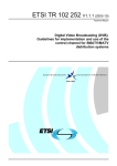
5.2.6.1
Active mode
In active mode (see figure 2), the locating device shall set a slot-time-out = 7 in the Communication state of all Message
1 transmissions in the first burst, and thereafter the slot time-out shall be decreased according to the rules of SOTDMA
in Recommendation ITU-R M.1371-5 [1]. Since the locating device does not have an AIS receiver, all slots shall be
regarded as candidates in the selection process. When time out occurs, the offset to the next set of 8 bursts is randomly
selected at 1 minute ±6 s.
ETSI
17
Final draft ETSI EN 303 098-1 V1.2.1 (2014-06)
Figure 2: Burst transmissions in active mode
All slot-time-out values of the Communication state of all Message 1 transmissions within every burst shall be the
same.
Two Message 14 shall be transmitted every 4th minute one on each channel, starting in the first minute
(i.e. slot-time-out = 7 and 3), and shall be the 5th and 6th message in the burst (see clause B.1).
Message 14 shall be transmitted alternately on AIS1 and AIS2.
5.2.6.2
Test mode
In test mode the locating device shall set a slot-time-out = 0 and sub-message = 0 in the Communication state of all
Message 1 transmissions in the first and only burst.
All slot time-out values of the Communication state of all Message 1 transmissions within every burst shall be the same.
Two Message 14 shall be transmitted one on each channel, and shall be the 1st and 8th message in the burst (see
clause B.2).
6
General conditions of measurement
6.1
Conformity testing
For the purpose of conformity testing clauses 6.2 to 6.5 shall apply.
6.2
Test Frequencies
Where radiated measurements are not performed in an anechoic chamber alternative channels other than the default
channels for AIS1 and AIS2 may be used during testing to avoid interference with live maritime systems. Where
alternative channels are used the alternative channels used shall be of the same separation (50 KHz apart) and within
±1 % of 162 MHz.
6.3
Identifier (user ID)
The manufacturer ID xx = 00 is reserved for testing purposes. The identifier used during testing to the present document
shall be in the format 97200yyyy.
6.4
Artificial Antenna
Where applicable, tests shall be carried out using an artificial antenna which shall be a substantially non-reactive
non-radiating load connected to the antenna connector. The Voltage Standing Wave Ratio (VSWR) at the 50 Ω
connector or the provider's specified test fixture shall not be greater than 1,5:1 over the frequency range of the
measurement.
ETSI
18
Final draft ETSI EN 303 098-1 V1.2.1 (2014-06)
In the case of integral antenna equipment, if the equipment does not have an internal permanent 50 Ω connector then it
is permitted to supply a second sample of the equipment with a temporary 50 Ω antenna cable and connector fitted to
facilitate testing.
6.5
Test signals
The manufacturer shall supply with the submitted samples a method for producing the following test transmission
signals. In addition, for some tests, is shall be possible to operate the samples in a continuous unmodulated transmission
(CW) mode.
NOTE:
6.5.1
Transmitters may have limitations concerning their maximum continuous transmit time and/or their
transmission duty cycle. It is intended that such limitations are respected during testing.
Standard test signal number 1
A series of reversals 010101… transmitted as all the bits within an AIS message frame, including header, start flag, end
flag and CRC. NRZI is not applied to the reversals or CRC (Cyclic Redundancy Check), i.e. unaltered "On Air" data.
The RF should be ramped up and down on either end of the AIS message frame.
6.5.2
Standard test signal number 2
A series of 00001111… repeated as the data within an AIS message frame, including header, start flag, end flag and
CRC. NRZI is not applied to the data or CRC. The RF should be ramped up and down on either end of the AIS message
frame.
6.5.3
Standard test signal number 3
A 511-bit pseudo random sequence as specified in Recommendation ITU-T O.153 [7] shall be used as the data within
an AIS message frame with header, start flag, end flag and CRC. NRZI is not applied to the pseudo random sequence or
CRC. The RF should be ramped up and down on either end of the AIS message frame.
6.5.4
Reference timing signal
For the timing tests in clauses 8.5, 8.6 and 8.7 the manufacturer shall supply a sample that produces an edge trigger
timing signal corresponding to T0 in figure 5 of clause 8.5.
6.6
Measurement uncertainty and interpretation of the
measured results
6.6.1
Measurement uncertainty
Absolute measurement uncertainties (maximum values) are specified in table 5.
Table 5: Absolute measurement uncertainties: maximum values
Parameter
RF frequency
Radiated emission of transmitter below 1 GHz
Radiated emission of transmitter above 1 GHz
Conducted RF power variations using a test fixture
Transmitter attack time
Transmitter release time
ETSI
Maximum uncertainty
±1 x 10⁻⁷
±4 dB
±6 dB
±0,75 dB
±20 %
±20 %
19
6.6.2
Final draft ETSI EN 303 098-1 V1.2.1 (2014-06)
Interpretation of the measurement results
The interpretation of the results recorded in a test report for the measurements described in the present document shall
be as follows:
•
the measured value related to the corresponding limit will be used to decide whether an equipment meets the
requirements of the present document;
•
the value of the measurement uncertainty for the measurement of each parameter shall be included in the test
report;
•
the recorded value of the measurement uncertainty shall be, for each measurement, equal to or lower than the
figures in table 5.
For the test methods, according to the present document, the measurement uncertainty figures shall be calculated in
accordance with TR 100 028 [2] and shall correspond to an expansion factor (coverage factor) k = 1,96 or k = 2 (which
provide confidence levels of respectively 95 % and 95,45 % in the case where the distributions characterizing the actual
measurement uncertainties are normal (Gaussian)).
Table 5 is based on such expansion factors.
6.7
Test conditions power sources and ambient temperatures
6.7.1
Normal and extreme test conditions
Conformity testing shall be carried out under normal test conditions (clause 6.8) and also where stated under extreme test
conditions (clauses 6.9.1 and 6.9.2 applied simultaneously).
6.7.2
Test power source
Where stated, the battery of the equipment shall be replaced by a test power source capable of producing normal
(clause 6.8.2) and extreme test voltages as specified in clauses 6.9.2.1 and 6.9.2.2.
6.8
Normal test conditions
6.8.1
Normal temperature and humidity
Normal temperature and humidity conditions for tests shall be any convenient combination of temperature and humidity,
within the following ranges:
•
Temperature:
+15 °C to +35 °C.
•
Relative humidity:
20 % to 75 %.
6.8.2
Normal test voltage
The normal test voltage shall be determined in each case and shall be the voltage corresponding to the voltage that a fresh
battery gives at normal temperature and humidity at a load equal to that of the equipment when activated.
6.9
Extreme test conditions
6.9.1
Extreme temperatures
For tests at extreme temperatures, measurements shall be made in accordance with the procedure specified in clause 6.9.1.1
at the lower and upper temperatures of -20 °C and +55 °C respectively except when installed within other equipment
subject to more stringent temperature requirements, in which case the more stringent requirements shall apply.
ETSI
20
6.9.1.1
Final draft ETSI EN 303 098-1 V1.2.1 (2014-06)
Procedure for tests at extreme temperatures
The equipment shall be switched off during the temperature stabilization period.
Before tests are carried out, the equipment shall have obtained thermal balance in the test chamber and have been
activated for a period of 5 minutes.
The location of the equipment under test in the climatic chamber shall not substantially influence the power output or
the power consumption of the equipment under test.
6.9.2
6.9.2.1
Extreme test voltages
Upper extreme test voltage
The upper extreme test voltage shall be determined in each case and shall be the voltage corresponding to the voltage that a
fresh battery gives at the upper extreme temperature with a load equal to that of the equipment when activated.
6.9.2.2
Lower extreme test voltage
The lower extreme test voltage shall be determined in each case. The equipment fitted with a primary battery shall be
placed in a climatic chamber and cooled to -20 °C allowing a stabilization period of 2 hours. The equipment shall then be
activated for a period of 6 hours. After this period the battery voltage shall be measured. This voltage shall be taken as the
lower extreme test voltage and shall be measured before disconnecting the battery.
7
Environmental tests
7.1
Introduction
The requirements of this clause demonstrate that the equipment is capable of continuous operation under the conditions of
various sea states, vibration, humidity and change of temperature likely to be experienced on a ship in which it is carried.
7.2
Procedure
Environmental tests shall be carried out before tests in respect of the other requirements in the present document are
performed on the same EUT. Environmental tests may be carried out in any order but the test specified in clause 7.13 shall
always be carried out last so as to detect any damage to EUT's water seals caused by the other environmental tests.
7.3
Performance check
The term performance check as used in the present document shall be that of activating the locating device in test mode
with GNSS data available, and checking the reception of Message 1 and Message 14 using a suitable AIS receiver.
The performance check shall be carried out only under normal test conditions as detailed in clause 6.8.1 unless
otherwise stated.
7.4
Drop test
7.4.1
Definition
The immunity against the effects of dropping is the ability of the equipment to maintain the specified mechanical and
electrical performance after being subjected to a series of drops onto a hard wooden test surface and into water.
ETSI
21
7.4.2
Final draft ETSI EN 303 098-1 V1.2.1 (2014-06)
Test conditions
During the test, the equipment shall be fitted with a suitable set of batteries and antenna but it shall be switched off. The
test shall be carried out under normal temperature and humidity conditions as detailed in clause 6.8.1.
The hard wooden test surface shall consist of a piece of solid hard wood with a minimum thickness of 15 cm and a mass of
at least 30 kilograms.
A container of calm sea water shall be used as the other surface.
The height of the lowest part of the equipment under test, relative to the test surface at the moment of release, shall be:
(i)
For drops onto the wooden test surface - 1 m.
(ii)
For drops onto the water - 20 m.
Equipment shall be subjected to this test in the configuration as it is normally used in operational circumstances.
7.4.3
Method of measurement
Equipment that can be armed shall be armed before testing (see clause 4.2).
For drop into water the test shall consist of a single drop test, and the test shall be performed on the EUT complete with
any detachable shock absorbers, which are normally part of it (e.g. a life vest).
For drops on the wooden surface the test shall consist of six drops, once on each face, and the test shall be performed on
the EUT alone excluding detachable shock absorbers.
7.4.4
Requirements
After the drops have been completed the equipment shall be inspected visually for signs of damage. Inspection for
mechanical damage, both internal and external, shall be carried out. Any damage shall not impair the operation of the
equipment. In particular, parts like knobs, switches and the antenna shall operate in the normal manner. For devices
without a water immersion sensor the act of dropping shall not cause the equipment to activate. For devices with a water
immersion sensor the act of dropping onto the wooden test surface shall not cause the equipment to activate, whereas
drops into water shall always cause the equipment to activate.
The requirement for the performance check (clause 7.3) shall also be met.
7.5
Temperature tests
7.5.1
Definition
The immunity against the effects of temperature is the ability of the equipment to maintain the specified mechanical and
electrical performance after the following tests have been carried out.
The maximum rate of raising or reducing the temperature of the chamber in which the equipment is being tested shall
be 1 °C/minute.
7.5.2
7.5.2.1
Dry heat test
Method of measurement
The equipment shall be placed in a chamber at normal temperature. The temperature shall then be raised to, and maintained
at, +70 °C (±3 °C) for a period of at least 10 hours. After this period any climatic control device provided in the equipment
may be switched on and the chamber cooled to +55 °C (±3 °C). The cooling of the chamber shall be completed within
30 minutes.
At the end of this period the EUT shall be subjected to the performance check.
ETSI
22
Final draft ETSI EN 303 098-1 V1.2.1 (2014-06)
The temperature shall then be maintained at +55 °C (±3 °C) for a period of 10 hours to 16 hours.
At the end of this period the EUT shall again be subjected to the performance check. The temperature of the chamber shall
be maintained at +55 °C (±3 °C) during the whole of the performance check periods.
At the end of the test, the EUT shall be returned to normal environmental conditions or to those at the start of the next test.
7.5.2.2
Requirements
The test shall not cause the equipment to activate or operate spuriously.
The requirement for the performance check (clause 7.3) shall also be met.
7.5.3
7.5.3.1
Damp heat test
Method of measurement
The EUT shall be placed in a chamber at normal room temperature and relative humidity. The temperature shall then be
raised to +40 °C (±2 °C), and the relative humidity raised to 93 % (±3 %) over a period of 3 hours ± 0,5 hours. These
conditions shall be maintained for a period of 10 hours to 16 hours.
The EUT shall be switched on 30 minutes later, or after such period as agreed with the manufacturer, and shall be kept
operational for at least 2 hours during which period the EUT shall be subjected to the performance check. The temperature
and relative humidity of the chamber shall be maintained as specified during the whole test period.
At the end of the test period and with the EUT still in the chamber, the chamber shall be brought to room temperature in not
less than 1 hour. At the end of the test the EUT shall be returned to normal environmental conditions or to those required at
the start of the next test.
7.5.3.2
Requirements
The test shall not cause the equipment to activate or operate spuriously.
The requirement for the performance check (clause 7.3) shall also be met.
7.5.4
7.5.4.1
Low temperature test
Method of measurement
The equipment shall be placed in a chamber at normal room temperature. Then the temperature shall be reduced to and
maintained at -30 °C (±3 °C) for a period of at least 10 hours. Any climatic devices provided within the equipment may then
be switched on and the chamber shall be warmed to -20 °C (±3 °C). The warming of the chamber shall be completed within
30 minutes (±5 minutes).
At the end of this period the EUT shall be subjected to the performance check.
The temperature shall then be maintained at -20 °C (±3 °C) for a period of 10 hours to 16 hours.
At the end of this period the EUT shall again be subjected to the performance check. The temperature of the chamber shall
be maintained at -20 °C (±3 °C) during the whole of the performance check periods.
7.5.4.2
Requirements
The test shall not cause the equipment to activate or operate spuriously.
The requirement for the performance check (clause 7.3) shall also be met.
ETSI
23
7.5.5
7.5.5.1
Final draft ETSI EN 303 098-1 V1.2.1 (2014-06)
Low temperature battery endurance test
Method of measurement
Using a fresh battery, the equipment shall be activated (at the ambient temperature) for a period of time as stated by the
manufacturer to be equivalent to the loss of battery capacity due to selftesting, stand-by loads as well as battery selfdischarge during the useful life of the battery (as defined in clause 4.7.1).
Alternatively the manufacturer may precondition a fresh battery by another means to achieve the same level of
discharge as defined in clause 4.7.1, the method shall be recorded in the test report.
The equipment shall then be placed in a chamber at normal room temperature. Then the temperature shall be reduced to
and maintained at -20 °C ± 3 °C for a period of 10 h to 16 h. Any climatic control device provided in the equipment
may be switched on at the conclusion of this period. The equipment shall be activated and the transmissions of the
equipment during the test shall be verified for a period of 12 h. The temperature of the chamber shall be maintained as
specified above for the whole of the period of 12 h. At the end of the test the EUT shall be returned to normal
environmental conditions.
7.5.5.2
Requirements
The equipment shall remain activated and transmitting for a minimum of 12 hours.
Following the test the requirement for the performance check (clause 7.3) shall also be met.
7.6
Vibration test
7.6.1
Definition
The immunity against the effects of vibration is the ability of the equipment to maintain the specified mechanical and
electrical performance when the following test is carried out.
7.6.2
Method of measurement
Equipment that can be armed shall be armed before testing (see clause 4.2).
The equipment, complete with any detachable shock absorbers that are normally part of it (e.g. a life vest), shall be
clamped to the vibration table by its normal means of support and in its normal attitude.
The equipment may be suspended to compensate for weight not capable of being withstood by the vibration table.
Provisions may be made to reduce or nullify any adverse effect on the equipment performance which may be caused by
the presence of any electro-magnetic fields from the vibration table.
Taking at least 15 minutes to cover each octave of frequency, the equipment shall be subjected to sinusoidal vertical
vibration at all frequencies between:
-
2 Hz or 5 Hz up to 13,2 Hz with an excursion of ±1 mm ± 10 %;
-
13,2 Hz up to 100 Hz with a constant maximum acceleration of 7 m/s/s.
A resonance search shall be carried out during the vibration test. If any resonance of the EUT has Q greater than
5 measured relative to the base of the vibration table, the EUT shall be subjected to a vibration endurance test at each
resonant frequency at the vibration level specified in the test with a duration of 2 h. If no resonance with Q greater than
5 occurs the endurance test shall be carried out at one single observed frequency. If no resonance occurs the endurance
test shall be carried out at a frequency of 30 Hz.
The test shall be repeated with vibration in each of the mutual perpendicular direction in the horizontal plane.
A performance check shall be carried out at least once during each endurance test period and once before the end of
each endurance test period.
ETSI
24
7.6.3
Final draft ETSI EN 303 098-1 V1.2.1 (2014-06)
Requirement
The test shall not cause the equipment to activate or operate spuriously.
The requirement for the performance check (clause 7.3) shall also be met. No damage or mechanical deterioration shall
be visible to the naked eye. The EUT if tested with a vibration absorber (e.g. a life jacket) shall not become detached.
7.7
Corrosion test
7.7.1
Definition
The immunity against the effects of corrosion is the ability of the equipment to maintain the specified mechanical and
electrical performance both during and after the following test has been carried out.
7.7.2
Method of measurement
Equipment that can be armed shall be armed before testing (see clause 4.2).
The equipment shall be placed in a chamber fitted with apparatus capable of spraying in the form of fine mist, such as
would be produced by a spray gun, salt solution to the formula in table 6.
Table 6: Salt solution formula
sodium chloride
26,5
magnesium chloride
2,5
magnesium sulphate
3,3
calcium chloride
1,1
potassium chloride
0,73
sodium bicarbonate
0,20
sodium bromide
0,28
plus distilled water to make the solution up to 1 l.
g
g
g
g
g
g
g
±10 %
±10 %
±10 %
±10 %
±10 %
±10 %
±10 %
Alternatively a 5 % sodium chloride (NaCl) solution may be used. The salt used for the test shall be high quality sodium
chloride (NaCl) containing, when dry, not more than 0,1 % sodium iodide and not more than 0,3 % of total impurities.
Salt solution concentration shall be 5 % (±1 %) by weight. The solution shall be prepared by dissolving 5 parts ±1 by
weight of salt in 95 parts by weight of distilled or de-mineralized water.
The pH value of the solution shall be between 6,5 and 7,2 at temperature of 20 °C (±2 °C). The pH value shall be
maintained within this range during conditioning. For this purpose, diluted hydrochloric acid or sodium hydroxide may
be used to adjust the pH value, provided that the concentration of NaCl remains within the prescribed limits. The pH
value shall be measured when preparing each new batch of solution.
The spraying apparatus shall be such that the products of corrosion cannot mix with the salt solution contained within
the spray reservoir.
The equipment shall be sprayed simultaneously on all its external surfaces with the salt solution for a period of 1 hour.
This spraying shall be carried out 4 times with a storage period of 7 days; at 40 °C (±2 °C) after each spraying. The
relative humidity during storage shall be maintained between 90 % and 95 %.
At the end of the total period the equipment shall be examined visually.
7.7.3
Requirements
The test shall not cause the equipment to activate or operate spuriously.
There shall be no undue deterioration or corrosion of the metal parts, finishes, material, or component parts visible to
the naked eye.
In the case of hermetically sealed equipment there shall be no evidence of moisture penetration.
ETSI
25
7.8
Thermal shock test
7.8.1
Definition
Final draft ETSI EN 303 098-1 V1.2.1 (2014-06)
The immunity against the effects of thermal shock is the ability of the equipment to maintain the specified mechanical
and electrical performance after the following test has been carried out.
7.8.2
Method of measurement
The equipment shall be operational but not armed before testing (see clause 4.2).
The equipment shall be placed in an atmosphere of +70 °C (±3 °C) for 1 hour. It shall then be immersed in water at
+25 °C (±3 °C) to a depth of 10 cm, measured from the highest point of the equipment to the surface of the water, for a
period of 1 hour.
7.8.3
Requirements
The test shall not cause the equipment to activate or operate spuriously.
The requirement for the performance check (clause 7.3) shall also be met. No damage shall be visible to the naked eye
and the equipment shall not show any sign of significant external damage or harmful penetration of water.
7.9
Buoyancy test
7.9.1
Definition
Buoyancy, expressed as a percentage, is its buoyant force divided by its gravity force.
7.9.2
Method of measurement
The equipment shall be operational but disarmed before testing (see clause 4.2).
For Category 1 equipment the locating device shall be submerged in calm fresh water.
For Category 2 equipment the locating device and its buoyancy device shall be submerged in calm fresh water.
One of the following methods of measurement shall be used:
•
the buoyant force shall be measured when the locating device is totally submerged in fresh water. The buoyant
force shall be then divided by the measured gravity force. The result shall be recorded; or
•
the buoyancy may be calculated by dividing the volume of the unit above the waterline by the total volume of
the locating device. The result shall be recorded.
7.9.3
Requirements
The test shall not cause the equipment to activate or operate spuriously.
The value of buoyancy shall be at least 5 %.
ETSI
26
7.10
Compass safe distance test
7.10.1
Definition
Final draft ETSI EN 303 098-1 V1.2.1 (2014-06)
The compass safe distance is the closest distance to compasses or compass sensors (flux gate, magnetometer) at which
the locating device is safe to be stored.
The compass-safe distance Dmin is defined as the distance between the nearest point of the locating device and the
centre of the compass or magnetometer at which it will just produce a deviation in the measurement compass or
compass sensor of X°/H where:
•
X is 5,4° for the standard compass and 18° for the steering compass, the standby steering compass and the
emergency compass.
•
H is the horizontal component of the magnetic flux density in μT of the earth's Geomagnetic field at the place
of testing.
7.10.2
Method of measurement
Equipment that can be armed shall be armed before testing (see clause 4.2).
The equipment shall be tested in the position and attitude relative to the compass or compass sensor at which the error
produced at the compass would be a maximum (figure 3).
Figure 3: Compass safe distance test set up
Steps should be taken to ensure the Geomagnetic field at the test site is uniform.
With the EUT removed from the test side the measurement compass or compass sensor is aligned with magnetic north
so that the measured deflection is 0°.
The equipment to be tested (EUT) is then placed in the same plane and on an east west line passing through the centre
of the measurement compass or compass sensor. The measurement compass or compass sensor remains stationary and
the EUT is moved along the line until the required deflection X°/H is observed. At this position the EUT is re-oriented
until the deflection is maximized. The EUT is then moved again along the east west line until the required deflection
X°/H is again observed. The distance Dmin between the centre of the measurement compass or compass sensor and the
nearest point of the EUT is recorded.
7.10.3
Requirements
The minimum distance to obtain the required deflection Dmin shall be recorded in the test report.
ETSI
27
7.11
Final draft ETSI EN 303 098-1 V1.2.1 (2014-06)
Solar radiation test
This test need not be carried out if the manufacturer produces sufficient evidence that the components, materials, etc.
maintain their specified mechanical and electrical performance against the effects of continuous solar radiation.
7.11.1
Definition
The immunity against the effects of continuous solar radiation is the ability of the equipment to maintain the specified
mechanical and electrical performance after the following test has been carried out.
7.11.2
Method of measurement
Equipment that can be armed shall be armed before testing (see clause 4.2).
The equipment shall be placed on a suitable support and exposed continuously to a simulated solar radiation source
(table 7) for 80 hours.
The intensity at the test point, which shall also include any radiation reflected from the test enclosure, shall be
1 120 W/m2 ± 10 % with a spectral distribution given in table 7.
Table 7: Spectral distribution
Spectral Region Ultra-violet B Ultra-violet A
Visible
Bandwidth
0,28 to 0,32
0,32 to 0,40
0,40 to 0,52 0,52 to 0,64 0,64 to 0,78
{μm}
Radiance
5
63
200
186
174
2
{W/m }
Tolerance
±35
±25
±10
±10
±10
{%}
NOTE:
Radiation shorter than 0,30 μm reaching the earth's surface is insignificant.
7.11.3
Infra-red
0,78 to 3,00
492
±10
Requirements
The test shall not cause the equipment to activate or operate spuriously.
No damage shall be visible to the naked eye and the equipment shall not show any sign of significant external damage.
7.12
Oil resistance test
This test need not be carried out if the manufacturer produces sufficient evidence that the components, materials, etc.
maintain their specified mechanical and electrical performance against the effects of corrosion.
7.12.1
Definition
The immunity against the effects of immersion in mineral oil is the ability of the equipment to maintain the specified
mechanical and electrical performance after the following test has been carried out.
7.12.2
Method of measurement
Equipment that can be armed shall be armed before testing (see clause 4.2).
The equipment shall be immersed horizontally for a period of 24 hours under a 100 mm head of mineral oil as specified
below at normal room temperature.
-
aniline point:
120 °C;
-
flash point:
minimum 240 °C;
-
viscosity:
10 - 25 cSt at 99 °C.
ETSI
28
Final draft ETSI EN 303 098-1 V1.2.1 (2014-06)
The following oils may be used:
-
ASTM Oil No. 1;
-
ASTM Oil No. 5;
-
ISO Oil No. 1.
7.12.3
Requirements
The test shall not cause the equipment to activate or operate spuriously.
No sign of damage such as shrinking, cracking, swelling, dissolution or change of mechanical qualities of the
equipment, including labelling, shall be visible to the naked eye.
7.13
Protection of the transmitter
7.13.1
Definition
When operating, the locating device transmitter shall not be damaged due to antenna mismatching and shall remain
water-tight.
7.13.2
Method of measurement
This test shall be carried out on the same sample of the equipment used for testing to, and after all the preceding tests in
clause 7 have been carried out.
With the transmitter operating, the equipment shall be completely immersed in water to a depth of 1 m for a period of
5 minutes. For equipment fitted with an extendible antenna, the test shall be carried out with the antenna fully extended,
and repeated with the antenna fully retracted under normal test conditions.
Saline solution of normal sea saltiness (see corrosion test in clause 7.7) shall be used.
7.13.3
Requirement
The test shall not cause the equipment to deactivate or operate spuriously.
No damage shall be visible to the naked eye and the equipment shall not show any sign of significant external damage
or harmful penetration of water, and the requirements of the performance check (clause 7.3) shall also be met.
8
Tests on the AIS transmitter
8.1
Frequency error
8.1.1
Definition
The frequency error of the transmitter is the difference between the measured carrier frequency in the absence of
modulation and its required frequencies AIS1 and AIS2.
8.1.2
Method of measurement
The carrier frequency shall be measured with the equipment placed in the test fixture (see clause 6.4). The measurement
shall be made using the test power source (see clause 6.7.2) under both normal and extreme test conditions. The carrier
frequency shall be measured in the absence of modulation. The test shall be performed on AIS1 and AIS2.
ETSI
29
8.1.3
Final draft ETSI EN 303 098-1 V1.2.1 (2014-06)
Limit
The frequency error under normal conditions shall not exceed ±500 Hz, and under extreme test conditions shall not
exceed ±1 kHz.
8.2
Conducted Power
The purpose of this test is to verify that the output power from the locating device is within limits at extreme operating
temperatures.
Note that the conducted power delivered to an artificial antenna is likely to be greater than the measured ERP
(clause 8.3) due to absorption by the salty man support (see clause A.4).
8.2.1
Definition
This is the average or mean power delivered to the artificial antenna (see clause 6.4) in the absence of modulation.
8.2.2
Method of measurement under normal test conditions
The transmitter shall be connected to an artificial antenna (see clause 6.4) and the average or mean power delivered to
this artificial antenna shall be measured under normal conditions (see clause 6.8), and at the extremes of temperature
(see clause 6.9.1).
A measurement for frequency AIS1 shall be made and repeated for AIS2.
The mean power under normal conditions PNorm shall be measured.
The mean power under extreme conditions P-20 and P+55 shall be measured.
The differences between the normal and extreme conditions shall be determined:
Pdiff1 = PNorm - P-20 and
8.2.3
Pdiff2 = PNorm - P+55
Limit
The difference between the conducted power under extreme conditions and the conducted power under normal
conditions shall be less than ±3 dB for both AIS1 and AIS2.
8.3
Maximum Effective Radiated Power (ERP)
8.3.1
Definition
The Effective Radiated Power (ERP) is the power radiated in the direction of the maximum field strength under the
specified conditions of measurements.
8.3.2
Method of measurement
The measurement is made under normal conditions (see clause 6.8) for frequency AIS1 and repeated for AIS2.
On a test site selected from annex A, the equipment shall be placed on the support and according to the requirements of
clause A.4. The transmitter shall be switched on to transmit continuously without modulation.
The receiver shall be tuned to the transmitter carrier frequency. The test antenna shall be orientated for vertical
polarization. The test antenna shall be raised or lowered through the specified range of heights until a maximum signal
level is detected on the measuring receiver.
The transmitter shall be rotated through 360° around a vertical axis in order to find the direction of the maximum signal.
ETSI
30
Final draft ETSI EN 303 098-1 V1.2.1 (2014-06)
The maximum signal level detected by the measuring receiver shall be recorded. For equipment tested using the support
described in clause A.4.2 only, the level detected at 90°, 180° and 270° from the maximum shall also be recorded
avoiding nulls where possible by movement of the receive antenna by no more than 10°.
The transmitter shall be replaced by a substitution antenna as defined in annex A.
The substitution antenna shall be connected to a calibrated signal generator.
The frequency of the calibrated signal generator shall be adjusted to the transmit carrier frequency.
The input attenuator setting of the measuring receiver shall be adjusted in order to increase the sensitivity of the
measuring receiver, if necessary.
The test antenna shall be raised or lowered through the specified range of heights to ensure that the maximum signal is
received.
The input signal to the substitution antenna shall be adjusted to the level that produces a level detected by the measuring
receiver that is equal to the level noted to that detected from the equipment under test corrected for the change in input
attenuator setting of the measuring receiver.
The maximum ERP is equal to the power supplied by the signal generator, increased by the gain of the substitution
antenna and corrected for the change in the attenuator.
8.3.3
Limits
For equipment tested using the support described in clause A.4.1. the maximum ERP shall be 600 mW ±3 dB.
For equipment tested using the support described in clause A.4.2. the average of the four measurements recorded shall
be 600 mW ±3 dB.
8.4
Transmitter spectrum mask
8.4.1
Definition
The transmitter spectrum mask defines the limits within the range fc ±75 kHz for the peak power of all modulated
signals including all side bands associated with the carrier.
8.4.2
Method of measurement
The transmitter shall be connected to an artificial antenna (see clause 6.4) with a means of measuring the power
delivered to the load. The equipment shall be operated from the test power source (clause 6.7.2). Standard test signal
number 3 (see clause 6.5.3) shall be used to modulate the transmitter in repeated packets.
The measurement shall be made under normal test conditions.
To determine the reference peak power and measure the emissions in the adjacent channels, the emission is suitably
applied to the input of a spectrum analyser with the following preferred settings:
•
Resolution bandwidth:
1 kHz;
•
Video bandwidth:
3 kHz;
•
Scan bandwidth:
150 kHz;
•
Centre frequency:
Carrier frequency AIS1 and AIS2;
•
Detector type:
Peak hold.
A sufficient number of sweeps shall be used and sufficient transmission packets measured to ensure that the emission
profile is fully developed. A reference carrier power shall be calculated as being the maximum power within the
frequency limits set in clause 8.1.3. The emission profile shall then be normalized so that the reference carrier power is
set to 0 dBc. The result is compared to the mask given in figure 4.
ETSI
31
Final draft ETSI EN 303 098-1 V1.2.1 (2014-06)
A measurement for frequency AIS1 shall be made and repeated for AIS2.
Figure 4: Transmitter spectrum mask
The mask is set as follows:
For ±10 kHz the limit is 0 dBc. From ±10 kHz to ±20 kHz the limit decreases linearly from -20 dBc to -40 dBc. From
±20 kHz to ±62,5 kHz the limit is -40 dBc.
8.4.3
Limit
The normalized emission profile shall not exceed the mask of figure 4.
8.5
Transmitter transient behaviour (output power)
8.5.1
Definition
The transient behaviour (output power) of the transmitter is determined by the time-dependency of the transmitter
power when the transmitter output power is switched on and off. Within the scope of the present document, only the
transmit power as a function of time is tested as shown in figure 5 and defined in table 8 where:
a)
transmitter delay time (TA - T0) is the time between the start of the slot and the moment when the transmit
power may exceed -50 dB of the steady-state power (PSS);
b)
transmitter attack time (TB2 - TA) is the time between the transmit power exceeding -50 dBc and the moment
when the transmit power maintains a level within +1,5 dB - 1 dB from PSS;
c)
transmitter release time (TF - TE) is the time between the end flag being transmitted and the moment when the
transmitter output power has reduced to a level 50 dB below PSS and remains below this level thereafter;
d)
transmission duration (TF - TA) is the time from when power exceeds -50 dBc to when the power returns to
and stays below -50 dBc.
ETSI
32
Final draft ETSI EN 303 098-1 V1.2.1 (2014-06)
Figure 5: Power versus time mask
Table 8: Definitions of timings
TB
Reference
Bit Periods
Time
(ms)
T0
0
0
TA
0 to 6
0 to 0,625
TB1
6
0,625
Power shall be within +1,5 or -3 dB of PSS
TB2
8
0,833
Power shall be within +1,5 or -1 dB of PSS
233
24,271
Power shall remain within +1,5 or -1 dB of PSS during the
period TB2 to TE (see note)
241
25,104
Power shall be ≤ -50 dB of PSS and stay below this
TE (includes 1 stuffing bit)
TF (includes 1 stuffing bit)
NOTE:
8.5.2
Definition
Start of transmission slot. Power shall NOT exceed -50 dB of
PSS before T0
TA = Point at which power exceeds -50 dB of PSS
TG
Start of next transmission time period
256
26,667
There shall be no modulation of the RF after the termination of transmission (TE) until the power has reached
zero and the next slot begins (TG).
Method of measurement
The measurement is made under normal conditions (see clause 6.7) for frequency AIS1 and repeated for AIS2.
The transmitter shall be connected to an artificial antenna (see clause 6.4). The measurement shall be carried out by
transmitting test signal number 1.
A spectrum analyser shall be used to make the measurements with the following preferred settings:
•
Resolution bandwidth:
1 MHz;
•
Video bandwidth:
1 MHz;
•
Scan bandwidth:
zero span;
ETSI
33
Final draft ETSI EN 303 098-1 V1.2.1 (2014-06)
•
Centre frequency:
Carrier frequency as measured in clause 8.1;
•
Detector type:
sample detector [single sweep mode].
The spectrum analyser shall be synchronized to the nominal start time of the slot (T0), which is provided by a modified
sample of the EUT submitted by the manufacturer (clause 6.5.4).
8.5.3
Limit
The transmitter power shall remain within the mask shown in figure 5 and associated timings given in table 8.
8.6
Transmitter Transient Behaviour (frequency deviation)
8.6.1
Definition
The transient behaviour (frequency deviation) of the transmitter is determined by the time-dependency of the frequency
deviation during the transmission of an AIS message.
A test to verify that the training sequence starts with a 0 and is a 0101 pattern of 24 bits. The peak frequency deviation
is derived from the baseband signal to verify modulation accuracy.
8.6.2
Method of measurement
The measurement is made under normal and extreme conditions (see clauses 6.7 and 6.8) for frequency AIS1 and
repeated for AIS2.
The transmitter shall be connected to an artificial antenna (see clause 6.4) comprising a power attenuator and a suitable
measuring device either option A or option B of figure 6.
Figure 6: Measurement arrangement for modulation accuracy
NOTE:
It is permissible to use data recovery filter between the test discriminator and the storage oscilloscope
provided that it has a bandwidth of at least 100 KHz.
The measuring device shall be synchronized to the nominal start time of the first preamble bit (TB), using the modified
sample of the EUT submitted by the manufacturer (clause 6.5.4). Using test signal 2 the delay from the T0 timing edge
provided by EUT (see clause 6.5.4) is adjusted until the centre position of the first data bit (bit 0) is determine as the
trigger point TB. Holding these settings test signal 2 is replaced with test signal 1 to confirm that TB has been correctly
determined.
ETSI
34
Final draft ETSI EN 303 098-1 V1.2.1 (2014-06)
The transmitter shall be modulated with test signal number 2.
The deviation from the carrier frequency shall be measured as a function of time.
The transmitter shall be modulated with test signal number 1.
The deviation from the carrier frequency shall be measured as a function of time.
8.6.3
Limit
In each case the observed training sequence shall begin with a '0'.
The peak frequency deviation at various points within the data frame shall comply with table 9. These limits apply to
both the positive and negative modulation peaks. Bit 0 is defined as the first bit of the training sequence.
Table 9: Peak frequency deviation versus time
Measurement period from
centre to centre of each bit
Bit 0 to bit 1
Bit 2 to bit 3
Bit 4 to bit 31
Bit 32 to bit 199
Test signal 1
Test signal 2
Normal
Extreme
Normal
Extreme
< 3 400 Hz
2 400 Hz ± 480 Hz
2 400 Hz
2 400 Hz
2 400 Hz
2 400 Hz
±240 Hz
±480 Hz
±240 Hz
±480 Hz
1 740 Hz
1 740 Hz
2 400 Hz
2 400 Hz
±175 Hz
±350 Hz
±240 Hz
±480 Hz
8.7
Synchronization accuracy
8.7.1
Definition
The synchronization accuracy defines the allowable time deviation including additive jitter in the transmission of an
AIS message from ideal SOTDMA timing. The synchronization accuracy test verifies:
(i)
that the EUT transmission will be properly synchronized once UTC lock is acquired;
(ii)
that following UTC lock the EUT will continue properly synchronized transmission if UTC lock is
subsequently lost.
This test requires analysis of the transmissions of the EUT in active mode. Care shall be taken to ensure that
transmissions are not received by a nearby AIS receiver such as a coastal shore station.
8.7.2
Method of measurement
The EUT shall be programmed with valid UTC parameters as described in the user documentation or shall be
precondition so as to have downloaded valid UTC parameters before the start of the test.
The measurement is made under normal and extreme conditions (see clauses 6.8 and 6.9) for frequency AIS1 and
repeated for AIS2.
The transmitter shall be connected to an artificial antenna (see clause 6.4). The EUT's GNSS receiver shall be connected
to a GNSS simulator simulating more than 3 satellites and that additionally provides a UTC output and a 1 pps
reference output with an accuracy of ±1 μs or better (figure 7).
ETSI
35
Final draft ETSI EN 303 098-1 V1.2.1 (2014-06)
Figure 7: Measurement arrangement for synchronization accuracy
1)
Activate the EUT in active mode with GNSS signal enabled and record transmissions for 40 minutes. After
40 minutes inhibit the GNSS signal and continue to record transmissions for a further 20 minutes.
2)
Operate the test facility on the EUT with GNSS signal enabled and record transmissions for 6 minutes.
3)
Operate the test facility on the EUT with GNSS signal inhibited and record transmissions for 6 minutes.
Whenever a transmission is recorded the associated timing difference between the EUT generated T0 (see clause 6.5.4)
edge and the GNSS simulator generated 1 pps reference shall also be recorded. The EUT may pick any one of 75 slots
in any two second period. The legitimate timings for both even and odd seconds are given in table 10.
Table 10: Legitimate T0 Timings (μs) in any second
Even
26 667
53 333
80 000
106 667
133 333
160 000
186 667
213 333
240 000
266 667
Odd
13 333
40 000
66 667
93 333
120 000
146 667
173 333
200 000
226 667
253 333
Even
293 333
320 000
346 667
373 333
400 000
426 667
453 333
480 000
506 667
533 333
Odd
280 000
306 667
333 333
360 000
386 667
413 333
440 000
466 667
493 333
520 000
Even
560 000
586 667
613 333
640 000
666 667
693 333
720 000
746 667
773 333
800 000
Odd
546 667
573 333
600 000
626 667
653 333
680 000
706 667
733 333
760 000
786 667
Even
826 667
853 333
880 000
906 667
933 333
960 000
986 667
-
Odd
813 333
840 000
866 667
893 333
920 000
946 667
973 333
-
The UTC output from the simulator is used by the timing measurement unit to determine when even or odd slot timing
measurements apply. The time difference between a legitimate slot start and the measured T0 shall be compared to the
limit of clause 8.7.2.
8.7.3
Limit
Verify that in case 8.7.2 (1) and (2) the EUT transmits a valid position within 5 minutes and that all transmissions with
a valid position have a synchronization error (including additive jitter) of less than ±312 μs.
Verify that in case 8.7.2 (1) Transmission synchronization error after 40 minutes may drift outside the limit of ±312 μs.
The absolute maximum value of the synchronization error after 40 minutes shall be recorded in the test report.
Verify that in cases 8.7.2 (3) the EUT does not transmit at all.
ETSI
36
8.8
Spurious emissions
8.8.1
Definition
Final draft ETSI EN 303 098-1 V1.2.1 (2014-06)
Emission(s) on a frequency or frequencies which are outside the necessary bandwidth and the level of which may be
reduced without affecting the corresponding transmission of information. Spurious emissions include harmonic emissions,
parasitic emissions, intermodulation products, and frequency conversion products, but exclude out-of-band emissions.
8.8.2
Method of measurement
Spurious emissions shall be measured using a test site described in annex A.
The measurement shall be performed with the locating device in its standard position (annex A) and according to the
requirements of clause A.4.
The method of measurement described in clause 8.3 shall be used to search for spurious emissions in the frequency
band 30 MHz to 2 GHz, excluding the frequency band tested in clause 8.4.
The measuring receiver shall have a bandwidth of 100 kHz to 120 kHz.
The measurement shall only be performed under normal test conditions (see clause 6.8), the locating device being
rotated until the maximum emission is detected. The measurement is also made when the locating device has been
activated but is not transmitting.
8.8.3
Limit
The power of any spurious emission component when transmitting shall not exceed 25 μW between 108 MHz to
137 MHz, 156 MHz to 161,5 MHz, and 1 525 MHz to 1 610 MHz.
The power of any spurious emission component when not transmitting (even when activated) shall not exceed 2 nW
between 30 MHz and 1 GHz and 20 nW between 1 GHz and 2 GHz.
9
VDL Link layer tests
9.1
Active mode tests
These tests require analysis of the transmissions of the EUT in active mode. Care shall be taken to ensure that
transmissions are not received by a nearby AIS receiver such as a coastal shore station.
9.1.1
Method of measurement
Activate the EUT in active mode and record transmissions for 40 minutes. Inhibit GNSS data and record transmissions
for a further 20 minutes.
Record the activation time of the EUT.
For all transmitted messages record:
•
transmission time (UTC);
•
transmission slot;
•
in-slot timing;
•
transmission channel;
•
message content.
The records will be evaluated in the following test items.
ETSI
37
9.1.2
Final draft ETSI EN 303 098-1 V1.2.1 (2014-06)
Initialization period - Required results
The following is required:
a)
The first message is transmitted within 60 seconds after activation.
b)
The first message with a valid position is transmitted within 5 minutes.
9.1.3
Message content of Message 1 - Required results
For position reports transmitted after 5 minutes and before 40 minutes the following is required:
a)
Message ID = 1.
b)
Repeat indicator = 0.
c)
User ID as configured in the EUT.
d)
Navigational status = 14.
e)
Rate of turn = default.
f)
SOG = actual SOG from GNSS receiver.
g)
Position accuracy = according to the RAIM result if provided, otherwise 0.
h)
Position = actual position from internal GNSS receiver.
i)
Position is updated at least once per minute, for each burst.
j)
COG = actual COG from internal GNSS receiver.
k)
True heading = default.
l)
Time stamp = actual UTC second (0...59).
m)
Verify correct indication according to manufacturer's documentation.
9.1.4
Message content of Message 14 - Required results
The following is required:
a)
Message ID = 14.
b)
Repeat indicator = 0.
c)
Source ID = as configured in the EUT.
d)
Text = "MOB ACTIVE".
9.1.5
Transmission schedule for Message 1 - Required results
For position reports transmitted after 15 minutes and before 40 minutes the following applies:
a)
Verify that the EUT has operated in sync mode 0 (UTC direct).
b)
The EUT transmits one burst of messages once per minute.
c)
The duration of a burst is 14 s.
d)
A burst consists of 8 messages.
e)
The transmissions in a burst are alternating between AIS1 and AIS2.
f)
Consecutive messages are 75 slots apart and on the other channel.
ETSI
38
Final draft ETSI EN 303 098-1 V1.2.1 (2014-06)
g)
The same set of slots is used in each burst for 8 minutes.
h)
A new set of slots is randomly selected after 8 minutes.
i)
The first slot of the new set of slots is within the interval of 1 m ± 6 seconds from the first slot of the previous
set of slots, that is the increment is randomly selected in the range 2 025 to 2 475 slots.
j)
The manufacturer is to provide documentation on how the increment is selected randomly.
9.1.6
Communication state of Message 1 - Required results
For position reports transmitted after 5 minutes and before 40 minutes the following applies:
a)
The SOTDMA communication state as defined for message 1 is used.
b)
The sync state = 0.
c)
The time-out starts with 7 for all messages of the first burst after a change in slots.
d)
The time-out value is decremented by 1 for each frame.
e)
The time-out value is reset to 7 after time-out = 0.
f)
The sub message for time-out 3,5,7 = number of received stations (0).
g)
The sub message for time-out 2,4,6 = slot number.
h)
The sub message for time-out 1 = UTC hour and minute.
i)
The sub message for time-out 0 = slot offset to the transmission slot in the next frame.
9.1.7
Transmission schedule of Message 14 - Required results
The following is required:
a)
Message 14 is transmitted every 4 minutes.
b)
The transmissions of Message 14 are alternating between AIS1 and AIS2.
c)
Message 14 is transmitted in a Message 1 slot, replacing the Message 1, on the channel for which the
Message 1 was scheduled.
d)
Message 14 did not replace a Message 1 with a time-out value = 0.
9.1.8
Transmission with lost GNSS - Required results
For position reports transmitted after 45 minutes the following applies:
a)
The EUT continues transmission.
b)
The same transmission schedule is used as with GNSS data available.
c)
Communication State Sync state = 3.
d)
SOG = last valid SOG.
e)
Position accuracy = low.
f)
Position = last valid position.
g)
COG = last valid COG.
h)
Time stamp = 62.
i)
RAIM-flag = 0.
ETSI
39
j)
9.2
Final draft ETSI EN 303 098-1 V1.2.1 (2014-06)
Verify correct indication as per manufacturer's documentation.
Test mode tests with GNSS data available
These tests require analysis of the transmissions of the EUT in test mode.
9.2.1
Method of measurement
Activate the EUT in test mode with GNSS data available and record transmissions.
9.2.2
Required results
The following is required:
a)
The EUT starts transmission after valid GNSS data is available.
b)
A single burst of 8 messages in the correct order and correctly populated as per clause B.2.
c)
User ID as configured in the EUT.
d)
Navigational status = 15 (not defined).
e)
SOG = actual SOG from GNSS receiver.
f)
Position accuracy = according to the RAIM result if provided, otherwise 0.
g)
Position = actual position from internal GNSS receiver.
h)
COG = actual COG from internal GNSS receiver.
i)
Time stamp = actual UTC second (0...59).
j)
The communication state time-out always = 0 with sub message = 0.
k)
The transmission of Messages 1 and 14 stops after one burst of 8 messages.
l)
The text message in Message 14 is "MOB TEST".
m)
Verify correct indication as per manufacturer's documentation.
9.3
Test mode tests without GNSS data available
These tests require analysis of the transmissions of the EUT in test mode.
9.3.1
Method of measurement
Activate the EUT in test mode with no GNSS data available and record transmissions.
9.3.2
Required results
The following is required:
a)
The EUT does not transmit within 5 minutes.
ETSI
40
Final draft ETSI EN 303 098-1 V1.2.1 (2014-06)
Annex A (normative):
Radiated measurements
A.1
Test sites and general arrangements for
measurements involving the use of radiated fields
This normative annex introduces three most commonly available test sites, an anechoic chamber, an anechoic chamber
with a ground plane and an Open Area Test Site (OATS), which may be used for radiated tests. These test sites are
generally referred to as free field test sites. Both absolute and relative measurements can be performed in these sites.
Where absolute measurements are to be carried out, the chamber should be verified. A detailed verification procedure is
described in TR 102 273, relevant parts 2, 3 and 4 [i.1].
NOTE:
A.1.1
To ensure reproducibility and traceability of radiated measurements only these test sites should be used in
test measurements.
Anechoic chamber
An anechoic chamber is an enclosure, usually shielded, whose internal walls, floor and ceiling are covered with radio
absorbing material, normally of the pyramidal urethane foam type. The chamber usually contains an antenna support at
one end and a turntable at the other. A typical anechoic chamber is shown in figure A.1.
Turntable
Test
antenna
Radio
absorbing
materia l
A ntenna support
A ntenna support
e
ng
Ra
3
gth
n
le
m
m
10
or
Figure A.1: A typical anechoic chamber
The chamber shielding and radio absorbing material work together to provide a controlled environment for testing
purposes. This type of test chamber attempts to simulate free space conditions.
ETSI
41
Final draft ETSI EN 303 098-1 V1.2.1 (2014-06)
The shielding provides a test space, with reduced levels of interference from ambient signals and other outside effects,
whilst the radio absorbing material minimizes unwanted reflections from the walls and ceiling which can influence the
measurements. In practice it is relatively easy for shielding to provide high levels (80 dB to 140 dB) of ambient
interference rejection, normally making ambient interference negligible.
A turntable is capable of rotation through 360° in the horizontal plane and it is used to support the test sample (EUT) at a
suitable height (e.g. 1 m) above the ground plane. The chamber shall be large enough to allow the measuring distance of at
least 3 m or 2(d1+d2)2/λ (m), whichever is greater (see clause A.2.5). The distance used in actual measurements shall be
recorded with the test results.
The anechoic chamber generally has several advantages over other test facilities. There is minimal ambient interference,
minimal floor, ceiling and wall reflections and it is independent of the weather. It does however have some
disadvantages which include limited measuring distance and limited lower frequency usage due to the size of the
pyramidal absorbers. To improve low frequency performance, a combination structure of ferrite tiles and urethane foam
absorbers is commonly used.
All types of emission, sensitivity and immunity testing can be carried out within an anechoic chamber without
limitation.
A.1.2
Anechoic chamber with a ground plane
An anechoic chamber with a ground plane is an enclosure, usually shielded, whose internal walls and ceiling are
covered with radio absorbing material, normally of the pyramidal urethane foam type. The floor, which is metallic, is
not covered and forms the ground plane. The chamber usually contains an antenna mast at one end and a turntable at the
other. A typical anechoic chamber with a ground plane is shown in figure A.2.
This type of test chamber attempts to simulate an ideal OATS whose primary characteristic is a perfectly conducting
ground plane of infinite extent.
Antenna
mast
Test
antenna
Radio
absorbing
material
1 m to 4 m
1,5 m
n
ou
Gr
e
lan
p
d
gth
len
e
ng
Ra
Turntable
o
3m
r 10
m
Figure A.2: A typical anechoic chamber with a ground plane
In this facility the ground plane creates the wanted reflection path, such that the signal received by the receiving antenna
is the sum of the signals from both the direct and reflected transmission paths. This creates a unique received signal
level for each height of the transmitting antenna (or EUT) and the receiving antenna above the ground plane.
ETSI
42
Final draft ETSI EN 303 098-1 V1.2.1 (2014-06)
The antenna mast provides a variable height facility (from 1 m to 4 m) so that the position of the test antenna can be
optimized for maximum coupled signal between antennas or between an EUT and the test antenna.
A turntable is capable of rotation through 360° in the horizontal plane and it is used to support the test sample (EUT) at a
specified height, usually 1,5 m above the ground plane. The chamber shall be large enough to allow the measuring distance
of at least 3 m or 2(d1+d2)2/λ (m), whichever is greater (see clause A.2.5). The distance used in actual measurements shall
be recorded with the test results.
Emission testing involves firstly "peaking" the field strength from the EUT by raising and lowering the receiving
antenna on the mast (to obtain the maximum constructive interference of the direct and reflected signals from the EUT)
and then rotating the turntable for a "peak" in the azimuth plane. At this height of the test antenna on the mast, the
amplitude of the received signal is noted. Secondly the EUT is replaced by a substitution antenna (positioned at the
EUT's phase or volume centre) which is connected to a signal generator. The signal is again "peaked" and the signal
generator output adjusted until the level, noted in stage one, is again measured on the receiving device.
Receiver sensitivity tests over a ground plane also involve "peaking" the field strength by raising and lowering the test
antenna on the mast to obtain the maximum constructive interference of the direct and reflected signals, this time using
a measuring antenna which has been positioned where the phase or volume centre of the EUT will be during testing. A
transform factor is derived. The test antenna remains at the same height for stage two, during which the measuring
antenna is replaced by the EUT. The amplitude of the transmitted signal is reduced to determine the field strength level
at which a specified response is obtained from the EUT.
A.1.3
OATS
An OATS comprises a turntable at one end and an antenna mast of variable height at the other end above a ground
plane which, in the ideal case, is perfectly conducting and of infinite extent. In practice, whilst good conductivity can be
achieved, the ground plane size has to be limited. A typical OATS is shown in figure A.3.
Dipole antennas
Antenna mast
Range length 3 m or 10 m
Turntable
Ground plane
Figure A.3: A typical OATS
The ground plane creates a wanted reflection path, such that the signal received by the receiving antenna is the sum of
the signals received from the direct and reflected transmission paths. The phasing of these two signals creates a unique
received level for each height of the transmitting antenna (or EUT) and the receiving antenna above the ground plane.
Site qualification concerning antenna positions, turntable, measurement distance and other arrangements are same as for
anechoic chamber with a ground plane. In radiated measurements an OATS is also used by the same way as anechoic
chamber with a ground plane.
ETSI
43
Final draft ETSI EN 303 098-1 V1.2.1 (2014-06)
Typical measuring arrangement common for ground plane test sites is presented in figure A.4.
EUT
Test
antenna
Digit al
voltmeter
h
t pat
Direc
Power
supply
unit
10 dB attenuator
1 m to 4 m
Reflec
ted
path
nge
Ra
gth
len
3
r 10
mo
m
Turntable
Receiving
device
Figure A.4: Measuring arrangement on ground plane test site
(OATS set-up for spurious emission testing)
A.1.4
Test antenna
A test antenna is always used in radiated test methods. In emission tests (i.e. frequency error, effective radiated power,
spurious emissions and adjacent channel power) the test antenna is used to detect the field from the EUT in one stage of
the measurement and from the substitution antenna in the other stage. When the test site is used for the measurement of
receiver characteristics (i.e. sensitivity and various immunity parameters) the antenna is used as the transmitting device.
The test antenna should be mounted on a support capable of allowing the antenna to be used in either horizontal or
vertical polarization which, on ground plane sites (i.e. anechoic chambers with ground planes and OATS), should
additionally allow the height of its centre above the ground to be varied over the specified range (usually 1 m to 4 m).
In the frequency band 30 MHz to 1 000 MHz, dipole antennas (constructed in accordance with ANSI C63.5 [i.2]) are
generally recommended. For frequencies of 80 MHz and above, the dipoles should have their arm lengths set for
resonance at the frequency of test. Below 80 MHz, shortened arm lengths are recommended. For spurious emission
testing, however, a combination of bicones and log periodic dipole array antennas (commonly termed "log periodics")
could be used to cover the entire 30 MHz to 1 000 MHz band. Above 1 000 MHz, waveguide horns are recommended
although, again, log periodics could be used.
NOTE:
A.1.5
The gain of a horn antenna is generally expressed relative to an isotropic radiator.
Substitution antenna
The substitution antenna is used to replace the EUT for tests in which a transmitting parameter (i.e. frequency error,
effective radiated power, spurious emissions and adjacent channel power) is being measured. For measurements in the
frequency band 30 MHz to 1 000 MHz, the substitution antenna should be a dipole antenna (constructed in accordance
with ANSI C63.5 [i.2]). For frequencies of 80 MHz and above, the dipoles should have their arm lengths set for
resonance at the frequency of test. Below 80 MHz, shortened arm lengths are recommended. For measurements above
1 000 MHz, a waveguide horn is recommended. The centre of this antenna should coincide with either the phase centre
or volume centre (as specified in the test method) of the EUT it has replaced.
ETSI
44
A.1.6
Final draft ETSI EN 303 098-1 V1.2.1 (2014-06)
Measuring antenna
The measuring antenna is used in tests on an EUT in which a receiving parameter (i.e. sensitivity and various immunity
tests) is being measured. Its purpose is to enable a measurement of the electric filed strength in the vicinity of the EUT.
For measurements in the frequency band 30 MHz to 1 000 MHz, the measuring antenna should be a dipole antenna
(constructed in accordance with ANSI C63.5 [i.2]. For frequencies of 80 MHz and above, the dipoles should have their
arm lengths set for resonance at the frequency of test. Below 80 MHz, shortened arm lengths are recommended. The
centre of this antenna should coincide with either the phase centre or volume centre (as specified in the test method) of
the EUT.
A.2
Guidance on the use of radiation test sites
This clause details procedures, test equipment arrangements and verification that should be carried out before any of the
radiated test are undertaken. These schemes are common to all types of test sites described in this annex.
A.2.1
Verification of the test site
No test should be carried out on a test site which does not possess a valid certificate of verification. Examples of
verification procedures for the different types of test sites described in this annex (i.e. anechoic chamber, anechoic
chamber with a ground plane and OATS) are given in TR 102 273, parts 2, 3 and 4 [i.1], respectively.
A.2.2
Preparation of the EUT
The manufacturer should supply information about the EUT covering the operating frequency, polarization, supply
voltage(s) and the reference face. Additional information, specific to the type of EUT should include, where relevant,
carrier power, CSP, whether different operating modes are available (e.g. high and low power modes) and if operation is
continuous or is subject to a maximum test duty cycle (e.g. 1 m on, 4 m off).
Where necessary, a mounting bracket of minimal size should be available for mounting the EUT on the turntable. This
bracket should be made from low conductivity, low relative dielectric constant (i.e. less than 1,5) material(s) such as
expanded polystyrene, balsawood, etc.
A.2.3
Power supplies to the EUT
All tests should be performed using power supplies wherever possible, including tests on EUT designed for battery-only
use. In all cases, power leads should be connected to the EUT's supply terminals (and monitored with a digital
voltmeter) but the battery should remain present, electrically isolated from the rest of the equipment, possibly by putting
tape over its contacts.
The presence of these power cables can, however, affect the measured performance of the EUT. For this reason, they
should be made to be "transparent" as far as the testing is concerned. This can be achieved by routing them away from
the EUT and down to either the screen, ground plane or facility wall (as appropriate) by the shortest possible paths.
Precautions should be taken to minimize pick-up on these leads (e.g. the leads could be twisted together, loaded with
ferrite beads at 0,15 m spacing or otherwise loaded).
Details shall be included in the test report.
A.2.4
Volume control setting for analogue speech tests
Unless otherwise stated, in all receiver measurements for analogue speech the receiver volume control where possible,
should be adjusted to give at least 50 % of the rated audio output power. In the case of stepped volume controls, to
volume control should be set to the first step that provides an output power of at least 50 % of the rated audio output
power. This control should not be readjusted between normal and extreme test conditions in tests.
ETSI
45
A.2.5
Final draft ETSI EN 303 098-1 V1.2.1 (2014-06)
Range length
The range length for all these types of test facility should be adequate to allow for testing in the far-field of the EUT
i.e. it should be equal to or exceed:
2(d1 + d 2 ) 2
λ
where:
•
d1
is the largest dimension of the EUT/dipole after substitution (m);
•
d2
is the largest dimension of the test antenna (m);
•
λ is the test frequency wavelength (m).
It should be noted that in the substitution part of this measurement, where both test and substitution antennas are half
wavelength dipoles, this minimum range length for far-field testing would be:
2λ
It should be noted in the test report when either of these conditions is not met so that the additional measurement
uncertainty can be incorporated into the results.
NOTE 1: For the fully anechoic chamber, no part of the volume of the EUT should, at any angle of rotation of the
turntable, fall outside the "quiet zone" of the chamber at the nominal frequency of the test.
NOTE 2: The "quiet zone" is a volume within the anechoic chamber (without a ground plane) in which a specified
performance has either been proven by test, or is guaranteed by the designer/manufacture. The specified
performance is usually the reflectivity of the absorbing panels or a directly related parameter (e.g. signal
uniformity in amplitude and phase). It should be noted however that the defining levels of the quiet zone
tend to vary.
NOTE 3: For the anechoic chamber with a ground plane, a full height scanning capability, i.e. 1 m to 4 m,
should be available for which no part of the test antenna should come within 1 m of the absorbing panels.
For both types of anechoic chamber, the reflectivity of the absorbing panels should not be worse than
-5 dB.
NOTE 4: For both the anechoic chamber with a ground plane and the OATS, no part of any antenna should
come within 0,25 m of the ground plane at any time throughout the tests. Where any of these conditions
cannot be met, measurements should not be carried out.
A.2.6
Site preparation
The cables for both ends of the test site should be routed horizontally away from the testing area for a minimum of 2 m
(unless, in the case both types of anechoic chamber, a back wall is reached) and then allowed to drop vertically and out
through either the ground plane or screen (as appropriate) to the test equipment. Precautions should be taken to
minimize pick up on these leads (e.g. dressing with ferrite beads, or other loading). The cables, their routing and
dressing should be identical to the verification set-up.
NOTE:
For ground reflection test sites (i.e. anechoic chambers with ground planes and OATS) which
incorporate a cable drum with the antenna mast, the 2 m requirement may be impossible to comply with.
Calibration data for all items of test equipment should be available and valid. For test, substitution and measuring
antennas, the data should include gain relative to an isotropic radiator (or antenna factor) for the frequency of test. Also,
the VSWR of the substitution and measuring antennas should be known.
The calibration data on all cables and attenuators should include insertion loss and VSWR throughout the entire
frequency range of the tests. All VSWR and insertion loss figures should be recorded in the log book results sheet for
the specific test.
Where correction factors/tables are required, these should be immediately available.
ETSI
46
Final draft ETSI EN 303 098-1 V1.2.1 (2014-06)
For all items of test equipment, the maximum errors they exhibit should be known along with the distribution of the
error e.g.:
•
cable loss: ±0,5 dB with a rectangular distribution;
•
measuring receiver: 1,0 dB (standard deviation) signal level accuracy with a Gaussian error distribution.
At the start of measurements, system checks should be made on the items of test equipment used on the test site.
A.3
Coupling of signals
A.3.1
General
The presence of leads in the radiated field may cause a disturbance of that field and lead to additional measurement
uncertainty. These disturbances can be minimized by using suitable coupling methods, offering signal isolation and
minimum field disturbance (e.g. optical and acoustic coupling).
A.3.2
Data signals
Isolation can be provided by the use of optical, ultra sonic or infra red means. Field disturbance can be minimized by
using a suitable fibre optic connection. Ultra sonic or infra red radiated connections require suitable measures for the
minimization of ambient noise.
A.4
Standard position
The standard position in all test sites for equipment which is intended to be worn on a person is given in clause A.4.1.
The standard position for equipment that is not intended to be worn on a person is given in clause A.4.2.
EXAMPLE:
Float-free equipment that is attached by a lanyard.
For category 2 locating devices the manufacturer shall determine the most appropriate support between clauses A.4.1 and
A.4.2 and shall give reasoning in the test report. Category 2 equipment tested under clause A.4.2 shall be tested affixed to
its buoyancy aid as normally deployed.
A.4.1
Artificial human support
Equipment which is intended to be worn on a person shall be tested using a salty man as support as described in
TR 102 273-7 [3] Artificial human beings.
The simulated man comprises a rotatable acrylic tube filled with salt (NaCl) water with acrylic caps at both ends, placed
on the ground.
The preferred dimensions of the container are:
•
height:
1,7 m;
•
outside diameter:
305 mm;
•
sidewall thickness: 4,8 mm.
The container shall be filled with a salt (NaCl) solution of 1,49 g per litre of distilled water (σ = 0,26 S/m, ε = 77).
The equipment shall be fixed to the surface of the simulated man, at the appropriate height for the equipment.
NOTE:
To reduce the weight of the simulated man it may be possible to use an alternative tube as described in
TR 102 273-7 [3].
ETSI
47
A.4.2
Final draft ETSI EN 303 098-1 V1.2.1 (2014-06)
Float-free support
The equipment shall be oriented in a manner in which it is designed to operate and placed on a circular ground plane
capable of rotation through 360° in azimuth. As shown in figure A.5, the rotating ground plane B shall have a minimum
diameter of 1,35λ, (250 cm) and be made of highly conductive material (aluminium or copper). It shall be located at a
reference height X = 1,00 ± 0,10 m above the test site ground plane A. The equipment shall be mounted within the
rotating ground plane B to a level such that its float line is aligned with the ground plane B and the antenna of the
equipment orientated as normally deployed. This ground plane shall be extended to fit closely around the equipment
and to surround the below-waterline portion of the unit (e.g. using metal foil). An adapter plate which has a close fit to
the equipment is recommended.
Figure A.5: Float-free test support
NOTE:
This support is not suitable for making measurements in a fully anechoic chamber using the method of
clause A.1.1.
ETSI
48
Final draft ETSI EN 303 098-1 V1.2.1 (2014-06)
Annex B (normative):
Locating device message bursts
B.1
Active mode
In active mode the locating device transmits messages in a burst of 8 messages once per minute. The SOTDMA
communication state of Message 1 is used to pre-announce its future transmissions.
The locating device shall transmit Message 1 "Position report" with the Navigational Status set to 14 and Message 14
broadcast safety related message with the text "MOB ACTIVE". Message 14 shall be transmitted nominally every
4 minutes and replace one of the position reports on both channels.
The locating device transmissions shall alternate between AIS1 and AIS2.
The 1st and 5th burst shall be as follows:
•
AIS1, Message 1, Nav Status = 14, comm-state (time-out={7,3}, sub-message=0)
•
AIS2, Message 1, Nav Status = 14, comm-state (time-out={7,3}, sub-message=0)
•
AIS1, Message 1, Nav Status = 14, comm-state (time-out={7,3}, sub-message=0)
•
AIS2, Message 1, Nav Status = 14, comm-state (time-out={7,3}, sub-message=0)
•
AIS1, Message 14 "MOB ACTIVE"
•
AIS2, Message 14 "MOB ACTIVE"
•
AIS1, Message 1, Nav Status = 14, comm-state (time-out={7,3}, sub-message=0)
•
AIS2, Message 1, Nav Status = 14, comm-state (time-out={7,3}, sub-message=0)
The 2nd, 4th, 6th burst shall be as follows:
•
AIS1, Message 1, Nav Status = 14, comm-state (time-out={6,4,2}, sub-message=slot)
•
AIS2, Message 1, Nav Status = 14, comm-state (time-out={6,4,2}, sub-message=slot)
•
AIS1, Message 1, Nav Status = 14, comm-state (time-out={6,4,2}, sub-message=slot)
•
AIS2, Message 1, Nav Status = 14, comm-state (time-out={6,4,2}, sub-message=slot)
•
AIS1, Message 1, Nav Status = 14, comm-state (time-out={6,4,2}, sub-message=slot)
•
AIS2, Message 1, Nav Status = 14, comm-state (time-out={6,4,2}, sub-message=slot)
•
AIS1, Message 1, Nav Status = 14, comm-state (time-out={6,4,2}, sub-message=slot)
•
AIS2, Message 1, Nav Status = 14, comm-state (time-out={6,4,2}, sub-message=slot)
The 3rd burst shall be as follows:
•
AIS1, Message 1, Nav Status = 14, comm-state (time-out=5, sub-message=0)
•
AIS2, Message 1, Nav Status = 14, comm-state (time-out=5, sub-message=0)
•
AIS1, Message 1, Nav Status = 14, comm-state (time-out=5, sub-message=0)
•
AIS2, Message 1, Nav Status = 14, comm-state (time-out=5, sub-message=0)
•
AIS1, Message 1, Nav Status = 14, comm-state (time-out=5, sub-message=0)
ETSI
49
Final draft ETSI EN 303 098-1 V1.2.1 (2014-06)
•
AIS2, Message 1, Nav Status = 14, comm-state (time-out=5, sub-message=0)
•
AIS1, Message 1, Nav Status = 14, comm-state (time-out=5, sub-message=0)
•
AIS2, Message 1, Nav Status = 14, comm-state (time-out=5, sub-message=0)
The 7th burst shall be as follows:
•
AIS1, Message 1, Nav Status = 14, comm-state (time-out=1, sub-message=utc)
•
AIS2, Message 1, Nav Status = 14, comm-state (time-out=1, sub-message=utc)
•
AIS1, Message 1, Nav Status = 14, comm-state (time-out=1, sub-message=utc)
•
AIS2, Message 1, Nav Status = 14, comm-state (time-out=1, sub-message=utc)
•
AIS1, Message 1, Nav Status = 14, comm-state (time-out=1, sub-message=utc)
•
AIS2, Message 1, Nav Status = 14, comm-state (time-out=1, sub-message=utc)
•
AIS1, Message 1, Nav Status = 14, comm-state (time-out=1, sub-message=utc)
•
AIS2, Message 1, Nav Status = 14, comm-state (time-out=1, sub-message=utc)
The 8th burst shall be as follows:
•
AIS1, Message 1, Nav Status = 14, comm-state (time-out=0, sub-message=incr)
•
AIS2, Message 1, Nav Status = 14, comm-state (time-out=0, sub-message=incr)
•
AIS1, Message 1, Nav Status = 14, comm-state (time-out=0, sub-message=incr)
•
AIS2, Message 1, Nav Status = 14, comm-state (time-out=0, sub-message=incr)
•
AIS1, Message 1, Nav Status = 14, comm-state (time-out=0, sub-message=incr)
•
AIS2, Message 1, Nav Status = 14, comm-state (time-out=0, sub-message=incr)
•
AIS1, Message 1, Nav Status = 14, comm-state (time-out=0, sub-message=incr)
•
AIS2, Message 1, Nav Status = 14, comm-state (time-out=0, sub-message=incr)
In the 8th burst the increment to the next burst (sub-message=incr) shall be randomly selected between 2 025 and
2 475 slots.
This pattern of transmissions is repeated. It is permissible to start the sequence on AIS2.
Message 14 is transmitted at the 1st and 5th bursts (slot-time-out = 7 and 3) thereby ensuring that all future Message 14
messages are pre-announced.
B.2
Test mode
When operating in the test mode there shall be one burst of 8 messages, 4 on each channel alternating:
•
AIS1, Message 14 "MOB TEST"
•
AIS2, Message 1, Nav Status = 15 not defined, comm-state (time-out=0, sub-message=0)
•
AIS1, Message 1, Nav Status = 15 not defined, comm-state (time-out=0, sub-message=0)
•
AIS2, Message 1, Nav Status = 15 not defined, comm-state (time-out=0, sub-message=0)
•
AIS1, Message 1, Nav Status = 15 not defined, comm-state (time-out=0, sub-message=0)
ETSI
50
Final draft ETSI EN 303 098-1 V1.2.1 (2014-06)
•
AIS2, Message 1, Nav Status = 15 not defined, comm-state (time-out=0, sub-message=0)
•
AIS1, Message 1, Nav Status = 15 not defined, comm-state (time-out=0, sub-message=0)
•
AIS2, Message 14 "MOB TEST"
It is permissible to start the sequence on AIS2.
B.3
Default message field values
On activation or if timed out in test mode, if the GNSS is unable to provide a valid position fix, then the reported
position shall be longitude = 181° = not available = default and latitude = 91° = not available = default, COG = not
available = default, SOG = not available = default, and the time stamp field shall be set to a value of 63.
If in active mode the GNSS is able to provide a valid position fix but that fix is subsequently lost, then the locating
device shall continue to transmit with the last known position, COG and SOG. The time stamp field shall be set to a
value of 62 "estimated position" and with the synchronization state set to 3.
ETSI
51
Final draft ETSI EN 303 098-1 V1.2.1 (2014-06)
Annex C (informative):
Bibliography
IEC 61097-14: "3Global maritime distress and safety system (GMDSS) - Part 14: AIS search and rescue transmitter
(AIS-SART) - Operational and performance requirements, methods of testing and required test results".
ETSI
52
Final draft ETSI EN 303 098-1 V1.2.1 (2014-06)
History
Document history
V1.1.0
May 2013
EN Approval Procedure
AP 20130917:
2013-05-20 to 2013-09-17
V1.1.1
February 2014
Vote
V 20140422:
2014-02-21 to 2014-04-22
V1.2.1
June 2014
Vote
V 20140831:
2014-07-02 to 2014-09-01
ETSI