1
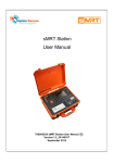
Report ITU-R M.2285-0 (12/2013) Maritime survivor locating systems and devices (man overboard systems) – An overview of systems and their mode of operation M Series Mobile, radiodetermination, amateur and related satellite services ii Rep. ITU-R M.2285-0 Foreword The role of the Radiocommunication Sector is to ensure the rational, equitable, efficient and economical use of the radio-frequency spectrum by all radiocommunication services, including satellite services, and carry out studies without limit of frequency range on the basis of which Recommendations are adopted. The regulatory and policy functions of the Radiocommunication Sector are performed by World and Regional Radiocommunication Conferences and Radiocommunication Assemblies supported by Study Groups. Policy on Intellectual Property Right (IPR) ITU-R policy on IPR is described in the Common Patent Policy for ITU-T/ITU-R/ISO/IEC referenced in Annex 1 of Resolution ITU-R 1. Forms to be used for the submission of patent statements and licensing declarations by patent holders are available from http://www.itu.int/ITU-R/go/patents/en where the Guidelines for Implementation of the Common Patent Policy for ITU-T/ITU-R/ISO/IEC and the ITU-R patent information database can also be found. Series of ITU-R Reports (Also available online at http://www.itu.int/publ/R-REP/en) Series BO BR BS BT F M P RA RS S SA SF SM Title Satellite delivery Recording for production, archival and play-out; film for television Broadcasting service (sound) Broadcasting service (television) Fixed service Mobile, radiodetermination, amateur and related satellite services Radiowave propagation Radio astronomy Remote sensing systems Fixed-satellite service Space applications and meteorology Frequency sharing and coordination between fixed-satellite and fixed service systems Spectrum management Note: This ITU-R Report was approved in English by the Study Group under the procedure detailed in Resolution ITU-R 1. Electronic Publication Geneva, 2014 ITU 2014 All rights reserved. No part of this publication may be reproduced, by any means whatsoever, without written permission of ITU. Rep. ITU-R M.2285-0 1 REPORT ITU-R M.2285-0 Maritime survivor locating systems and devices (man overboard systems) – An overview of systems and their mode of operation (2013) 1 Scope This Report addresses the design and use of devices and systems being developed, tested and deployed for use in detecting and resolving “man overboard”1 incidents. These incidents involve persons unintentionally being in the water, becoming susceptible to drowning or otherwise becoming incapacitated. The technologies discussed provide alerting/locating functions and as such are applicable to any situation in which a person needs assistance to be recovered from the water. Given the variety of applications for “man overboard” (MOB) systems, probably no single solution is suitable for all cases. The information provided in this Report is intended to assist in the understanding of devices and systems, leading to the development of performance criteria, and a possible new ITU-R Recommendation. Systems can involve personnel and their parent vessel/designated station(s) or they can seek to involve maritime rescue centres and/or all stations in the vicinity of the man overboard. Two categories of devices and/or systems are identified, based on whether the devices send alerts (i.e. notifications or emergency signals)/ to a designated station(s) or to all stations. This Report does not discuss the use of Cospas-Sarsat 406 MHz personal locator beacons (PLB) in a MOB scenario as these devices are adequately described elsewhere, but examines other technologies which can be used. It should be recognized that regional variations for the authorized usage of the devices and systems described in this Report exist, and need to be considered by the manufacturer and user regarding device or system selection and application. In some regions, some devices and systems may not be permitted. This Report describes generic criteria applicable to MOB devices falling into the two categories described above. It provides technical and operational information on the various options available, along with design objectives and limitations. In particular, this Report provides information on how the various systems and devices relate to the systems and procedures of the global maritime distress and safety system (GMDSS), where applicable. This Report recognizes that some MOB systems can use non-radio techniques for different phases of operation. Such systems may use radio receivers or other means to determine subsequent modes of operation. In addition, certain MOB systems may use non-radio techniques (e.g. acoustic signals) to communicate the MOB event to a vessel. The non-radio elements of such MOB systems are outside the scope of this Report, but such systems may use radio elements that are described in the Report. 1 The term “man overboard” is in common use in Recommendation ITU-R M.493 and in user interfaces for radio equipment used aboard ship. The term “person overboard” is used in the IMO’s Standard Marine Communications Phrases (IMO Resolution A. 918(22)) and the Joint IMO/ICAO International Aeronautical and Maritime Search and Rescue Manual. In this Report, the term “MOB” and “man overboard” has the meaning “person overboard” since the term “POB” is in widespread use with the alternative meaning of “persons on board”. The three-letter signal MOB in the International Code of Signals means “Patient is suffering from heat stroke”. The single-letter signal “O” (‘oscar’) in the International Code of Signals means “Man overboard”. 2 2 Rep. ITU-R M.2285-0 Introduction MOBs can provide an extremely effective aid to recovering personnel who have fallen overboard, or otherwise find themselves in the water unintentionally, becoming susceptible to drowning or otherwise becoming incapacitated. Man overboard devices continue to be developed and can utilize a range of techniques for their operation. This Report seeks to provide guidelines for their development so that: – a consistent level of performance is achievable irrespective of the techniques utilized; – the application and capability of the device is evident to a purchaser of the equipment; and – the performance of the equipment “fits into” existing distress and urgency alerting and communication arrangements and does not cause interference or harm. The general operational requirements for “Man overboard” devices are to: – provide immediate notification to the parent vessel relating to the man overboard incident; – provide a means of location to determine the position of the man overboard. These should provide rapid and sufficient information to a responsible person on board a parent vessel to enable a decision to be quickly reached as to whether external assistance is required or whether on-board assistance is adequate to deal with the situation. In some cases, the responsible person on board may decide to transmit an urgent message (i.e. with urgency priority). The decision then to escalate this to a Distress priority level rests with the responsible person on board. Some administrations advise or are of the view that a distress situation should be declared immediately following a MOB incident. In situations where for example there is no one on board, or no person on board who is capable of assisting, the devices are to: – provide a means of alerting maritime rescue centres and/or vessels in the vicinity of the man overboard to the situation; – provide a means of indicating the position of the man overboard while ensuring that the integrity of the GMDSS is not jeopardized; – provide a means of updating the position of the man overboard again without jeopardizing the operation of the GMDSS. It must be remembered that there can be several almost simultaneous MOB events from a single vessel. MOB systems are available on the market that operate on a range of frequencies including internationally designated frequencies (e.g. GMDSS distress and safety frequencies, automatic identification system (AIS) channels, the 121.5 MHz homing and aeronautical distress frequency, or other frequencies). The overriding concern is to ensure that the use of distress and safety frequencies by man overboard devices should not compromise the integrity of GMDSS and aeronautical distress and safety systems. 2.1 Usage of certain terms In this Report, it is acknowledged that various terms are used by industry and regulations to describe the radio signal being transmitted by a man overboard device and/or system. Examples include “alert”, “notification”, “distress alert” and “distress call”. These might be interpreted as being somewhat inconsistent with definitions in the Radio Regulations, or the GMDSS. Rep. ITU-R M.2285-0 3 The reason is that where such transmissions do not enter the GMDSS, and thus the international search and rescue system, they cannot be guaranteed of a response, and thus are not considered “distress alerting devices”. Radio Regulations No. 32.1 (WRC-12) defines the distress alert as: a) the distress alert is a digital selective call (DSC) using a distress call format, in the bands used for terrestrial radiocommunication, or a distress message format, in which case it is relayed through space stations; b) the distress call is the initial voice or text procedure; c) the distress message is the subsequent voice or text procedure; d) e) the distress alert relay is a DSC transmission on behalf of another station; The distress call relay is the initial voice or text procedure for a station not itself in distress. The international convention for the safety of life at sea (SOLAS) Chapter IV, Regulation 2.8 states “Locating means the finding of ships, aircraft, units or persons in distress”. In this Report, however, the term ‘alert’ is used more generally, in order to reflect usage with existing devices, and is similar to an important notification or emergency signal. The term “distress alert” is intended to refer to alerts or notification signals sent from man overboard devices with Distress priority and which are capable of being received by GMDSS stations in accordance with RR No. 32.1. When comparing the different man overboard devices and systems described in this Report, certain parameters or stipulations may appear inconsistent, which is the result of devices developed under national arrangements, and input contributions from Administrations to this Report. A possible future Recommendation may codify these inconsistencies for better classification. 2.2 International Maritime Organization guidance on man overboard devices using automatic identification system technology The International Maritime Organization (IMO) in 2012, considered man overboard devices which use AIS technology, in both the sub-committee on radiocommmunications and search and rescue (COMSAR) and the sub-committee on safety of navigation (NAV). Relevant conclusions can be summarised as follows: These locating devices (e.g. man overboard devices) which use AIS technology2: 1) should not be used for distress alerting; and 2) should not be used for routine location (being not in an emergency situation). The IMO has also indicated that these AIS devices must be regarded as location aids in emergency situations and not as distress alerting systems. Little specific international guidance on MOB-AS notifications is currently available, however continued work in this area can be expected. In June 2013, the IMO published a Safety of Navigation Circular (SN.1/Circ.322), Information on the display of AIS-SART, AIS Man Overboard and EPIRB-AIS devices. 2 COMSAR 17/7/1 (paragraph 3), (17 August 2012), IMO. 4 3 Rep. ITU-R M.2285-0 Generic criteria for Man Overboard Systems As described, MOB systems can be used for alerting to a selected station(s) or to all stations. To establish the difference, man overboard-all stations (MOB-AS) systems refer to all stations alerts and man overboard-designated station(s) (MOB-DS) systems to alerts sent to a designated station(s). Some systems may act as both MOB-DS and MOB-AS in sequence or in combination, and in each case, both sets of criteria need to be followed and the nature of the transition from one to the other clearly set out. In all cases, the devices should achieve their performance when numerous devices are operating in close proximity of each other. It has been suggested that the devices should achieve their performance when at least 10 similar devices are operating in a circular area of diameter 100 metres. 3.1 Man overboard-designated station(s) 3.1.1 Definition A device capable of being worn and manually activated by an individual or automatically activated by a man overboard event that causes an alert at a designated station(s). It is part of a personal notification system comprising a base station and one or more MOB-DS. 3.1.2 Specification The system should provide a means to register each individual MOB-DS on the system and when not in use, de-register or remove them from the system. When a registered MOB-DS causes an alert at the base station the station should generate an audible alarm at the station which should be manually acknowledged by a responsible person. It has been suggested that the system should have a probability of alert at the base station of 60% within 20 seconds or 95% within 30 seconds of the MOB event occurring. The base station should be capable of identifying the alerting MOB-DS and displaying its location either on a discrete display or integrating the information into a general purpose situational awareness tool such as an electronic chart display and/or radar. When two or more casualties occur at the same time, up to the maximum number of registered MOB-DS, the system should be capable of monitoring each one discretely without significant degradation in service. It has been suggested that on each alert event, the base station should capture the present location, either by built-in equipment to a range accuracy of ±40 metres or external equipment to the same accuracy, by at least one of the following: – storing the position; – provide a trigger to other equipment to store the position. Where the base station stores the position(s) it should be possible to display each position on demand on the base station. It has been suggested that the system should be capable of regularly updating the position of the casualty to a minimum range accuracy of ±40 metres or direction to within ±15 degrees. The maximum update interval should be 5 minutes. The system should provide a simple test arrangement to demonstrate the correct operation of each registered MOB-DS. Rep. ITU-R M.2285-0 5 The power supply of each MOB-DS should be sufficient for 12 hours continuous operation, the base station should be provided with two independent sources of power. A means to prevent inadvertent operation is to be fitted. If the base station is provided with a means of machinery control in the event of an alert, such arrangements are to be clearly stated at the base station with a means to override this. The alerting should operate without degradation within 100 m of another base station. A MOB-DS should not interfere with the operation or use of a life jacket if it is to be used in conjunction. Compliance with environmental and equipment safety standards for MOB-DS and base stations should be required. 3.2 Man overboard-all stations 3.2.1 Definition A device capable of being worn and manually activated by an individual or automatically activated resulting from a man overboard event that causes an alert or notification be sent to all stations. 3.2.2 Specification The alert should be either on a GMDSS alerting frequency (i.e. distress alert) or frequencies assigned to AIS 1 and/or AIS 2 (i.e. locating/notification signal). A means to prevent inadvertent initiation should be provided. A device using AIS technology in its current form cannot, of itself, be used to alert all stations on a person in distress, but studies have shown that it has significant value for locating the man overboard. Devices combining both DSC and AIS technology can perform both functions. Devices should conform to international standards, rules and guidance for the shared use protocols, signalling arrangements and operation of GMDSS frequencies, and should minimize interference with another simultaneous emergency use. Where remote acknowledgements are required the device shall contain receiving equipment. Repeat synthetic voice transmissions on a radiotelephony channel are not permitted. Information transmitted via GMDSS frequencies or AIS 1 and/or AIS 2 should include position of device, identification, and where possible, set and drift. Distress Alerts on VHF Channel 70 should continue until a remote acknowledgement is received. One administration has suggested that in sea state 63 the equipment should have a 95% probability of detecting an acknowledgement within 5 minutes of acknowledgement initiation by a station at a range of 5 nautical miles (approx. 9.3 km). Following a specific request, the device should be capable of transmitting an updated position to the requesting station. Where GMDSS procedures anticipate radiotelephony and this is not available, the alert should indicate this to the receiving station. Continuous position information to be provided to the transmitter. One administration has suggested that for VHF operation, the minimum range of transmission should be 2 nautical miles (approximately 3.7 kilometres) with an antenna height of 0.5 metres to a receive antenna at 30 metres above the sea surface. Consideration should be given to the optimum transmission range given that an excessive range may be counterproductive in some circumstances. A provision should be made so that the transmitter can be remotely restarted, where applicable. 3 The World Meteorological Organization definition of “sea state 6” corresponds to a wind (sea) wave height from 4 to 6 m, with a characteristic called “very rough” (Douglas Scale). 6 Rep. ITU-R M.2285-0 Display lights should be fitted indicating transmission status. Battery capacity must be adequate. A built-in test capability should be provided. A MOB-AS should not interfere with the operation or use of a life jacket if it is to be used in conjunction. Compliance with environmental and equipment safety standards for MOB-AS and base stations should be required. 3.2.3 Combination of functions MOB devices may combine the characteristics of MOB-DS and MOB-AS as described in an example Annex to this Report. In such cases, the device should be clearly marked as such and should conform to the minimum criteria described above for both types of device. Because of the long-standing incessant alarming over DSC-equipped VHF radios caused a nuisance to mariners in some regions of the world, some operators have ignored DSC alarms or turned off their radios. Consequently some MOB devices using channel 70 DSC technology initially operate in a designated station mode when activated, until some predetermined period of time has elapsed. One Administration requires this delay to be not less than five minutes. It was anticipated that during this delay, alerts would have time to be cancelled if false and persons falling overboard could be best rescued by the ship operating the designated station (parent vessel). Nevertheless the relatively short detection ranges of these devices (see § 5) and inclusion of an electronic positionfixing receiver integral to the device precludes the likelihood that these devices would contribute to the DSC alarming problem. Therefore some Administrations are of the view that there may presently be no need for DSC-equipped MOB devices to delay going into an all-stations alerting mode when activated. 3.3 Use scenarios 3.3.1 Man overboard-designated station(s) – Scenario 1 Parent vessel has a “system controller” or other device monitoring all MOB-DS worn by persons on board. The MOB-DS transmit either continuously or frequently and are monitored by the system controller which monitors all MOB-DS on board. When a person(s) falls overboard, the radiocommunication link is broken to the system controller, and a MOB alarm is activated. The remaining crew aboard the parent vessel would then take appropriate action to recover the person from the water, and the responsible person aboard the vessel may, if considered necessary, transmit additional messages to vessels in the vicinity or to stations ashore. 3.3.2 Man overboard-designated station(s) – Scenario 2 Parent vessel has a system controller or other device monitoring a single MOB-DS worn by the sole crew member. The MOB-DS transmits either continuously or frequently is monitored by the system controller. When the sole crew member falls overboard, the radiocommunication link is broken to the system controller, and the MOB alarm may be used to cause propulsion to be stopped on the vessel, and other actions such as switching on extra lighting. The MOB-DS device may then cause an alert to a designated station(s) ashore. It may then later also change to MOB-AS mode and send a message to all stations. The change to MOB-AS mode would be useful in the case of the parent vessel sinking or otherwise not being able to respond. Rep. ITU-R M.2285-0 3.3.3 7 Man overboard-all stations – Scenario 1 Parent vessel has a receiver monitoring a specific channel(s). Persons on board are wearing MOB-AS. When a person(s) fall(s) overboard, the MOB-AS transmitter is activated and an alert(s) is sent to all stations. Receivers monitoring the channel(s) activate an alarm aboard the parent vessel and all stations in range. The remaining crew aboard the parent vessel would then take appropriate action to recover the person from the water, and the responsible person aboard the vessel may, if considered necessary, transmit additional alerts and/or messages to vessels in the vicinity or to stations ashore. 3.3.4 Man overboard-all stations – Scenario 2 Parent vessel has a receiver monitoring a specific channel(s). Person(s) on board are wearing MOB-AS. When a person(s) fall overboard, the MOB-AS transmitter is activated and an alert(s) (e.g. DSC distress alert) is sent to all stations. The vessel then sinks, or cannot respond due to other circumstances. Receivers monitoring the channel(s) activate an alarm aboard other vessels and shore stations in range. Vessels in the vicinity may then respond, and stations ashore may initiate appropriate search and rescue response. 3.4 Sequence diagrams Annex 1 (Figs 1 to 5) contains sequence diagrams for MOB-DS and MOB-AS operational sequences. 4 Field evaluation of man overboard devices and systems Ideally, the various MOB systems available should be subject to live trials in order to: – determine the operational envelope, in particular the effective range in a number of scenarios, including survivor searches by: – a vessel with no special equipment; – specialised search and rescue (SAR) vessels; and – specialised SAR aircraft; – establish the impact of such devices upon SAR asset operational management and resourcing. 5 Detection ranges Table 1 shows typical detection ranges for various MOB devices. 8 Rep. ITU-R M.2285-0 TABLE 1 Typical detection ranges Typical surface detection range by ship/(antenna height) Typical detection range by aircraft/(altitude) 156.525 MHz (Annex 2) 1-5 NM (2-9 km)/(10 m)4 20-30 NM (37-56 km)/ (2 000 ft) 121.5 MHz (Annex 4) 8 NM (14.8 km) /(2 m)5 40-70 NM/(30 000 ft)6 System frequency 162 MHz (Annex 5) 6 1 NM (1.85 km) / (0.5 m)7 3 NM (5.6 km) / (6.5 m)8 4 NM (7.4 km) / (17 m)9 13 NM (24.1 km) / (shore station)10 Detectable by low earth orbiting satellite No No 7 20 NM (37.0 km) / (300 ft) 53 NM (98.2 km) / (1 000 ft)7 65 NM (120.4 km) / (5 000 ft)7 94 NM (174.1 km) / (10 000 ft)7 Yes Identification and display of man overboard devices It is recognized that MOB devices which interact with GMDSS and AIS equipment (receivers and transmitters) require unique numerical identities which are unambiguous and compatible with international practice. Recommendation ITU-R M.585 contains further guidance on appropriate unique numerical identities and provides further guidance. The Comité International Radio Maritime (CIRM) has been appointed and agrees to assign blocks of identities to manufacturers11. MOB devices operating as described in Annex 2 (Devices using VHF channel 70 (RR Appendix 18)) and those operating as described by Annex 5 (Devices using AIS) should use the freeform number identity prescribed for man overboard devices that transmits DSC and/or AIS as specified in Recommendation ITU-R M.58512. DSC-only designated station devices may use the group station call identity format for the period of designated-station operation, in order to allow vessels operating as a group to monitor MOB devices deployed by other vessels in the group. Transmissions from MOB devices operating as described by Annex 5 (AIS) may be displayed on ship’s navigation display. Such MOBs may be indicated on a newer graphical display of AIS by a circle with an "X" inside it, as shown in Fig. 1. MOBs can be distinguished from AIS-SARTs used 4 Estimated from published commercial information. 5 Ideal conditions with no path obstruction via purpose-built directional antenna and receiver. 6 From published commercial literature. 7 From United Kingdom trials using D Class inshore (near coastal) lifeboat (2012), RNLI. 8 From United Kingdom trials using Trent Class (offshore) lifeboat (2012), RNLI. 9 From IEC 61097-14 Annex A. 10 From United Kingdom trials using AIS Coastguard station (2012), RNLI. 11 http://www.cirm.org/sartno.htm. 12 972xxyyyy, where xx = manufacturer ID 01 to 99: yyyy = the sequence number 0000 to 9999. Rep. ITU-R M.2285-0 9 for other purposes, or in Fig. 2 from other ships, by the first three digits of its maritime identity being “972”. MOB devices which do not interact with GMDSS or AIS equipment may use proprietary numbering schemes if required for operation of the MOB system. FIGURE 1 Aeronautical identification system – man overboard navigation display symbol Symbol (AIS-SART or MOB) Alternatively, in Fig. 2 the MOB may be indicated on an older graphical display of AIS as a normal (sleeping) AIS target (isosceles triangle), as shown, taking into account that the triangle may be oriented by course over ground13. FIGURE 2 Aeronautical identification system – man overboard older navigational display symbol SYMBOL (AIS TARGET) FIGURE 3 Manually entered event mark, clarified by added text (e.g. “MOB” for man overboard cases) Symbol (Event Mark) MOB 13 Extract from IMO SN.1/Circ. 322 and SN.1/Circ. 243, -243 Add.1 and -243 as amended by NAV 59. 10 Rep. ITU-R M.2285-0 IEC in cooperation with U.S. National Marine Electronics Association is developing a data interface definition to provide notification from stations receiving man-overboard device transmissions regardless of technology used for inclusion in its IEC 61162 series standards. AIS-SART MOB data is sent with other data from the AIS equipment via the AIS data sentence, which is recognized by IMO-mandated navigation displays. DSC MOB data is sent from a DSC-equipped VHF marine radio via the DSC data sentence, and data from MOB designated station base stations can be sent via the MOB sentence. Data available in this MOB data sentence includes MOB position, MOB status, coordinated universal time of MOB activation, position source, coordinated universal time of position, course over ground, MOB maritime identity, and MOB battery status. IMO-mandated navigation displays are not required to recognize DSC or MOB data sentences, although in the future some may do so on a voluntary basis. 7 External labelling of man overboard devices It is important that any MOB device be physically labelled so that its purpose is readily understood, and that it cannot be confused with devices which have a different purpose. It is recommended that the user manual clearly states “THIS IS NOT AN EPIRB OR PLB” or words to that effect. The colour of the MOB device exterior surface should be a colour which is highly visible. Any floatation aid attached to the MOB device should also be of a colour which is highly visible. The IMO Maritime Safety Committee has invited Member States to advise manufacturers to affix product labels to the equipment AIS-SART and AIS-MOB, clearly indicating that these AIS devices must be regarded as location aids in emergency situations and not as distress alert systems”14.The CIRM observer advised that ITU-R Working Party 5B had invited CIRM to issue the manufacturer identification (id) number to such AIS-based devices. Accordingly, CIRM would add this labelling information to the documentation circulated when manufacturers requested an id, and would also inform all existing holders of id numbers of this requirement. 8 Operational considerations Due to the variety of maritime activities and maritime environments encountered, a single type of MOB device or system is unlikely to be suitable for all situations. Some factors to be considered are listed in Table 2: 14 MSC 91/22, paragraph 12.9, Report of the Maritime Safety Committee on its Ninety-First Session, 17 December 2012, (IMO). Rep. ITU-R M.2285-0 11 TABLE 2 Some operational considerations when choosing a man overboard/maritime survivor locating device or system Equipment-related Durability (weather and climatic conditions) Detection range (vessel(s), coast station(s), aircraft, satellites) Bridge watch-keeper alerted (own ship and/or others) Selective and/or all ships signalling Battery life User replaceable battery Integral lamp or strobe light User-related Risk level of personnel to a MOB incident Single-handed vessel Professional or recreational use Ease of use Situational Proximity of AIS stations (for AIS-MOB devices) Potential number of simultaneous MOB events Which GMDSS sea area Who/what is monitoring Administrative Regulatory provisions in the expected operational area Need for registration or user identification 8.1 Offshore working environments It should be noted that similar considerations to the previous section could apply to offshore working environments such as petroleum oil and gas installations, offshore wind farms, wave energy power installations, aquaculture installations and similar environments. 9 Principles of man overboard systems currently available Man overboard systems are dealt with in greater detail in Annexes 2 to 6. Some systems/devices are capable of functioning either as a MOB-DS or MOB-AS or both, and the generic criteria need to be considered in relation to these. The advantages or disadvantages then become clearer. The use of 121.5 MHz as an alerting frequency as described in Annex 4 requires some further discussion and the following comments are relevant. 9.1 Man overboard – all stations principles There are two commonly available technologies which can be used to immediately notify all shipping in close vicinity of a survivor in the water needing rescue: DSC on VHF channel 70, and AIS on VHF channels AIS 1 and 2. AIS has the advantage of instantly identifying with appropriate symbology on the navigation display of nearby shipping the location of a survivor or survivors in the water, but AIS may not be used to alert shipping that there is a person in distress. AIS devices have the further advantage of relatively low cost, since unlike DSC it does not require use of a VHF receiver. DSC can provide an immediate alert to shipping that there is a person in distress, but cannot readily display that information on a ship’s navigation display. Some ship operators discount 12 Rep. ITU-R M.2285-0 receipt of a DSC distress alarm due to experience with false alerts, urgent marine information broadcasts and other causes of incessant alarming. Therefore there is advantage in using AIS technology, and where sounding an alerting alarm is essential, in combining both DSC and AIS technologies in MOB-AS devices. 9.2 Aeronautical distress and safety systems and 121.5 MHz The International Civil Aviation Organization (ICAO) views MOB as localized alerting devices, i.e. MOB are not designed primarily to alert the International SAR system but rather to alert the parent vessel/platform of an emergency man-overboard situation and instigate self-help to alleviate the problem. Urgent recovery action should be undertaken by the parent vessel/platform. The use of 121.5 MHz would be of assistance if the situation expanded beyond the capabilities of the parent vessel and required the assistance of SAR assets. To this end, ICAO SAR would not object to 121.5 MHz being used for the purpose of MOB beacons. However, ICAO is of the view that there may be more appropriate frequencies to use, which could not only assist SAR assets in homing situations, but also allow for support from nearby vessels, e.g. marine channel 16. Furthermore, ICAO is of the view that under no circumstances should the use of distress and safety frequencies by MOB devices interfere with the aeronautical distress and safety system. 9.3 Usage of 121.5 MHz for man overboard devices In the view of ICAO there are the following advantages and disadvantages of using 121.5 MHz for a MOB device: Advantages: – A 121.5 MHz signal could be used by direction finder equipped SAR aircraft/vessels to locate MOB device should the parent platform/vessel be unsuccessful in locating and recovering the person. (One would assume that the parent platform/vessel has been unable to locate or assist the MOB device for whatever reason, and the SAR system has been activated to assist.) Disadvantages: – No satellite detection of the 121.5 MHz signal to assist with position information and drift. – Inadvertent activations, in coastal regions particularly, is likely to add to the already high rate of false alerts detected by overflying aircraft on the emergency channel. This will add to the cost of providing SAR, as determination of a genuine emergency, or not, cannot be concluded unlike with current 406 beacons, until after the beacon is found and turned off. – If multiple MOB beacons are activated from a single vessel/platform then the ability to direction finding to the beacons by SAR assets is seriously compromised due to the known limitations with direction finding equipment where multiple signals are radiating in a small area15. – 121.5 MHz is not a frequency routinely carried by maritime vessels, this limits support assistance that may be provided by nearby vessels to the MOB event. Finally, if such devices are to be produced, then ICAO would request that they are built with a similar level of requirement for integrity and reliability as current emergency locator transmitters (ELTs) in order to minimize the number of false alerts. 15 However, modern direction finding receivers using phase-discrimination techniques to determine a bearing to target will lock on to the strongest target signal due to the FM capture effect. Such receivers are not considered to be seriously affected by multiple 121.5 MHz MOB transmitters being active simultaneously. Rep. ITU-R M.2285-0 13 Applying this reasoning, the use of 121.5 MHz for MOB devices would appear to have limited applications. 9.4 Modern 121.5 MHz direction-finding technology A manufacturer of direction-finding (DF) equipment has provided additional information on 121.5 MHz DF equipment which is widely used by a number of manufacturers, which use the pseudo-doppler DF technique. The pseudo-doppler DF uses a standard FM receiver to derive a benefit from the FM capture effect. The phase angle of the wave front encounters a circular array of antennae (e.g. three or four antennas) and the RF signals from each antenna into the FM receiver are split (i.e. chopped) using RF switches. The chopped signal is integrated to form phase modulation from the demodulated output to obtain the original phase difference information between each antenna. A trigonometric operation is performed, followed by averaging, to calculate the bearing to the 121.5 MHz transmitter. This technique causes errors in bearings as a result of residual FM in the beacon’s modulator and Recommendation ITU-R M.690-2 (paragraph 2 (d)) includes the spectral carrier power ratio requirement which was an existing requirement in the ETSI EN 300 152 (now EN 302 961) standard. The Oil & Gas UK Emergency Locator Beacon Guidance 201116 contains the following statement in paragraph 3.0 in relation to DF homing on 121.5 MHz beacons: “Crews should also ensure they are aware of how their equipment ‘behaves’ when it encounters multiple signals. Most modern direction finding equipment will home in on the strongest signal but this should be verified by the crew for each individual piece of equipment.” This statement lends support to the view that DF homing on 121.5 MHz beacons will point to the strongest signal and not be confused in a multiple 121.5 MHz beacon activation situation. 10 Overall conclusions As can be seen from the Annexes there are a number of ways of satisfying the generic requirements. With future technological developments these annexes cannot be considered exhaustive. The need for effective MOB devices is clear both from the demand for devices that are currently available and particularly from the needs of the leisure industry where MOB casualties are among the highest. Currently the only technology which will enable the location of an activated MOB to be displayed on an IMO-mandated shipboard navigation display is AIS. However, an AIS-MOB mark on a ship navigation display may go unrecognized if it is not being looked for. Therefore, for devices capable of alerting all ships in the vicinity of the location of a survivor in the water needing immediate assistance, where use of devices alerting designated stations only is inadequate, there is advantage in MOB-AIS devices using combined AIS and DSC technology. 16 http://www.oilandgasuk.co.uk/cmsfiles/modules/publications/pdfs/HS063.pdf. 14 Rep. ITU-R M.2285-0 The wide variety in the performance of currently available products and the potential for misunderstanding of their limitations by the general public would imply the need for some universality in the capabilities of these and an easy to understand terminology that would allow the public to select the right device for a particular application. The need for effective generic criteria is thus established. Annexes: 8 Rep. ITU-R M.2285-0 Annex 1 A1 Sequence diagrams for personal distress devices and their operation FIGURE A1.1 Man overboard-designated station(s) sequence diagram – man overboard-designated station(s) device ACTION Action taken by device STATE State where device waits for an event EVENT Event triggered by person, outside circumstances or parts of the device LEGEND 15 16 Rep. ITU-R M.2285-0 FIGURE A1.2 Man overboard-designated station(s) sequence diagram – man overboard-designated station(s) base unit Turn on base system Start of MOB action MOB Base - armed MOB Base – Rx Designated MOB alert from MOB device MOB Base – Signal MOB situation to Crew MOB Base - Tx Ack to MOB Device MOB Base – MOB action ongoing MOB Base – Rx Designated MOB alert from MOB device MOB Base - Manual deactivation of ongoing MOB action Update position of MOB device on display MOB Base – Stop MOB Action ACTION Action taken by device STATE State where device waits for an event EVENT Event triggered by person, outside circumstances or parts of the device LEGEND Rep. ITU-R M.2285-0 FIGURE A1.3 Man overboard-all stations sequence diagram – digital selective calling device ACTION Action taken by device STATE State where device waits for an event EVENT Event triggered by person, outside circumstances or parts of the device LEGEND 17 18 Rep. ITU-R M.2285-0 FIGURE A1.4 Man overboard-all stations sequence diagram – automatic identification system device Turn on device Start of MOB action MOB device - armed MOB Event MOB Device – Tx AIS-MOB Message MOB device - armed and active MOB Device - Wait Timer Send again Manual Deactivation MOB Device – Tx AIS-MOB Message Turn off device End of MOB action ACTION Action taken by device STATE State where device waits for an event EVENT Event triggered by person, outside circumstances or parts of the device LEGEND Rep. ITU-R M.2285-0 FIGURE A1.5 Man overboard-all stations sequence diagram – Norwegian device ACTION Action taken by device STATE State where device waits for an event EVENT Event triggered by person, outside circumstances or parts of the device LEGEND 19 20 Rep. ITU-R M.2285-0 Annex 2 A2 Devices using VHF Channel 70 (Radio Regulation Appendix 18) A2.1 Global navigation satellite service receiver “Man Overboard” devices using all station alerts on VHF DSC channel 70 should include a GNSS receiver in order to ensure that a position of the person overboard is immediately available, thus facilitating recovery and minimizing the duration of repeated alerts. A2.2 VHF channel 70 receiver These devices may be fitted with a VHF channel 70 receiver, to allow DSC acknowledgment messages to be sent by ships and coast stations. A DSC acknowledgment message will stop the device from sending further distress alerts, in accordance with COMSAR/Circ. 25. Devices with a receiver may implement a listen before talk protocol, using the prioritised wait scheme described in Annex 4 section 3.1.8 of Recommendation ITU-R M.493-13. A2.3 Visual indicator A visual indicator on the maritime survivor locating system (MSLS) that activates upon an acknowledgment message being received would also serve to alert the person in the water that assistance is on the way. A2.4 Functional overview A suggested operational scenario is summarized in the table below: TABLE A2-1 Digital selective calling man overboard operational scenario Time/event Action Comments Initial switch on DSC designated station(s) alert sent (Note 1) Minimizes false alerts by restricting the message to the parent vessel or group. GPS lock DSC all stations alert sent DSC ox on (Note 2) DSC ask message received DSC TX off DSC ox off Indicator on beacon turns on If no DSC acknowledgment message received, beacon continues with the “default” cycle of a DSC message every 5 min for 30 min, and then every 10 min. These messages will be stopped if an acknowledgment message is received. NOTE 1 – Some Administrations require the device to remain in “designated station” mode for a specific period of time. NOTE 2 – Some devices may also leave the DSC receiver on when an acknowledgment message is received, to allow the device to respond to further requests for position. A2.5 Identification It should also be noted that use of DSC and AIS technology will require use of numerical identities. Rep. ITU-R M.2285-0 A2.6 21 Advantages and disadvantages The relative advantages and disadvantages of the use of distress and safety frequencies and systems in handling man overboard incidents are considered below: Advantages in the case of a designated station(s) system: – The vessel best positioned to respond to the incident is immediately alerted – although this is also an advantage with open loop systems. – The use of a Group Call would permit notification of the incident to a dedicated Group. Advantages in the case of an all station system: – Ships and shore SAR services in the area will already be monitoring the distress frequency. – Immediate indication to SAR services of a potential distress incident, thus ensuring rapid response. Disadvantages in the case of a designated station system: – A potential delay in notifying SAR services. – Method of alerting may not likely comply with certain provisions of the current Recommendation ITU-R M.493 or the Radio Regulations. – Stringent need to programme the correct numerical identity into DSC controllers. – If the parent vessel’s DSC radio is malfunctioning, or being de-sensed through use on another channel, the alert may not be received. – If the parent vessel sinks, the MSLS device (MSLD) alert may not be received. – If the MSLD is inadvertently taken onto another vessel (e.g. fishing personnel changing vessels at the last minute, for example), the beacon may not work. – Some earlier model DSC transceivers do not correctly receive a distress relay alert, the format used in closed loop DSC man overboard systems. A2.7 Regional variations Some administrations allow variations of the all stations system. These regional variations should be considered when evaluating the suitability of MSLS systems and devices for use in a particular area. A2.7.1 Example 1 (based on Australian/New Zealand standard AS/NZS 4869.2 Type A maritime survivor locating system) A low-powered transmitter is worn by persons at risk of falling overboard. A receiver on the parent vessel monitors the system radio frequency. Should a ‘man overboard’ incident occur, the transmitter is activated and the received signal initiates an alarm, and may in some cases, also be used for homing purposes to guide rescuers or the parent vessel, back to the person in the water. The following terms are used: Maritime survivor locating system transmitter. This is the portable transmitter carried by persons at risk of falling overboard. Its main purpose is to send a local alert to the parent vessel or facility, and possibly to other units nearby. The transmitter can also be used as a locating device to aid recovery. Maritime survivor locating system receiver. This is the unit which receives the alerting signal. The significance of the received signal is: i) For a Type A, it means an MSLS transmitter has been activated (in the terminology used in the Scope of this Report, this corresponds to the stand-by mode.) 22 Rep. ITU-R M.2285-0 Maritime survivor locating system locator. This is any device designed to locate the MSLS transmitter. It may be part of the MSLS, be a separate device, or be separate to particular MSLS system. Operational requirements – batteries The battery shall be contained with the MSLS transmitter, and allow replacement by the user readily in such a way to prevent incorrect installation. Watertight integrity is to be provided when the battery has been replaced. For Type A MSLS transmitters, additionally, the battery shall: i) be capable of operating the MSLS transmitter continuously for at least 6 hours (–10° C to + 55° C); ii) have a minimum shelf-life of two years; iii) not be rechargeable. Battery replacement Non-rechargeable batteries are to be replaced at half the declared shelf life. The replacement date for the battery is to be marked on the outside of the MSLS transmitter, be durable and easily read. TABLE A2-2 Basic maritime survivor locating system transmitter characteristics – using VHF channel 70 (156.525 MHz) – based on Australian/New Zealand Standard AS/NZS 4869.2 Type A maritime survivor locating system Nominal carrier frequency 156.525 MHz Carrier frequency error limit Frequency error shall not exceed ±5 parts per million Peak field strength (at 10 m) > 99 dBμV/m (in vertical plane) at nominal frequency Spurious emissions (at 10 m) < 75 dBμV/m (in vertical plane) for each spurious emission Necessary bandwidth < 16 kHz Class of emission G2B or F2B Modulation characteristics Frequency modulation with a pre-emphasis of 6 dB/octave (phase modulation) with frequency-shift of the modulating sub-carrier between 1 300 and 2 100 Hz, the sub-carrier being at 1 700 Hz. Modulation frequency tolerance < ±10 Hz (for 1 300 and 2 100 Hz tones) Modulation rate 1 200 baud Modulation index 2.0 ±10% DSC message format In accordance with Recommendation ITU-R M.493-12, Table 4.1, with nature of distress: ‘Man overboard’ (symbol 110), and type of subsequent communication; ‘No Information’ (symbol 126). Transmitter duty cycle For MSLS transmitters using DSC on VHF channel 70, the transmitter duty cycles shall be randomly selected times of between 4.9 and 5.1 and 9.9 and 10.1 min respectively. If a valid position has not been obtained, the position field in the DSC messages shall be replaced with the digit 9 and the time field replaced with the digit 8, coded in accordance with Recommendation ITU-R M.493-12. When activated MSLS transmitters shall transmit an initial distress message indicating Man Overboard. Rep. ITU-R M.2285-0 23 TABLE A2-2 (end) A GPS position shall be transmitted as soon as the integrated GPS receiver has a valid position. If multiple frequencies are available for transmission, the MSLS transmitter shall transmit the position information. After the first transmission containing a GPS position has been sent, the MSLS shall operate with a duty cycle of at least one report every 5 min for a period of 30 min, i.e. at least one transmission every 5 minute for a 30 min period (a maximum of 6 transmissions). After 30 min after activation, the duty cycle shall change to 10 min, until batteries are exhausted or the MSLS transmitter switched off. Compass safe distance test IEC 60945 (when transmitter not activated) Immunity to conducted RF interference IEC 60945 TABLE A2-3 Basic maritime survivor locating system receiver characteristics Reference Sensitivity Nil response to unmodulated carrier Compass safe distance test Immunity to conducted RF interference ≤ −105 dBm (AS/NZS 4768.2 test method) or compliant with IEC 61097-7 or IEC 62238 –47 dBm (for 1 min) IEC 60945 IEC 60945 TABLE A2-4 Additional receiver characteristics for Type A maritime survivor locating system GPS receiver GPS position output Time To First Fix (TTFF) GPS position indication (successful) GPS position indication (unsuccessful) Shall be fitted (compliant with IEC 61108-1). Automatically inserted into the MSLS transmissions. Less than 10 min in all modes of the beacon. Visual indication shall be provided to indicate when the GPS receiver is providing a valid position. If GPS position updates cannot be maintained after first position fix, then the last valid position and time of position shall continue to be transmitted. When a subsequent valid position is obtained, it shall be transmitted at the next transmission cycle. 24 Rep. ITU-R M.2285-0 TABLE A2-5 Basic maritime survivor locating system locator characteristics Sensitivity (i.e. correct operation at minimum wanted signal) Directivity (minimum resolution and accuracy) Compass safe distance test Immunity to conducted RF interference Minimum wanted signal = 10 dBμV/m ±5 degrees IEC 60945 IEC 60945 A2.7.2 Example 2 based on USA radio technical commission for maritime services standard 11901.1 Annex A digital selective calling type TABLE A2-6 Radio technical commission for maritime services standard 11901.1 Annex A device characteristics Designated station mode Yes – formatted as distress relay on behalf of another ship per Recommendation ITU-R M.493-13 All station mode Yes – after 5 min operation Duty cycle Every 5 min for 30 min period; every 10 min thereafter DSC receiver required Yes Distress alert terminated by distress acknowledgment Yes Internal position fixing device required Yes – per IEC 61108-1 Minimum operating time 12 hours Identifier 972xxyyyy Radiated power 100-500 mW Allowed in combination with AIS Yes Satellite detection possible No Annex 3 A3 Devices using other Radio Regulation Appendix 18 channels A3.1 Example 1 (Norway) Norway has developed an alarm system which is already operational on board fishing boats along the Norwegian coast. This system can make an important contribution in order to save lives of personnel aboard fishing vessels if a Man Overboard (MOB) accident should occur. A block diagram of the system is shown in Fig. A3-1. Rep. ITU-R M.2285-0 25 A3.1.1 Functional overview When the MOB device is activated, e.g. by a person falling overboard, a signal is transmitted via HF (27.145 MHz) to the MOB fixed unit on board the vessel. Then several actions are initiated, some on board the vessel, and others ashore, as the alarm is relayed by VHF data from the vessel to the nearest coast station. The coast station transmits a GMDSS DSC urgency announcement to all vessels in the vicinity via RR Appendix 18, Channel 70. The described system is mainly designated station, but the very last lap when the coast station transmits the GMDSS DSC urgency announcement may be considered an all station. Consequently, this system can be considered a combination system. The system operates in the stand-by mode, i.e. there is transmission only in the event of Man Overboard. The system may utilize various MOB devices. In the current set up the persons on board the vessel wear a compact portable transmitter operating on 27.145 MHz, and this unit transmits an alarm to a dedicated receiver on board the vessel. The installation of the alarm system is easily done by a competent technician. The system is designed for use in the extreme weather conditions in Norwegian waters. Both the portable transmitter and the on board units are developed to endure low temperature, rough handling, and humidity. The communication from the vessel to the coast station ashore is according to Recommendation ITU-R M.1842 (VHF data), and the coast station ashore relays the distress message through GMDSS VHF broadcast to all ships within Sea Area A1 within range. A3.1.2 Method of operation The backbone of the alarm system is the existing Norwegian VHF data system described in Recommendation ITU-R M.1842, Annex 2. This is a robust data communication system with a range of up to 120 km from shore, i.e. more or less sea area A1. The system operates in the maritime VHF frequency band and is covering all the 2 400 km coastline of Norway by approximately 80 base stations, some of these are situated on Norwegian offshore installations in the North Sea, expanding the coverage. Various MOB devices may be used with the alarm system. One of the devices consists of a compact portable transmitter, worn by the fisherman, with a fixed receiver on board the fishing vessel, connected to the VHF data system on board. The compact transmitter is breast pocket size, is transmitting on 27.145 MHz, and it has double encapsulation to prevent moisture ingress. The system is activated by pressing a button on the portable transmitter unit. The transmitter is very compact, and the user will have full freedom of movement on board the vessel. The transmitter is carefully designed to prevent inadvertent activation. The range of the portable transmitting device is about 550 m. The MOB device acts as a remote controlled emergency switch for the propulsion engine and other machinery on board the fishing vessel. Since the propulsion engine stops immediately, there is also a possibility for the fisherman to be able to get on board the fishing vessel single-handed. The MOB device may also activate a local siren and switch on all the lights on board the vessel. At the same time as the systems on board the vessel are activated, an emergency message is transmitted to the nearest coast radio station through the VHF data system. The message contains detailed information about the boat, such as maritime mobile service identity (MMSI) number and current position. At the Norwegian coast radio stations, the message is automatically visualized in a dedicated electronic map system called search and rescue application. 26 Rep. ITU-R M.2285-0 Using the GMDSS system, the professional radio operator at the coast radio station immediately forwards the DSC urgency announcement to ships in the vicinity of the accident, and at the same time informs the relevant search and rescue personnel. Fast and professional assistance is assured without any delaying intermediaries. FIGURE A3-1 Man overboard system designed for fishing vessels Annex 4 A4 Technical characteristics of devices using 121.5 MHz A4.1 Example 1 (based on AS/NZS 4869.1) This system is designed for very short-range crew retrieval, allowing self-help from the vessel or other external help, by sounding an alert from an on-board receiver, and a device on-board the vessel also giving directional information for the activated transmitter. The devices are part of Rep. ITU-R M.2285-0 27 an integrated system that may include some form of locating device such as direction finding equipment. They should be designed to also operate in conjunction EPIRB or other distress beacons covered by AS/NZS 4280 using 121.5 MHz as a homing frequency. The system comprises three parts, the MSLS transmitter, the MSLS locator and MSLS receiver incorporating a warning device. The MSLS transmitter is normally worn by a person at risk of falling overboard. It is made to withstand specified environmental conditions, such as specified in IEC 60945 for portable equipment, including compass safe distance (when not activated). The MSLS locator is the device to assist in the location of an MSLS transmitter (which is normally worn on a person). This device may be integral to the MSLS, or may be a separate device or may not be a part of a particular MSLS design. It is desirable that an MSLS locator be designed such that it may be used in conjunction with EPIRBs which use 121.5 MHz as a homing frequency. If there is connection between the ship’s power system and the MSLS locator, immunity to conducted radio frequency interference is as tested by IEC 60945. The MSLS receiver is the device to receive the alerting signal from one or more MSLS transmitters to indicate that a MSLS transmitter has been activated. A4.1.1 Operational requirements – transmitters Control of MSLS transmitters can be manually or water-activated, and have a test mode. The modes of the manually-activated only transmitters are OFF/ON/TEST. User-selectable modes for transmitters that are manually and automatically activated have modes of OFF/ON/READY/TEST. In the ready mode, the transmitter is normally deactivated, but will automatically activate when the transmitter is immersed in water, but there is to be an electronic delay to avoid inadvertent activation of the water switch. A4.1.2 Operational requirements – batteries Battery capacity sufficient to operate the MSLS transmitter continuously for at least two hours under all temperature conditions from –10°C to +55°C, has a minimum shelf life of two years, and is not rechargeable. A4.1.3 Basic 121.5 MHz maritime survivor locating system transmitter characteristics Nominal carrier frequency 121.5 MHz ±3 kHz Peak field strength (at 10 m) > 99 dBμV/m (in vertical plane) at nominal frequency Peak field strength (at 10 m) < 75 dBμV/m (in vertical plane) for each spurious emission Modulation Double sideband, full carrier, amplitude modulated to depth greater than 85% Modulation characteristics Audio frequency swept upwards or downwards though at least 700 Hz in the range 300 Hz to 1 600 Hz with a repetition rate between 2 Hz and 4 Hz. The delay between sweeps should not be greater than 1/10th of the sweep time. Modulation duty cycle 33% to 55% (transmitter operating with 100% duty cycle) Identification signal If national regulatory authorities permit, the sweep modulation cycles may be interrupted every 5 min for a period less than 60 s to permit transmission of an identification signal. During the identification signal, a clearly defined carrier should be retained. Compass safe distance test IEC 60945 (when transmitter not activated) 28 Rep. ITU-R M.2285-0 A4.1.4 Basic 121.5 MHz maritime survivor locating system receiver characteristics Reference sensitivity ≤ −105 dBm (AS/NZS 4768.2 test method) Nil response to unmodulated carrier –47 dBm (for 1 min) Compass safe distance test IEC 60945 A4.1.5 Basic 121.5 MHz maritime survivor locating system locator characteristics Sensitivity (i.e. correct operation at minimum wanted signal) Minimum wanted signal = 10 dBμV/m Directivity (minimum resolution and accuracy) ±5 degrees Compass safe distance test IEC 60945 Annex 5 A5 Technical characteristics of automatic identification system based systems NOTE – It is recognized that AIS-based systems are already being manufactured, and in the early stages of deployment in certain markets. Due to the similarity in operation to AIS-SARTs, the information shown in this Annex is considered useful for the understanding of this technology for AIS-MOB and possible EPIRB-AIS applications. A5.1 Technical considerations for proposed implementation of automatic identification system – man overboard and emergency position-indicating radiobeacon – automatic identification system The AIS-MOB and EPIRB-AIS applications are recommended to utilize the burst transmission method of Annex 9 of Recommendation ITU-R M.1371-4 as this format is specifically designed for use at low elevation in varying sea state conditions. No additional VDL channel loading assessments are required for the AIS-MOB and EPIRB-AIS as the assessments for AIS-SART sufficiently cover the burst transmission mode for the new system. The User ID (similar to an MMSI) structure currently used for AIS-SART will fully support the AIS-MOB and EPIRB-AIS functions. Additionally, given the anticipated low saturation of the AISMOB and EPIRB-AIS devices, specifications regarding the randomization of the slot are not required. An output power (EIRP) of one watt has demonstrated to be sufficient for the AIS-MOB and EPIRB-AIS devices. Within the Message 1 definition for the Navigation status parameter, the AIS-MOB and EPIRB-AIS devices should utilize states 14 and 15 in line with the actions of an AIS-SART device. Both the EPIRB-AIS and AIS-MOB use the same AIS Navigational status (14) and identification number series (970xxyyyy for the AIS-SART, 972xxyyyy for the MOB and 974xxyyyy for the EPIRB-AIS) so as to ensure detection by the AIS. Further benefit is derived from the AIS Class A test standard, IEC 61993-2 Ed.2 (2012), which includes an active AIS alarm condition upon receipt of this signal. Rep. ITU-R M.2285-0 A5.2 29 Trials of automatic identification system man overboard devices Trials were conducted by the lifeboat institution in the United Kingdom in January 2012. The trial location was Poole Bay and West Solent, United Kingdom. The weather was an overcast sky with wind Force four to five (11-21 knots or approx. 20-39 km/h) from SW and a sea state four (wave height 1.25 to 2.5 metres) with a significant wave height17 of 1.0 metre. Two MOB devices were used. One is designed to be attached to a life jacket and provides alert messages, GPS position information and a unique serialised identity number back to an onboard AIS chart plotter. The other is similar but designed to be carried in a pocket or similar and hand held for operation. A typical 4 nautical mile (approximately 7.4 km) range is claimed by the manufacturers for both. For the test, one device was rigged to a standard crew life jacket within the inflation stole and the activation pin of the device connected by cord to the belt of the life jacket resulting in positive activation of the unit on each inflation of the life jacket. A minimum five repeat activations were carried out to test the activation functionality of the MOB unit. The other was fitted to a spare pocket within the life jacket and activated manually at least five times to ensure positive activation of the unit. This unit needed to be held by the MOB survivor to give best visibility of device to any receiving AIS equipment. Two lifeboats were used: Inshore D745 which had a receiving antenna height of 0.5 metres and Trent 1401 which had a receiving antenna height of 6.5 metres. Inshore lifeboat D745 picked up both MOB device activations on each occasion at a maximum of 1.0 nautical mile (1.852 km). Trent Class Lifeboat 14-01 picked up both MOB device activations at a maximum range of 3.0 nautical miles (approx. 5.56 km). These ranges were obtained by placing the MOB at predetermined locations and the lifeboats steaming away from the location until the signal was lost. Shore side detection of both MOB device activations were identified by the United Kingdom Coastguard from shore based AIS aerials at a maximum range of 13.0 nautical miles (approx. 24.1 km). These ranges were obtained by placing the MOB at intervals in the water until the shore side lost visibility of each unit. Display of both MOB device activations gave near immediate positive indication aboard both lifeboats indicating a red cross within a red circle. Display of activations on Coastguard AIS ashore gave near immediate positive indication of a green triangle. Nearby commercial vessels (not involved in the trials) were asked via VHF to report indications as they occurred. Those vessels that responded reported indication of the MOB location by a green triangle. In manual activation tests both units were capable of activation with a gloved hand. Locations were chosen to determine efficacy of the AIS reception of both devices under difficult conditions, i.e. under cliffs, in moderate sea conditions and in heavy traffic areas. On every activation, the display indication of both units was almost instantaneous. 17 Significant wave height can be defined as the average amplitude of the highest 30 of 100 waves (World Meteorological Organization). 30 Rep. ITU-R M.2285-0 Refresh of the MOB position aboard the inshore lifeboat D745 with Class B AIS was degraded visibly in the high density traffic area of the trials area. The refresh rate of the MOB position aboard Trent class lifeboat 14-01 was unhindered in high density traffic. Trials were also conducted in the USA in cooperation with IALA using a variety of devices using AIS-SART technology in waters off Hawaii, Puerto Rico, and Australia. In these trials, satellite detection of these devices was confirmed with both Orbcomm and ExactEarth. A5.3 Example based on USA Radio technical commission for maritime services standard 11901.1 Annex E aeronautical identification system type TABLE A5-1 Radio technical commission for maritime services Standard 11901.1 Annex E device characteristics Designated station mode No All station mode Yes Duty cycle MSG #1 (position) 8 MSG burst once per min MSG #14 ( MOB ACTIVE msg) every 4 min AIS receiver required No Internal position fixing device required Yes – per IEC 61108-1 Minimum operating time 12 hours Identifier 972xxyyyy Radiated power 1W Allowed in combination with DSC Yes Satellite detection possible Yes Annex 6 A6 Technical characteristics of devices using other frequencies NOTE – Part of the Norwegian system uses the non-licensed HF frequency of 27.145 MHz. A6.1 Example 1 (based on Australian/New Zealand standard AS/NZS 4869.2 Type B) This example, using the terminology used in the Scope of this Report, uses the polling mode. A Type B system in Australian/New Zealand Standard AS/NZS 4869.2 describes a system where a portable battery-powered radio transmitter is worn by persons as risk of falling overboard. The radio transmitter emits a signal at frequent intervals coded to indicate the unique identity of each individual device. A receiver/decoder on the vessel is programmed to monitor these signals and to activate an alarm if the signal is not received. These systems are inherently fail-safe because they activate when a signal is not detected. Rep. ITU-R M.2285-0 31 The following terms are used: Maritime survivor locating system transmitter. This is the portable transmitter carried by persons at risk of falling overboard. Its main purpose is to send a local alert to the parent vessel or facility, and possibly to other units nearby. Maritime survivor locating system receiver. This is the unit which receives the alerting signal. The significance of the received signal is for a Type B system, it means that regular signals are no longer being received. Maritime survivor locating system locator. This is any device designed to locate the MSLS transmitter. It may be part of the MSLS, be a separate device, or be separate to particular MSLS system. A6.1.1 Operational requirements – batteries The battery shall be contained with the MSLS transmitter, and allow replacement by the user readily in such a way to prevent incorrect installation. Watertight integrity is to be provided when the battery has been replaced. For Type B MSLS transmitters, the battery shall allow continuous operation for a minimum of 24 hours. Battery replacement Non-rechargeable batteries are to be replaced at half the declared shelf life. The replacement date for the battery is to be marked on the outside of the MSLS transmitter, be durable and easily read. Annex 7 A7 Glossary of terms AIS Automatic Identification System AIS 1 161.975 MHz AIS 2 162.025 MHz AIS-MOB Automatic Identification System-Man Overboard AIS-SART Automatic Identification System-Search and Rescue Transmitter CIRM Comité International Radio Maritime (International Association for Marine Electronics Companies) COMSAR Sub-Committee on Radiocommunications and Search and Rescue (IMO) DSC Digital Selective Calling ELT Emergency Locator Transmitter EPIRB Emergency Position Indicating Radio Beacon EPIRB-AIS Emergency Position Indicating Radio Beacon (with AIS burst transmitter in accordance with Annex 9 of Recommendation ITU-R M.1371) GMDSS Global Maritime Distress Safety System GNSS Global Navigation Satellite System 32 Rep. ITU-R M.2285-0 GPS Global Positioning System HF High Frequency ICAO International Civil Aviation Organization IMO International Maritime Organization MMSI Maritime Mobile Service Identity MOB Man Overboard MOB-AS Man Overboard – All Stations MOB-DS Man Overboard – Designated Station(s) MSLD Maritime Survivor Locating Device MSLS Maritime Survivor Locating System NAV Sub-Committee on Safety of Navigation (IMO) PLB Personal Locator Beacon RNLI Royal National Lifeboat Institution RTCM Radio Technical Commission for Maritime Services SAR Search And Rescue SOLAS International Convention for the Safety of Life at Sea (SOLAS), 1974 (2012 Consolidated Edition) VHF Very High Frequency Annex 8 A8 References AS/NZS 4268, Radio equipment and systems – Short range devices – Limits and methods of measurement. AS/NZS 4768.2, Digital radio equipment operating in land mobile and fixed services bands in the frequency range 29.7 MHz to 1 GHz – Methods of test (IEC 60489-6:1999, MOD). AS/NZS 4869.1, Maritime Survivor Locating Systems (MSLS), Part 1: Operating on 121.5 MHz. AS/NZS 4869.2, Stand alone maritime survivor locating systems (MSLS), Part 2: Operating on frequencies other than 121.5 MHz. COMSAR 17/7/1, Man overboard (MOB) and similar devices using AIS-SART technology, Development of further guidance material for Administrations on the use of devices using AIS technology, IMO (17 August 2012). Definition of Significant Wave Height, Observing Systems Capability Analysis and Review Tool, World Meteorological Organization, http://www.wmo-sat.info/oscar/variables/view/142, (retrieved 11 November 2012). Definition of sea state 6 (Douglas Scale), Marine Meteorology and Oceanography Programme, World Meteorological Organization, http://www.wmo.int/pages/prog/amp/mmop/faq.html#sea_state, (retrieved 11 November 2012). Rep. ITU-R M.2285-0 33 ETSI EN 302 961-1, Electromagnetic compatibility and Radio spectrum Matters (ERM); Maritime Personal Homing Beacon intended for use on the frequency 121,5 MHz for search and rescue purposes only; Part 1: Technical characteristics and methods of measurement. IEC 60945, Maritime navigation and radiocommunication equipment and systems – General requirements – Methods of testing and required test results. IEC 61097-7, Global maritime distress and safety system (GMDSS) – Part 8: Shipborne watch keeping receivers for the reception of digital selective calling (DSC) I the maritime MF, MF/HF and VHF bands – Operational and performance requirements, methods of testing and required test results. IEC 61108-1, Maritime navigation and radiocommunication equipment and systems – Global navigation satellite systems (GNSS) – Part 1: Global position system (GPS) – Receiver equipment – Performance standards, methods of testing and required test results. IEC 62238, Maritime navigation and radiocommunication equipment and systems – VHF radiotelephone equipment incorporating Class “D” Digital Selective Calling (DSC) – Methods of testing and required test results. International Code of Signals (2005), IMO. International Convention for the Safety of Life at Sea, 1974 (2012 Consolidated Edition), IMO. Joint IMO/ICAO International Aeronautical and Maritime Search and Rescue (IAMSAR) Manual, Volume III (2013), IMO and ICAO. NAV 58/14, Report to the Maritime Safety Committee, (31 July 2012), IMO. NAV 59/20, Report to the Maritime Safety Committee, (1 October 2013), IMO. Recommendation ITU-R M.493 – Digital selective-calling system for use in the maritime-mobile service. Recommendation ITU-R M.585 – Assignment and use of identities in the maritime mobile service. Recommendation ITU-R M.690-2 – Technical characteristics of emergency position indicating radio beacons (EPIRBs) operating on the carrier frequencies of 121.5 MHz and 243 MHz. Recommendation ITU-R M.1371 – Technical characteristics for an automatic identification system using time division multiple access in the VHF maritime mobile band. Recommendation ITU-R M.1842 – Characteristics of VHF radio systems and equipment for the exchange of data and electronic mail in the maritime mobile service RR Appendix 18 channels. RTCM 11901.1, Standard for Maritime Survivor Locating Devices, (4 June 2012), RTCM. SN.1/Circ. 243, 243 Add.1 and NAV 59 modifications, Amended Guidelines for Presentation of Navigationrelated Symbols, Terms and Abbreviations, IMO. SN.1/Circ. 322, Information on the Display of AIS-SART, AIS Man Overboard and EPIRB-AIS Devices, (24 June 2013), IMO. Standard Marine Communications Phrases, Resolution A. 918(22), IMO. ____________


![to a copy of the presentation! [ PDF 3659 kB ]](http://vs1.manualzilla.com/store/data/005993145_1-0ef1bf04b92f9350e985abe9a695cb4d-150x150.png)