1
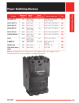
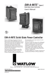
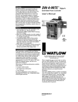
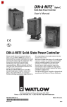
DIN-A-MITE ® C TOTAL CUSTOMER SATISFACTIO N 3 Ye ar Warranty SCR Power Controller Delivers Up To 80 Amperes in a Compact Package The DIN-A-MITE® C silicon controlled rectifier (SCR) power controller provides a low cost, compact and versatile solid state option for controlling electric heat. This controller is designed and manufactured with the quality features expected from Watlow®. DIN-rail/panel mount and through-wall mount versions are available. Features and Benefits Features include single-phase, three-phase/two leg, and three-phase/three leg, 24-600VAC operation. Current switching capabilities range from 30 to 80A depending on the model ordered. Compact size • Reduces panel space and cost Variable time-base, linear voltage and current process control or VAC/VDC input contactor versions are available. Single-phase, phase angle firing and current limiting are also available. All options are model number dependent and factory configurable. This power controller includes 200KA short circuit current rating (SCCR) tested up to 480VAC to minimize damage in the event of a short circuit when used with required fusing. 200KA SCCR with proper fusing • Minimizes damage in the event of a short circuit DIN-rail, panel and through-wall mounting • Provides versatility and quick, low-cost installation Touch-safe terminals • Increases safety for installer/user One- and three-phase power • Can be used in a variety of applications Open heater/shorted output alarm • Notifies the user in case of an open heater or shorted output Mercury free • Assures environmental safety Faster switching with solid state • Saves energy and extends heater life UL® 508 listed, C-UL®, RoHS 2 and CE with filter • Meets applications requiring agency approval • Reduces end product documentation cost System solution component • Provides single source thermal loop Back-to-back SCR design • Ensures a rugged design ® WIN-DMC-0115 © 2015 Watlow Electric Manufacturing Company all rights reserved. Specifications Operator Interface • Control input and indication light • Alarm output and indication light • Current limit indication LED Amperage Rating • See output rating curves on the next page • Max. surge current for 16.6ms, 1,350A peak • Max. I2t for fusing is 9100A2s • Latching current: 200mA min. • Holding current: 100mA min. • Fan current: 0.14A for 24VDC; 0.12A for 120VAC; 0.06A for 240VAC • Off-state leakage 1mA at 77°F (25°C) max. • Power dissipation: 1 watt per ampere per leg switched • 200KA SCCR, Type 1 and 2 approved with the recommended fusing; see user manual Line Voltage • 24 to 48VAC units: 20.4VAC min. to 53VAC max. • 100 to 240VAC units: 48VAC min. to 265VAC max. • 277 to 600VAC units: 85VAC min. to 660VAC max. • 100 to 120VAC, 200 to 208VAC, 230 to 240VAC, 277VAC, 400VAC, 480VAC, 600VAC, +10/-15%, 50 to 60Hz independent ±5% (control options L, P and S) Alarms (zero cross models only) Shorted SCR Alarm Option •Alarm state when the input command signal is off and a 10A or more load current is detected by the current transformer (two turns required for 5A and three turns for 2.5A) Open Heater Alarm Option (Control Option S only) •Alarm state when the input command signal is on and the load current detected by the current transformer is 20% less than customer adjusted set point Alarm Output •Energizes on alarm, non-latching •Triac 24 to 240VAC, external supply with a current rating of 300mA @ 77°F (25°C), 200mA @ 122°F (50°C), 100mA @ 176°F (80°C) and a holding current of 200µA with a latching current of 5mA typical Agency Approvals • CE with proper filter: 204/108/EC electromagnetic compatibility directive EN 61326-1: industrial immunity Class A emissions not suitable for Class B environments Control Input Terminals • Compression: will accept 24 to 16 AWG (0.2 to 1.5 mm2) wire • Torque to 4.4 in. lb (0.5 Nm) max. with a 1/8 in. (3.5 mm) blade screwdriver Line and Load Terminals • Compression: will accept 14 to 3 AWG (2.5 to 25 mm2) wire • Torque to 24 in. lb (2.7 Nm) max. with a 1/4 in. (6.4 mm) blade screwdriver, or a type 1A, #2 Pozi driver Operating Environment • See the output rating curve chart on next page • 0 to 90% RH (relative humidity), non-condensing • Storage temperature: -40 to 185°F (-40 to 85°C) • Operating temperature: -29 to 176°F (-34 to 80°C) • Insulation tested to 3,000 meters DIN-Rail Mount • DIN EN 50022, 35 mm by 7.5 mm Back-Panel Mount • Four mounting holes No. 6 to No. 8 (M3 to M4) fastener Through-Wall Mount • See page 4 for through-wall panel cutout (Note: Mount cooling fins vertically.) Additional Specifications for Contactors and Time Proportional Controllers Control Mode, Zero-Cross • Control option C: VDC input, contactor output • Control option K: VAC input, contactor output • To increase service life on contactor models, the cycle time should be less than three seconds • Control option F: 4 to 20mA DC input, variable time-base control output Control Input • AC contactor: 24VAC ±10%, 120VAC +10/-25%, 240VAC +10/-25% @ 25mA max. per controlled leg • DC contactor: 4.5 to 32VDC: max. c urrent @ 4.5VDC is 6mA per leg, add 2mA per LED used to the total current • Loop-powered linear current 4 to 20mA DC: loop-powered, control option F0 only, no more than three inputs connected in series Phase angle and phase angle with current limit (control options P and L) are not CE approved for conducted or radiated emissions 2006/95/EC low voltage directive EN 50178 safety requirements installation category III, pollution degree 2 •UL® 50 Type 4X enclosure, Class 1, Div. 2 per ANSI/ISA 12.12.01. Through-wall heat sink models T4 File 184390 • UL® 508 listed and C-UL® File E73741 • 2011/65/EU RoHS 2 • Shock and vibration tested to IEC 60068-2-32 • Vibration tested to IEC 60068-2-6 2 85 Natural Convection 80 75 70 65 60 25 0 5 10 15 20 25 30 35 40 45 50 55 60 65 70 75 80 Current (Amperes) into a Resistive Load DIN-A-MITE Style C Ratings at 100% On 80 70 65 Fan-Cooled e 2 g g le le 3 40 as e, e, 45 -Ph as as ph 50 ph 3- 55 gle Sin 60 3- Max. Internal Enclosure Ambient Temperature (°C) 75 35 30 25 0 5 10 15 20 25 30 35 40 45 50 55 60 65 70 75 80 85 90 Current (Amperes) into a Resistive Load DIN-A-MITE Style C Ratings at 100% On 80 Recommended Max. Enclosure Temperature is 176°F (80°C) 75 70 65 Through-Wall Heat Sink Si 60 e 35 g le ,3 se ha 40 2 e, 45 as Ph le- ng 50 as Ph 3- 55 3-P leg Ambient Air Around Heatsink Fins ( °C) Options • Manual control kit (1kΩ potentiometer) 08-5362 • Alarm option is not available on control options P or L Specifications are subject to change without notice. se Soft Start (Control Options P and L) Typically: • 5 seconds soft start on power up • Soft start on thermostat overtemperature • Soft start on 1/2 cycle drop out detection • 1 second soft start on set point change a Ph 35 Linearity (Control Option S) • ±5% input to output power over 0 to 100% of span between calibration points Resolution • Better than 0.1% of input span with respect to output change leg leg 40 ,2 45 ase e, 3 has 50 30 Output Voltage • 100 to 120VAC, 200 to 208VAC, 230 to 240VAC, 277VAC, 400VAC, 480VAC and 600VAC, ±10% Linearity (Control Options P and L) • ±5% input to output power, as referenced to a sinusoidal power curve, between calibration points le- 55 h 3-p 3-p Control Input • 0 to 20mA, 4 to 20mA, 0 to 5VDC, 1 to 5VDC and 0 to 10VDC • Input impedance 250Ω for 4mA to 20mA, 5kΩ for linear voltage input DIN-A-MITE Style C Ratings at 100% On 90 ng Si Operation • With control option S (single-cycle, variable time-base) the output is not on for more than one consecutive AC cycle below 50% power and not off for more than one consecutive AC cycle above 50% power • Phase angle control, single-phase only Output Rating Curves Max. Internal Enclosure Ambient Temperature (°C) Additional Specifications for Phase Angle, Phase Angle with Current Limit, and Single-Cycle, Variable Time-Base 30 25 0 5 10 15 20 25 30 35 40 45 50 55 60 65 70 75 80 Current (Amperes) into a Resistive Load 3 Side Dimensions—Natural Convection, DIN-rail/Panel Mount Side Front 1.51 in. (38 mm) 1.81 in. (46 mm) 2.11 in. (54 mm) Allowance for No. 8 Fastener (M4) 1 2 Top 4 in. (102 mm) Clearance for Air Flow and Wire Bending Radius 5.74 in. (146 mm) 4 in. (102 mm) 5.59 in. (142 mm) 1.73 in. 2.26 in. (44 mm) (57 mm) 3 5.89 in. (150 mm) 5 in. (127 mm) 5.17 in. (131 mm) DIN-EN 50022 35 by 7.5 mm Rail (Clipping Distance = 1.366 to 1.390 in. [34.7 to 35.3 mm]) 5.45 in. (138 mm) 3.42 in. (87 mm) 4 5 3.10 in. (79 mm) 5.74 in. (146 mm) Ground Wire Entry Rail Release Tab (pull down) 4 in. (102 mm) min. 4 in. (102 mm) Clearance for Air Flow and Wire Bending Radius 6 3.25 in. (83 mm) Front Panel is Touch-Safe, No Clearance is Required 1.89 in. (48 mm) Allowance for No. 8 Fastener (M4) Dimensions—Fan Cooled, DIN-rail/Panel Mount Side Side 4 in. (102 mm) Clearance for Air Flow and Wire Bending Radius 5.74 in. (146 mm) 4 in. (102 mm) 5.59 in. (142 mm) 1.73 in. (44 mm) 2.26 in. (57 mm) 5.89 in. (150 mm) 5.17 in. (131 mm) 3.10 in. (79 mm) 5 in. (127 mm) 7.64 in. (194 mm) Rail Release Tab (pull down) Front Panel is Touch-Safe, No Clearance is Required. 4 in. (102 mm) min. 4 in. (102 mm) Clearance for Air Flow and Wire Bending Radius Front Top Dimensions—Natural Convection, Through-Wall Mounta Front Top Panel Cutout Drill 0.228 in. (5.8 mm) (8) 4 in. (102 mm) Min. Clearance for Air Flow (Top and Bottom) Panel Opening Outline 8 ea M5-0.8 x 10 mm M5 Internal Tooth Lock Washers Included 4.81 in. (122 mm) 1 2 3 Ground Lug (2-8 Gauge) 2.25 in. (57 mm) Outside (Any Gauge) Sheet Metal (12 Ga.) 5 4.50 in. (114 mm) Heat Sink Outline 0.375 in. (9.5 mm) Reference 0.425 in. (10.8 mm) 1.625 in. (41.3 mm) 2.17 in. (55 mm) Inside (12 Gauge) 7 in. (178 mm) 4 Typical Panel Opening 4.625 in. (117.5 mm) Front Panel is Touch-Safe, No Clearance is Required 5.850 in. (148.6 mm) 6 0.4 in. (10 mm) Min. Clearance for Air Flow (Both Sides) aWith the potential for high through-wall heat sink temperatures, 6.375 in. (161.9 mm) 0.338 in. (8.6 mm) Reference 0.275 in. (7.0 mm) 1.034 in. (26.3 mm) 3.103 in. (78.8 mm) 3.862 in. (98.1 mm) 4.137 in. (105.1 mm) application may require a touch-safe shield. 4 Extended Heater and Power Controller Life with Variable Time-Base Single-Cycle, Variable Time-Base Output With variable time-base control, the power controller automatically adjusts the time-base and output power with respect to the command signal. Accelerated life testing shows that variable time-base control significantly reduces expansion and contraction of the heater element. This extends heater and power controller life while improving process temperature control. This saves money on heaters, downtime and maintenance. 25% Power Output: 1 AC cycle on, 3 cycles off Loop-Powered or Transformer Powered Loop-Powered By using a temperature controller’s 4-20mA process output signal as the power supply for the DIN-A-MITE input, the cost of the power controller can be reduced. With control option F0 the 4-20mA control signal simultaneously powers the DIN-A-MITE’s internal electronics and provides the input command signal. Models: DC_ _ - _ _S_ - _ _ _ _ 50% Power Output: 1 AC cycle on, 1 cycle off With single-cycle, variable time-base control, at 50 percent power, the output is on for one cycle and off for one cycle. At 25 percent, it is on for one cycle and off for three cycles. Under 50 percent, the output is not on for more than one consecutive cycle; over 50 percent the output is not off for more than one consecutive cycle. Semiconductor Fuses for Applications through 600VAC Fuse Part Number Transformer-Powered DIN-A-MITE controllers with single-cycle, variable time-base or phase angle outputs (control options L, P and S) detect the power line zero cross with a transformer that also powers their internal electronics. These units can be controlled manually with a potentiometer or automatically with a temperature controller using any of the control options: 4-20mA, linear voltage (0-5,1-5 and 0-10VDC). Loop-Powered, Variable Time-Base Output Models: DC_ _ - _ _F0 - _ _ _ _ 20% Power Output: 3 AC cycles on, 12 cycles off 50% Power Output: 3 AC cycles on, 3 cycles off Fuse Rating 40A 50A 63A 80A 100A Watlow 17-8040 17-8050 17-8063 17-8080 17-8100 Cooper Bussman® FWP-40A14F FWP-50A14F FWP-63A22F FWP-80A22F FWP-100A22F Fuse Holder Part Number Fuse Rating 40A 50A 63A 80A 100A Watlow 17-5114 17-5114 17-5122 17-5122 17-5122 Ferraz Shawmut US141I US141I US221I US221I US221I Combined Branch Protection and Semiconductor Fuses for Applications through 480VAC Fuse Part Number 80% Power Output: 12 AC cycles on, 3 cycles off With loop-powered, variable time-base control, the minimum on or off time is three cycles. Phase Angle Output Models: DC1_ - _ _ [L, P] _ - 0_ _ _ Fuse Rating 125% of Load 20A 30A 40A 50A 63A 80A 100A Watlow 0808-0325-0020 0808-0325-0030 0808-0325-0040 0808-0325-0050 0808-0325-0060 0808-0325-0080 0808-0325-0100 Cooper Bussman® DFJ-20 DFJ-30 DFJ-40 DFJ-50 DFJ-60 DFJ-80 DFJ-100 Fuse Holder Part Number Phase angle control (control options L and P) is infinitely variable over the period of the AC sine wave. It provides a variable voltage and/or current output. The phase angle circuitry is transformer powered and accepts a linear voltage, current or potentionmeter input. Fuse Rating 0 and 30A 2 40 to 63A 80 and 100A Watlow 0808-0326-1530 0808-0326-3560 0808-0326-7010 Cooper Bussman® CH30J1i CH60J1i J601001CR 5 Ordering Information Part Number ① ② ③ Phase ④ Cooling & Current Rating/Leg C D - ⑤⑥ Line & Load Voltage ⑦⑧ ⑨ ⑩ ⑪ ⑫ Control Alarm User Manual Custom Options ③ 1= 2= 3= 8= 9= Phase 1-phase, 1 controlled leg 3-phase, 2 controlled legs 3-phase, 3 controlled legs (use with four wire wye) 2 independent zones (control options C, K) 3 independent zones (control options C, K) ④ 0= 1= 2= 3= T= Cooling and Current Rating per Leg (see chart below) Natural convection standard DIN-rail or panel heat sink Fan cooled 120VAC standard DIN-rail or panel heat sink Fan cooled 240VAC standard DIN-rail or panel heat sink Fan cooled 24VDC standard DIN-rail or panel heat sink Natural convection through-wall or cabinet heat sink (NEMA 4X) ⑤ ⑥ Line and Load Voltage 24 to 48VAC (control options C, F, K) 100 to 120VAC (control options L, P, S) 200 to 208VAC (control options L, P, S) 100 to 240VAC (control options C, F, K): 230 to 240VAC (control options L, P, S) 277VAC (control options L, P, S) 400VAC (control options L, P, S) 480VAC (control options L, P, S) 277 to 600VAC (control options C, F, K): 600VAC (control options L, P, S) 02= 12= 20= 24= 27= 40= 48= 60= - ⑦⑧ C0= F0= K1= K2= K3= L (0 to 5)= Control 4.5 to 32VDC input, contactor output 4 to 20mA DC input, variable time-base output 22 to 26VAC input, contactor output 100 to 120VAC input, contactor output 200 to 240VAC input, contactor output Phase angle output with current limiting* (single-phase only) P (0 to 5)= Phase angle output* (single-phase only) S (0 to 5)= Single-cycle variable time-base output 0 = 4 to 20mA input 1 = 12 to 20mA input (option S only) 2 = 0 to 20mA input 3 = 0 to 5VDC input 4 = 1 to 5VDC input 5 = 0 to 10VDC input * Not CE approved for conducted or radiated emissions. ⑨ 0= S= H= Alarm No alarm Shorted SCR alarm (not available with control options L or P) Open-heater and shorted-SCR alarm (control option S only) ⑩ 0= 1= 2= 3= User Manual English German Spanish French ⑪ ⑫ Custom Options 00= Standard part 1X= 1-second soft start (control options P, L) XX= Any letter or number, custom options, labeling, etc. DIN-A-MITE C Current Rating Table Phase 1 1 1 2, 8 2, 8 2, 8 3, 9 3, 9 3, 9 Cooling 0 T 1, 2, 3 0 T 1, 2, 3 0 T 1, 2, 3 Current at 122˚F (50˚C) 55A 60A 75A 40A 46A 65A 30A 35A 55A Watlow® and DIN-A-MITE® are registered trademarks of Watlow Electric Manufacturing Company. UL® and C-UL® are registered trademarks of the Underwriter’s Laboratories, Inc. Cooper Bussmann® is a registered trademark of Cooper Bussmann, Inc. To be automatically connected to the nearest North American Technical Sales Office: 1-800-WATLOW2 • www.watlow.com • [email protected] International Technical Sales Offices: Australia, +61 3 9335 6449 • China, +86 21 3532 8532 • France, +33 (0) 1 41 32 79 70 Germany, +49 (0) 7253 / 9400-0 • India, +91 40 6661 2700 • Italy, +39 02 4588841 • Japan, +81 3 3518 6630 • Korea, +82 2 2169 2600 Malaysia, +60 3 8076 8745 • Mexico, +52 442 256 2200 • Singapore, +65 6773 9488 • Spain, +34 91 675 1292 Taiwan, +886 7 288 5168 • United Kingdom, +44 (0) 115 964 0777 6