1
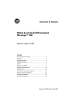
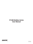
Installation Instructions
SLC 500™ RTD/Resistance Input Module
(Catalog Number 1746-NR8)
Inside…
page
Important User Information ..................................................................... 2
For More Information ............................................................................... 3
Hazardous Location Considerations ....................................................... 4
Environnements dangereux .................................................................... 4
Hazardous Location Considerations ........................................................ 4
Required Tools and Equipment ................................................................ 6
Electrostatic Damage............................................................................... 7
Power Requirements................................................................................ 7
Modular Chassis Considerations............................................................. 8
Fixed Expansion Chassis Considerations................................................. 8
General Considerations ........................................................................... 8
Module Installation and Removal............................................................ 9
Terminal Block Wiring and Removal...................................................... 10
Wiring Considerations ........................................................................... 11
Wiring Resistance Devices (Potentiometers) to the Module ................ 14
Wiring Input Devices to the NR8 Module ............................................. 15
Specifications ........................................................................................ 16
Publication 1746-IN007C-EN-P - December 2002
2
SLC 500™ RTD/Resistance Input Module
Important User Information
Because of the variety of uses for the products described in this publication, those
responsible for the application and use of this control equipment must satisfy
themselves that all necessary steps have been taken to assure that each application
and use meets all performance and safety requirements, including any applicable
laws, regulations, codes and standards.
The illustrations, charts, sample programs and layout examples shown in this guide
are intended solely for purposes of example. Since there are many variables and
requirements associated with any particular installation, Allen-Bradley does not
assume responsibility or liability (to include intellectual property liability) for actual
use based upon the examples shown in this publication.
Allen-Bradley publication SGI-1.1, Safety Guidelines for the Application,
Installation, and Maintenance of Solid-State Control (available from your local
Allen-Bradley office), describes some important differences between solid-state
equipment and electromechanical devices that should be taken into consideration
when applying products such as those described in this publication.
Reproduction of the contents of this copyrighted publication, in whole or in part,
without written permission of Allen-Bradley Company, Inc., is prohibited.
Throughout these installation instructions we use notes to make you aware of
safety considerations:
ATTENTION
Identifies information about practices or circumstances that
can lead to personal injury or death, property damage or
economic loss.
!
Attention statements help you to:
• identify a hazard
• avoid the hazard
• recognize the consequences
IMPORTANT
Identifies information that is critical for successful application
and understanding of the product.
Publication 1746-IN007C-EN-P - December 2002
SLC 500™ RTD/Resistance Input Module
3
For More Information
Related Publications
For
Refer to this Document
Pub. No.
A more detailed description on how to install
and use your RTD/Resistance Input Module.
SLC 500™ RTD/Resistance
Input Module User Manual
1746-UM003
A more detailed description on how to install
and use your modular SLC 500 system.
SLC 500™ Modular Hardware
Style Installation and Operation
Manual
1747-UM011
A more detailed description on how to install
and use your fixed SLC 500 system.
SLC 500™ Fixed Hardware
Style Installation and Operation
Manual
1747-6.21
A reference manual that contains status file
data, instruction set, and troubleshooting
information.
SLC 500™ Instruction Set
Reference Manual
1747-RM001
How to Get More Information
If you would like a manual, you can:
• download a free electronic version from the internet at
www.theautomationbookstore.com
• purchase a printed manual by:
– contacting your local distributor or Rockwell Automation representative
– visiting www.theautomationbookstore.com
and placing your order
– calling 1.800.963.9548 (USA/Canada) or 001.330.725.1547 (Outside
USA/Canada)
Publication 1746-IN007C-EN-P - December 2002
4
SLC 500™ RTD/Resistance Input Module
Hazardous Location Considerations
This equipment is suitable for use in Class I, Division 2, Groups A, B, C, D or
non-hazardous locations only. The following WARNING statement applies to use in
hazardous locations.
WARNING
!
EXPLOSION HAZARD
• Substitution of components may impair suitability for Class
I, Division 2.
• Do not replace components or disconnect equipment
unless power has been switched off.
• Do not connect or disconnect components unless power
has been switched off.
• All wiring must comply with N.E.C. article 501-4(b).
Environnements dangereux
Cet équipement est conçu pour être utilisé dans des environnements de Classe 1,
Division 2, Groupes A, B, C, D ou non dangereux. La mise en garde suivante
s’applique à une utilisation dans des environnements dangereux.
ATTENTION
!
DANGER D’EXPLOSION
• La substitution de composants peut rendre cet
équipement impropre à une utilisation en
environnement de Classe 1, Division 2.
• Ne pas remplacer de composants ou déconnecter
l'équipement sans s'être assuré que l'alimentation est
coupée.
• Ne pas connecter ou déconnecter des composants sans
s'être assuré que l'alimentation est coupée.
Publication 1746-IN007C-EN-P - December 2002
SLC 500™ RTD/Resistance Input Module
5
Overview
The RTD (Resistance Temperature Detector) module receives and stores digitally
converted analog data from RTDs or other resistance inputs such as potentiometers
into its image table for retrieval by all fixed and modular SLC 500 processors. An
RTD consists of a temperature-sensing element connected by 2, 3 or 4 wires that
provide input to the RTD module. The module supports connections from any
combination of up to eight RTDs of various types (for example: platinum, nickel,
copper, or nickel-iron) or other resistance inputs. See the input specifications
beginning on page 19 for RTD types, their associated temperature ranges, and the
analog input signal ranges that each 1746-NR8 channel supports. Each input
channel is individually configurable for a specific input device. Broken sensor
detection (open- or short-circuit) is provided for each input channel. In addition,
the module provides indication if the input signal is out-of-range.
The module contains a removable terminal block providing connection for any mix
of eight RTD sensors or resistance input devices. There are no output channels on
the module. Module configuration is done via the user program. There are no DIP
switches.
Channel Status LEDs
Channel status LEDs indicate the status for channels 0 through 7. Related error
information is contained in the channel status word. This includes conditions such
as:
•
•
•
•
normal operation
channel-related configuration errors
open-circuit errors
out-of-range errors
All channel errors are recoverable errors.
Module Status LED
The module status LED shows diagnostic or operating errors related to the module.
These non-recoverable errors may be detected during power-up or during
operation. Once an error has been detected, the module no longer communicates
with the SLC processor. Channel states are disabled and data words are cleared (0).
Failure of any diagnostic test results in a non-recoverable error and requires the
assistance of your local distributor or Rockwell Automation.
Publication 1746-IN007C-EN-P - December 2002
6
SLC 500™ RTD/Resistance Input Module
Channel Status
LEDs (Green)
INPUT
CHANNEL
STA TUS
0
1
2
3
MODULE
RTD / resistance
4
5
6
7
Module Status
LED (Green)
Removable Terminal
Block
Door Label
RTD 0
Sense 0
Return 0
RTD 1
Sense 1
Return 1
RTD 2
Sense 2
Return 2
RTD 3
Sense 3
Return 3
RTD 4
Sense 4
Return 4
RTD 6
Sense 5
Return 5
RTD 6
Sense 6
Return 6
RTD 7
Sense 7
Return 7
1746-NR8
Cable Tie Slots
Required Tools and Equipment
Have the following tools and equipment ready
•
•
•
•
•
small blade screwdriver (0.100 inch slot width)
RTD module (1746-NR8)
RTD sensor or resistance input
appropriate cable (if needed)
programming equipment
Publication 1746-IN007C-EN-P - December 2002
SLC 500™ RTD/Resistance Input Module
7
Electrostatic Damage
Electrostatic discharge can damage semiconductor devices inside this module if you
touch backplane connector pins or other sensitive areas. Guard against electrostatic
damage by observing the following precautions.
ATTENTION
Electrostatic discharge can degrade performance or cause
permanent damage. Handle the module as stated below.
!
• Wear an approved wrist strap grounding device when handling the module.
• Touch a grounded object to rid yourself of electrostatic charge before
handling the module.
• Handle the module from the front, away from the backplane connector. Do
not touch backplane connector pins.
• Keep the module in its static-shield bag when not in use, or during
shipment.
Power Requirements
The RTD module receives its power through the SLC 500 chassis backplane from
the fixed or modular +5V dc/+24V dc chassis power supply. The maximum current
drawn by the module is shown in the table below.
5V dc Amps
24V dc Amps
0.100
0.055
When you are using a modular system configuration, add the values shown in the
table above to the requirements of all other modules in the SLC chassis to prevent
overloading the chassis power supply.
When you are using a fixed system controller, refer to the important note on page 8
about module compatibility in a 2-slot fixed expansion chassis.
Publication 1746-IN007C-EN-P - December 2002
8
SLC 500™ RTD/Resistance Input Module
Modular Chassis Considerations
Place your RTD module in any slot of an SLC 500 modular chassis (except slot 0) or
a modular expansion chassis. Slot 0 is reserved for the modular processor or
adapter module.
Fixed Expansion Chassis Considerations
IMPORTANT
The 2-slot, SLC 500 fixed I/O expansion chassis (1746-A2)
supports many combinations of modules. The combinations
that are not supported by the fixed expansion chassis are
shown in the table below. For a complete listing of valid
combinations using the RTD module in a 2-slot expansion
chassis with another SLC I/O or communication module, refer
to the table in the SLC 500™ RTD/Resistance Input Module
User Manual.
For a complete listing of valid combinations using the RTD module in a 2-slot
expansion chassis with another SLC I/O or communication module, refer to the
table in the SLC 500 RTD/Resistance Input Module User Manual, publication
number 1746-UM003.
General Considerations
Most applications require installation in an industrial enclosure to reduce the effects
of electrical interference. RTD inputs are susceptible to electrical noises due to the
small amplitudes of their signal.
Group your modules to minimize adverse effects from radiated electrical noise and
heat. Consider the following conditions when selecting a slot for the RTD module.
Position the module:
• in a slot away from power lines, load lines and other sources of electrical
noise such as hard-contact switches, relays, and AC motor drives
• away from modules which generate significant radiated heat, such as the
32-point I/O modules
Publication 1746-IN007C-EN-P - December 2002
SLC 500™ RTD/Resistance Input Module
9
Module Installation and Removal
When installing the module in a chassis, it is not necessary to remove the terminal
block from the module.
Module Installation Procedure
1. Align the circuit board of the RTD module with the card guides located at
the top and bottom of the chassis.
2. Slide the module into the chassis until both top and bottom retaining clips
are secured. Apply firm even pressure on the module to attach it to its
backplane connector. Never force the module into the slot.
3. Cover all unused slots with the Card Slot Filler, Catalog Number 1746-N2.
Top and Bottom
Module Release(s)
Card
Guide
Module Removal Procedure
1. Press the releases at the top and bottom of the module and slide the module
out of the chassis slot.
2. Cover all unused slots with the Card Slot Filler, Catalog Number 1746-N2.
Publication 1746-IN007C-EN-P - December 2002
10
SLC 500™ RTD/Resistance Input Module
Terminal Block Wiring and Removal
The RTD module contains an 24-position, removable terminal block. The terminal
pin-out is shown below.
ATTENTION
!
Disconnect power to the SLC before attempting to install,
remove, or wire the removable terminal wiring block.
To avoid cracking the removable terminal block, alternate the
removal of the terminal block release screws.
Terminal Wiring
Terminal screws accept a maximum of one #14 AWG (2 mm2) wire. Tighten
terminal screws only tight enough to immobilize wires. Maximum torque on
terminal screws is 0.25 Nm (2.25 in-lb.).
RTD 0
Sense 0
Return 0
RTD 1
Sense 1
Return 1
RTD 2
Sense 2
Return 2
RTD 3
Sense 3
Return 3
RTD 4
Sense 4
Return 4
RTD 5
Sense 5
Return 5
RTD 6
Sense 6
Return 6
RTD 7
Sense 7
Release Screw Max Torque = 0.25 Nm (2.25 in-lb)
Publication 1746-IN007C-EN-P - December 2002
SLC 500™ RTD/Resistance Input Module
11
Terminal Block Removal
If the terminal block is removed, use the write-on label located on the side of the
terminal block to identify the module location and type.
To remove the terminal block:
1. Loosen the two terminal block release screws.
2. Grasp the terminal block at the top and bottom and pull outward and down.
Wiring Considerations
Follow the guidelines below when planning your system wiring.
Since the operating principle of the RTD module is based on the measurement of
resistance, take special care in selecting your input cable. For 2-wire or 3-wire
configuration, select a cable that has a consistent impedance throughout its entire
length.
Configuration
Recommended Cable
2-wire
Belden™ #9501 or equivalent
3-wire
less than 30.48 m (100 ft.)
Belden #9533 or equivalent
3-wire
greater than 30.48 m (100 ft.) or high humidity conditions
Belden #83503 or equivalent
For a 3-wire configuration, the module can compensate for a maximum cable
length associated with an overall cable impedance of 25 ohms.
As shown in the figure on the next page, three configurations of RTDs can be
connected to the RTD module:
• 2-wire RTD, which is composed of 2 RTD lead wires (RTD and Return)
• 3-wire RTD, which is composed of a Sense and 2 RTD lead wires (RTD and
Return)
• 4-wire RTD, which is composed of 2 Sense and 2 RTD lead wires (RTD and
Return). The second sense wire of a 4-wire RTD is left open.
Publication 1746-IN007C-EN-P - December 2002
12
SLC 500™ RTD/Resistance Input Module
2 Wire Interconnection
Cable Shield
(Frame Ground)
Add
Jumper
RTD
Return
Belden #9501 Shielded Cable
RTD 0
Sense 0
Return 0
RTD 1
Sense 1
Return 1
RTD 2
Sense 2
Return2
3 Wire Interconnection
Cable Shield (Frame
Ground)
RTD
Sense
Return
Belden #9533 Shielded Cable or
Belden #83503 Shielded Cable
RTD 0
Sense 0
Return 0
RTD 1
Sense 1
Return 1
RTD 2
Sense 2
Return2
4 Wire Interconnection
Cable Shield (Frame
Ground)
RTD
Sense
Return
Leave One Sensor Wire Open
Belden #9533 Shielded Cable or
Belden #83503 Shielded Cable
Publication 1746-IN007C-EN-P - December 2002
RTD 0
Sense 0
Return 0
RTD 1
Sense 1
Return 1
RTD 2
Sense 2
Return2
RTD 0
Sense 0
Return 0
RTD 1
Sense 1
Return 1
RTD 2
Sense 2
Return2
RTD 3
Sense 3
Return 3
RTD 4
Sense 4
Return 4
RTD 5
Sense 5
Return 5
RTD 6
Sense 6
Return 6
RTD 7
Sense 7
Return 7
SLC 500™ RTD/Resistance Input Module
IMPORTANT
13
The RTD module requires three wires to compensate for lead
resistance error. We recommend that you do not use 2-wire
RTDs if long cable runs are required, as it reduces the
accuracy of the system. However, if a 2-wire configuration is
required, reduce the effect of the lead wire resistance by using
a lower gauge wire for the cable (for example, use AWG #16
instead of AWG #24). Also, use cable that has a lower
resistance per foot of wire. The module’s terminal block
accepts one AWG #14 gauge wire.
• To limit overall cable impedance, keep input cables as short as possible.
Locate your I/O chassis as near the RTD sensors as your application permits.
• Ground the shield drain wire at one end only. The preferred location is at
the chassis mounting tab of the chassis, under the RTD module. Refer to
IEEE Std. 518, Section 6.4.2.7 or contact your sensor manufacturer for
additional details.
• Route RTD/resistance input wiring away from any high-voltage I/O wiring,
power lines, and load lines.
• Tighten terminal screws using a small flathead screwdriver. Each screw
should be turned tight enough to immobilize the wire’s end. Excessive
tightening can strip the terminal screw. The torque applied to each screw
should not exceed 0.25 Nm (2.25 in-lb.) for each terminal.
• Follow system grounding and wiring guidelines found in your SLC 500
Installation and Operation Manual, publication 1747-UM011.
When using a 3-wire configuration, the module compensates for resistance error
due to lead wire length. For example, in a 3-wire configuration, the module reads
the resistance due to the length of one of the wires and assumes that the resistance
of the other wire is equal. If the resistances of the individual lead wires are much
different, an error may exist. The closer the resistance values are to each other, the
greater the amount of error that is eliminated.
IMPORTANT
To ensure temperature or resistance value accuracy, the
resistance difference of the cable lead wires must be equal to
or less than 0.01Ω.
There are several ways to insure that the lead values match as closely as possible.
They are as follows:
• Keep lead resistance as small as possible and less than 25Ω .
• Use quality cable that has a small tolerance impedance rating.
• Use a heavy-gauge lead wire which has less resistance per foot.
Publication 1746-IN007C-EN-P - December 2002
14
SLC 500™ RTD/Resistance Input Module
Wiring Resistance Devices (Potentiometers) to the Module
Potentiometer wiring requires the same type of cable as that for the RTD described
on page 11. Potentiometers can be connected to the RTD module as a 2-wire
interconnection as shown below.
2 Wire Potentiometer Interconnection
Add Jumper
Potentiometer
Cable Shield (Frame
Ground)
Belden #9501 Shielded Cable
Cable Shield (Frame
Ground)
Potentiometer
Belden #9501 Shielded Cable
Publication 1746-IN007C-EN-P - December 2002
Add Jumper
RTD 0
Sense 0
Return 0
RTD 1
Sense 1
Return 1
RTD 2
Sense 2
Return 2
RTD 3
Sense 3
Return 3
RTD 4
Sense 4
Return 4
RTD 5
Sense 5
Return 5
RTD 6
Sense 6
Return 6
RTD 7
RTD 0
Sense 0
Return 0
RTD 1
Sense 1
Return 1
RTD 2
Sense 2
Return 2
RTD 3
Sense 3
Return 3
RTD 4
Sense 4
Return 4
RTD 5
Sense 5
Return 5
RTD 6
Sense 6
Return 6
RTD 7
SLC 500™ RTD/Resistance Input Module
15
Wiring Input Devices to the NR8 Module
(See Step 4.)
2-Conductor Shielded Cable
Signal Wire
Signal Wire
Signal Wire
Foil Shield
Signal Wire
Drain Wire
(See step 3.)
Signal Wire
(See Step 4.)
Signal Wire
3-Conductor Shielded Cable
Signal Wire
Foil Shield
Drain Wire
Signal Wire
Signal Wire
Signal Wire
(See step 3.)
To wire your NR8 module, follow these steps.
1. At each end of the cable, strip some casing to expose the individual wires.
2. Trim the signal wires to 5.08-cm (2-in.) lengths. Strip about 4.76 mm (3/16
in.) of insulation away to expose the end of the wire.
3. At one end of the cable twist the drain wire and foil shield together, bend
them away from the cable, and apply shrink wrap. Then earth ground at the
frame ground of the chassis.
4. At the other end of the cable, cut the drain wire and foil shield back to the
cable and apply shrink wrap.
5. Connect the signal wires to the 1746-NR8 terminal block and the input.
6. Repeat steps 1 through 5 for each channel on the 1746-NR8 module.
Publication 1746-IN007C-EN-P - December 2002
16
SLC 500™ RTD/Resistance Input Module
Specifications
Electrical Specifications
Backplane Current Consumption
100 mA at 5V dc
55 mA at 24V dc
Backplane Power Consumption
1.82W maximum (0.5W at 5V dc, 1.32W at 24V dc)
External Power Supply Requirements
None
Number of Channels
8 (backplane isolated)
I/O Chassis Location
Any I/O module slot except slot 0
A/D Conversion Method
Sigma-Delta Modulation
Input Filtering
Low pass digital filter with programmable notch (filter)
frequencies
Common Mode Rejection
(28 Hz and 50/60 Hz Filter frequencies)
> 120 dB at 50 Hz (28 Hz and 50 Hz filter frequencies)
> 120 dB at 60 Hz (28 Hz and 60 Hz filter frequencies)
Normal Mode Rejection
(between [+] input and [-] input)
65 dB minimum at 50/60 Hz with 50/60 Hz filter
110 dB minimum at 50 Hz with 28 Hz filter
95 dB minimum at 60 Hz with 28 Hz filter
Max. common mode voltage
Max. allowed permanent overload
±1 volt
(1)
Volts = ±5V dc; Current = ±5 mA
Input Filter Cut-Off Frequencies
7.80 Hz at 28 Hz filter frequency
13.65 Hz at 50/60 Hz filter frequency
209.6 Hz at 800 Hz filter frequency
1676 Hz at 6400 Hz filter frequency
Calibration
Module autocalibrates at power-up. Periodic calibration (every
5 minutes) can also be enabled.
Isolation
500V ac for 1 minute between inputs and chassis ground, and
between inputs and backplane.
5V dc continuous between channels.
(1)
Do not apply a voltage or current to the module.
Publication 1746-IN007C-EN-P - December 2002
SLC 500™ RTD/Resistance Input Module
17
Physical Specifications
LED Indicators
Module ID Code
Maximum Termination Wire Size
Maximum Cable Impedance
Terminal Block
9 green status indicators, one for each of 8 channels and one for module
status
3508 - Class 1
12708 - Class 3
One 14 AWG wire per terminal
25 ohms maximum impedance for 3-wire RTD configuration (see Cable
Specifications on page 11.)
1746-RT-35
Environmental Specifications
Operating Temperature
0°C to +60°C (+32°F to +140°F)
Storage Temperature
-40°C to +85°C (-40°F to +185°F)
Relative Humidity
5% to 95% (without condensation)
Agency Certification
UL and C-UL approved
Hazardous Environment Classification
Class I, Division 2 Hazardous Environment Groups A, B, C, D
EMC
CE compliant for all applicable directives
C-Tick compliant for all applicable acts
Publication 1746-IN007C-EN-P - December 2002
18
SLC 500™ RTD/Resistance Input Module
Input Specifications
RTD Types
platinum, nickel, nickel iron, copper
(For additional information on RTD types, see page 21.)
Temperature
°C or °F and 0.1°C or 0.1°F
Scale (Selectable)
Resistance Scale
(Selectable)
1Ω or 0.1Ω for all resistance ranges except for 150Ω; or 0.1Ω or 0.01Ω for 150Ω
potentiometer.
Input Step
Response
Refer to the SLC 500™ RTD/Resistance Input Module User Manual, publication number
1747-UM003A.
Channel Turn-On
Time
Requires up to one module update time plus module calibration time.
Channel Turn-Off
Time
Requires up to one module update time.
Reconfiguration
Time
Requires up to one module update time plus module calibration time.
Channel Scan
Time (with lead
resistance)
28 Hz = 250 ms
50/60 Hz = 147 ms
800 Hz = 18 ms
6400 Hz = 10 ms
Channel Scan
28 Hz = 125 ms
Time (without lead 50/60 Hz = 75 ms
resistance)
800 Hz = 10 ms
6400 Hz = 6 ms
RTD Excitation
Current
RTD setting:
0.25 mA - Recommended for use with higher resistance ranges for both RTDs and direct
resistance inputs (1000Ω RTDs and 3000Ω resistance input). Refer to RTD manufacturer for
recommendations.
1.0 mA -Recommended to use for all other RTD and direct resistance inputs, except 1000Ω
RTDs and 3000Ω resistance input ranges are limited. Refer to RTD manufacturer for
recommendations.
Publication 1746-IN007C-EN-P - December 2002
SLC 500™ RTD/Resistance Input Module
19
RTD Temperature Ranges, Resolution, and Repeatability
Input Type
Resolution
Repeatability
-200°C to +850°C
(-328°F to +1562°F)
0.1°C
(0.1°F)
±0.2°C
(±0.4°F)
-200°C to +850°C
(-328°F to +1562°F)
-200°C to +850°C
(-328°F to +1562°F)
0.1°C
(0.1°F)
±0.2°C
(±0.4°F)
-200°C to +850°C
(-328°F to +1562°F)
-200°C to +390°C
(-328°F to +698°F)
0.1°C
(0.1°F)
±0.2°C
(±0.4°F)
1000Ω -200°C to +850°C
(-328°F to +1562°F)
-200°C to +50°C
(-328°F to +122°F)
0.1°C
(0.1°F)
±0.2°C
(±0.4°F)
100Ω
-200°C to +630°C
(-328°F to +1166°F)
-200°C to +630°C
(-328°F to +1166°F)
0.1°C
(0.1°F)
±0.2°C
(±0.4°F)
200Ω
-200°C to +630°C
(-328°F to +1166°F)
-200°C to +630°C
(-328 °F to +1166°F)
0.1°C
(0.1°F)
±0.2°C
(±0.4°F)
500Ω
-200°C to +630°C
(-328°F to +1166°F)
-200°C to +380°C
(-328°F to +698°F)
0.1°C
(0.1°F)
±0.2°C
(±0.4°F)
1000Ω -200°C to +630°C
(-328°F to +1166°F)
-200°C to +50°C
(-328°F to +122°F)
0.1°C
(0.1°F)
±0.2°C
(±0.4°F)
10Ω
-100°C to +260°C
(-328°F to +500°F)
-100°C to +260°C
(-148°F to +500°F)
0.1°C
(0.1°F)
±0.2°C
(±0.4°F)
120Ω
-100°C to +260°C
(-328°F to +500°F)
-100°C to +260°C
(-328°F to +500°F)
0.1°C
(0.1°F)
±0.1°C
(±0.2°F)
Nickel
(672)(2)
120Ω
-80°C to +260°C
(-328°F to +500°F)
-80°C to +260°C
(-328°F to +500°F)
0.1°C
(0.1°F)
±0.1°C
(±0.2°F)
Nickel Iron
(518)(2)
604Ω
-200°C to +200°C
(-328°F to +392°F)
-200°C to +180°C
(-328°F to +338°F)
0.1°C
(0.1°F)
±0.1°C
(±0.2°F)
Platinum
(385)(2)
Platinum
(3916)(2)
Copper
(426)(2)
(3)
Nickel
(618)(2)
(4)
(1)
(2)
Temp. Range
(0.25 mA Excitation)(1)
Temp. Range
100Ω
-200°C to +850°C
(-328°F to +1562°F)
200Ω
500Ω
(1.0 mA Excitation)(1)
The temperature range for the 1000Ω RTD is dependent on the excitation current.
The digits following the RTD type represent the temperature coefficient of resistance (α), which is defined as the resistance
change per ohm per °C. For instance, Platinum 385 refers to a platinum RTD with
α = 0.00385 ohms/ohm - °C or simply 0.00385/°C.
(3)
Actual value at 0°C is 9.042Ω per SAMA standard RC21-4-1966.
(4)
Actual value at 0°C is 100Ω per DIN standard.
Publication 1746-IN007C-EN-P - December 2002
20
SLC 500™ RTD/Resistance Input Module
Input Type
Resistance
Resistance Range
(0.25 mA
Excitation)
Resistance Range
(1.0 mA Excitation)
Resolution
Repeatability
(28 Hz, 50/60 Hz)
150Ω
0 to 150Ω
0 to 150Ω
0.01Ω
±0.04Ω
500Ω
0 to 500Ω
0 to 500Ω
0.1Ω
±0.2Ω
1000Ω
0 to 1000Ω
0 to 1000Ω
0.1Ω
±0.2Ω
3000Ω
0 to 3000Ω
0 to 1200Ω
0.1Ω
±0.2Ω
The module accuracy is dependent on the RTD/Resistance type, the excitation
current, and the input filter selection. The following table shows the module
accuracy and temperature drift when the module has been auto-calibrated at the
operating temperature and when the module’s temperature changes but has not
been recalibrated.
Publication 1746-IN007C-EN-P - December 2002
SLC 500™ RTD/Resistance Input Module
21
RTD Accuracy and Temperature Drift Specifications
Input Type
Platinum
(385)(3)
Accuracy(1)
(0.25 mA
Excitation)
±0.5°C
(±0.9°F)
±0.6°C
(±1.1°F)
±0.7°C
(±1.3°F)
±1.2°C
(±2.2°F)
±0.4°C
(±0.7°F)
±0.5°C
(±0.9°F)
±0.6°C
(±1.1°F)
±0.9°C
(±1.6°F)
±0.5°C
(±0.9°F)
Accuracy(1)
(1.0 mA
Excitation)
±0.7°C
(±1.3°F)
±0.7°C
(±1.3°F)
±0.5°C
(±0.9°F)
±0.4°C
(±0.7°F)
±0.6°C
(±1.1°F)
±0.6°C
(±1.1°F)
±0.4°C
(±0.7°F)
±0.3°C
(±0.6°F)
±0.8°C
(±1.4°F)
Temperature Drift(2)
(0.25 mA Excitation)
Temperature Drift(2)
(1.0 mA Excitation)
±0.012°C/°C
(±0.012°F/°F)
±0.015°C/°C
(±0.015°F/°F)
±0.020°C/°C
(±0.020°F/°F)
±0.035°C/°C
(±0.035°F/°F)
±0.010°C/°C
(±0.010°F/°F)
±0.011°C/°C
(±0.011°F/°F)
±0.015°C/°C
(±0.015°F/°F)
±0.026°C/°C
(±0.026°F/°F)
±0.008°C/°C
(±0.008°F/°F)
±0.020°C/°C
(±0.020°F/°F)
±0.020°C/°C
(±0.020°F/°F)
±0.012°C/°C
(±0.012°F/°F)
±0.010°C/°C
(±0.010°F/°F)
±0.015°C/°C
(±0.015°F/°F)
±0.015°C/°C
(±0.015°F/°F)
±0.012°C/°C
(±0.012°F/°F)
±0.010°C/°C
(±0.010°F/°F)
±0.008°C/°C
(±0.008°F/°F)
±0.2°C
(±0.4°F)
±0.2°C
(±0.4°F)
±0.003°C/°C
(±0.003°F/°F)
±0.005°C/°C
(±0.005°F/°F)
±0.2°C
(±0.4°F)
±0.3°C
(±0.5°F)
±0.2°C
(±0.4°F)
±0.3°C
(±0.5°F)
±0.003°C/°C
(±0.003°F/°F)
±0.008°C/°C
(±0.008°F/°F)
±0.005°C/°C
(±0.005°F/°F)
±0.008°C/°C
(±0.008°F/°F)
150Ω
±0.2Ω
±0.15Ω
500Ω
±0.5Ω
±0.5Ω
1000Ω
±1.0Ω
±1.0Ω
3000Ω
±1.5Ω
±1.2Ω
±0.004Ω/°C
(0.002Ω/°F)
±0.012Ω/°C
(±0.007Ω/°F)
±0.025Ω/°C
(±0.014Ω/°F)
±0.040Ω/°C
(±0.023Ω/°F)
±0.003Ω/°C
(±0.002Ω/°F)
±0.012Ω/°C
(±.0.007Ω/°F)
±0.025Ω/°C
(±0.014Ω/°F)
±0.040Ω/°C
(±0.023Ω/°F)
100Ω
200Ω
500Ω
1000Ω
Platinum
(3916)(3)
100Ω
200Ω
500Ω
1000Ω
Copper
10Ω
(426)(3) (4)
Nickel
120Ω
(618)(3) (5)
Nickel (672) 120Ω
(3)
Nickel Iron
(518) (3)
Resistance
604Ω
(1)
The accuracy values assume that the module was calibrated within the specified temperature range of 0°C to +60°C (+32°F
to +140°F).
(2)
Temperature drift specifications apply to a module that has not been calibrated.
(3)
The digits following the RTD type represent the temperature coefficient of resistance (α), which is defined as the resistance
change per ohm per °C. For instance, Platinum 385 refers to a platinum RTD with
α = 0.00385 ohms/ohm - °C or simply 0.00385/°C.
(4)
Actual value at 0°C is 9.042Ω per SAMA standard RC21-4-1966.
(5)
Actual value at 0°C is 100Ω per DIN standard.
Publication 1746-IN007C-EN-P - December 2002
22
SLC 500™ RTD/Resistance Input Module
Notes:
Publication 1746-IN007C-EN-P - December 2002
SLC 500™ RTD/Resistance Input Module
23
Notes:
Publication 1746-IN007C-EN-P - December 2002
SLC 500 and MicroLogix are trademarks of Rockwell Automation.
Belden is a trademark of Belden, Inc.
Publication 1746-IN007C-EN-P - December 2002
Supersedes Publication 1746-IN007B-EN-P - May 2000
PN 40071-091-01(3)
Copyright © 2002 Rockwell Automation. All rights reserved. Printed in the U.S.A.