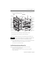
1
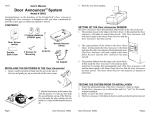
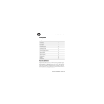
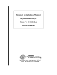
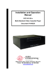
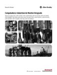
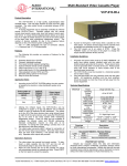
Installation Instructions
Hard Disk Drive Upgrade Kit
Catalog Number 6189V-25HDDKIT
For
Page
Important User Information
2
Safety Precautions
3
Parts List
4
Required Tools
4
Replace the Hard Disk Drive
4
Back Up the Hard Disk Drive
4
Remove the Hard Disk Drive
5
Install the New Hard Disk Drive
8
Install New Operating System and Restore Data
9
Additional Resources
10
About This Publication
This document shows how to replace the hard disk drive (HDD) in the 12 in.,
15 in., and 17 in. models of the 6181P VersaView Integrated Display Computers.
HDD Upgrade Kit
Computer Compatibility
Series
Revision
6189V-25HDDKIT
6181P-12XXXX
A
All
6181P-12XXXX
B
All
6181P-12XXXX
C
A
6181P-15XXXX
A
All
6181P-15XXXX
B
All
6181P-15XXXX
C
A
6181P-17XXXX
A
All
6181P-17XXXX
B
All
6181P-17XXXX
C
A
Publication 6181P-IN007C-EN-P - May 2006
2
Hard Disk Drive Upgrade Kit
Important User Information
Solid state equipment has operational characteristics differing from those of electromechanical equipment.
Safety Guidelines for the Application, Installation and Maintenance of Solid State Controls (Publication
SGI-1.1 available from your local Rockwell Automation sales office or online at
http://www.literature.rockwellautomation.com) describes some important differences between solid state
equipment and hard-wired electromechanical devices. Because of this difference, and also because of the
wide variety of uses for solid state equipment, all persons responsible for applying this equipment must
satisfy themselves that each intended application of this equipment is acceptable.
In no event will Rockwell Automation, Inc. be responsible or liable for indirect or consequential damages
resulting from the use or application of this equipment.
The examples and diagrams in this manual are included solely for illustrative purposes. Because of the many
variables and requirements associated with any particular installation, Rockwell Automation, Inc. cannot
assume responsibility or liability for actual use based on the examples and diagrams.
No patent liability is assumed by Rockwell Automation, Inc. with respect to use of information, circuits,
equipment, or software described in this manual.
Reproduction of the contents of this manual, in whole or in part, without written permission of Rockwell
Automation, Inc., is prohibited.
Throughout this manual, when necessary, we use notes to make you aware of safety considerations.
WARNING
IMPORTANT
ATTENTION
Identifies information about practices or circumstances that can cause an explosion in
a hazardous environment, which may lead to personal injury or death, property
damage, or economic loss.
Identifies information that is critical for successful application and understanding of
the product.
Identifies information about practices or circumstances that can lead to personal injury
or death, property damage, or economic loss. Attentions help you to identify a hazard,
avoid a hazard, and recognize the consequences.
SHOCK HAZARD
Labels may be located on or inside the equipment, for example, a drive or motor, to
alert people that dangerous voltage may be present.
BURN HAZARD
Labels may be located on or inside the equipment, for example, a drive or motor, to
alert people that surfaces may be dangerous temperatures.
Publication 6181P-IN007C-EN-P - May 2006
Hard Disk Drive Upgrade Kit
3
Safety Precautions
Observe the following precautions when working with the computer’s hard disk
drive.
•
•
•
•
Do not touch internal components unnecessarily.
Always handle the drive by its metal frame.
Store the drive in an anti-static bag when it is not installed.
Never disconnect or install a drive with the power turned on.
SHOCK HAZARD
Failure to follow proper safety procedures could result in severe electrical
shock or damage to the computers.
ATTENTION
ATTENTION
ATTENTION
Disconnect all power from the computer before removing and installing
components. Failure to disconnect power could result in severe electrical shock
or damage to the computer.
Electrostatic discharge (ESD) can damage the computer and components. Make
sure you work in a static-safe environment and wear a grounding strap
whenever handling circuit boards, memory, or other internal components.
Mechanical shock can damage hard disk drives (HDD). Do not drop or bump the
drive. Do not push on top cover of HDD. Do not touch printed circuit board
without ESD protection. See HDD label for additional care and handling
instructions.
Publication 6181P-IN007C-EN-P - May 2006
4
Hard Disk Drive Upgrade Kit
Parts List
The hard disk drive upgrade kit consists of these items.
• Hard disk drive (HDD)
• Connector-stabilization plate preassembled with dielectric film and
industrial doublestick tape
• L-shaped shock-stabilization shim
• Four flat-head M3 screws with thread lock
• Four pan-head M3 screws with lock washers
• Upgrade identification label
Required Tools
Use a Phillips #2 screwdriver for installation.
TIP
For easiest installation, use a screwdriver with magnetic tip.
Replace the Hard Disk Drive
This section shows how to replace the existing hard disk drive (HDD) in the
computer. It contains procedures to:
•
•
•
•
back up HDD data.
remove the HDD.
install the HDD.
install new operating system (OS) and restore backup data.
Back Up the Hard Disk Drive
Because you will replace the hard disk drive (HDD), you will need to install the
operating system (OS) on your new drive. For a default OS installation, use the
rebuild CD that shipped with your VersaView computer. This will not include
programs and data that have been added to the system.
IMPORTANT
Program data must be backed up independently before you remove the old
HDD. After installing the new HDD and OS, restore your backup data and
reinstall any application programs you previously had on the old HDD.
Publication 6181P-IN007C-EN-P - May 2006
Hard Disk Drive Upgrade Kit
5
Remove the Hard Disk Drive
Follow these steps to remove the hard disk drive (HDD).
1. Disconnect power from the computer.
2. Remove the screws securing the back cover.
1200P
1500P
IMPORTANT
Note the location and orientation of all cables before you remove the existing
hard drive and cabling, so that you can reattach them correctly.
3. Remove the four screws that fasten the HDD assembly to the chassis.
4. Lift the HDD assembly out of the chassis.
5. Open the HDD brackets.
TIP
HDD brackets will vary in shape depending on the computer model, series,
and revision.
Publication 6181P-IN007C-EN-P - May 2006
6
Hard Disk Drive Upgrade Kit
6. Disconnect the IDE adapter/cable (40…44 pin) from the HDD.
HDD
IDE adapter
IDE cable
TIP
It is not necessary to separate the IDE adapter from the IDE cable. Some
VersaView computers secured these parts with hot-melt glue. This glue can be
softened with isopropyl alcohol.
Series A VersaView computers do not use an adapter. The IDE cable connects
directly to the HDD.
7. Lift the HDD out of the bracket.
1200P
HDD Bracket
Shim
HDD
Connector-stabilization Plate
Rubber Shock-mount Strips
HDD Bracket
Series C, Revision A shown.
Your computer may vary.
Publication 6181P-IN007C-EN-P - May 2006
Hard Disk Drive Upgrade Kit
1500P
7
HDD Bracket
Shim
Rubber Shock-mount Strips
Connector-stabilization Plate
HDD
HDD Bracket
Series C, Revision A shown.
Your computer may vary.
1700P
HDD Bracket
HDD
Rubber Shock-mount
Strips
Connector-stabilization Plate
Shim
HDD Bracket
Series C, Revision A shown.
Your computer may vary.
Publication 6181P-IN007C-EN-P - May 2006
8
Hard Disk Drive Upgrade Kit
Install the New Hard Disk Drive
ATTENTION
Electrostatic discharge (ESD) can damage the computer and components. Make
sure you work in a static-safe environment and wear a grounding strap
whenever handling circuit boards, memory, or other internal components.
Follow these steps to install the hard disk drive (HDD).
1. Attach the HDD to the connector-stabilization plate using four M3 flat-head
screws.
TIP
Dielectric layers face the HDD and screws are flush. The HDD label faces the
back cover in all VersaView panel-mount computers.
2. Replace the old shim with the new L-shaped shim and place into bracket A.
Old shim
L-shaped shim
3. Place rubber shock-mount strip A into bracket A.
4. Place the HDD within rubber shock-mount strip A, sliding the
connector-stabilization plate through the opening of bracket A.
TIP
Use the shim with gray shock-mount strips. If you have black shock-mount
strips you may omit the shim or replace the strips with catalog number
6189V-25HDDSA.
5. Remove the protective paper from the doublestick tape on the
connector-stabilization plate.
6. Connect the IDE adapter/cable to the HDD, aligning pin 1 of the HDD with
the red stripe on the cable.
WARNING
Be careful to install the connector in the proper orientation. The connector is
keyed to help this process. Make sure that the connector is not shifted by row
or column from its correct position.
Publication 6181P-IN007C-EN-P - May 2006
Hard Disk Drive Upgrade Kit
9
7. Press the IDE adapter/cable firmly against the connector stabilization plate
to adhere to the doublestick tape.
1200P, 1500P
1700P
HDD Bracket B
Top
HDD Bracket A
Rubber
Shock-mount
Strip B
L-shaped Shim
Rubber
Shock-mount
Strip A
HDD
Doublestick tape
HDD
Connectorstabilization
Plate
Connectorstabilization
Plate
Doublestick tape
Rubber
Shock-mount
Strip A
Rubber
Shock-mount
Strip B
L-shaped Shim
HDD Bracket B
HDD Bracket A
8. Place rubber shock-mount strip B around the HDD as shown.
9. Place HDD bracket B onto rubber shock-mount strip B.
10. Attach the HDD assembly to the chassis using four M3 pan-head screws.
TIP
Series A VersaView computers do not use an adapter. The IDE cable connects
directly to the HDD. The cable itself should be adhered to the tape.
11. Affix the HDD upgrade label to the back cover of the unit with the left edge
aligned with the left edge of the nameplate, for easy reference.
Be sure not to cover any other labels.
Install New Operating System and Restore Data
With the new hard disk drive (HDD) installed, you are now ready to:
• reinstall the operating system (OS).
• install any application programs previously stored on the old HDD.
• restore backup data.
Publication 6181P-IN007C-EN-P - May 2006
10
Hard Disk Drive Upgrade Kit
Additional Resources
For additional information on the VersaView computers, refer to VersaView
Integrated Display Computers User Manual, publication 6181P-UM001.
You can view or download publications at:
http://www.literature.rockwellautomation.com
Allen-Bradley and VersaView are registered trademarks of Rockwell Automation, Inc.
Trademarks not belonging to Rockwell Automation are property of their respective companies.
Publication 6181P-IN007C-EN-P - May 2006
Hard Disk Drive Upgrade Kit
11
Publication 6181P-IN007C-EN-P - May 2006
Rockwell Automation Support
Rockwell Automation provides technical information on the web to assist you in
using its products. At http://support.rockwellautomation.com, you can find
technical manuals, a knowledge base of FAQs, technical and application notes,
sample code and links to software service packs, and a MySupport feature that you
can customize to make the best use of these tools.
For an additional level of technical phone support for installation, configuration and
troubleshooting, we offer TechConnect Support programs. For more information,
contact your local distributor or Rockwell Automation representative, or visit
http://support.rockwellautomation.com.
Installation Assistance
If you experience a problem with a hardware module within the first 24 hours of
installation, please review the information that's contained in this manual. You can
also contact a special Customer Support number for initial help in getting your
module up and running:
United States
1.440.646.3223
Monday – Friday, 8am – 5pm EST
Outside United
States
Please contact your local Rockwell Automation representative for any
technical support issues.
New Product Satisfaction Return
Rockwell tests all of its products to ensure that they are fully operational when
shipped from the manufacturing facility. However, if your product is not
functioning and needs to be returned:
United States
Contact your distributor. You must provide a Customer Support case number
(see phone number above to obtain one) to your distributor in order to
complete the return process.
Outside United
States
Please contact your local Rockwell Automation representative for return
procedure.
ö
Publication 6181P-IN007C-EN-P - May 2006
Supersedes Publication 6181P-IN007B-EN-P - February 2006
PN 41061-373-01(3)
Copyright © 2006 Rockwell Automation, Inc. All rights reserved. Printed in the U.S.A.