Transcript
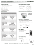
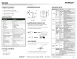
CM37 HIGH RESOLUTION DISCRETE CEILING MOUNT CAMERA PRODUCT FEATURES •600 Lines of Resolution •Auto White Balance •Auto Back Light Compensation •Auto Electronic Shutter •Built-in 3.7mm Pinhole Lens •Discreet Ceiling Mount Design •12 Volt DC Power Required •For Indoor Use CAMERA DIMENSIONS / LINE ART 2.4” 2.0” 4.7” 4.7” CAMERA INSTALLATION/CONNECTIONS SPECIFICATIONS Model No. CM37 Image Sensor 1/3” Sharp High Resolution CCD TV System NTSC Effective Pixels 768 (H) x 494 (V) Lens 3.7mm Fixed Focal Length (Pinhole Style) Maximum Aperture Ratio F1.2 Scanning System 2:1 Interlaced Sync System Internal Video Output 1.0Vp-p 75ohm Composite Resolution 600 TV Lines Minimum Illumination 0.6 Lux S/N Ratio More than 48dB Gamma Characteristic 0.45 Electronic Shutter Speed 1/60 ~ 1/100,000 Second BLC (Backlight Compensation) On (Factory Default) AGC (Automatic Gain Control) On (Factory Default) AWB (Automatic White Balance) On (Factory Default) AES (Automatic Electronic Shutter) On (Factory Default) Power Requirement 12 Volts DC (Regulated) 4) While holding the unit in position, re-check the camera’s Power Consumption 75mA Operating Temperature 14°F ~ 122°F Weight 7.8oz. 5) If necessary adjust the vertical view angle, do the following Housing Polycarbonate (Off White) Weatherproof Rating Indoor Only Dimensions (L x W x H) 4.7” x 2.4” * All specifications subject to change without notice for quality improvement PACKAGE CONTENTS 1) Select a location in the ceiling where you want to install the camera unit. 2) Insert power lead into power connector (insure proper voltage is supplied and observe polarity). Insert video lead into BNC connector (push, then twist to lock BNC connector in place). 3) With your hand, position the camera unit so the camera is aimed toward the area to be observed. horizontal sighting to ensure correct position. - loosen screw with a screwdriver. Turn the camera board to the desired angle (you may use a portable monitor or make communication with the master control room to make sure that the viewing angle is correct). Tighten screw to secure the vertical viewing angle. 6) To secure the unit in the location selected, tighten the screws in the holes as shown below. (1) Camera (1) Mounting Hardware Packet (1) User Manual ♦ 3625 Cincinnati Avenue, Rocklin, CA 95765 ♦ 888-874-3336 ♦ www.northernvideo.com Rev. 120613