1
DAEnetIP2 User Manual
18 Nov 2013
DAEnetIP2
User Manual
Date: 18 Nov 2013
Describes the features of DAEnetIP2 with firmware version 4.097
-1-
DAEnetIP2 User Manual
18 Nov 2013
Content
1. Features ............................................................................................................3
2. Technical parameters........................................................................................4
3. Application examples.......................................................................................5
4. Default Settings................................................................................................7
5. Connectors and ports........................................................................................9
6. Web access.....................................................................................................11
7. SNMP access..................................................................................................22
8. Appendix 1. Power supply.............................................................................29
9. Appendix 2. DAEnetIP2 installation..............................................................30
10. Appendix 3. Install and power on DAEnetIP2 + denkovi relay board (kit).32
11. Appendix 4. Port forwarding - for advanced users.......................................39
12. Appendix 5. Software...................................................................................40
13. Appendix 6. Software examples...................................................................46
14. Appendix 7. HTTP API commands..............................................................47
15. Appendix 8. Firmware upgrade....................................................................48
16. Appendix 9. Digital I/O ports (P3/P5)..........................................................50
17. Appendix 10. Using analog inputs port (P6)................................................51
18. Appendix 11. Using analog temperature sensors.........................................52
19. Appendix 12. Mechanical drawing...............................................................55
20. Document revisions......................................................................................56
-2-
DAEnetIP2 User Manual
18 Nov 2013
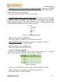
1. Features
DAEnetIP2 is multifunctional Ethernet device (IP controller) for management and
control. It could be used for industrial and home automation, access control, fire and
security systems or embedding in other systems. It is suitable also for controlling
relay boards and tracking different sensors via internet.
•
10 Mb Ethernet interface with Link/Activity Led
• Power supply 7.5 - 25VDC
• Low power consuption (<50mA/12V)
•
•
•
•
•
•
•
•
•
•
•
•
•
•
8 analog inputs with 10 bit resolution (0-3.3VDC) (no pull-up or pull-down
resistors)
16 (2x8) bit configurable digital I/O port (0-3.3VDC)
Standart protocols: ARP, IP, ICMP (ping), DHCP
Supports snmp v1 (snmpset, snmpget, snmptrap), HTTP (web server with
autorization) , TFTP (for firmware upgrade)
Ports for SNMP (161) and HTTP (80) can be changed
Two MAC addresses protection
It can be configured with SNMP requests or web browser
Integrated WEB server for all functions/parameters access. I/O lines labels
can be changed via browser.
Reset of the digital outputs on incoming/outgoing ping timeout
Function "load outputs states from EEPROM on boot"
Each I/O line can be named by user via web browser
It can send traps according analog ADC level
One analog inputs may be referred to control one digital output according its
input level
Working temperature range: 0ºC to 70ºC
-3-
DAEnetIP2 User Manual
18 Nov 2013
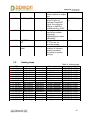
2. Technical parameters
Parameter
Size
Power supply voltage
CPU power supply (output level 3.3VDC)
Digital I/O count
Analog inputs count
1)
Digital inputs count
Default settings jumper
LED (Link, Activity,
Power On)
Save I/O states
DHCP
Network parameters
MAC lock (protection)
SNMPv1
Read-Write Community String
Read-Only Community String
SNMP traps
SNMP I/O access commands
Web server for configuration/access
TFTP client for remote firmware update
Command for TFTP update
(Web,SNMP)
Enable/Disable TFTP update
Table 1. Technical parameters
Value
43x55mm
7.5 - 25VDC
3.3V
2x8
8 (10bit ADC, Vref=3.3V)
8
Yes
Yes
Yes
Yes
IP/Mask/Default gateway
Yes
Yes (snmpget,snmpset)
Yes
Yes
Yes
Yes
Yes
Yes
Yes
Yes
1) These digital inputs are the analog inputs, but the input voltage is software converted to 1 or 0
-4-
DAEnetIP2 User Manual
18 Nov 2013
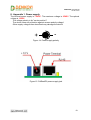
3. Application examples
3.1.
Remote control
DAEnetIP2
PC
Relay Board
Power supply
Electrical device
Figure 1. Example 1
Data acquisition
DAEnetIP 2
MP
SN
SNMP
DAEnetIP 2
Sensor
Sensor
DAEnetIP 2
SN
MP
SN
MP
Tr
ap
Sensor
SNMP Monitoring
Software
SNMP Trap
SNMP
HTTP
Web browser
H
TT
P
3.2.
Figure 2. Example 2
-5-
DAEnetIP2 User Manual
18 Nov 2013
3.3.
Watchdog function
Figure 3. Example 3
-6-
DAEnetIP2 User Manual
18 Nov 2013
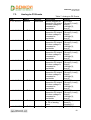
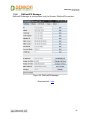
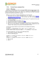
4. Default Settings
4.1.
Table with default settings
These are the default (factory) settings of DAEnetIP2. When you buy the module you
will receive it with these settings. If not, you can load the default settings (see point
4.2).
Parameter
(according Web pages)
DHCP
IP
Mask
Gateway
VLAN ID
VLAN mode
Access MAC 1,2
SNMP access to IP
SNMP listen UDP port
SNMP Read-only community string
SNMP RW community string
SNMP/Web Access network IP
SNMP/Web Access network Mask
Ping Timeout
Restart on incoming ping timeout
Restart on remote IP timeout
Remote monitor IP
I/O ports settings
Pull-Up/Pull-Down
Pull-up/down for inputs
Reset I/O ports on restart
Digital filter for ADC
TFTP update
TFTP Server IP
Broadcast Frames
Web Server
Web Server TCP port
SNMP traps target host
SNMP traps community
Low/High Analog Trap Threshold
Analog Events – Low, High, Acc
Web user/password
Table 2. Default settings
Value
Disabled
172.16.100.2
255.255.255.0
172.16.100.1
1
Disabled
000000000000
Enabled
161
000000000000
private
172.16.100.1
0.0.0.0 (disabled)
6
Disabled
Disabled
172.16.100.1
P3,P5 - Outputs
All “pull-down”
Enabled
Disabled
Enabled
Enabled
172.16.100.1
Parse
Enabled
80
172.16.100.1
public
0/1023 (disabled)
None
admin/admin
-7-
DAEnetIP2 User Manual
18 Nov 2013
4.2.
Steps for loading default settings
In case the access of the module is lost, factory (default settings) may be applied and
the module parameters will be returned back as those in point 4.1 from the current
document.
Figure 4. Loading default settings
1.
2.
3.
4.
5.
6.
Turn off the power supply of the device
Move the jumper from position 1 to position 2
Turn on the power supply of the device
Move the jumper from position 2 to position 1
Turn off the power supply of the device
Turn on the power supply of the device
-8-
DAEnetIP2 User Manual
18 Nov 2013
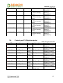
5. Connectors and ports
5.1.
DAEnetIP2 ports
Figure 5. DAEnetIP2 ports
-9-
DAEnetIP2 User Manual
18 Nov 2013
5.2.
DAEnetIP2 ports description
Table 3. I/O Ports
Pin N
1
2
3
4
5
6
7
8
9
10
Port JP3 (P3)
digital outputs
Bit
Func
Dir
1
Free
I/O
2
Free
I/O
3
Free
I/O
4
Free
I/O
5
Free
I/O
6
Free
I/O
7
Free
I/O
8
Free
I/O
GND
PWR
GND
PWR
Port JP4 (P5)
digital outputs
Bit
Func
Dir
1
Free
I/O
2
Free
I/O
3
Free
I/O
4
Free
I/O
5
Free
I/O
6
Free
I/O
7
Free
I/O
8
Free
I/O
+3.3V
PWR
GND
PWR
Port JP5 (P6)
(digital/analog inputs)
Bit
Func
Dir
1
Free
Ain
2
Free
Ain
3
Free
Ain
4
Free
Ain
5
Free
Ain
6
Free
Ain
7
Free
Ain
8
Free
Ain
+3.3V(Vref)
PWR
GND
PWR
Table 4. System port
Pin N
1
2
3
4
5
6
7
8
9
10
Bit
-
DAEnetIP2 System Port JP6 (reserved, not used)
FUNC
+3.3V
+3.3V
Reserved
Ping Led
Reserved
Target RST
Reserved
Reserved
Reserved
GND
Dir
PWR
PWR
Out
Out
PWR
Legend:
•
•
•
•
•
•
“Free” – the pin is free to be used by user.
“XXXXXX” - the pin is reserved for special function – can not be accessed.
“In” – the pin is digital input
“Out” – the pin is digital output
"I/O" – the pin is digital input or output depending the settings
“Ain” – analog input
-10-
DAEnetIP2 User Manual
18 Nov 2013
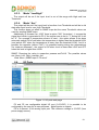
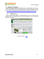
6. Web access
Figure 6. Web access
It is possible to configure DAEnetIP2 via IE, Chrome, Mozilla or other browser.
The browser must support JavaScript. There is username and password (Basic
Authentication). The web server has only one session – only one user can access
the DAEnetIP2 via web at a time. The session has timeout 60 seconds if there is not
access from the browser. After that another user can access the module. This is
done because of security reasons.
-11-
DAEnetIP2 User Manual
18 Nov 2013
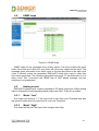
6.1.
Setup page
Figure 7. Setup page
6.1.1.
Firmware version
This is the current firmware version. Can not be changed
6.1.2.
MAC address
The MAC address of the module. Can not be changed
6.1.3.
IP address
The IP address of the module.
6.1.4.
Subnet Mask
The subnet mask of the module.
6.1.5.
Default Gateway
The Default gateway of the module.
SNMP: cfgIP.0, cfgNetMask.0, cfgDefGW.0
Web: Menu „Setup->IP address”, „Setup->Subnet Mask”, „Setup->Default
Gateway”
-12-
DAEnetIP2 User Manual
18 Nov 2013
NOTE! The static parameters are stored in the EEPROM of the device. They are not changed by
DHCP server. When accessing Web and enabled DHCP mode, the IP, Mask and Gateway are those
fetched by the DHCP server and not the static.
6.1.6.
VLAN
DAEnetIP2 can work with normal or tagged packets (IEE 802.11q). It supports the
whole set of 12bit VLAN tags.
SNMP: Chagne the bit cfgMode.0 and setting the VLAN
tag in cfgVLANTag.0
Web: Menu „Setup->Tagged VLAN mode” and „Setup->VLAN ID”
6.1.7.
DHCP
The IP,MASK and Gateway can be brought by DHCP server.
SNMP: Change its bit in cfgNewMode.0
Web: Menu „Setup-> DHCP client”
IMPORTNAT! Allowing DHCP client when there is not available DHCP server (or network issue)
may make DAEnetIP2 module not to load the network settings and in this way the access may be lost.
To avoid this DAEnetIP2 module waits about 40 sec to receive its network settings. In case of failure,
DAEnetIP2 module loads the last saved static parameters and begins to work with them and
meanwhile continues searching the DHCP server. If there is answer from the DHCP server, the
DAEnetIP2 accepts immediately the new settings and reconfigures its network interface.
6.1.8.
MAC filtering
DAEnetIP2 has MAC protection. This means that if it is enabled it can be
accessed from one/two MAC addresses. For disable the MAC protection, the MAC
must be 000000000000.
SNMP: cfgMACLock1.0, cfgMACLock2.0
Web: Menu „Setup-> Access MAC address 1” and „Setup-> Access MAC address
NOTE! When using MAC filtering please note that while accessing from external networks to the
DAEnetIP2 module arrive packets with MAC address of the Default Gateway. In this way it must be
always one of the both protected MAC addresses.
6.1.9.
SNMP/Web Access network
This function allows to define only one network which have to access the
DAEnetIP2 module via SNMP or Web. The function is for access filtering and
protection not only MAC addresses level, but and for IP addresses level.
The filtering is only for SNMP and WEB access. All the rest protocols ARP, ICMP,
DHCP are not filtered.
NOTE! MAC protection is with higher priority than SNMP/Web access protection.
6.1.10. SNMP settings
This section is for enable/disable SNMP access and SNMP community strings. It
is also possible to change the SNMP port from this page.
-13-
DAEnetIP2 User Manual
18 Nov 2013
SNMP: Change of cfgSNMPport.0
Web: Menu „Setup->SNMP settings/Listen on UDP port ”
SNMP: Change its bit in cfgMode.0
Web: Menu „Setup-> SNMP access to IP configuration”
SNMP: cfgPassword.0 and cfgReadOnlyPassword.0
Web: Menu „Setup-> SNMP read-write community string” and „Setup-> SNMP
readonly community string”
NOTE! The SNMP password for read/write can not be accessed via SNMP.
6.1.11. ICMP monitoring modes
The DAEnetIP2 module supports two way (incoming/outgoing) mode for
monitoring via receiving/sending ICMP Echo Request and ICMP Echo Reply packets.
With this function the DAEnetIP2 module can be used as a device for active
monitoring of networks and networks devices. The DAEnetIP2 module performs and
restart pulse if there is not answer. The common parameter "Timeout" (in minutes)
must be given to determine the timeframe when the request/answer must be
received. If the timeout elapses then the i/o ports are reset.
Incoming ICMP monitoring When the incoming ICMP monitoring mode is
enabled, the DAEnetIP2 module expects ping in the given timeout.
IMPORTANT! If there is very big traffic in the network it is absolutely possible the incoming ping to
be not received. That's why it must be sent 5-10 ping requests.
Outgoing ICMP monitoring During outgoing monitoring the DAEnetIP2 module
generates ping to the given IP address and expects answer within the given
timeframe. The request generating is performed several times in minute.
The both ICMP modes use one shared parameter "timeout" however they have
separate timers.
Restart Target Device To restart external device (via relay driver) during
monitoring mode it is used special pin "Target RST" (look at the i/o port table). In this
way it is possible restarting of different electrical appliances (120/220VAC including).
From firmware version 4.097 it is possible to copy that signal to DAEnetIP2 - P5. The
restart of external devices may be started/stopped by the user. The restart pulse with
may be set by the user: (from 0 up to 32767 )x250ms.
The restart may be done manually via the following commands:
SNMP: Changing bit cfgMode.0; cfgResetPulse.0, pctrlRestart.0
(read-only), cfgP5DupRST.0
Web: Menu „Setup->Restart external device”, „Setup->External device restart pulse
width”, „I/O ports -> Force TargetRST”, „Setup->Duplicate 'TargetRST' on P5 pins ”
IMPORTANT! The setting of pulse width greater than “Ping Timeout” will make the non-definition
(possible infinity) increasing of the restart pulse when there is not ping request or answer within the
given timeout. The reason is in the cyclic start of the pulse most frequently than it's width!
-14-
DAEnetIP2 User Manual
18 Nov 2013
Setting low level the I/O lines while monitoring restart If this option is enabled
DAEnetIP2 will set in logical "0" all the outputs P3 and P5 (look figure 5 and table 3)
SNMP: Change its bit in cfgNewMode.0
Web: Menu „Setup-> Reset I/O ports on ping restart”
Incoming Ping request indicator "Ping LED" Activating this mode will allow
DAEnetIP2 module to become in simple network analyzer (with set network
parameters), which can indicate "ping" requests to its IP address. Each received
request performs change of output "Ping LED" (see the i/o table description). The
schematic bellow shows how to connect this pin to LED.
Figure 8. Connecting Ping LED
SNMP: Change its bit in cfgNewMode.0
Web: Menu „Setup-> Toggle JP6.4 on outgoing ping request”
Second LED indicator. This indicator may show: „Power ON”, “Ping IN”,
“Ping OUT”, “Ping BOTH”, “DHCP valid IP”.
SNMP: Change its bit in cfgLED2mode.0
Web: Menu „Setup-> Second LED mode”
6.1.12. IO Ports settings
DAEnetIP2 has 8+8 digital I/O (P3/P5) and 8 analog inputs (P6). The analog
inputs may be used also for digital inputs (software conversion)
Figure 9. I/O ports
When Input is selected, that means this pin is input, otherwise it is output.
SNMP: Change its bit in cfgP3Dir.0, cfgP5Dir.0 (1=Out,2=In)
Web: Menu „Setup-> I/O ports settings”
-15-
DAEnetIP2 User Manual
18 Nov 2013
When Pull-up is selected, that means there is pull-up resistor of about 50kOhm.
When the pin is selected to work as output these pull-up/down resistors are not
connected.
From this section also it is possible to:
o enable/disable save outputs at reboot. By default the output states are set
to 0. However if this option is set, the output states will be loaded from the
EEPROM (where they are recorded the states of the last change before
reboot). As each EEPROM has limited read/write cycles, it is not
recommend to enable this option when high rate of changing is available.
SNMP: Change its bit in cfgNewMode.0
Web: Menu „Setup-> Save I/O ports’ states”
o pull-up/down for inputs (global enable/disable)
SNMP: Global stop/start of the mode: change its bit cfgMode.0 (NO_PULLUP/DOWN _BIT3)
The individual direction of each input: Change its bit in cfgP3Pull.0 and
cfgP5Pull.0 ( 1=Pull-down, 0=Pull-up.)
Web: Menu „Setup-> Pull-up/down for inputs” and table „I/O ports settings“
o digital filter for the ADC. When this option is activated, the analog inputs
returns the measured value slower, but more clear.
SNMP: Change bit (DISABLE_ANALOG_FILTER) in cfgMode.0
Web: Menu „Setup-> Digital filter for ADC ”
6.1.13. TFTP firmware update
DAEnetIP2 has TFTP client for firmware update. When the command is initiated,
the DAEnetIP2 module connects to the TFTP server and starts downloading the
firmware version. After checking if there is connection with the TFTP server and if the
file is correct the firmware will be updated and the module will be rebooted.
When there is not connection to the TFTP server, the module makes several
attempts before stop executing the command without firmware upgrade.
SNMP: Change its bit in cfgNewMode.0 to allow upgrade via TFTP;
cfgTFTPServerIP.0 and cfgUpdateFirmware.0 (read-only)
Web: Menu „Setup-> TFTP firmware update”, „Setup->TFTP server IP address”,
„Firmware Update”
IMPORTANT ! It is recommend the firmware upgrade not to be done in real environment. The
power supply failure during firmware upgrade will make DAEnetIP2 unusable.
IMPORTANT ! When it is done downgrade (it is loaded lower version of firmware), the default
settings must be loaded.
For detailed firmware upgrade information please see Appendix 5.
-16-
DAEnetIP2 User Manual
18 Nov 2013
6.1.14. Broadcast frames
In this mode DAEnetIP2 does not response of frames with MAC address FF-FFFF-FF-FF-FF. This allows DAEnetIP2 to hide from the world because it doesn’t
respond to ARP requests.
6.1.15. Web server
Enable/disable web access.
SNMP: Change its bit in cfgNewMode.0
Web: Menu „Setup-> Web server”
IMPORTANT! The WEB access may be allowed only after SNMP command (and of course after
loading the default settings). If however the SNMP access is disabled, then the allowing of the WEB
server may be done only after hardware loading of the default settings.
From this section the web port may be changed also. The port must be in range
from 1025 up to 65535. The attempt to assign port from 1-1024 will be accepted as
80. After setting this parameter, the DAEnetIP2 module will be restarted. After
changing this port, the url address must be something like this:
http://172.16.100.2:port
SNMP: Change cfgHTTPport.0
Web: Menu „Setup->Miscellaneous/ Web server ...on port ”
-17-
DAEnetIP2 User Manual
18 Nov 2013
6.2.
SNMP traps
Figure 10. SNMP traps
SNMP traps can be generated from Analog inputs if its level crosses the given
limits. If the limits are 0 and 1023 then there will not be any traps from this input. The
message gives information from which input is this trap and what is the input level
value. If several events are generated, DAEnetIP2 sends their traps in order they
have been generated. The controller generates traps each 2-3 seconds when it is in
alarm zone. This is because the SNMP trap is UDP based message and the
receiving is not guaranteed.
6.3.
Analog events
DAEnetIP2 Analog inputs could be attached to P5 digital output port. When analog
input is changed the corresponding digital output can react. There are 4 modes:
6.3.1.
Mode “Low”
The output will become “1” if the input level is less than Low Threshold and sets
the previous state when the input level is over Low Threshold.
6.3.2.
Mode “High”
The output will be set if the input level is higher than High.
-18-
DAEnetIP2 User Manual
18 Nov 2013
6.3.3.
Mode “Low/High”
The output will be set if the input level is out of the range with High and Low
Threshold.
6.3.4.
Mode “Acc”
The output will be set if the input level is less than Low Threshold and will be in old
state after input level is over High Threshold.
This function does not affect to SNMP traps but the same Threshold values are
used for sending SNMP traps.
Additionally in firmware ver. 4.097 there is option "INV" (Inversion) - it reverse the
signal level which is generated to P5 (if the regular was to set in "1" during INV it will
be "0". For example if temperature sensor is used - this option allows to be done
automatic switch ON of load when the temperature is higher than the threshold HIGH
(and switch OFF when the temperature is lower than the threshold LOW). And it is
possible the opposite (without "INV") it is possible heating during low temperatures
(for instance antennas) - the output is ON when level is lower than LOW and OFF
when the level is higher than HIGH.
SNMP: Changing the value in respective ромяна aevPinX.0. The possible values
are: None, Low, High, LowHigh, Acc
Web: Menu „SNMP traps-> P5 set at”
6.4.
I/O Ports
Figure 11. I/O ports web page
P3 and P5 are configurable digital I/O port (0-3.3VDC). It is possible to be
configured by the user for its own purposes - digital inputs or outputs.
P6 is 8 channel 10 bit analog input port. The reference voltage is 3.3VDC (from
power supply source)
-19-
DAEnetIP2 User Manual
18 Nov 2013
6.5.
Port Labels
Figure 12. Port Labels
From this web page it is possible to change the name for each I/O pin. Note this is
possible to be done only via web and not via snmp.
-20-
DAEnetIP2 User Manual
18 Nov 2013
6.6.
Account
Figure 13. Account settings
6.7.
Firmware Update
This command starts firmware update. The DAEnetIP2 will download the firmware
file from the TFTP server given in Setup section. After that the device will be
rebooted.
6.8.
Reboot
Reboots DAEnetIP2.
-21-
DAEnetIP2 User Manual
18 Nov 2013
7. SNMP access
DAEnetIP2 supports SNMPv1 protocol – snmpget and snmpset. It may be
configured/read all the parameters via these commands. Read-only community string
is used for reading and Read-Write Community String is used for changing the
parameters. Note that it is not possible using of snmpwalk. Parameters that can be
changed, are grouped according to their functions in the tables below. To obtain a
valid OID number it is necessary to replace the “x” symbol with the prefix
”.1.3.6.1.4.1.19865”. Also all the snmp commands are described in the MIB file. All
the functions can be accessed via SNMP and WEB
IMPORTANT! During SNMP access, it must be used snmpget and snmpset only to one OID and not
to group of OIDs. Other commands (snmpwalk for instance) are not supported.
NOTE! Because of the specific of the SNMP protocol supported by DAEnetIP2 (it is not possible to
access several OIDs), the initial setting of IP/MASK/Gateway must be done via Web. Otherwise the
DAEnetIP2 module may become not reachable, because of the limitation of only one OID accessing
per a time via snmp.
7.1.
Configuration settings
OID
x.1.1.1.0
Name
cfgIP
Access
read-write
x.1.1.2.0
cfgMAC
read-only
x.1.1.3.0
cfgVLANTag
read-write
x.1.1.4.0
cfgPassword
read-write
x.1.1.5.0
cfgMACLock1
read-write
x.1.1.6.0
cfgMACLock2
read-write
x.1.1.7.0
cfgPingTime
read-write
x.1.1.8.0
cfgVersion
read-only
x.1.1.9.0
cfgMode
read-write
Table 5. Configuration settings
Description
Syntax
IP Address of
IpAddress
DAEnetIP2 module
MAC address of
PhysAddress
DAEnetIP2 module
VLAN ID (12bit) in
INTEGER(0..40
VLANEnabled mode
95)
Read-Write community
OCTET
string (password)
STRING (SIZE
(4..12))
MAC address of first
PhysAddress
remote machine allowed
to access DAEnetIP2
module
MAC address of second PhysAddress
remote machine allowed
to access DAEnetIP2
module
The time (in minutes)
INTEGER(0..25
since last ping request
5)
to reboot system and
target
Firmware version,
INTEGER(0..65
LSB=VER_MINOR,
535)
MSB=VER_MAJOR
Contains different bit
INTEGER(0..25
flags for DAEnetIP2
5)
-22-
DAEnetIP2 User Manual
18 Nov 2013
operating modes:
ENABLED_BIT – bit0,
BROADCAST_DISABL
E-bit1,
VLAN_TAG_ENABLEbit2,
NO_LARGE_PACKETS
-bit3,
PINGRESTART_ENAB
LE-bit4,
SWITCH_CONTROLbit5,
SECONDARY_TARGE
T-bit6,
USE_ANALOG_PINSbit7
(Disable_Analog_Filter
for ver >4.094)
x.1.1.10.0
cfgReset
read-only
x.1.1.11.0
cfgNewMode
read-write
x.1.1.12.0
cfgResetPulse
read-write
x.1.1.13.0
cfgResetCount
read-write
x.1.1.14.0
cfgDefGW
read-write
Read of this OID causes NULL
rest of DAEnetIP2
module
Contains different bit
INTEGER(0..25
flags for DAEnetIP2
5)
operating modes:
SAVE_IOPORTS – bit0,
PING_LED – bit1,
PING_TIMEOUT_IORE
SET – bit2,
TFTP_UPDATE – bit3,
DHCP_CLIENT – bit4.
MONITOR_TIMEOUT_
RESTART – bit5,
WEB_SERVER – bit6,
SWITCH_RESTART –
bit7
(fw>=4.066) Defines the
time ot the RST pulse:
value * 250ms
(fw>=4.066) Number
of consecutive resets to
perform
when
ping
timeout is active. Value
255 disables counting.
Actual count is this
value + 1
IP Address of Default
INTEGER(0..32
767)
INTEGER(0..25
5)
IpAddress
-23-
DAEnetIP2 User Manual
18 Nov 2013
x.1.1.15.0
cfgNetMask
read-write
x.1.1.16.0
cfgMonitorIP
read-write
x.1.1.17.0
cfgReadOnlyP
assword
read-write
x.1.1.18.0
cfgTrapServerI
P
cfgTrapPassw
ord
read-write
x.1.1.20.0
cfgAccessIP
read-write
x.1.1.21.0
cfgAccessMas
k
read-write
x.1.1.22.0
cfgHTTPport
read-write
x.1.1.19.0
read-write
x.1.1.23.0
cfgSNMPport
read-write
x.1.1.24.0
cfgLED2mode
read-write
x.1.1.25.0
cfgP3Dir
read-write
x.1.1.26.0
cfgP5Dir
read-write
x.1.1.27.0
cfgP3Pull
read-write
x.1.1.28.0
cfgP5Pull
read-write
Gateway
IP Network Subnet
Mask
Remote IP address to
monitor via ICMP echo
requests
Read-only community
string (password)
Remote IP address of
TRAP manager
Community string for
trap messages
IP address of network
class allowed to access
DAEnetIP2
Mask of network class
allowed to access
DAEnetIP2
(fw>=4.094) Defines
listen port for Web
server. Allowed values
80 and >1024
(fw>=4.094) Defines
listen port for SNMP
server. Allowed values
161 and >1024
(fw>=4.094) Defines
LED2 behaviour
Bit mask with direction
of P3 pins. 1-Output, 0Input
Bit mask with direction
of P5 pins. 1-Output, 0Input
Bit mask with pullup/down mode P3 pins.
1-Pull-down, 0-Pull-up.
Doesn't reflect on output
pins
Bit mask with pullup/down mode P5 pins.
IpAddress
IpAddress
OCTET
STRING (SIZE
(4..12))
IpAddress
OCTET
STRING (SIZE
(4..12))
IpAddress
IpAddress
INTEGER(0..65
535)
INTEGER(0..65
535)
INTEGER
{ PowerOn(0),
PingIn(1),
PingOut(2),
PingBoth(3),
ValidIP(4) }
INTEGER(0..25
5)
INTEGER(0..25
5)
INTEGER(0..25
5)
INTEGER(0..25
5)
-24-
DAEnetIP2 User Manual
18 Nov 2013
x.1.1.29.0
cfgP5DupRST
read-write
x.1.1.30.0
cfgDefault
read-only
x.1.1.32.0
cfgTFTPServe
rIP
read-write
x.1.1.33.0
cfgUpdateFirm
ware
read-only
7.2.
1-Pull-down, 0-Pull-up.
Doesn't reflect on output
pins
Bit mask showing on
which P5 pins to
duplicate TargetRST
signal. Pins must be
outputs in cfgP5Dir.
Available from v.4.097
Reading this OID will
load factory default
settings of
DAEnetIP2and restart
DAEnetIP2.
Remote IP address of
TFTP server for
firmware update
Read of this OID causes
initiation of firmware
update procedure,
according to system
settings
INTEGER(0..25
5)
NULL
IpAddress
NULL
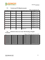
Analog traps
OID
x.1.1.122.1.0
x.1.1.122.2.0
x.1.1.122.3.0
x.1.1.122.4.0
x.1.1.122.5.0
x.1.1.122.6.0
x.1.1.122.7.0
x.1.1.122.8.0
x.1.1.122.9.0
x.1.1.122.10.0
x.1.1.122.11.0
x.1.1.122.12.0
x.1.1.122.13.0
x.1.1.122.14.0
x.1.1.122.15.0
x.1.1.122.16.0
Name
atrPin1Low
atrPin1High
atrPin2Low
atrPin2High
atrPin3Low
atrPin3High
atrPin4Low
atrPin4High
atrPin5Low
atrPin5High
atrPin6Low
atrPin6High
atrPin7Low
atrPin7High
atrPin8Low
atrPin8High
Access
read-write
read-write
read-write
read-write
read-write
read-write
read-write
read-write
read-write
read-write
read-write
read-write
read-write
read-write
read-write
read-write
Description
Pin low threshold
Pin high threshold
Pin low threshold
Pin high threshold
Pin low threshold
Pin high threshold
Pin low threshold
Pin high threshold
Pin low threshold
Pin high threshold
Pin low threshold
Pin high threshold
Pin low threshold
Pin high threshold
Pin low threshold
Pin high threshold
Table 6. Analog traps
Syntax
INTEGER(0..1023)
INTEGER(0..1023)
INTEGER(0..1023)
INTEGER(0..1023)
INTEGER(0..1023)
INTEGER(0..1023)
INTEGER(0..1023)
INTEGER(0..1023)
INTEGER(0..1023)
INTEGER(0..1023)
INTEGER(0..1023)
INTEGER(0..1023)
INTEGER(0..1023)
INTEGER(0..1023)
INTEGER(0..1023)
INTEGER(0..1023)
-25-
DAEnetIP2 User Manual
18 Nov 2013
7.3.
Anolog-to-P5 Events
OID
x.1.1.121.1.0
Name
aevPin1
Access
read-write
x.1.1.121.2.0
aevPin2
read-write
x.1.1.121.3.0
aevPin3
read-write
x.1.1.121.4.0
aevPin4
read-write
x.1.1.121.5.0
aevPin5
read-write
x.1.1.121.6.0
aevPin6
read-write
x.1.1.121.7.0
aevPin7
read-write
x.1.1.121.8.0
aevPin8
read-write
x.1.1.121.9.0
aevPin1Inv
read-write
x.1.1.121.10.0
aevPin2Inv
read-write
Table 7. Analog-to-P5 Events
Description
Syntax
Defines reaction on
INTEGER
respective P5 output { None(0), Low(1),
pin when voltage is
High(2),
compared to
LowHigh(3),
thresholds
Acc(4) }
Defines reaction on
INTEGER
respective P5 output { None(0), Low(1),
pin when voltage is
High(2),
compared to
LowHigh(3),
thresholds
Acc(4) }
Defines reaction on
INTEGER
respective P5 output { None(0), Low(1),
pin when voltage is
High(2),
compared to
LowHigh(3),
thresholds
Acc(4) }
Defines reaction on
INTEGER
respective P5 output { None(0), Low(1),
pin when voltage is
High(2),
compared to
LowHigh(3),
thresholds
Acc(4) }
Defines reaction on
INTEGER
respective P5 output { None(0), Low(1),
pin when voltage is
High(2),
compared to
LowHigh(3),
thresholds
Acc(4) }
Defines reaction on
INTEGER
respective P5 output { None(0), Low(1),
pin when voltage is
High(2),
compared to
LowHigh(3),
thresholds
Acc(4) }
Defines reaction on
INTEGER
respective P5 output { None(0), Low(1),
pin when voltage is
High(2),
compared to
LowHigh(3),
thresholds
Acc(4) }
Defines reaction on
INTEGER
respective P5 output { None(0), Low(1),
pin when voltage is
High(2),
compared to
LowHigh(3),
thresholds
Acc(4) }
Invert respective pin INTEGER {
for P5 on analog
None(0),
event
Inverted(1) }
Invert respective pin INTEGER {
-26-
DAEnetIP2 User Manual
18 Nov 2013
x.1.1.121.11.0
aevPin3Inv
read-write
x.1.1.121.12.0
aevPin4Inv
read-write
x.1.1.121.13.0
aevPin5Inv
read-write
x.1.1.121.14.0
aevPin6Inv
read-write
x.1.1.121.15.0
aevPin7Inv
read-write
x.1.1.121.16.0
aevPin8Inv
read-write
7.4.
for P5 on analog
event
Invert respective pin
for P5 on analog
event
Invert respective pin
for P5 on analog
event
Invert respective pin
for P5 on analog
event
Invert respective pin
for P5 on analog
event
Invert respective pin
for P5 on analog
event
Invert respective pin
for P5 on analog
event
None(0),
Inverted(1) }
INTEGER {
None(0),
Inverted(1) }
INTEGER {
None(0),
Inverted(1) }
INTEGER {
None(0),
Inverted(1) }
INTEGER {
None(0),
Inverted(1) }
INTEGER {
None(0),
Inverted(1) }
INTEGER {
None(0),
Inverted(1) }
Control port P3 (Digital outputs)
OID
x.1.2.1.1.0
Name
pctrlP3pin1
x.1.2.1.2.0
pctrlP3pin2
x.1.2.1.3.0
pctrlP3pin3
x.1.2.1.4.0
pctrlP3pin4
x.1.2.1.5.0
pctrlP3pin5
x.1.2.1.6.0
pctrlP3pin6
x.1.2.1.7.0
pctrlP3pin7
x.1.2.1.8.0
pctrlP3pin8
x.1.2.1.33.0
pctrlP3byte
Table 9. Control port P3
Access
Description
Syntax
readPort3 pin1 data
INTEGER
write
{ High(1), Low(0) }
readPort3 pin2 data
INTEGER
write
{ High(1), Low(0) }
readPort3 pin3 data
INTEGER
write
{ High(1), Low(0) }
readPort3 pin4 data
INTEGER
write
{ High(1), Low(0) }
readPort3 pin5 data
INTEGER
write
{ High(1), Low(0) }
readPort3 pin6 data
INTEGER
write
{ High(1), Low(0) }
readPort3 pin7 data
INTEGER
write
{ High(1), Low(0) }
readPort3 pin8 data
INTEGER
write
{ High(1), Low(0) }
readI/O port data as
INTEGER(0..255)
write
single byte
-27-
DAEnetIP2 User Manual
18 Nov 2013
7.5.
Control port P5 (Digital outputs)
OID
x.1.2.2.1.0
Name
pctrlP5pin1
Access
read-write
x.1.2.2.2.0
pctrlP5pin2
read-write
x.1.2.2.3.0
pctrlP5pin3
read-write
x.1.2.2.4.0
pctrlP5pin4
read-write
x.1.2.2.5.0
pctrlP5pin5
read-write
x.1.2.2.6.0
pctrlP5pin6
read-write
x.1.2.2.7.0
pctrlP5pin7
read-write
x.1.2.2.8.0
pctrlP5pin8
read-write
x.1.2.2.33.0 pctrlP5byte
read-write
Table 10. Control port P5
Description
Syntax
Port5 pin1 data
INTEGER
{ High(1), Low(0) }
Port5 pin2 data
INTEGER
{ High(1), Low(0) }
Port5 pin3 data
INTEGER
{ High(1), Low(0) }
Port5 pin4 data
INTEGER
{ High(1), Low(0) }
Port5 pin5 data
INTEGER
{ High(1), Low(0) }
Port5 pin6 data
INTEGER
{ High(1), Low(0) }
Port5 pin7 data
INTEGER
{ High(1), Low(0) }
Port5 pin8 data
INTEGER
{ High(1), Low(0) }
I/O port data as
INTEGER(0..255)
single byte
7.6.
Returned values are from 10bit Analog to Digital
Converter
OID
x.1.2.3.1.0
x.1.2.3.2.0
x.1.2.3.3.0
x.1.2.3.4.0
x.1.2.3.5.0
x.1.2.3.6.0
x.1.2.3.7.0
x.1.2.3.8.0
Name
pctrlP6pin1
pctrlP6pin2
pctrlP6pin3
pctrlP6pin4
pctrlP6pin5
pctrlP6pin6
pctrlP6pin7
pctrlP6pin8
Access
read-only
read-only
read-only
read-only
read-only
read-only
read-only
read-only
Table 11. Returned values from ADC
Description
Syntax
ADC Channel 1
INTEGER(0..1023)
ADC Channel 2
INTEGER(0..1023)
ADC Channel 3
INTEGER(0..1023)
ADC Channel 4
INTEGER(0..1023)
ADC Channel 5
INTEGER(0..1023)
ADC Channel 6
INTEGER(0..1023)
ADC Channel 7
INTEGER(0..1023)
ADC Channel 8
INTEGER(0..1023)
-28-
DAEnetIP2 User Manual
18 Nov 2013
8. Appendix 1. Power supply
The minimal power supply is 7.5VDC. The maximum voltage is 25VDC. The optimal
voltage is 12VDC
The voltage polarity is tip "center positive"!
The device does not protection against reverse polarity voltage!
Other supply voltages than described may damage the device!
+
-
Figure 14. Power supply polarity
Figure 15. DAEnetIP2 power supply jack
-29-
DAEnetIP2 User Manual
18 Nov 2013
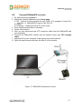
9. Appendix 2. DAEnetIP2 installation
Note these steps are for power on only DAEnetIP2. For installation DAEnetIP2 +
relay board (kit), first you must do the steps from Appendix 3 and then do the steps
from point 9.1 or point 9.2.
9.1.
Connect DAEnetIP2 to computer for first time
1. Connect the DAEnetIP2 device with your computer via UTP crossover cable.
(note that the device does not support AUTO MDIX)
2. Supply with voltage in the allowed range. For example - 12VDC stabilized
filtered power source.
3. Your initial computer IP should be in the device network. So it is recommend
to be 172.16.100.1. Change it.
4. Open web browser and type 172.16.100.2 – default username/password are
“admin”/”admin”
5. Now you can access all the parameters via your web browser
Figure 16. DAEnetIP2 connected directly to computer
-30-
DAEnetIP2 User Manual
18 Nov 2013
9.2.
Connect DAEnetIP2 to router
1. Do all the steps from point 9.1
2. Adjust the network parameters from Setup page:
2.1. IP - must be in same network as your router. (For example if router IP is
192.168.1.1, DAEnetIP2 IP may be 192.168.1.2)
2.2. Mask
2.3. Gateway - usually this is the IP of your router
3. Click submit and wait about 5 seconds
4. Power off the device
5. Now you may disconnect the UTP crossover cable from the DAEnetIP2 and
your computer
6. Connect the DAEnetIP2 module and the network router with UTP straight
cable.
7. Adjust the IP of your computer to be again in the router network
8. Open the web browser and enter the new IP of the module.
Figure 17. DAEnetIP2 connected to router
-31-
DAEnetIP2 User Manual
18 Nov 2013
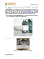
10. Appendix 3. Install and power on DAEnetIP2 + denkovi relay
board (kit)
DAEnetIP2 can be used successfully in combination with relay boards. Bellow are
given instructions how to connect and power on kits (DAEnetIP2 + cable + relay
board). You can view the kits with DAEnetIP2 www.denkovi.com. The steps
(instructions) are valid for only for kits with DAEnetIP2 + cable + relay board from
Denkovi Assembly Electronics LTD without matter how many relays is the kit.
1. Connect DAEnetIP2 UTP crossover cable (if it will be connected to computer) or
UTP stright-through (if it will be connected to router)
Figure 18. Connecting UTP cable to DAEnetIP2
2. Connect the other end of the cable to your computer LAN card or router
Figure 19. Connecting UTP cable to Computer
-32-
DAEnetIP2 User Manual
18 Nov 2013
Figure 20. Connecting UTP cable to router
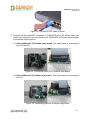
3. Connect the flat cable IDC connector to DAEnetIP2 ports. By default when you
receive the denkovi kit you should have the DAEnetIP2 connected with the cable.
If not please contact with us.
3.1. Internet/Ethernet 16 Channel relay board. The relay board is connected to
ports P3 and P5.
Figure 21. Connecting cable for 16 channel relay board
3.2. Internet/Ethernet 8 Channel relay board. The relay board is connected to
port P5.
Figure 22. Connecting cable for 8 channel relay board
-33-
DAEnetIP2 User Manual
18 Nov 2013
3.3. Internet/Ethernet 2 Channel relay board. The relay board is connected to
P5.7 and P5.8 pins.
Figure 23. Connecting cable for 2 channel relay board
4. Connect each "In" labeled wire into the referred screw terminal of the relay board.
For example "In 1" wire goes into Relay 1 In screw terminal, "In 2" wire goes into
Relay 2 screw terminal and so on.
Figure 24. Connecting "In" wires into the screw terminals
-34-
DAEnetIP2 User Manual
18 Nov 2013
5. Connect the GND wire of the flat ribbon cable into the GND screw terminal of the
relay board. For example bellow it is shown 8 channel relay board. The same is
for the rest relay boards.
Figure 25. Connecting the GND wire to the relay board
6. Connecting power supply
Figure 26. Plug the power supply jack into DAEnetIP2
-35-
DAEnetIP2 User Manual
18 Nov 2013
Figure 27. Connect the +Vcc and GND wires into the relay board power supply
screw terminal as it is shown on the image above.
6.1. Single power supply. You can supply the kit with single power supply source.
In this case it is 12VDC. If you have 24V relay board version, then you must
use 24VDC single power supply source (DAEnetIP2 accept from 7.5V - 25V)
Power source
+12VDC
+
GND
Relay Board
RJ45
Relay
GND
GND From Flat
Ribbon Cable
GND
IP Controler
+12VDC
GND
FLAT
RIBBON
CABLE
+Vcc
IP Controller power
jack
IN
NO C NC
INX
~120VAC
Figure 28. Single power supply source.
-36-
DAEnetIP2 User Manual
18 Nov 2013
6.2. 2 Separate power supplies. You can also supply the kit with 2 separate power
supply sources. If the relay board is 24VDC version, then Power supply
source 2 (for the relay board) is 24VDC. Power supply source 1 (for
DAEnetIP2) may be from 7.5VDC up to 25VDC.
+12VDC
+12VDC
Power supply source 1
Power supply source 2
GND
GND
+
Relay Board
RJ45
Relay
GND
GND From Flat
Ribbon Cable
GND
IP Controler
+12VDC
GND
FLAT
RIBBON
CABLE
+Vcc
IP Controller power
jack
IN
NO C NC
INX
~120VAC
Figure 29. 2 separate power supply sources
To calculate what currency rate power supply you need, you will have to make a
sum with DAEnetIP2 current consumption + relay board current consumption.
DAEnetIP2 current consumption is 50mA at 12VDC. If we have for example 16
channel relay board 12VDC the consumption is 600mA. So you will need power
supply which can provide more than 600+50=650mA at 12VDC. Or 2 supply sources
- one >50mA and another >600mA at 12VDC. You can see the other relay boards
current
consumptions
on
their
referenced
page
http://www.denkovi.com/category/1/relay-boards.html. You just have to find your
model.
7. Now you can power on the devices (for example plug the adaptor into the
electricity network)
8. In case of success you have to see this when you power on the kit
Figure 30. DAEnetIP2 leds. The link led (top) is blinking and the bottom led by
default shows the power on and it is constantly on.
-37-
DAEnetIP2 User Manual
18 Nov 2013
Figure 31. Relay board power led is on constantly.
Figure 32. The kit in working condition. The same is for the other kits.
-38-
DAEnetIP2 User Manual
18 Nov 2013
11.
Appendix 4. Port forwarding - for advanced users
This appendix describes how to access the DAEnetIP2 over the Internet. The
demonstration is done with router "TP-Link TL-WR340G", but it may be done with
any other router supporting "Port Forwarding" function. Bellow are given the steps
you have to go through to make "Port Forwarding".
1. Adjust DAEnetIP2 network ports. These ports are:
• SNMP port, by default 161
• HTTP port, by default 80
DAEnetIP2 will accept any valid integer number for port >1025 and <65535. Port
numbers from 0 to 1024 will be accepted as 161. The same is with port 80.
Let's say we would like to adjust for example:
• Port 10080 for HTTP
• Port 10161 for SNMP
This may easily be done from the DAEnetIP2 web server -> Setup page
2. These ports must be set in the forwarding rules inside the router as it is shown
on the figure bellow
Figure 33. Port forwarding
The IP address 192.168.1.11 is actually the internal address of the DAEnetIP2.
3. Now it is possible to access the DAEnetIP2 from everywhere outside the LAN
(including over the Internet).
xxx.xxx.xxx.xxx:10080 - is the web server of the module
snmpget -v1 -c 000000000000 xxx.xxx.xxx.xxx:10161 .1.3.6.1.4.1.19865.1.1.1.0 snmp command for accessing the module (get the IP)
xxx.xxx.xxx.xxx - the public IP of the router or it's DNS name.
Good online guide for port-forwarding is the bellow link:
http://portforward.com/english/routers/port_forwarding/
-39-
DAEnetIP2 User Manual
18 Nov 2013
12.
Appendix 5. Software
Denkovi Assembly Electronics LTD provides several application that may be
used for testing, demonstrations, configurations and very simple automation projects.
You can see also what else 3rd parity software is available for DAEnetIP2 on this
link http://denkovi.com/page/43/the-3rd-parity-software-for-denkovi-devices-.html
12.1.
DRM Software
Denkovi Relay Manager (DRM) is universal software for easy controlling all kinds
of Denkovi USB, VCP and SNMP and TCP/IP relay boards. It may be used with
DAEnetIP2+relay board.
Figure 34. DRM software
Software web page - here
-40-
DAEnetIP2 User Manual
18 Nov 2013
12.2.
DAEnetIP2 Manager
DAEnetIP2 Manager is configuration utility for Denkovi DAEnetIP2 controller.
Figure 35. DAEnetIP2 Manager
Download link - here
-41-
DAEnetIP2 User Manual
18 Nov 2013
12.3.
Android Software by iSwitch, LLC
The featured Android application is offered to extend control of the DAEnetIP2
controller and relay board to your Android phone. This application is designed to
work on an Android Smartphone or Tablet, however screens are optimized for
Smartphones.
Figure 36. Android application from iSwitch, LLC
Download link - here
-42-
DAEnetIP2 User Manual
18 Nov 2013
12.4.
Control from command line
12.4.1. Windows
Net-snmp is command line tool for accessing SNMP based network devices under
windows console. By default it is not included in Windows OS. DAEnetIP2 can be
easily accessed by the net-snmp tool. This is very useful when the snmp commands
must be executed from batch file for example.
Bellow are the steps for installing net-snmp tool on windows OS.
1. Download the last version net-snmp binary for windows from http://netsnmp.sourceforge.net/download. The file must look like net-snmp-X.X.X.XX.win32.exe
2. Install the downloaded file. Leave the default options. The packet will be install
in c:\usr by default.
3. Download the DAEnetIP2 MIB file from here
4. Copy the mib file here c:\usr\share\snmp\mibs
5. Add new line in the file c:\usr\etc\snmp\snmp.conf with the "mibs all" directive.
6. Now you can test different commands for OID access, supported by this
module. Their names you may see in the DAEnetIP2.mib file.
A simple test may be done to be sure if the tool is installed successfully:
run->cmd->
snmpget -v1 -c 000000000000 172.16.100.2 .1.3.6.1.4.1.19865.1.1.1.0
answer: SNMPv2-SMI::enterprises.19865.1.1.1.0 = IpAddress: 172.16.100.2
For creating batch files, you may use the following steps:
1. Open new file and save it as ON.bat
2. Enter the following code:
snmpset -v1 -c private 172.16.100.2 .1.3.6.1.4.1.19865.1.2.2.1.0 i 0
PING 1.1.1.1 -n 1 -w 5000
snmpset -v1 -c private 172.16.100.2 .1.3.6.1.4.1.19865.1.2.2.1.0 i 1
1. Save the file
2. Run it.
-43-
DAEnetIP2 User Manual
18 Nov 2013
12.4.2. Linux
Usually most of Linux OS come with snmp tool installed.
1. To check out if snmp is installed, just open one terminal and type:
snmpget -v1 -c 000000000000 192.168.1.11 .1.3.6.1.4.1.19865.1.1.1.0
(Of course with your network settings)
If you get some message like this: "snmp is not function" or "snmp not found", it
seems that snmp is not installed and you have to follow the hints that the command
line gives you. After that repeat step 1.
2. Create bash file for example ON.vim and enter the following commands in it:
#!/bin/bash
snmpset -v1 -c private 172.16.100.2 .1.3.6.1.4.1.19865.1.2.2.1.0 i 0
sleep 5s
snmpset -v1 -c private 172.16.100.2 .1.3.6.1.4.1.19865.1.2.2.1.0 i 1
3. Save the file
4. Run it.
12.4.3. Example commands
o SNMPGET examples
Get DAEnetIP2 IP address
snmpget -v1 -c 000000000000 172.16.100.2 Denkovi.DAEnetIP2.Configuration.cfgIP.0
snmpget -v1 -c 000000000000 172.16.100.2 .1.3.6.1.4.1.19865.1.1.1.0
Get the MAC Address
snmpget -v1 -c 000000000000 172.16.100.2 Denkovi.DAEnetIP2.Configuration.cfgMAC.0
snmpget -v1 -c 000000000000 172.16.100.2 .1.3.6.1.4.1.19865.1.1.2.0
Get P6.1 - This will read analog input 1 level. The rsult is from 0 up to 1023.
snmpget -v1 -c 000000000000 172.16.100.2 .1.3.6.1.4.1.19865.1.2.3.1.0
Get P6.8 This will read analog input 8 level. The rsult is from 0 up to 1023.
snmpget -v1 -c 000000000000 172.16.100.2 .1.3.6.1.4.1.19865.1.2.3.8.0
Get the whole P6 (This will return a byte number. Each bit is converted analog input
value. This can be used for digital inputs reading of P6)
snmpget -v1 -c 000000000000 172.16.100.2 .1.3.6.1.4.1.19865.1.2.3.33.0
Get P3.1 - This will read digital output P3.1 level
snmpget -v1 -c 000000000000 172.16.100.2 .1.3.6.1.4.1.19865.1.2.1.1.0
Get P3.8 - This will read digital output P3.8 level
snmpget -v1 -c 000000000000 172.16.100.2 .1.3.6.1.4.1.19865.1.2.1.8.0
-44-
DAEnetIP2 User Manual
18 Nov 2013
Get the whole P3
snmpget -v1 -c 000000000000 172.16.100.2 .1.3.6.1.4.1.19865.1.2.1.33.0
Get P5.1 - This will read digital output P5.1 level
snmpget -v1 -c 000000000000 172.16.100.2 .1.3.6.1.4.1.19865.1.2.2.1.0
Get P5.8 - This will read digital output P5.8 level
snmpget -v1 -c 000000000000 172.16.100.2 .1.3.6.1.4.1.19865.1.2.2.8.0
Get the whole P5
snmpget -v1 -c 000000000000 172.16.100.2 .1.3.6.1.4.1.19865.1.2.2.33.0
o SNMPSET examples
Set DAEnetIP2 IP address
snmpset -v1 -c private 172.16.100.2 Denkovi.DAEnetIP2.Configuration.cfgIP.0 a 172.16.100.3
snmpget -v1 -c private 172.16.100.3 .1.3.6.1.4.1.19865.1.1.1.0 a 172.16.100.3
Set P3.1 - This will set pin 1 from digital output port P3 in '0' (Low level)
snmpset -v1 -c private 172.16.100.2 .1.3.6.1.4.1.19865.1.2.1.1.0 i 0
Set P3.8 - This will set pin 1 from digital output port P3 in '1' (High level)
snmpset -v1 -c private 172.16.100.2 .1.3.6.1.4.1.19865.1.2.1.8.0 i 1
Set the whole P3 - This will set all the 8 pins from digital output port P3 in '1'
snmpset -v1 -c private 172.16.100.2 .1.3.6.1.4.1.19865.1.2.1.33.0 i 255
Set P5.1 - This will set pin 1 from digital output port P5 in '0' (Low level)
snmpset -v1 -c private 172.16.100.2 .1.3.6.1.4.1.19865.1.2.2.1.0 i 0
Set P5.8 - This will set pin 1 from digital output port P5 in '1' (High level)
snmpset -v1 -c private 172.16.100.2 .1.3.6.1.4.1.19865.1.2.2.8.0 i 1
Set the whole P5 - This will set all the 8 pins from digital output port P5 in '1'
snmpset -v1 -c private 172.16.100.2 .1.3.6.1.4.1.19865.1.2.2.33.0 i 255
-45-
DAEnetIP2 User Manual
18 Nov 2013
13.
Appendix 6. Software examples
Software examples can be found on this link
-46-
DAEnetIP2 User Manual
18 Nov 2013
14.
Appendix 7. HTTP API commands
DAEnetIP2 i/o lines can be controlled/accessed via HTTP API commands and
basic access authentication is required to do that. The controller supports only 2
HTTP API commands: for read and write all the i/o lines.
The digital outputs (P3 and P5) can be controlled by sending this HTTP command:
http://admin:[email protected]/iochange.cgi?ref=re-io&01=00&02=FF
admin:admin are the username:password
device.ip.address is the DAEnetIP2 IP address (by default it is 172.16.100.2)
01=00 is the state of P3 DO
02=FFis the state of P5 DO
For example:
http://admin:[email protected]/iochange.cgi?ref=re-io&01=00&02=FF
The i/o states (P3, P5, P6) can be retreived by sending this HTTP command:
http://admin:[email protected]/ioreg.js
it will be received javascript file with several variables and one of them is:
var IO=new Array
(0xFF,0xFF,0x80,0x00AB,0x0049,0x0118,0x014A,0x012F,0x003E,0x0029,0x01DD)
Bytes 0 and 1 are the digital I/O states (in hex format)
Bytes 3...10 are the Analog inputs values (in hex format)
For example:
http://admin:[email protected]/ioreg.js
-47-
DAEnetIP2 User Manual
18 Nov 2013
15.
Appendix 8. Firmware upgrade
Bellow are given the steps for firmware upgrade of the DAEnetIP2 with
DAEnetIP Burner:
1. Download and save the version you need for upgrading the. The binary (.bin)
file must be downloaded from this link
2. Navigate the DAEnetIP Burner application to this file by clicking button with
label “…”.
3. From the Device list select DAEnetIP2.
4. In the IP address field type the IP address of the DAEnetIP2 controller that
must be upgraded. By default it is 172.16.100.2.
5. In the Port field type the target port on that DAEnetIP2 can be reached. This
is the SNMP port. By default it is 161.
6. In the Password field type the SNMP password used in this DAEnetIP2
controller. By default it is "private"
7. Check if the settings are correct by clicking button “Check device”. After
successful connection under this button it must appears text with the
DAEnetIP2 version. If this not happens it means the connection is not
successful and you must repeat again steps 3-7.
8. Set the TFTP Server. This is usually the IP of the user's computer.
9. Set the maximum retries field. This field shows how many times
the DAEnetIP Burner will try to reconnect with the DAEnetIP2 controller if the
connection is lost for a moment. A value of 5-10 is reasonable.
10. Start update by clicking Burn button. If everything is correct, a new line must
appear in the event log and the progress bar must starts moving on.
Figure 37. DAEnetIP Burner
-48-
DAEnetIP2 User Manual
18 Nov 2013
11. Wait until the file is uploaded. This will be indicated when the New
version field is not ??? but some value – form example 1.50. Then the Status
field must be with value “File is uploaded successfully”.
12. Your DAEnetIP2 controller is upgraded successfully with the desired firmware
version. Now when you click button “Check device”, the new version must
appear.
-49-
DAEnetIP2 User Manual
18 Nov 2013
16.
Appendix 9. Digital I/O ports (P3/P5)
This section describes how to use DAEnetIP2 P3/P5 - 8 bit TTL IO port lines.
They are not buffered and you should very carefully otherwise the MCU could
be damaged. They are digital inputs/outputs. The output level voltage is “1”
(3.3VDC) or “0” (0.25VDC) with consumption < 1.5mA. All inputs/outputs have
protection diodes to GND and +3.3VDC.
Below are given sample examples of I/O ports connections to external devices.
The first figure shows how to connect digital output to 12V relay. The second shows
example for 5V TTL signal input. R2 is recommend because sometimes the input
signals are ‘tri-state”.
Figure 38. Connecting relay to digital output
Figure 39. Using digital I/O pin as input
-50-
DAEnetIP2 User Manual
18 Nov 2013
17.
Appendix 10. Using analog inputs port (P6)
Each Analog input from port (P6) have two protection internal diodes shown on
figure 40. However they are useless if the resistor R1 is not connected in the way
shown on the figure. In order to protect each analog input and the whole DAEnetIP2
it is strongly recommend to connect R1 resistor (with value 22K for example) to
each analog input (P6.x). Using analog input without such resistor may cause easy
overvoltage or reverse voltage and damage of the controller.
Figure 40. Using analog inputs port P6
-51-
DAEnetIP2 User Manual
18 Nov 2013
18.
Appendix 11. Using analog temperature sensors
18.1.
LM335Z
Figure 41. DAEnetIP2 and LM335Z
On the figure above it is shown LM335Z connection to DAEnetIP2 with several
resistors. LM335 may be assumed as zener diode it is necessary to limit the
current (that's why the 4.7K resistor is added). The biggest disadvantage of
LM335 is the high output voltage during 25°С – 3V. As DAEnetIP2 ADC works
in range of 0-3.3V, actually with directly connected LM335 it is not possible to
measure temperatures over 57°С. Moreover the output of LM335Z can exceed
3.3V and damage the ADC channel.
The easiest solution is using simple resistor divisor – 3:1 so the output voltage
during 25°С to be 1V. It is important the divisor resistance to be smaller because this
improves the ADC accuracy (but on the other hand it must be taken in mind also the
current in the sensor resistor). However the resistor divisor makes also the ADC
conversion bigger.
-52-
DAEnetIP2 User Manual
18 Nov 2013
18.2.
LM35DZ
Figure 42. DAEnetIP2 and LM35DZ/LM34DZ
When using LM35DZ all the disadvantages of LM335 are avoided – there is no need
of current resistor (as this sensor does not work as zener diode) neither output
divisor. Also its initial error is better than LM335. The only disadvantage is the
minimal voltage is 4VDC and this makes the connection to DAEnetIP2 more difficult
(it can not be connected directly with only single IDC connector to P6). The 27K
resistor acts like protection of the analog input P6.X and it is strongly recommend.
-53-
DAEnetIP2 User Manual
18 Nov 2013
18.3.
MCP9700A
Figure 43. DAEnetIP2 and MCP9700A
This sensor – MCP9700A works in range 2.3 – 5.5V and that allows to be supplied
from 3.3V pin which is mapped to P6 jumper. Generally its parameters are bett er
than the LM335Z and LM35DZ.
-54-
DAEnetIP2 User Manual
18 Nov 2013
19.
Appendix 12. Mechanical drawing
Figure 44. Mechanical drawing
-55-
DAEnetIP2 User Manual
18 Nov 2013
20.
Document revisions
• 22.03.2012 - First official document version (for firmware version 4.084)
• 11.02.2013 - Update with the new features of DAEnetIP2 regarding
firmware version 4.097
• 08.04.2013 - Wiring diagram for LM335Z- correction
• 12.09.2013 - Added appendix: Using analog inputs (P6)
• 18.11.2013 - Port P3 and P5 control all pins via SNMP, correction of the
OIDs.
-56-